1
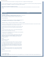
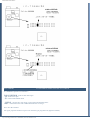
KB2LJJ Radio Mods Database
KB2LJJ
Home
Radio Mods Database and Manuals
Modifications for the Icom IC-706MKII
ICOM 706 MKII Extended transmit mod
Special on IC706mkII
TX range expansion for IC-706MKIIG
www.r6-ru4montesecchieta.it
Expand only mod for the IC-706MkII
Mike Amp Mod for IC 706 MK II
IZ5CCV
mods IC706 MKIIG por EA1DOU (ver. Española)
Modifikation IC-706MKIIG für 9k6 PR und Pactor
IC-706MKIIG mod
More talk power on SSB from your Icom 706Mk2/Mk2G and Alinco
DX70TH
Mods for Japanese version IC-706MK2G
Icom IC-706MK2 cw keyer
IC-706MK2G increase recieve
Icom 706mkIIG Mic
Convert IC-706MK2G from American to European version
ICOM 706 Mk2G IF filter change
IC-706mkIIG fan mod
ICOM LDG interface and ICOM IC-706MKIIG
ICOM 706 MKII Extended transmit mod
From: "Len SantaMaria, KC2ADV"
This file may be freely distributed as long as it remains intact, with no modifications, additions, or deletions.
DISCLAIMER:
I assume no responsibility for damage or inaccuracies contained in this document. In other words, USE THIS AT YOUR OWN
RISK. It worked for me, however I don't know if it will work for you.
WARNING #1: This mod requires the ability to remove surface mount diodes. Only those who are qualified to do this should
attempt this mod.
WARNING #2: This mod seems to erase all memory channels, etc. You may want to save this info for reprogramming.
Disassembly:
1. Face the front of the radio towards you.
2. Remove the three screws in a row across the middle of the top of the radio.
http://www.kb2ljj.com/data/icom/ic-706-MKII.htm (1 di 30)23/08/2009 23.05.07
KB2LJJ Radio Mods Database
3. Remove the two screws at the top rear (on the sides) of the radio.
4. Pry the top cover off from the back.
5. Disconnect the speaker at the connector.
Modification:
6. Near the top rear of the main circuit board, there is an small, oblong metal can. Directly below the right side of this can is
two surface mount diodes with a white silk-screened box around them. There is also what appears to be a circuit board part
number just to the left of it (mine says B4916D). Remove the LEFT diode in the box.
7. To the left of this, there is a test point marked CP3. Just to the left and above this test point is another box with two
*vertically* mounted surface-mount diodes (Note: there is also a place for 5 more *horizontally* mounted diodes, with 3
installed). Remove the LEFT vertically oriented diode.
Reassembly:
8. Reconnect the speaker.
9. Put the top cover back on. Insert the top cover tabs into the slots and lower into position.
10. Replace all of the screws.
My radio did not require a reset, however I did lose all of my channel memories. It seems to be able to transmit everywhere except
below .5 Mhz. I have not tested the power output at all frequencies yet.
I hope this helps everyone who have been waiting patiently for this mod.
Any comments can be directed to me:
Len - KC2ADV
email: [email protected].
From: "Rafel" [email protected]
If you can read this, its come from Your www:
Len - KC2ADV
email: [email protected]
... wrote:
...
>Modification:
>6. Near the top rear of the main circuit board, there is an small, oblong
>metal can. Directly below the right side of this can is two surface mount
>diodes with a white silk-screened box around them. There is also what
>appears to be a circuit board part number just to the left of it (mine
>says B4916D). Remove the LEFT diode in the box.
>7. To the left of this, there is a test point marked CP3. Just to the left
>and above this test point is another box with two *vertically* mounted
>surface-mount diodes (Note: there is also a place for 5 more *horizontally*
>mounted diodes, with 3 installed). Remove the LEFT vertically oriented
>diode.
For first, my circuit board part number is B4916F, i don`t understand you what diodes i must cut off, explain me, my smd diodes
looks like this:
O<>O
O
O<>O
O<>O 4
O<>O
J25
O
O
http://www.kb2ljj.com/data/icom/ic-706-MKII.htm (2 di 30)23/08/2009 23.05.07
7
O 6
5
3
O
O
KB2LJJ Radio Mods Database
1[]
O
[] 2
B4916F
O
8[]
[]9
O
O
CP3
<__]
Diodes: 1,2,3,4,5,7,8,9 are instaled
Diode: 6 is not instaled
My version is with Tone 1750Hz, European i think, RX 30kHz-200MHz, TX in amateur bands only, the serial number if needed
is: 02101 buyed in 18.06.97 as new in Poland.
Sorry for my bugs.
Can You type me what diodes ? I think 1 and 3.
Rafa´ SP6-1313WR, Klub SP6KBE :) Kontakt: [email protected]
Info on the diodes from another European user:
d129
---- (d111 none)
d112
d113
d114
d
1
1
6
d
1
1
5
d
1
1
8
d
1
1
9
D116 and D118 are responsible for out of band TX. D115 and D119 enables RX from 30KHz to 200MHz. D113 is responsible for
6M RX and D114 is responsible for 6M TX. I do not have info about D129 and D112.
Rafa3 SP6-1313WR, Klub SP6KBE :) Kontakt: [email protected]
http://www.kb2ljj.com/data/icom/ic-706-MKII.htm (3 di 30)23/08/2009 23.05.07
KB2LJJ Radio Mods Database
Special on IC706mkII
From: SM6WXO
I have tried some special buttons on IC706mkII:
Push TS and DISPLAY while power up and you will see a strange power on check.
Push P.AMP/ATT and RIT/SUB while power up and you will be able to see SHIFT-ADJ on your 706mkII. Dont know what this
is for, recalibrating ?
I think that these things even works on the older version of 706, dont know.
73 - Dennis, SM6WXO @ SM6JZZ
TX range expansion for IC-706MKIIG
Author: Karel OK1DNH - [email protected]
TX range expansion on HF, VHF and UHF is very simple. When modified the radio will also transmit AM mode in the aircraft
band with approximately 1 watt at 118 MHz to about 17 watts am carrier at 136 MHz.
On MAIN BOARD under speaker near Xtal you can see two rows of solder dots for SMD components. Only on position 10 (from
left) is diode (D2030), which is necessary to remove.
Thats all.
After connecting power radio will be reseted and TX range is expanded.
http://www.kb2ljj.com/data/icom/ic-706-MKII.htm (4 di 30)23/08/2009 23.05.07
KB2LJJ Radio Mods Database
More pictures from Ken Bessler KG0WX.
http://www.kb2ljj.com/data/icom/ic-706-MKII.htm (5 di 30)23/08/2009 23.05.07
KB2LJJ Radio Mods Database
Transmit power output after modification
Power output in watts as measured from an uncalibrated Diawa CN-620 wattmeter with vhf,uhf dummy load. Power output on
radio set to highest level.
FREQ
FM PWR AM CARR FREQ
FM PWR
105 MHz 1.0
0.0
400 MHz 2.0
110
1.0
0.0
405
7.0
115
2.0
0.0
410
9.0
118
3.5
0.7
415
10.0
120
5.0
1.0
420
12.0
125
14.0
3.5
425
15.0
130
20.0
15.0
430
18.0
135
25.0
17.0
435
20.0
140
28.0
18.0
440
20.0
145
32.0
18.0
445
19.0
150
32.0
18.0
450
18.0
155
20.0
18.0
455
15.0
160
13.0
10.0
460
8.0
165
6.0
1.5
465
0.8
170
1.5
0.0
467
0.15
175
0.5
470
0.00
180
0.1
185
0.0
These are the readings I took after performing the mod. I took readings at key frequencies throughout the band to measure the
efficiencies of the different band pass filters, especially in the HF band. The attenuation at the edges of the filters are very visible
especially at the 8MHz cross point.
All readings were took with a bird wattmeter and a home made RF voltmeter, the latter is not reliable over 200MHz.
Thanks. Olivier, VE2NSM.
MHz
V @ 50 Ohms
0.1
0.2
0.3
0.5
0.65
0.75
0,00
0,04
0,31
1,95
4,16
8,60
W from Bird
Wattmeter
1,5
http://www.kb2ljj.com/data/icom/ic-706-MKII.htm (6 di 30)23/08/2009 23.05.07
W from RF Voltmeter
0,00
0,00
0,00
0,01
0,11
0,59
KB2LJJ Radio Mods Database
0.85
0.95
1.2
1.5
1.995
2
3
3.995
4
6
7.995
8
10
14.995
15
20
21.995
22
25
28
29.995
30
35
38
40
43
48
50
54
56
58
59.5
59.995
60
62
65
70
75
78
80
83
86
90
95
100
105
110
115
120
125
130
135
140
24,20
52,00
98,20
99,40
104,70
107,90
101,40
104,60
95,80
103,40
88,60
99,70
103,20
101,90
102,40
102,40
101,80
102,20
101,20
99,50
97,90
95,60
93,80
91,30
89,30
95,10
97,30
98,00
100,20
100,90
99,10
94,10
89,90
13,50
16,50
26,40
55,40
63,30
71,00
71,90
65,50
54,40
39,20
22,00
14,30
12,10
9,80
7,40
7,30
11,30
22,60
47,00
63,20
7
18
75
80
87
86
92
95
92
96
75
95
98
96
96
96
95
96
94/92
90/90
86/87
82/82
80
76
77
85
89
90
93
94
90
82
72
1
1,25
3
14/22
22/37
27/50
2752
22/40
15/28
7/14
1,5/4
0,75/1,8
1,3
1
0,5
1
5,2
21
37
http://www.kb2ljj.com/data/icom/ic-706-MKII.htm (7 di 30)23/08/2009 23.05.07
5,25
25,01
90,37
92,61
102,82
109,25
96,40
102,62
85,98
100,27
73,45
93,17
99,88
97,36
98,32
98,32
97,17
97,94
96,02
92,80
89,81
85,61
82,40
78,03
74,62
84,71
88,71
90,00
94,12
95,45
92,05
82,93
75,64
1,56
2,37
6,27
28,44
37,25
46,98
48,19
39,91
27,41
14,09
4,31
1,76
1,23
0,79
0,43
0,41
1,07
4,56
20,37
37,13
KB2LJJ Radio Mods Database
145
150
155
160
163
165
167
169
171
174
178
183
190
195
199.995
400
405
410
415
420
425
430
435
440
445
450
455
460
463
466
468
470
70,30
48
72,20
52
60,00
34
39,50
15,5
29,90
9
22,10
5
15,50
2,5
10,60
1,2
7,40
0,5
4,40
1,91
0,33
0,16
0,35
0,60
6,33
0,8
14,10
3,8
18,30
6
20,70
7,5
24,10
10
31,10
17
30,20
16
29,20
15
30,90
16
30,30
16
28,00
14
27,40
13
20,60
8.5
14,50
4.5
7,80
1.6
4,50
0.6
2,35
2-30MHz plug
2-30Mhz plug / 25-60MHz plug
25-60MHz plug
25-60MHz plug / 100-250MHz plug
100-250MHz plug
200-500MHz plug
Not reliable
46,05
48,59
33,42
14,31
8,10
4,35
2,08
0,93
0,43
0,13
0,01
0,00
0,00
0,00
0,00
0,30
1,70
2,94
3,80
5,20
8,78
8,27
7,72
8,67
8,32
7,08
6,77
3,76
1,81
0,48
0,14
0,03
Expand only mod for the IC-706MkII
It should be well know, that the IC-706mkIIG does not offer the best frequency stability. You might have already recognized this
if you ever used your 706 for modes like JT65. For these modes is it very important to have a very low frequency drift.
Unfortunately, the TCXO (CR-282) doesn't really help in this case. It does improve the stability but not really the drift during the
first minute which is the most important one in WSJT since the TX-time is less than a minute. This modification consists two
things, replacing a varicap-diode by a capacitor and give the fan some power so he runs even in receive mode. Once this
modification is done, the frequency stability is improved a lot as seen in picture 1.
http://www.kb2ljj.com/data/icom/ic-706-MKII.htm (8 di 30)23/08/2009 23.05.07
KB2LJJ Radio Mods Database
Picture 1: frequency drift vs. temperature
Just a few steps to improve the frequency stability of your IC-706mkIIG:
1. Remove the lid on the back, then remove the little lid of the XO (as shown in picture 2).
Picture 2: open the lid of the XO
2. Locate the little varicap-diode right next to the L601 (picture 3). Remove this diode.
http://www.kb2ljj.com/data/icom/ic-706-MKII.htm (9 di 30)23/08/2009 23.05.07
KB2LJJ Radio Mods Database
Picture 3: diode is right next to the L601
3. Now replace this diode by a 33pF ceramic capacity (N470). The one leg to the upper solder pad where the diode was, the
other to ground. Ground can be easily found at the metal shielding.
4. As you know, the radio gets very hot just by receiving because the fan does not work if you do not transmit. The fan
should run all the time. This can be done by simply inserting a 100Ohm resistor (or two 56Ohm, ¼ Watt in serie) between
the red fan wire and the top of the inductivity as shown in picture 4. The fan runs now very slowly all the time.
5. You may now let the radio run for about 20minutes. Tune to 50MHz and check the frequency by transmitting. If the
frequency does not match, adjust it by tuning carefully with L601.
This modification has been done on several radios. It always worked very good but I cannot give a guarantee. I am not
responsible for any damages on your radio.
http://www.kb2ljj.com/data/icom/ic-706-MKII.htm (10 di 30)23/08/2009 23.05.07
KB2LJJ Radio Mods Database
Expand only mod for the IC-706MkII
Author: David Spicer,VK7ZDJ
HI ALL, as an owner of a IC-706MkII, I have noticed that there is no detailed photos of how to go about the mods on any of the
mod sites, so I pulled my radio out of the car and I have taken some photos of the only mod that I was interested in doing to my
radio,............EXPAND RX /TX.
I hope that the photos will help all new owners and or old ones that have not been game enough to tackle the mod, its quite a
simple mod to do as long as you have good quality desoldering equipment, if not then do not attempt it, take it to someone that has
the gear.
If you follow the text file on this page by "Len SantaMaria, KC2ADV"
headed,.......Icom 706 MkII Extended Transmit Mod and use my photos as a reference then I do not think you can go wrong, my
radio works like magic.
PLEASE NOTE THAT THESE MODS WERE DONE TO AN AUSTRALIAN IC-706MkII RADIO,........AS FAR AS I CAN
TELL THERE IS NO DIFFERENCE BETWEEN MY RADIO AND THE AMERICAN MODEL, IF ANYONE FINDS THIS
NOT TO BE CORRECT THEN I AM SORRY BECAUSE I CANNOT HELP YOU.
http://www.kb2ljj.com/data/icom/ic-706-MKII.htm (11 di 30)23/08/2009 23.05.07
KB2LJJ Radio Mods Database
http://www.kb2ljj.com/data/icom/ic-706-MKII.htm (12 di 30)23/08/2009 23.05.07
KB2LJJ Radio Mods Database
This information and photos was supplied by David Spicer,VK7ZDJ.
User comment
Expanded tx mod works on Canadian Model
From: ve7it
I removed the 2 diodes listed in the mod and it works beautifully. As well as clearing memories, the mod will clear information
related to the installed optional filters. You will need to go into the intial setup menu and reselect any optional filters you have
installed. See page 49 of user manual, Menu items 19 and 20. While you are in there, check the other settings. To enter the intial
setup menu, you hold down the lock button and power on the radio.
Mike Amp Mod for IC 706 MK II
It is based on information provided by ICOM Europe.
The level of the IC 706 MK II microfone amplification does not satisfy under certain circumstances like heavy pile up or operators
with faint voice.
A litle modification does help to increase the amplification level a lot: The 5,6 k ohm SMD type resistor R235 located on the main
unit has to be replaced by an approximately 1,0 k ohm type.
After modification the personal level of the microfone amplifier can be set in the initial setup (menue Q2).
1. To replace the resistor first open the top of the case by unsrewing the 3 screws in the middle and the 2 screws back on the
left and right side. Remove the top carefully and disconnect the loudspeaker cable.
2. Locate the main unit ( the one near the display front side) and disconnect all connectors.
3. Locate the 5 screws holding the main unit and unscrew them.
4. Pull out the main unit and turn it over. This is the side of interest.
http://www.kb2ljj.com/data/icom/ic-706-MKII.htm (13 di 30)23/08/2009 23.05.07
KB2LJJ Radio Mods Database
5. Locate the SMD resistor R325 and unsolder it. Solder in the approximately 1.0 k ohm type.
6. Reassemble the main unit.
7. A reset of the radio is not necessary.
8. Don`t forget to set your personal mic amp level in the initial setup (menue Q2).
Remarks:
Although I modified my own IC 706 MK II without any problems I certainly will not be responsible for any damage of your radio
following this modification description. You are acting on your own risk.
http://www.kb2ljj.com/data/icom/ic-706-MKII.htm (14 di 30)23/08/2009 23.05.07
KB2LJJ Radio Mods Database
vy 73
Juergen, DL5EBS
mods IC706 MKIIG por EA1DOU (ver. Española)
http://www.kb2ljj.com/data/icom/ic-706-MKII.htm (15 di 30)23/08/2009 23.05.07
KB2LJJ Radio Mods Database
Modifikation IC-706MKIIG für 9k6 PR und Pactor
Author: André Loos DO1CAL
Es folgen 4 Bilder im *.gif - Format die den Umbau für 9k6 PR und Pactor beschreiben für den IC-706MKIIG.
Viel Spaß damit. Ich übernehme keine Haftung für evtl. entstehende Schäden am Transceiver !
Die 4 Dateien habe ich im PR-Netz gefunden.
IC-706MKIIG mod
Author: Tobias, DL1TWA
Okay, I've got a new Icom IC-706MKIIG info for you:
There is a mod saying:
"Push P.AMP/ATT and RIT/SUB while power up and you will be able to see SHIFT-ADJ on your 706mkII. Dont know what this
is for, recalibrating ?"
I have tested this and figured out the following:
When the SHIFT knob is in the middle position and you press SHIFT-ADJ, then "Good" is displayed. Nothing happens after
power on.
But when you turn the SHIFT knob a little to the left or to the right, then good is displayed and next time you power up you have a
modified shift adjustment. The SHIFT graph is different, too!
http://www.kb2ljj.com/data/icom/ic-706-MKII.htm (16 di 30)23/08/2009 23.05.07
KB2LJJ Radio Mods Database
If you turn the knob a bit more to the left or to the right, then "Error" is displayed and nothing happens.
I wrote to Icom Europe and they say, that this function (P.AMP/ATT + RIT/SUB) is only used in the factory during the production
process of the IC-706MKIIG. to calibrate the centersetting of the shift know.
Afterwards a new calibration shouldn't be necessary.
When you press the arrow in the SHIFT-ADJ menu for one second, the position of the shift know is stored as the new center
setting.
User comment
706 mod
MODIFICATIONS:
WARNING: Improperly performed modifications can severely damage your
radio. have performed these modifications successfully, but I
offer no guarantee or warranty for them. Proceed at your own risk.
TOOLS NEEDED:
1) Small philips-head screwdriver 2) Tweezers 3) Magnifying glass 4)
Low-wattage (15 watt) soldering iron 5) Long-nosed pliers
MODIFICATION 1: Enables out-of-band transmit for 1.6 MHz to 54 MHz.
This does not enable extended VHF transmit This does not enable AM or FM broadcast band transmit. Your memories will be
cleared after this modification, since you need to reset the CPU.
1) Open the top of the radio by removing the 3 top screws and 2 side
screws. Look at the radio from the with the front panel facing you.
screws.
2) Gently pull up the speaker and set is aside without damaging the
speaker or the wires that attach it to the rig.
3) Note the silver rectangular box near the middle of the PCB marked
something like "9 MHz SSB Filter".
4) Move your eyes up from this filter toward the back of the radio.
Just before you get to the "D 108" marking, you will see two tiny
diodes, two blank spaces, and one additional diode. They look
something like this:
D108
[XX] [XX] [ ] [ ] [XX]
Remove this diode ^^^^
5) The second diode from the left needs to be removed. I did this
by crushing it with long-nosed pliers. You can also heat it with a
low-wattage soldering iron and pull it up with tweezers. Be sure
not to damage the other diodes or the PCB. Be sure that you don't
apply too much heat, since the heat can damage the PCB and the
other diodes.
6) Re-assemble the radio. Reset the CPU by pressing and holding
down the UP and DOWN buttons on the front panel and pressing
POWER.
Improved VHF recieve mod:
154-200 MHz RANGE
To open up the 154-200 range,cut the yellow wire on the plug labled "j-4" on the right side of the radio on the bottom,the book
points to this connector.
http://www.kb2ljj.com/data/icom/ic-706-MKII.htm (17 di 30)23/08/2009 23.05.07
KB2LJJ Radio Mods Database
did this and it opened up the rx between 154-200 mhz.
(It was printed in CQ VHF a couple of months ago.)
For those who like to scan VHF Hi-band, there is a mod that restores sensitivity, but at the cost of reduced sensitivity below 120
MHz.
This allows the filter to switch at the corner frequency (apparently around 129 MHz) as you tune.
PROCEED AT YOUR OWN RISK
There are no guarantees you won't trash your radio.
Remove the radio top and bottom covers according to the manual.Remove the speaker. Now with the radio facing you and right
side up, you'll see a single connector with discrete wires at the rear of the control board. The fourth wire from your left should be
a yellow wire
(caution, the 5th and 6th wires on the other end of the connector are yellow too, don't get confused).
Disconnect this wire from the connector. This will enable the 2 meter band-pass filter to work outside the 2 meter band, and will
restore sensitivity between about 130 MHz and about 165 MHz (above and below that range, sensitivity still stinks, especially
above 165 MHz).
Before this mod, a low pass filter with a corner frequency around 129 MHz was in the circuit all the time except when you were
actually tuning inside the 2 meter band, and that killed high band sensitivity completely. Before removing the yellow wire,
sensitivity at 155 MHz was 30 uV for an S1 indication,after the yellow wire is removed, sensitivity increases so that only 0.5 uV
is required for a S1 reading. At 165 MHz after the mod,sensitivity is 3 uV for an S1 reading, before the mod, a very large signal
was required for an indication.
Disconnecting the yellow wire has the unfortunate side effect of reducing sensitivity between 60 and 129 MHz since the radio
never switches from the 2m bandpass filter to the low pass filter. Signals below 60 MHz don't go through either filter and are
unaffected by the mod.
Now here's how to get the low pass filter back when tuning below 129 MHz. On the bottom board, right behind the MENU
button,
there are 5 SMD transistors. These transistors apparently switch the VCOs for the various band segments. The one in the middle
of the 5 apparently switches the 60-129 MHz VCO. The single pin (one side of the SMD transistor has 2 pins the other only 1)
switches to 5 volts when this VCO is active, and is low otherwise.
This is exactly what we need to feed the yellow wire. There's a board trace coming from this pin over to a feedthru hole near J8.
Connect the yellow wire you disconnected earlier here.
The filter should now toggle between low pass and 2m bandpass as you tune below and above 129 MHz, and you should have
good sensitivity both above and below this frequency (at least up through 165 MHz).
Remember, CAUTION WARNING This is tiny SMD stuff. If you trash your radio, you're on your own.
As far as FM Broadcast intermod in the Aircraft band, I noticed the IF is a little overdriven into compression, so I turn the
preamp off(greeen to no light---preamp switch), and noticed no difference in sensitivity, intermod in aircraft band disappeared.
Running the preamp in the Aircraft 118-129 does not really help sensitivity, even though the S-meter shows higher signal levels
(jumps around alot due to saturating IF when signals are not there!!! )
the noise floor actually, degrades, thus I leave the switch (no preamp-black instead of green). Leaving it on green is just driving
the IF into saturation, with worst dynamic range.
Now connecting it to the VCO switch bank, the radio performs to my satifaction, hearing the weather at 162, forestry at 171, TV
audio
near 200Mhz and remembering to turn the preamp off in 118-129 aircraft region, no 2 meter images any more in 82-83Mhz area
from 2 meters.
I can listen to FM broadcast in the 88-108Mhz area.
Q: Does this mod affect HF or 6m?
A: The mod affects only frequencies above 60 MHz. If you just cut or
remove the yellow wire, the 2m bandpass filter is used all the
time.
http://www.kb2ljj.com/data/icom/ic-706-MKII.htm (18 di 30)23/08/2009 23.05.07
KB2LJJ Radio Mods Database
After the mod you can listen to the airport on 134 MHz but 128.4 is still drowned in intermod from the FM BC band.
Proceed at your own risk
The receiver sensitivity above 120MHz (except the band between 144-148MHz) is very poor and also the transmitted FM
deviation for NARROW FM is too small; therefore I did some tests and came to the following two modifications.
To carry out these modifications it is necessary to use the IC706 service manual, which can be bought at any ICOM dealer.
1. When choosing NARROW at FM, then during transmitting the max.
deviation is reduced from 4.8kHz to 2.4kHz. It is still desirable
to choose NARROW at FM because the receive performance is better
then.
After changing resistor R272 from 1K to 8K2. (at the bottom side of the MAIN UNIT), then the max. deviation during
transmitting goes from 4.8kHz to 4.3kHz when choosing NARROW at FM.
The modulation at AM is also changed now, but this can be corrected with potmeter R271.
2. To improve the receiver sensitivity between 120 - 144MHz and
between 148 - 200MHz the following modifications can be carried
out.
At the PA UNIT, change the 60 - 200MHz bandpass:
1) Remove C53(20p), C152(20p), C153(12p) and C154(20p).
2) Short-circuit L49(82nH) by soldering an interconnection at the
place of the removed C153.
3) The inductance of L16, L17, L18 and L19 must be reduced somewhat.
This can be done by separating the windings somewhat with a small
screwdriver.
Now the sensitivity is good up to about 175MHz. Also the sensitivity in the airband is much better now.
For receiving above 175MHz the low-pass filters at the ANT2 input have to be changed (components around L16, L17, L18,
L19.
I would not recommend that, because the spurious suppression during 2M transmitting becomes worse then!
To expand the band on the VHF portion.
(I have not tried this mod.
I received this infomation via e-mail)
Caution: This is quite involved. If you are not too good you might be advised to get someone who has the experience to handle
this mod!
1. Remove the main board from the unit.
Keep the cutout hole away from you. This I consider the top of
the board.
2. Remove the shield from the top of the board. There are 30-40 solder
points from the shield to the board.
3. Under the board on the top of the board, remove R-353 and Q-38.
They are located to the left of the IC-36 chip on the top of the
board under the shield.
4. On the underside of the board, Locate IC-32. There are two IC
chips.
IC-32 will be just down and to the right of the shield.
5. Using a pointer, point at the left upper pin, and go toward the
top of the board. You will find a trace that stops. It comes out
http://www.kb2ljj.com/data/icom/ic-706-MKII.htm (19 di 30)23/08/2009 23.05.07
KB2LJJ Radio Mods Database
from under IC-31, and stops. It should be the sixth trace up from
the top of the Chip.
6. Using a Xacto knife, (or something similar) Cut the trace the bend
halfway between IC-31 and the solder point.
7. Make a jumper wire, and jump the connection, from Pin 11 of IC-32
to the newly isolated trace.
8. Reassemble the radio.
Transmit from 200 Hz to 200 MHZ continuous!!!
ICOM does not warranty these mods.
More talk power on SSB from your Icom 706Mk2/Mk2G and Alinco DX70TH
The following adjustments are to increase the average talk power on SSB for the above radios. If your radio is still under warranty,
check with your supplier to ensure warranty will not be invalidated
For both these adjustments you will need a very small cross-point screwdriver and a steady hand! Do not proceed if you are not
confident!
Alinco DX70TH: Turn up the microphone gain as detailed in the manual. This should be set to maximum. The adjustments
described here is concerned with the ALC control. ALC action is indicated by the TX light which should glow brighter when
speaking into the microphone.
http://www.kb2ljj.com/data/icom/ic-706-MKII.htm (20 di 30)23/08/2009 23.05.07
KB2LJJ Radio Mods Database
Remove the top cover and locate the high power/50w switch (this switch location is detailed in the manual, it is the only switch
visible under the top cover). To the left of the switch there should be a small pot which is for the ALC. Just above the pot printed
on the circuit board is 100w. Set the radio to 28Mhz and while speaking into the mike turn the pot counter clockwise until the TX
light just fails to glow brighter. Back off slightly to restore the increase in brigthness of the TX light while speaking into the
microphone. Replace the top cover.
This adjustment increases talk power considerably and for local contacts on SSB the compressor should be switched off.
Icom 706Mk2/Mk2G: The Icom 706 series are notorious for low talk power on SSB. A simple tweek of the ALC can solve the
problem. This procedure was published in Radcom July 1999 but is updated here to include the IC706Mk2G. As far as I can
ascertain, the later model 706MK2G seems not to suffer from the problem of low talk power and this mod may not be necessary.
Remove the top cover. At the front edge of the main circuit board (to the left of the crystal filter slots, with the front of the radio
facing you) should be a small pot. In the 706Mk2 this is R511 and in the 706Mk2G it is R579 (the number is not actually printed
on the board!). The pot may be obscured by printed ribbon. This pot needs to be turned clockwise while speaking into the
microphone, with power set to high and microphone gain at 6 (compressor should be switched off). Adjust for maximum talk
power.
The article in Radcom claims that this adjustment will bring the 706Mk2 up to 100w pep without the need for the compressor. For
the 706MK2G (early models), adjusting R579 can give a dramatic increase in talk power although you will find that you will still
need to have the microphone gain turned up to 10 and the compressor switched on. On my own set I have noticed that some bands
give more talk power than others. On 160, 80 and 2 meters I get nearly full power by speaking into the mike (gain at max and
compression on). However on other bands the increased talk power is not so dramatic particulalry on 10, 20 meters).
Another way to boost the talk power on the 706 series is to use a preamplified microphone. If you do decide on a preamplified
microphone reset R511/R579 back to it's original postion or distortion may result.
This article can also be found at http://www.qsl.net/g0fvi/adjust.html.
Mods for Japanese version IC-706MK2G
Hello. I found this picture on a Japanese website about how to mod the Japanese version of the IC-706MK2G. I recently bought a
Japanese version of this radio. It seems that the Japanese version is a bit different when it comes to the diode configuration.
I did first remove the D2030 diode on my radio, but that did not open up the TX range. Then I removed the D2028 diode, and this
opened up TX from 1,6-26 MHz and 28-30 MHz.
TX is still only 50-54 + 144-146 + 430-440 MHz on VHF/UHF. RX is now 0,030-200 MHz + 400-470 MHz. For my purposes it
works fine with this range.
Later I found this picture on a Japanese site suggesting that only D2028 is to be removed on the Japanese version. I don't
understand the Japanese text, so maybe someone can translate it ?
http://www.kb2ljj.com/data/icom/ic-706-MKII.htm (21 di 30)23/08/2009 23.05.07
KB2LJJ Radio Mods Database
User comment
ICOM706MK2G MODS JAPANES TEXT TRANS
IC-706MK2G Japanese text translate !
改造後 受信周波數 : mods is after RX ranges
~ 側 : front cover open
~取 : removed the D2028 diode
~送信改造 : mods is after TX ranges. removed the D2028 diode front.
CB帶~ : citizen band also and V/UHF Band Mods is TX range...
have nice TRX mods!!!
All rig for japanese market not open on cb channel (cpu programed for japanese market)
http://www.kb2ljj.com/data/icom/ic-706-MKII.htm (22 di 30)23/08/2009 23.05.07
KB2LJJ Radio Mods Database
Icom IC-706MK2 cw keyer
Author: colin f5vhz - [email protected].
This mod is for the mic of a IC-706MK2. This allows better use of cw by installing a paddle in the mic.
Wire the contacts of a dissassembled relay with an isolated paddle (important) to the up down contacts and remove the old buttons
from the small board and glue them in to the top of the mic to fill the holes
enjoy colin f5vhz
http://www.kb2ljj.com/data/icom/ic-706-MKII.htm (23 di 30)23/08/2009 23.05.07
KB2LJJ Radio Mods Database
IC-706MK2G increase recieve
If you would like to increased receive on your 706mk2g, here is the procedure.
Take off top cover with front facing you. Behind the left of the VFO against the front of the case is 2 square cans with black
Phillips screws in them. Don't adjust these, right behind them in the middle is a metal adjustment screw that looks like most of
the other ones, like the adjustments for power etc.
Have your radio on SSB and turn clockwise and you will hear the receive increase. Only turn it a little, that does a lot, you don't
want to over do it. Too much will bring in a lot of noise.
I've done it to mine and it really made the ears better than from the factory. As you know, the receive is great on these rigs, but this
improves it more. It takes a jewelers flat head screwdriver, be careful. I'm not responsable if you mess up.
73s
Icom 706mkIIG Mic
Author: Tom
This information will allow the use of an Icom HM-56A DTMF mic with an Icom 706. I have ONLY used this on my 706mkIIG
so test it on all others at your own risk.
You will need an 8 conductor (RJ-45) ethernet connector (male) and a crimping tool. Radio shack has a non-crimp version if you
don't want to invest $45 for a new tool.
If you place the tab down, pin 1 is the furthest to the left (see picture)
http://www.kb2ljj.com/data/icom/ic-706-MKII.htm (24 di 30)23/08/2009 23.05.07
KB2LJJ Radio Mods Database
The color code is:
1. Red
2. Black
3.
4. Green
5. Braid
6.
7. Blue
8.
User comment
http://www.kb2ljj.com/data/icom/ic-706-MKII.htm (25 di 30)23/08/2009 23.05.07
Mic input ?
From: Guy ZL2VBV
KB2LJJ Radio Mods Database
I do have a comment on the Mic input.
I looked at this mods last night and found that the WHITE wire which is the MIC INPUT is missing.
This wire is suppose to be connected to 6 on the RJ45 plug.
Otherwise you won't here very much!!
73 de Guy ZL2VBV
Convert IC-706MK2G from American to European version
Author: Vesa, OH3NWQ
I edited the out-of-band drawing to show the modification from American version to European version
ICOM 706 Mk2G IF filter change
Author: Charlie Mazoch Jr.
This mod is for installing a International Radio #110 crystal filter into the Icom 706 Mk2G.
Remove the upper cover of transceiver, then unplug two ribbon cables and the rf connectors so circuit board can be removed and
turned over to expose trace side.
Unsolder the filter that this radio comes with and solder subminiature coax to the pads where the filter was soldered observing
correct orientation of wiring. Leave the coax of sufficient length to go behind board and across top.
The #110 filter is attached to the top side of circuit board at a ninety degree angle from the original. With front of transceiver
http://www.kb2ljj.com/data/icom/ic-706-MKII.htm (26 di 30)23/08/2009 23.05.07
KB2LJJ Radio Mods Database
facing you, orient pins to right with filter on its side all the way left against a crystal on the board. I used a thin double sided tape
for attachment and coupled the coax through .01 mf capacitors. There is room for only one filter using this
arrangem
The curves for the Icom 1.9 Khz and the 2.4 Khz crystal filters. The 1.9 Khz more closely resembles the International radio unit
but does suffer some roll off at the pass band on one side. This is probably because these units are mass produced and as long as
certain production standards are met they are sold.
I have to thank George with International radio for the filter sweeps.
The 272 has a 1.7 shape factor and losses the same as the #110. The 110 is shown inside the 272 curve. The 223 has a few dB
http://www.kb2ljj.com/data/icom/ic-706-MKII.htm (27 di 30)23/08/2009 23.05.07
KB2LJJ Radio Mods Database
more loss and some tilt in the pass band, but it's shape factor is 1.5 and it's bandwidth is 2125 Hz similar to the #110.
IC-706mkIIG fan mod
Author: Sergio PY1BEK
Unlike the 706, the 706MKIIG do not keep its internal blower running in receive mode. So, the radio becomes very hot after halfhour or more of operation, especially in summer.
A small 200 ohms 1 watt 1% metal-film resistor connected in the PA board, between the switched +14v and the blower positive
lead will make it run very quietly, dropping the external body temperature of the MKIIG very near to that found in the 706.
The voltage applied by the resistor over the cooler is 4.7 volts and it is sufficient to start and keep it running without any
perceptible noise.
Resist to temptation of increase the receive-mode blower speed (reducing the resistor ohmic value) avoiding to transform your
radio in a vacuum cleaner...
After this modification, the measured radio body temperature after two hours of receive-only mode was 37 at room temperature of
25 ºC (98.6/77 ºF).
This mod will not alter the transmit behavior of the ventilation system that will remain operating as usual or even better because
the 46.5 mA auxiliary current supplied by this resistor will keep the blower drive transistor more cooler.
Another benefit is the reduced frequency drift in the VHF and UHF bands, SSB mode*.
One of the resistor lead is connected to the positive of the blower connector and the other in the RF choke (L613) loop as show in
the pictures.
If you want added security, provide some isolation on the resistor leads. DO NOT short circuit the choke winding and be very
careful when soldering the resistor lead over the male PC connector pin.
In this mod, there is no necessity of board removal and could be done in a matter of minutes. Only the radio bottom cover must be
removed (5 screws).
73, Sergio PY1BEK
User comment
Care with the resistor location
From: Rafael - PY4RGS
This mod is really a very nice solution to the excessive heating problem of the 706MKIIG. Have done it and it works great. But
when making the mod care should be taken on the location of the 200ohm resistor. Between the fan connector and the RF choke
(L613) there's a relay case and a tape-type wire and connector. Be careful not to let the resistor (that becomes very hot during
operation) touch the relay case or the tape-wire as they can melt under long term exposure to the resistor heat.
But, overall, this is the best mod i've seen on this subject as it don't change the regular operation of the fan in the xmit mode.
Rafael Sa
PY4RGS
http://www.kb2ljj.com/data/icom/ic-706-MKII.htm (28 di 30)23/08/2009 23.05.07
KB2LJJ Radio Mods Database
User comment
Subject: radio fan mod fan noise
Comment on this fan mod.
I do not know how noisy the fan is in operation as I do not have this radio. Is it possible to have the fan on all the time? If so
remove q572, remove q571 & short the collector & emitter pads together (q571 only), this will cause the fan's zener diode to still
regulate at what looks like somewhere around 13.3 vdc.
This radio mod with 200ohm and milliamp current shouldnt need a 1 watt resistor. Seems like it is overkill. A 1/4 watt resistor
on the (removed) q 571 c/e pads could also serve to find the sweet speed - this way the fan is always on when the radio is on.
You could even rig something with a pot to have a manual fan speed this way.
But again I do not know how noisy the fan is. -KB1EQC
ICOM LDG interface and ICOM IC-706MKIIG
Author: -
Save some money and make your own interface between the LDG AUTO TUNER and the 706MKIIG or any other ICOM rig that
uses the AH-4
http://www.kb2ljj.com/data/icom/ic-706-MKII.htm (29 di 30)23/08/2009 23.05.07
KB2LJJ Radio Mods Database
http://www.kb2ljj.com/data/icom/ic-706-MKII.htm (30 di 30)23/08/2009 23.05.07