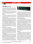
1
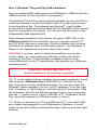
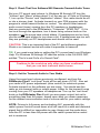
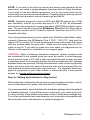
RIGblaster Plus II USB
rig to sound card interface
Owners Manual
RADIO
WEST MOUNTAIN
http://www.westmountainradio.com
1020 Spring City Drive, Waukesha, WI 53186
tel 262.522.6503 fax 262.522.6504
© 2015 West Mountain Radio, All rights reserved.
All trademarks are the property of their respective owners.
Thank for purchasing a RIGblaster Plus II. The Plus II is easy to install
and automatic in operation, It is compatible with virtually every radio
ever made and includes over 150 Amateur Radio programs! A whole
new world of operating experiences awaits you with the availability of all
of these outstanding programs the Plus II offers.
The Plus II is designed to work through only a radio’s mic connector;
thus, making it compatible with almost every radio ever made, and
leaving your radio and PC fully functional as they were before. Use of
the mic jack allows it to operate with fully automatic switching between
the mic and PC, as well as supporting all modes, all software and all of
your radio’s bands. This is a distinct advantage in not being limited by the
design of a radio’s data or aux jack.
The Plus II uses your PC’s sound card system, and does not disable it,
like external audio devices. This makes it possible to use all sound card
programs without having to worry about re-configuring your PC’s audio.
Just plug in two audio cables and everything works correctly without
conflicts or loss of your PC’s normal audio functionality.
The Plus II is several interfaces in one. The USB (Universal Serial
Bus) interface provides PTT control, CW or FSK keying and CAT/CI-V
rig control. The rest of the circuit provides isolated and conditioned
transmit audio.
All Amateur Radio sound card or rig control programs require a standard
serial RS232 interface, and will not work directly with USB. Newer
PCs typically ship without a RS232 serial port. For this reason, the
RIGblaster Plus II has a built in USB-to-serial converter providing PTT,
rig control, and CW or FSK keying via the built-in virtual serial port.
Up until now your ham station system more than likely consisted of only
a radio and an antenna; perhaps also an amplifier. Your new system
will also include a PC with wires going to an AC outlet and possibly the
Internet. VERY IMPORTANT: this “system” must be properly connected
and operating at the same ground potential. The RIGblaster Plus II has
more than adequate ground isolation for proper operation of the audio
and switching. However, it was not designed to work in a system with
a voltage potential caused by a ground loop between two grounds, nor
is it designed to have millions of volts jumping through it from nearby
lightning strikes.
Owner’s Manual
I
You must be certain there is only one physical ground on your station,
as you will now have a radio and a PC. Before you hook up the
RIGblaster Plus II, disconnect any wires that may be between your
radio and your PC, but leave the power cords plugged in. Put an AC
voltmeter between the chassis on your radio and your PC. If you read
more than a fraction of a volt of AC, you have a ground problem! Try
this: take a piece of wire and touch it to the metal PC case and your
radio ground terminal, watch and listen for a spark. You could have
120 VAC of leakage between the house ground and your station ground
— be careful that you do not get a shock.
To eliminate AC ground loops simply plug your radio and PC into the
same AC outlet using the same AC ground point. Consider connecting
your station ground directly to the AC outlet used by your equipment
making your ground at a common single point. A typical commercial
installation would have a buried 00 gauge wire around the perimeter of
the building with all external wires grounded where they come in, and,
the equipment would only have one ground connection to a common
point on the perimeter ground. After doing this simple ground check follow
these instructions step-by-step to make your first computerized contact.
Contents of Package
1-RIGblaster Plus II
(NOTE: COVER IS LOOSE SO YOU MAY EASILY REMOVE IT TO
INSTALL JUMPERS)
1- Accessory Zip Lock bag.
Contents:
4 - Black cover screws #6 sheet metal
8 - Single pin jumper wires
4 - Adhesive pads
1- Pack of Instant Setup Connectors
1 - Microphone Cable (RJ45 to 8 pin screw on)
2 - 1/8” stereo mini plug cables
1 - USB Cable
1 - RIGblaster & RIGtalk DVD
1 - Owner’s manual
II
RIGblaster Plus II
TABLE OF CONTENTS
DIAGRAM:
Connections, controls, and indicators
Page 1
SOUND CARD OPERATION, INSTALLATION AND SETUP
Step 1: Install PSK31 Software: Connect Receive Audio and... Page 4
Step 2: Windows® Plug and Play USB Installation Page 4
Step 3: Install Your Microphone and Test Its Operation on the Air
Page 5
Step 4: Software PTT Setup
Page 6
Step 5: Check that Your Software Will Generate Transmit Audio Tones Page 7
Step 6: Set the Transmit Audio to Your Radio
Page 7
Step 7: Have Fun Working DX
Page 8
CW OPERATION, INSTALLATION AND SETUP
Step 1a: Connect CW Keying Cable
Page 8
Step 2a: Configure the PC and Radio for CW Operation
Page 8
Step 3a: Have Fun Working DX
Page 9
RTTY FSK OPERATION, INSTALLATION AND SETUP
Step 1b: Connect FSK Keying Cable
Page 9
Step 2b: Configure the PC and Radio for RTTY FSK Operation
Page 10
Step 3b: Have Fun Working DX
Page 10
RIG CONTROL CAT/CIV, INSTALLATION AND SETUP
Step 1c: Connecting a CAT or CIV Interface
Page 10
Step 2c: Setting Up the Radio for Rig Control
Page 11
Step 3c: Setting Up Rig Control Software for Rig Control
Page 12
TROUBLESHOOTING Page 13
WARRANTY
Page 15
Owner’s Manual
RIGblaster Plus II connections,
controls, and indicators
1
RIGblaster Plus II
SOUND CARD OPERATION, INSTALLATION AND SETUP
(READ CAREFULLY and PROCEED IN ORDER)
These instructions explain how to use and setup only the
RIGblaster Plus II. Refer to the manual for your radio, the help
files for your PC and third party ham radio software for the other
necessary information.
Step 1: Install PSK31 Software — Connect Receive Audio and Start
Receiving
The RIGblaster is not needed to receive, only transmit, and is
recommended to remain in its enclosure. Please insert the DVD shipped
with this product into your DVD drive. The install menu will automatically
open. Click the “Software Collection” XMIT button. Next click the XMIT
button for PSK31, and finally click XMIT for WINPSK. This is an easy
and simple PSK31 program to get started with.
NOTE: Only an advanced user should install another program or mode.
We recommend not starting with Ham Radio Deluxe! HRD is a rig control
program that will disable the companion sound card program, Digital
Master 780, from working correctly with any standard sound card interface.
Use one of the supplied 1/8” stereo mini plug audio cables to connect
your radio’s speaker output to your PC’s line-in input
(usually blue.)
Your PC’s microphone input
can be used if you have a laptop without
line-in input, but line-in input is preferred. If you have purchased a fixedlevel audio cable made for your model radio from West Mountain Radio,
follow the instructions packaged with the cable.
NOTE: With the appropriate cable you may use any audio output on
any radio (speaker, headphone, record, phone patch or data audio out)
and either of a PC’s audio inputs (line or mic.). The most convenient
connection from the radio is a fixed level audio connection. The line-in
input on a PC is preferred but a microphone input will work as it can be
set correctly from most sound card virtual control panels. Consider your
preferences for operating your radio and computer to best decide which
connection to use.
WARNING: As explained in the preface of this manual be certain your
desktop PC is powered and grounded to the same AC outlet and house
wiring circuit (on the same circuit breaker) as the rest of your ham
station! This is safer and better for many reasons that are both related
and unrelated to the RIGblaster installation.
Owner’s Manual
2
Now tune in some PSK31 signals on: 14.07015, upper side band. You
may use any band but 20 meters always has signals without a good
antenna. If you are an advanced user and are trying another mode,
tune to a frequency appropriate for that mode. There is a digital mode
frequency chart on our DVD for your convenience.
Open your Windows virtual control panel for your sound card input
recording controls. Select and enable whichever input you are using,
mic or line-in. Slide the slider up until you see the receive signals on the
software’s waterfall display.
NOTE: On most PCs you cannot set the input level to any Amateur
Radio sound card program with the playback volume control sliders; you
must use the recording control input sliders. Set the level as described
in the Help files and instructions supplied with the program you are
using. Many ham programs have a utility to directly access the recording
controls, but most of the programs were written before Windows Vista or
7, so those features may not work. Since these are third-party software
tools, the instructions are limited to setting up a RIGblaster Plus II.
Additional instructions for each software program can usually be found in
the software’s Help file.
TIP: Browse the supplied DVD and select “Operating Information”. Listen
to the sound of PSK31 from the recorded sounds. Use the frequency
table for frequencies to operate on the various modes.
If you have a problem with receiving, install another similar PSK31
program to try. If another program works, there was a problem with only
the first program, and now everything is properly connected and ready. If
several programs do not work, then double check your sound card virtual
settings and your audio connections.
TIP: For more information on using and operating a sound card in a
ham station read K1UHF’s “The In’s and Out’s of a Sound Card” in the
October 2003 QST: http://www.westmountainradio.com/pdf/Ins&Outs.pdf
Continue to the next step only after you have
confirmed that you can receive signals
and can hear transmit tones generated.
3
RIGblaster Plus II
Step 2: Windows® Plug and Play USB Installation
Plug the supplied USB cable between the RIGblaster’s USB port and the
USB port on the PC that you plan to use regularly.
The Windows® Plug & Play wizard will automatically run from the DVD to
install the software. It is recommended to allow it to search the Internet
for the best driver files. The software has Microsoft® Logo Certified
drivers and the wizard should find these files the Microsoft® driver update
server if connected to the internet. You can also find the drivers on the
RIGblaster/RIGtalk supplied DVD.
After complete installation of the drivers, the green “USB” LED on the
RIGblaster Plus II will be illuminated, and you may also see the PTT
and CW LEDs flash upon connection. Another indication that the driver
installation is complete when the Windows® balloon “Your Hardware is
Ready to Use” appears at the bottom right of the screen.
CAUTION: If you stop, cancel or abort the installation at any point,
for any reason, you may experience difficulty installing the drivers
correctly in the future. If the automatic installation does not work,
contact Microsoft® or the PC manufacturer that supports your Windows®
operating system.
Continue to the next step only if the
driver installation has properly completed.
TIP: To confirm that the driver installation has properly completed, check
that the green RIGblaster Plus II USB LED is lit. The LED will only
light if you have correctly installed the drivers. You can also check the
Windows® device manager for a list of all PC hardware. To do this, right
click “Computer” or “My Computer” and then left click “Properties”. Click
the “Hardware” tab then the “Device manager” button. Scroll down and
click the “+” symbol next to “Ports (COM and LPT)”. “RIGblaster Plug &
Play” should be assigned a COM port number in this list.
TIP: While you are looking at “Ports (COM and LPT)” note which COM
port number was assigned to your RIGblaster by Windows®. You will
need to know this COM port number later when settin up your ham radio
software.
Owner’s Manual
4
Step 3: Install Your Microphone and Test Its Operation on the Air
The unique feature of the RIGblaster Plus II is that out of the box it will
work with over 2000 different radios. Because different brands of radios
use the same microphone connectors, however, each requires a different
wiring. A simple and elegant solution integrated in the unit is microphone
wiring jumper blocks to allow for universally matching the different wiring
schemes. A set of Instant Setup Connectors (ISCs) are included to get the
wiring right without ever looking at a diagram.
There are six ISCs supplied: three “Round Metal” and three “RJ45 Modular”
for Icom, Yaesu or Kenwood. You will also notice JRC on the Yaesu ROUND
METAL and Alinco, SGC and Elecraft on the Kenwood round metal ISCs.
Out of the six different ISCs, pick the one that matches your radio make,
and also the type or style of connector: “Round Metal” or “RJ45 Modular.
Holding the correct ISC in hand, orient the “front” arrow pointing towards
the front of the RIGblaster Plus II and plug it into the “P1” microphone
jumper block (being careful to line up the two rows of pins with the left edge
of pins, see pictures below). Note that the two right pins are unused on a
RIGblaster Plus II.
Keep the extra ISCs for future use if you get a new radio.
Connect your microphone to the 8 pin round metal connector on front or the
RJ45 to the back. Connect the supplied microphone cable to the unoccupied
connector and the other end to your radio.
5
RIGblaster Plus II
NOTE: RJ45 square Modular mic connector radios are used by plugging
the radio’s mic into the back of the RIGblaster Plus II,screw in the
supplied mic cable onto the front of the RIGblaster, and the RJ45
Modular end into the radio.
NOTE: Unusual or old radios may not be included in the assortment
of ISC’s supplied. They may be able to be hooked up with individual
jumpers. Check our support page for individual wire jumper diagrams for
one of these radios. If you have an accessory adaptor cable for another
style microphone connector follow the instructions supplied with that cable.
It is now time to operate your radio with the mic connected through the
RIGblaster Plus II. Check that the PTT button on the mic activates PTT
on the radio and make certain to get an on the air report, do not only look
at the power meter.
Continue to the next step only if your microphone works exactly
the way it did before, including on the air reports.
Step 4: Software PTT Setup
If you have not previously done so, right click “Computer” in “Start”
(for Vista/7) or “My Computer” icon on your desktop and then left click
“Properties”. Click the “Hardware” tab, then the “Device manager” button.
This shows a list of all PC hardware. Scroll down and click the “+” next to
“Ports (COM and LPT)”. Check which COM port number was assigned
to your RIGblaster Plus II. Remember this number for future use when
setting up every ham radio sound card or rig control program.
Regardless of the program you are using, you must setup and configure
the program for PTT operation by instructing which COM port number
that Windows® assigned to the RIGblaster Plus II.
If the program gives you a choice of using RTS or DTR for PTT, select
RTS. DTR is normally used for CW keying, but may also be used for
RTTY FSK keying (see CW/FSK setup later in this manual).
Tune your radio with it connected to a dummy load and test the PSK
program’s PTT control by activating transmit from the program. Your radio
should indicate PTT (transmit) activation. The radio may or may not indicate
power output depending on how the sound card is set (see the next section).
Continue to the next step only after you have confirmed that you
have PTT activation on both the RIGblaster and the radio.
Owner’s Manual
6
Step 5: Check That Your Software Will Generate Transmit Audio Tones
Set your PC sound card volume. In Windows 98 through XP turn the
“Volume” and “Wave” sliders about ¾ of the way up; in Vista or Windows
7, turn up the “Device” and “Application” sliders. Your radio should be off
or into a dummy load. Activate transmit on your PSK program with the
program’s virtual transmit button or control. You should hear transmit
audio sound (tones) coming from the PC speakers or headphones
that are connected to the RIGblaster’s “Computer” “SPKR OUT” If it is
too loud through the speakers, turn it down using volume knob on the
speakers, not the sound card virtual sliders. If headphones are too loud,
use the sound card sliders to turn down a bit. If headphones are too soft,
they are probably not PC headphones and should not be used.
CAUTION: This is an important test of the PC and software operation.
Weak or no transmit sound will make it impossible to transmit!
TIP: If you need more help on setting the PC’s sound read your Windows
Help. For Windows 98 through XP read the article in the Oct 2003 QST,
entitled “The In’s and Out’s of a Sound Card”.
Continue to the next step only after you have confirmed
that you can hear transmit audio tones.
Step 6: Set the Transmit Audio to Your Radio
Using the sound card volume previously configured, and turn the
RIGblaster Plus II “xmit level” knob all the way down (CCW). Also set
your radio’s RF power adjustment (drive control) to maximum power.
Activate transmit on the software you are using. You should see the
radio go into transmit with no output power. Listen for the transmit tones
coming from your PC speakers or headphones. Turn up the “xmit level”
knob on the RIGblaster Plus II until you see power output, but set to
something less than full power; based upon what you deem necessary
for the desired communication and of course safe for your radio’s ratings.
NOTE: Driving to full power, and activating ALC, especially with the
radio’s power control turned down at all will result in a wide and distorted
signal that is difficult or impossible to copy. Always set the audio drive
from the PC to less than full power with the radio’s power/drive control
set to maximum.
7
RIGblaster Plus II
NOTE: Driving to full power, and activating ALC, especially with the
radio’s power control turned down at all will result in a wide and distorted
signal that is difficult or impossible to copy. Always set the audio drive
from the PC to less than full power with the radio’s power/drive control
set to maximum.
TIP: Once you have the audio transmit power set correctly, you may
adjust your PC speaker volume knob for a comfortable level. If you
change the sound card virtual settings, you will have to re-adjust the xmit
level knob on the RIGblaster Plus II. Never turn down the radio’s power
setting and turn up the sound card.
Step 7: Have Fun Working DX
You are on the air!
CW OPERATION, INSTALLATION AND SETUP
(READ CAREFULLY and PROCEED IN ORDER)
Step 1a: Connect CW Keying Cable
CW cables are available at West Mountain Radio or you may use any
shielded stereo or mono 1/8” mini phone plug to either 1/8” or 1/4”
(depending on your radio’s CW jack) phone plug cable.
Connect the cable from the RIGblaster Plus II “RADIO” “KEY OUT” jack
to the radio’s straight key jack. A paddle input jack will not work. You
must use a straight key jack.
Continue to the next step only if you have connected the
CW cable to a straight key jack.
Step 2a: Configure the PC and Radio for CW Operation
Begin by setting the radio to the CW mode of operation. Select and
install one of the CW programs found on the DVD included or via the
website. Configure for use with the correct COM port as outlined in Step
5 above. Unless you plan to use break in on your radio, the COM port
should be configured for PTT on RTS. Be sure to configure and setup the
software to key CW on the same COM port using DTR.
Owner’s Manual
8
NOTE: If you do not set up the software for RTS to do PTT control, you
will have to set the radio for break-in or semi-break-in CW operation;
both options will properly.
Test CW operation by transmitting with the CW software. The radio
should transmit CW and the RIGblaster Plus II red CW keying LED
indicator should flash with the dots and dashes. The PTT should come on
steadily in transmit if you have configured the software for that on RTS.
Step 3a: Have Fun Working DX
You are on the air with CW. You can now type CW with your keyboard!
Keyboard CW operation is great for CW contesting but nothing beats a
real key for regular CW QSOs.
RTTY FSK OPERATION, INSTALLATION AND SETUP
(READ CAREFULLY and PROCEED IN ORDER)
Step 1b: Connect FSK Keying Cable
FSK keying cables are available at West Mountain Radio. The “KEY
OUT” jack on the RIGblaster Plus II may be used for FSK keying instead
of CW keying. Understand that AFSK operation using the sound card for
transmit in LSB has many advantages. However, be advised that the only
advantage may be with a radio that has better AGC operation because of
IF filters that are only available for RTTY. Most radios allow for the same
filters set with the radio in LSB instead of RTTY mode, or the last stage
IF filters have no effect on AGC performance.
Connect the cable from the RIGblaster Plus II “KEY OUT” jack to the
radio’s FSK keying jack. The 1/8 mini phono plug “tip” of the keying jack
goes to the FSK keying pin and the “sleeve” goes to common or ground
on the radio’s RTTY FSK connector. A custom cable for your radio
may be purchased at West Mountain Radio or make one following the
diagrams in your radio’s manuals.
To test this cable, plug it into the radio’s jack only and put the radio in
the RTTY mode with the monitor on. Set the radio manually into transmit
and sort the 1/8” plug from tip to sleeve and listen to the monitor to be
sure that the frequency shifts. If it does, you may plug the cable into the
RIGblaster’s “KEY OUT” jack.
Continue to the next step only if you have connected the
CW cable to a straight key jack.
9
RIGblaster Plus II
Step 2b: Configure the PC and Radio for RTTY FSK Operation
Presently, to our knowledge the only RTTY software that works with the
RIGblaster Plus II or any USB-to-serial interface is MMTTY, and that
only by using the author’s EXTFSK extension. The reason is that USBto-serial interfaces will not go down to 45 baud.
Follow the MMTTY Help files for setting up the program using the
EXTFSK extension to use the correct COM port with PTT on RTS and
FSK keying on DTR.
Once configured, transmit with MMTTY and watch the PTT and CW
LEDs. The PTT LED should be on steadily and the CW LED should
flicker with the RTTY. Confirm with the radio’s monitor that the FSK
output sounds like RTTY.
You will also have to make sure that your mark and space tones are
correct by setting the radio and/or the software so that transmit and
receive mark and space tones are correct. The only easy way to do
this is on the air.
Step 3b: Have Fun Working DX
You are on the air with FSK RTTY.
RIG CONTROL CAT/CIV, INSTALLATION AND SETUP
(READ CAREFULLY and PROCEED IN ORDER)
Step 1c: Connecting a CAT or CIV interface
The RIGblaster Plus II has a built-in USB-to-Serial converter with TTL (5
volt logic) output. It may be used with any radio (CAT or CI-V controlled)
that requires an RS232 to TTL level converter. This includes most Icom,
Ten Tec (CI-V) and smaller or newer Yaesu (CAT) radios.
NOTE: If your radio has a DB-9/RS-232 rig control jack, you do not need,
nor can you use, the TTL level rig control interface inside the RIGblaster
Plus II. These radios require a direct connection to a PC’s RS-232 COM
port. If your PC has a DB-9/RS-232 COM port, you may purchase a DB-9
cable; if the PC does not have RS-232, a USB-to-Serial interface cable is
also available for purchase. If you do wish to use the rig control feature
of this RIGblaster Plus II, you may order a pre-wired cable from West
Mountain Radio for rig control.
Owner’s Manual
10
NOTE: If you wish to do both rig control and sound card operation at the
same time, you need a single program that does both of those functions.
If you wish to use two different programs, one for rig control and one for
sound card you must have two interfaces. Programs that do both rig control
and sound card operation include Hamscope and MixW.
NOTE: Separate programs such as HRD and DM780 require two COM
port interfaces, one for rig control and one for PTT or CW, as Windows®
will not allow two programs to access the same USB COM port at the same
time. The work around is to set the RIGblaster Plus II to the VOX mode to
permanently connect the PC audio for transmit, and then use CAT or CI-V
transmit activation.
If you have purchased a rig control cable from West Mountain Radio cable,
connect it between the RIGblaster Plus II “RIG”, “RIG CTL” jack and the
radio’s CAT or remote (CI-V) jack as described in the instructions that came
with the custom cable for your radio. Make sure the radio end of a CI-V
cable is correct. If you wish to make your own cable you diagrams are as
follows in this manual or available on our support page.
CAUTION: When interfacing electronics between various products that
are connected to the outside world you must be careful to avoid damage
due to ground loops. A PC with a case grounded through its line cord and
a radio grounded to an antenna system can have tremendous AC leakage
between these two grounds. During a thunderstorm with a near-by lightning
strike, not just a direct hit, several thousand volts can be induced into the
loop antenna formed by this type of ground loop. It is important that every
piece of equipment in your ham station is connected with a star ground
system to a single point ground (no loops).
Step 2c: Setting Up the Radio for Rig Control
Most radios have settings for the rig control communications interface, which
may include baud rate, parity, stop bits and CI-V addresses.
It is recommended to check that the radio has these settings set to the default
or standard settings. Consult the owner’s manual for your radio to be sure
it is set correctly to the default and make a note of what these settings are.
Turn off any automatic baud rate detection as it is usually incompatible with
the automatic baud rate detection in software programs.
12
RIGblaster Plus II
Step 3c: Setting Up Rig Control Software for Rig Control
Since radios have settings for the rig control communications, it is logical
that the software must be set to match those settings exactly. Most rig
control programs will use the radio default settings if you select the exact
model radio. Be aware, for example, if you have an IC706MKIIG and you
set your software to an IC706MKII (NO “G”) the rig control will not work at
all! This is true of other series of radios also.
Regardless of which rig control program you have installed, you will have
to configure the program for the COM port number of the RIGblaster Plus
II to ensure an exact match for all of the communications settings.
Any one item set incorrectly will totally prevent rig control from working.
Every communication setting in the software must exactly match the settings
for and in the radio.
With rig control set up and modern logging software you will never have
to type your frequency into your PC log again and you can jump to a DX
cluster spot instantly.
Yaesu 6 pin DIN CAT control cable wiring
Yaesu TTL Control
(Viewed from the rear)
TXD
GND
RXD
RIGblaster
CTL IN/OUT
Yaesu 8 pin mini DIN CAT control cable wiring
RIGtalk to Yaesu TTL Standard size DIN CAT cable wiring
TXD
GND
8 pin mini DIN to
radio’s ACC jack
Two conductor shielded
cable is recommended.
3.5mm - 1/8”
stereo mini
phone to
RIGtalk
(Viewed from the rear)
Icom or Ten Tec CI-V remote cable wiring
TXD
TXD
RXD
ICOM CI-V
REMOTE GND
Owner’s Manual
GND
12
RXD
RXD
RIGblaster
CTL IN/OUT
TROUBLESHOOTING
If you have installed the RIGblaster Plus II, step-by-step, from this manual
you need not go back to a previous step. The problem is isolated to the
step that you had a problem on.
If you contact us for support please be sure you know which step of this
manual you cannot go any further on before calling or writing.
Most RIGblaster problems usually have nothing to do with the RIGblaster
or how it is connected. They are typically software related and can only
be fixed with a mouse. Make sure you have your sound card set properly
and that you understand the operation of the necessary controls out of over
forty virtual controls most sound cards have. Also be sure that you have
the COM port settings in your ham radio program correct. If you cannot
get a program to work try another program, there are over 100 ham radio
sound card programs and over 50 rig control programs.
TYPICAL PROBLEMS:
1) The software has no receive signal displayed because the sound card
input is not turned on or up. Use the recording adjustments on Windows®
not the playback volume controls. Most PCs have duplex sound cards and
receive signal input levels cannot be adjusted from the Windows® playback
volume panels, only from the recording panels.
2) The ham radio sound card software is not set to do PTT on the correct
serial port. All programs must be configured to control PTT of the RIGblaster
and the radio using the RTS line of the serial port. You cannot transmit
automatically unless you do this!
TIP: Windows® will mysteriously change the COM port assignment. If you
are having a problem check the COM port number assignment in your
Windows control panel.
TIP: You are using a rig control program to activate transmit, such as Ham
Radio Deluxe. You MUST activate PTT on RTS with a sound card program,
such as Digital Master 780
TIP: The sound card is set too low because the PC speakers are too loud.
Turn down your PC speakers and turn up your sound card.
13
RIGblaster Plus II
TIP: The RF power / drive control on the radio is not set to maximum causing
the PC not to have enough audio to drive the radio even to half output.
TIP: The RF power / drive control on the radio is not set to maximum causing
the drive stages and ALC to distort your signal causing it to be wide and
distorted. Set the RF drive to maximum and turn down the audio drive to
the desired RF power level.
TIP: Low impedance headphones or speakers are loading down the audio
output from the sound card. Disconnect them or replace them with amplified
PC speakers or PC headphones.
Please understand that the RIGblaster Plus II will not work if the software
and PC do not work. Make sure that you have your software operating
properly and your sound card adjusted properly to expect your station with
the RIGblaster Plus II to work. You must read the documentation (Help
files) that comes with the software. With over 150 RIGblaster compatible
programs, we cannot include software instructions in this manual. Also we
did not write the software and we cannot properly support it. It is suggested
that if experiencing software problems, try a different program.
If you have audio problems with two or more sound card programs, not
necessarily ham radio programs, you may have a problem with your
Windows® sound card driver software installation, not your sound card
hardware.
For additional support information go to:
http://www.westmountainradio.com/supportpnp.htm
NOTE: If you contact us for support we must have the number of the
step of this manual that you ran into a problem on. We may not be
able to help you without this information.
It is best to call us while you are at your station rather than try to
communicate with us by email. Our support desk is available 8:30 AM
to 5 PM Central Time Zone, Monday through Friday.
Owner’s Manual
14
RIGblaster Plus II Warranty
RIGblaster Plus II is warranted against failure due to defects in workmanship
or materials for one year after the date of purchase from West Mountain
Radio. Warranty does not cover damage caused by abuse, accident,
misuse, improper or abnormal usage, failure to follow instructions, improper
installation, alteration, lightning, or other incidence of excessive voltage or
current. If failure occurs within this period, return the RIGblaster Plus II or
accessory to West Mountain Radio at your shipping expense. The device
or accessory will be repaired or replaced, at our option, without charge,
and returned to you at our shipping expense. Repaired or replaced items
are warranted for the remainder of the original warranty period. You will be
charged for repair or replacement of the RIGblaster Plus II or accessory
made after the expiration of the warranty period.
The DVD of Radio Amateur Software Collection is excluded from any and
all warranties by West Mountain Radio. Note that the programs have been
provided as shareware or freeware by the software authors to the amateur
radio community for their use and enjoyment. The DVD is to be used at
your own risk.
West Mountain Radio shall have no liability or responsibility to customer
or any other person or entity with respect to any liability, loss, or damage
caused directly or indirectly by use or performance of the products or arising
out of any breach of this warranty, including, but not limited to, any damages
resulting from inconvenience, loss of time, data, property, revenue, or profit,
or any indirect, special incidental, or consequential damages, even if West
Mountain Radio has been advised of such damages.
Except as provided herein, West Mountain Radio makes no express
warranties and any implied warranties, including fitness for a particular
purpose, are limited in duration to the stated duration provided herein.
www.westmountainradio.com
1020 Spring City Drive, Waukesha, WI 53186
tel 262-522-6503 fax 262-522-6504
15
RIGblaster Plus II
1N4148
PMEG2005ET
PMEG2005ET