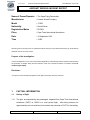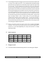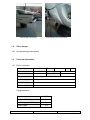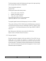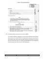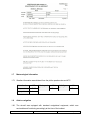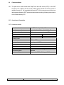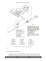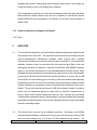
1
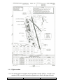
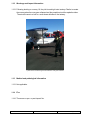
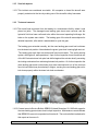
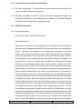
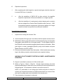
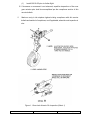
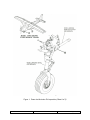
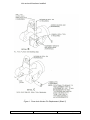
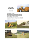
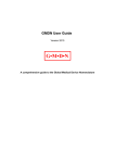
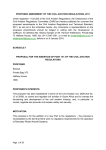
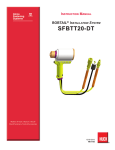
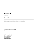
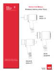
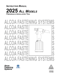
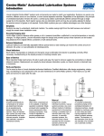
Form Number: CA 12-12b
Accident and Incident Investigation Division
Section/division
AIRCRAFT SERIOUS INCIDENT REPORT AND EXECUTIVE SUMMARY
Reference:
Aircraft
Registration
Type of Aircraft
ZS-PMY
10/09/2010
Date of Incident
Cessna 172RG (Aeroplane)
Time of Incident
Commercial
Pilot-in-command Flying
Experience
Total Flying Hours
Age
1245Z
Private
Type of Operation
Pilot-in-command Licence Type
CA18/3/2/0806
19
246,2
Last point of departure
Cape Town International Aerodrome (FACT)
Next point of intended landing
Cape Town International Aerodrome (FACT)
Licence Valid
Yes
Hours on Type
35,3
Location of the incident site with reference to easily defined geographical points (GPS readings if possible)
Cape Town International Aerodrome, Taxiway Charlie
Meteorological Information
Surface wind 135°/15 kt, temperature 17 °C, visibility +10 km
Number of people on board
1+2
No. of people injured
0
No. of people killed
0
Synopsis
The pilot, accompanied by two passengers, departed from Cape Town International Aerodrome on a
local private flight. After being airborne for approximately one hour and forty-five minutes they
returned to FACT for the landing.
Prior to landing the pilot selected the landing gear down and normal operation was confirmed by the
green ‘gear down’ light illuminating. After approximately 30 m the nose landing gear had touched
down, the pilot noticed that the propeller made contact with the runway surface several times. He
immediately applied back pressure to the control column to raise the nose of the aircraft. Following
this intervention, the nose wheel touched down for a second time without any further problem, and the
aircraft continued to roll down the runway. However, as the pilot turned right onto taxiway Charlie in
order to vacate runway 19, the nose landing gear collapsed and the propeller struck the asphalt
surface.
The aircraft came to rest in a nose-down attitude, whereafter the pilot secured the aircraft and the
three occupants disembarked from the aircraft unassisted.
Probable Cause
The nose landing gear (NLG) collapsed during taxiing due to the failure of one of the NLG actuator
down lock pins during operation.
IARC Date
CA 12-12b
Release
Date
25 MAY 2010
Page 1 of 25
Section/division
Accident and Incident Investigations Division
Form Number: CA 12-12b
AIRCRAFT SERIOUS INCIDENT REPORT
Name of Owner/Operator
: The Cape Flying Partnership
Manufacturer
: Cessna Aircraft Company
Model
: 172RG
Nationality
: South African
Registration Marks
: ZS-PMY
Place
: Cape Town International Aerodrome
Date
: 10 September 2010
Time
: 1245Z
All times given in this report are Co-ordinated Universal Time (UTC) and will be denoted by (Z). South African
Standard Time is UTC plus 2 hours.
Purpose of the Investigation:
In terms of Regulation 12.03.1 of the Civil Aviation Regulations (1997) this report was compiled in the interest of
the promotion of aviation safety and the reduction of the risk of aviation accidents or incidents and not to
establish legal liability.
Disclaimer:
This report is produced without prejudice to the rights of the CAA, which are reserved.
1.
FACTUAL INFORMATION
1.1
History of flight
1.1.1 The pilot, accompanied by two passengers, departed from Cape Town International
aerodrome (FACT) at 1045Z on a local private flight.
After being airborne for
approximately one hour and forty-five minutes they returned to FACT for the landing.
CA 12-12b
25 MAY 2010
Page 2 of 25
1.1.2 The prevailing wind at the time being from the south-east, the pilot was cleared to land
on runway 19 by air traffic control (ATC). Prior to landing the pilot selected the landing
gear down and normal operation was confirmed by the green ‘gear down’ light coming
on in the cockpit. The pilot indicated that he touched down on the main landing gear
and kept the nose landing gear off the ground until elevator effectiveness was lost.
Approximately 30 metres after the nose wheel had touched down, the pilot noticed that
the nose started dropping and the propeller struck the runway surface several times.
He immediately applied back pressure to the control column and managed to raise the
nose of the aircraft. Once the nose wheel settled down on the runway for the second
time he continued to taxi down the runway without any further problem. As they turned
right onto taxiway Charlie in order to vacate runway 19, the nose landing gear
collapsed and the propeller struck the asphalt surface. The pilot then proceeded to
secure the aircraft. According to the pilot there was no ‘gear unsafe’ audio warning
that was activated during the sequence, either while they were on the runway or as the
nose landing gear collapsed during the turn.
1.1.3 Nobody on board the aircraft was injured, and the three occupants disembarked
unassisted. The aircraft was recovered by aerodrome rescue and fire-fighting (ARFF)
personnel as it was obstructing/blocking the runway and was taken to a nearby
maintenance facility.
1.2
Injuries to persons
Injuries
1.3
Pilot
Crew
Pass.
Other
Fatal
-
-
-
-
Serious
-
-
-
-
Minor
-
-
-
-
None
1
-
2
-
Damage to aircraft
1.3.1 The aircraft sustained substantial damage when the nose landing gear collapsed.
CA 12-12b
25 MAY 2010
Page 3 of 25
Visible damage to the propeller
1.4
Visible damage to the nose gear doors
Other damage
1.4.1 No other damage was caused.
1.5
Personnel information
1.5.1 Pilot-in-command
Nationality
South African
Gender
Male
Age
Licence number
*****************
Licence type
Commercial
Licence valid
Yes
Type endorsed
Yes
Ratings
Night rating
Medical expiry date
30 September 2010
Restrictions
None
Previous accidents
None
19
Flying experience
Total hours
CA 12-12b
246,2
Total past 90 days
49,5
Total on type past 90 days
22,9
Total on type
35,3
25 MAY 2010
Page 4 of 25
1.6
Aircraft information
1.6.1 Airframe
Type
Cessna 172RG
Serial no.
172RG-0218
Manufacturer
Cessna Aircraft Company
Year of manufacture
1980
Total airframe hours (at time of incident)
4 652,10
Last MPI (hours & date)
4 645,10
Hours since last MPI
7,0
C of A (issue date)
3 September 2004
C of R (issue date) (present owner)
2 December 2004
Operating categories
Standard Part 135
30 June 2010
Engine
Type
Lycoming O-360-F1A6
Serial no.
L-27628-36A
Hours since new
2 379,40
Hours since overhaul
179,40
Propeller
Type
McCauley 32D-34C-220B
Serial No.
000385
Hours since new
1 238,50
Hours since overhaul
998,30
1.6.2 Record of previous major defects and damage sustained
Date
Airframe hours
Brief description of defect
20/04/1982
977,9
Nose gear retracted on take-off. Firewall forward damaged.
11/10/1988
1 745,0
Damage to front section, cabin floor and l/h wing.
20/09/1991
2 231,0
Damage to front section, nose gear doors, cowl flaps.
18/05/2005
3 653,1
Nose gear failure, propeller strike.
Source: Aircraft Airframe Logbook pages 4 and 5.
CA 12-12b
25 MAY 2010
Page 5 of 25
The airframe logbook contains the following entry with regard to the repairs pertaining
to the nose gear failure incident on 18 May 2005:
“Type of maintenance performed.
Propeller Strike:
Following parts replaced after landing incident:
1.
Fork end, Part number: 0770-0770
2.
Damper, Part number: 1442114-1
3.
Clamp, Part number: 2243028-1
Sheet metal repairs carried out to nose gear wheel well.
Signed off by AMO No. 221 on 5 October 2005.”
The propeller logbook contains the following entry in the form of a CRMA:
“The propeller, McCauley 32D-34C-220B, Serial No. 000385 had been overhauled in
accordance with the relevant manual No. 780630 REV 6, SPM 100-1, BOM 100-1 REV
1 and Appendix 1 of the General Maintenance Rules Pages GMR-66 & GMR-67,
Section 5.1.
Major Replacements: New blades, above serials (04-1950 Mc Prop)
Repairs carried out: Standard Overhaul Procedures.”
1.6.3 Nose gear inspection
During the maintenance inspection, which was certified on 30 June 2010, the nose
landing gear of the aircraft was inspected in accordance with the aircraft
manufacturer’s service schedule (see attached document below, which was extracted
from the work pack). The inspection requires a detailed inspection of the nose landing
gear, which include checking for main gear down lock engagement. It does not require
the down lock pins to be inspected.
CA 12-12b
25 MAY 2010
Page 6 of 25
1.6.4 Certificate relating to maintenance of an aircraft (CRMA)
The certificate relating to maintenance of an aircraft (see attached document below)
that was issued for the aircraft ZS-PMY following the last maintenance inspection prior
to the accident flight reflects that the nose gear inspection was carried out as required
and that no faults were found. The system operated satisfactorily (the maintenance
inspection requires five fault free cycles of the landing gear).
CA 12-12b
25 MAY 2010
Page 7 of 25
1.7
Meteorological information
1.7.1 Weather information was obtained from the pilot’s questionnaire and ATC.
Wind direction
135°
Wind speed
15 kt
Visibility
Temperature
17 °C
Cloud cover
Clear
Cloud base
Dew point
1.8
+10 km
Clear
Unknown
Aids to navigation
1.8.1 The aircraft was equipped with standard navigational equipment, which was
serviceable and functioning accordingly at the time of the incident.
CA 12-12b
25 MAY 2010
Page 8 of 25
1.9
Communications
1.9.1 The pilot was in radio contact with Cape Town air traffic control (ATC) on the VHF
frequency 118,1 MHz at the time of the incident as the aircraft was in the process of
vacating runway 19. He immediately informed ATC of the occurrence once the nose
landing gear collapsed. ARFF personnel responded accordingly following the activation
of the crash alarm by ATC.
1.10
Aerodrome information
1.10.1 Aerodrome details
CA 12-12b
Aerodrome location
7 nm SE of the city of Cape Town
Aerodrome co-ordinates
South 33° 58’16.93” East 018° 36’15.45”
Aerodrome elevation
151 feet above mean sea level (AMSL)
Runway designations
01/19
16/34
Runway dimensions
3 200 x 61 m
1 701 x 46 m
Runway used
19
Threshold elevation
147 feet AMSL
Runway slope
Downslope of - 0.03%
Runway grooved
No
Runway surface
Asphalt
Approach facilities
VOR, DME, NDB, runway lights, PAPIs, ILS
Aerodrome status
Licensed
License validity
1 September 2009 to 31 August 2010
25 MAY 2010
Page 9 of 25
1.11
Flight recorders
1.11.1 The aircraft was not equipped with a flight data recorder (FDR) or a cockpit voice
recorder (CVR), nor was it required by regulation to be fitted to this type of aircraft.
CA 12-12b
25 MAY 2010
Page 10 of 25
1.12
Wreckage and impact information
1.12.1 Following landing on runway 19, the pilot turned right onto taxiway Charlie to vacate
the runway when the nose gear collapsed and the propeller struck the asphalt surface.
The aircraft came to a halt in a nose-down attitude on the taxiway.
A photo of the aircraft being recovered with the nose gear retracted.
1.13
Medical and pathological information
1.13.1 Not applicable.
1.14
Fire
1.14.1 There was no pre- or post-impact fire.
CA 12-12b
25 MAY 2010
Page 11 of 25
1.15
Survival aspects
1.15.1 This incident was considered survivable. All occupants on board the aircraft were
properly restrained at the time by making use of the aircraft’s safety harnesses.
1.16
Tests and research
1.16.1The aircraft was recovered from the taxiway to a maintenance facility, where it was
placed on jacks. The damaged nose landing gear doors were removed, and the
hydraulic fluid level was confirmed to be within the normal operating limit/range. No
leaks on the system were visible. The landing gear of the aircraft was subjected to
detailed inspection, after which it was decided to cycle the gear.
The landing gear extended normally, but the nose landing gear would not lock down
into the down lock position. Nevertheless the green ‘gear down’ warning light went out.
The landing gear safe light was tested and found serviceable. The audio warning
system, although soft, was operational. Upon further inspection it was found that one
of the NLG actuator down lock pins had shifted against the actuator shaft, preventing
the locking mechanism from achieving its down lock position. On further inspection the
nose landing gear down lock actuator pins were examined and one of the pins was
found to have failed (see photo below) in fatigue, causing the nose landing gear not to
lock down properly within the down lock hook mechanism.
A view of the actuator with the down lock pins installed.
A view of the failed down lock pin contained in the housing.
1.16.2 Cessna issued a Service Bulletin SEB95-20 dated December 29, 1995 with regard to
the nose landing gear actuator down lock pin inspection. Maintenance records indicate
that SEB95-20 was not incorporated on this aircraft. The service bulletin is attached to
this report as Annexure A.
CA 12-12b
25 MAY 2010
Page 12 of 25
1.17
Organisational and management information
1.17.1 This was a private flight. The aircraft was hired by the pilot from a flying club for his
private use under a hire and fly agreement.
1.17.2 According to available records the aircraft maintenance organisation (AMO) that
certified the last MPI prior to the accident was in possession of a valid AMO Approval
certificate that was issued by the regulating authority.
1.18
Additional information
1.18.1 Landing gear system
Quoted from: Cessna 172RG Service Manual
General Description:
“Retraction and extension of the landing gear is accomplished by a hydraulicallypowered system, integrated with electrical circuits which help control and indicate gear
position. Retraction and extension of the landing gear incorporates a nose gear
actuator and two main gear actuators which control the main gear struts through a
sector gear arrangement. The nose gear doors are mechanically-operated. The doors
are closed with the gear retracted and are open with the landing gear extended. The
main gears have no doors. Hydraulic fluid is supplied to the landing gear actuating
cylinders by an electrically-powered power pack assembly, located in the cabin,
forward of the center console. The hydraulic reservoir is an integral part of the power
pack assembly. Gear selection is accomplished manually by moving a gear selector
handle, located immediately left of the center, in the switch panel. It is necessary to
pull out on the gear selector to move the handle up or down. For emergency extension
of the gear, the selector handle must be in the DOWN position before the hand pump
will energise the system. A pressure switch is mounted on the power pack. The switch
opens the electrical circuit to the pump solenoid when pressure in the system increases
to approximately 1500 psi. The pressure switch will continue to hold the electrical
circuit open until pressure in the system drops to approximately 1000 psi. This will
occur whether the gear selector handle is in either the UP or DOWN position. During a
normal cycle, landing gear extended and locked can be detected by illumination of the
DOWN indicator (green) light. The nose gear squat switch, actuated by the nose gear,
prevents gear retraction whenever the nose gear is compressed by the weight of the
aircraft. The GEAR UNSAFE (red) light is on anytime the gear is in transit (retracted
CA 12-12b
25 MAY 2010
Page 13 of 25
cycle), or whenever system pressure drops below 1000 psi with the safety (squat)
switch closed.
Nose Gear System:
Description:
The nose gear consists of a pneudraulic shock assembly, mounted in a trunnion
assembly, a nose gear steering system with bungee, a shimmy dampener, nose wheel,
tire and tube, hub cap, bearings, seals and a double-acting hydraulic actuator for
extension and retraction. A claw-like hook on the actuator serves as a down-lock for
the nose gear. Stop bolts, located in the lower aft well, prevent inadvertent nose gear
collapse.
Operation:
The nose gear shock strut is pivoted at the firewall. Retraction and extension of the
nose gear is accomplished by a double-acting hydraulic cylinder, the forward edge of
which contains the nose gear down-lock. Initial action of the cylinder disengage the
down-lock before retraction begins. As the strut moves into the gear well, the forward
side of the nose gear fork boss contacts an actuator assembly, causing the doors to
close. The nose gear is held in the UP position by hydraulic pressure”.
CA 12-12b
25 MAY 2010
Page 14 of 25
1.18.2 Similar type of serious incident
According to the SACAA accident database a similar type of serious incident occurred
at Bloemfontein aerodrome on 28 July 2006, involving a Cessna T210K. The pilot
CA 12-12b
25 MAY 2010
Page 15 of 25
indicated that he had a landing gear down indication (green light) in the cockpit, but
during the landing roll the nose landing gear collapsed.
The investigation found that one of the nose landing gear down lock pins had failed.
What made this incident different from the one in question is that Cessna Service
Bulletin SEB95-20 was incorporated on this aircraft, yet the down lock pin failed in a
similar mode.
1.19
Useful or effective investigation techniques
1.19.1 None.
2.
ANALYSIS
2.1
The aircraft was released for service following a detailed maintenance inspection that
was certified on 30 June 2010. The inspection was conducted in accordance with the
aircraft manufacturer’s maintenance schedule, which required that a detailed
inspection be performed on several nose landing gear components. The maintenance
schedule, however, does not require that the two down lock pins fitted to the nose
landing gear actuator be inspected. Cessna Service Bulletin (SB) SEB95-20 was an
option by the aircraft manufacturer to the applicable/affected aircraft owners, which
indicates that the manufacturer had introduced an improvement to the original design
by issuing the SB and informed all aircraft owners that failure to comply with the SB
could result in the nose landing gear not locking in the down position and collapsing.
By adhering to the SB, the risk of an unforeseen nose landing gear collapse could be
avoided, although no guarantees could be associated with compliance with such a
bulletin. The aircraft manufacturer issues an SB in the interest of safety, but has no
control over the operational aspects to which such an aircraft is exposed while in
service, which could include landing and taking off from licensed and unlicensed
runways/landing strips/aerodromes, hard landings, excessive braking and exceeding
the design envelope/limitations of the aircraft, especially owing to maximum allowable
take-off and landing weight.
2.2
This incident was, however, not an isolated occurrence. According to the SACAA
accident/incident database a similar type of occurrence was recorded on 28 July 2006
when the nose landing gear of a Cessna T210K collapsed during landing. The
CA 12-12b
25 MAY 2010
Page 16 of 25
investigation concluded that one of the NLG actuator down lock pins had failed and as
a result the nose landing gear collapsed during the landing roll. Although not the same
model of aircraft the one in question, the operation of the landing gear system was the
same. It was found that Cessna Service Bulletin SEB95-20 was incorporated on the
Cessna T210K, yet the nose landing gear collapsed.
2.3
The down lock pins on the nose landing gear actuator are on-condition items, and if not
properly inspected/maintained they might fail in operation without prior notice.
Although this aircraft was subjected to a maintenance inspection shortly prior to this
failure and only 7 flying hours were recorded, it is considered highly unlikely that the
fatigue cracking that might have been present at the time would have been picked up
by maintenance personnel, as it was not a schedule inspection requirement to inspect
these pins for cracks nor to have them subjected to any form of non-destructive crack
testing procedure during maintenance. The pin was found to have failed in fatigue.
2.4
Available information indicates that this aircraft was involved in four previous incidents
related to the nose landing gear (tabled in paragraph 1.6.2 of this report) over the
period 20 April 1982 to 18 May 2005. None of these occurrences appears on the
SACAA accident/incident database, even though it would appear that the aircraft
sustained substantial damage during these incidents. The aircraft had been in service
for nearly five years following the last repair, with 998,30 flying hours being logged
subsequently. It was, however, not possible to draw any comparison between the
previous incident dated 18 May 2005 and the one in question due to limited information
being available on the previous incident (contained to the logbook entry; type of
maintenance performed).
3.
CONCLUSION
3.1
Findings
3.1.1 The pilot was the holder of a valid commercial pilot’s licence and had the aircraft type
endorsed in his logbook.
3.1.2 The pilot was the holder of a valid aviation medical certificate that was issued by an
approved CAA medical examiner.
3.1.3 The aircraft was maintained in accordance with the approved maintenance schedule
and was in possession of a valid certificate of airworthiness at the time of the incident.
CA 12-12b
25 MAY 2010
Page 17 of 25
3.1.4 The CRMA of the aircraft was valid.
3.1.5 The aircraft had flown 7,0 hours since the last maintenance inspection was certified.
3.1.6 Cessna Service Bulletin SEB95-20 dated December 29, 1995 was not incorporated on
this aircraft.
3.1.7 The flight was operated as a private flight (Part 91) under VFR rules.
3.1.8 The was an indistinct landing gear unsafe alarm prior to the nose landing gear collapse
which probably could not be heard by the pilot.
3.2
Probable cause/s
3.2.1 The nose landing gear (NLG) collapsed following touchdown due to the failure of one
of the NLG actuator down lock pins.
3.3
Contributory factor/s
3.3.1 Cessna Service Bulletin SEB95-20 dated December 29, 1995 was not incorporated on
this aircraft; therefore the risk of this known problem was not mitigated.
4.
SAFETY RECOMMENDATIONS
4.1
It is recommended that the Director of Civil Aviation in collaboration with the
Airworthiness Division introduce a life limit or non destructive test procedure at regular
intervals on the down lock pins to ensure that safety is not compromised and to prevent
a re-occurrence of this nature.
5.
APPENDICES
5.1
Annexure A (Cessna Service Bulletin SEB95-20 dated December 29, 1995)
Report reviewed and amended by the Advisory Safety Panel 18 January 2011.
-END-
CA 12-12b
25 MAY 2010
Page 18 of 25
ANNEXURE A
Cessna Service Bulletin SEB95-20: (Shortened version)
Effectively
Models
172RG
F182RG
R182
TR182
210
T210K/L/M/N/R
P210N/R
*NOTE: The above list of models is a basic summary of the models affected by this
Service Bulletin, which basically includes all single piston engine Cessna models with
retractable landing gear.
Purpose
Reports have been received of the nose landing gear actuator down lock pins cracking
and/or failing. The pins have failed at a circumferential groove that is used to secure
the pin in the actuator bearing end. To assist in preventing this condition from
occurring, an inspection should be accomplished to determine the security of the down
lock pins. Actuators with down lock pins that are found to be loose should have the
pins replaced according to the criteria in this service bulletin. Failure to comply with
this service bulletin can potentially result in the nose landing gear to not lock in the
down position and possibly collapse.”
Compliance is recommended.
A.
Initial Inspection:
Should be accomplished within the next 200 hours of operation or 12 months,
whichever occurs first.
CA 12-12b
25 MAY 2010
Page 19 of 25
B.
Repetitive Inspections:
1.
After completing the initial inspection, repeat at each gear retraction check not
to exceed 200 hours of operation.
2.
a.
After the installation of SK210-155 (or later revision), the repetitive
inspection requirement of this service bulletin is no longer required.
b.
After the installation of a replacement actuator bearing end or actuator
that was shipped from Cessna Parts Distribution after January 1, 1996,
the repetitive inspection requirement of this service bulletin is no longer
required as these incorporate the modified pin installation”.
Accomplishment Instructions
1.
Inspect Nose Landing Ger Actuator Pins:
A. Jack the airplane off the ground in accordance with the airplane service manual.
B. With Master Switch in the OFF position and the hydraulic pump circuit breaker
disengaged, select GEAR UP on the gear handle. Turn the Master Switch to
the ON position and momentarily engage hydraulic pump circuit breaker. When
gear begins to retract, disengage hydraulic pump circuit breaker and place
Master Switch to the OFF position.
C. Disconnect all electrical power from the airplane. Attach maintenance warning
tags to the battery connector and external power receptacle stating:
WARNING: DO NOT CONNECT ELECTRICAL POWER – MAINTENANCE IN
PROGRESS.
D. Support nose wheel so pressure is off the actuator pins.
E. (Refer to Figure 1, Sheet 1, Detail A). Visually inspect actuator pins while
physically attempting to rotate and/or move actuator pins about all three axes in
the bearing end. No movement is allowed, as pins are a press fit.
NOTE: It is permissible to use locking-type needle nose pliers to check for
actuator pin looseness/movement, provided serrated teeth are removed from
pliers and no galling marks are transmitted to the actuator pins.
F. If any looseness or movement is observed:
CA 12-12b
25 MAY 2010
Page 20 of 25
(1)
Install SK210-55 prior to further flight.
G. If looseness or movement is not observed, repetitive inspections of the nose
gear actuator pins shall be accomplished per the compliance section of this
service bulletin.
2.
Make an entry in the airplane logbook stating compliance with this service
bulletin and method of compliance, and if applicable, when the next inspection is
due.
Figure 1. Down lock Actuator Pin Inspection (Sheet 1)
CA 12-12b
25 MAY 2010
Page 21 of 25
Figure 1. Down lock Actuator Pin Inspection (Sheet 1of 2)
CA 12-12b
25 MAY 2010
Page 22 of 25
Accomplishment Instructions
1.
Remove and Disassemble Nose Gear Actuator From Airplane:
A. Jack the airplane off the ground in accordance with the airplane service manual.
B. With Master Switch in the OFF position and the hydraulic pump circuit breaker
disengaged, select GEAR UP on the gear handle. Turn the Master Switch to
the ON position and momentarily engage hydraulic pump circuit breaker. When
gear begins to retract, disengage hydraulic pump circuit breaker and place
Master Switch to the OFF position.
C. Disconnect all electrical power from the airplane. Attach maintenance warning
tags to the battery connector and external power receptacle stating:
WARNING: DO NOT CONNECT ELECTRICAL POWER – MAINTENANCE IN
PROGRESS.
D. Disconnect and remove the nose landing gear actuator assembly from the nose
landing gear (bearing end) and fuselage (aft attach end). Cap or plug lines and
fittings. (Refer to airplane service manual).
E. Disassemble the nose gear actuator to gain access to the bearing end. (Refer
to airplane service manual).
F. Drive out existing roll pins (one per side) securing lock pins and bearing end.
Remove and discard the existing 1280209-1 lock pins from the bearing end.
(Refer to airplane service manual).
2.
Inspect Bearing End For Out of Tolerance Condition:
A. Inspect the lock pin holes in the bearing end for excessive wear and or
elongation.
Measure the diameter of the holes with a micrometer.
The
maximum allowable hole diameter is 0.3760 inch.
B. If either of the holes in the bearing end are out of tolerance, replace the bearing
end and proceed to Step 3.I.
C. If both of the holes are within tolerance, proceed to step 3.
3.
Install the 1290009-2 Lock Pins:
A. Insert the 1290009-3 drill tool in pin hole on one side of bearing end. (Refer to
Figure 1, Sheet 2, Detail B.)
CA 12-12b
25 MAY 2010
Page 23 of 25
B. Secure the drill tool to the bearing end by inserting a 5/64 inch rod (or
equivalent sized drill bit) through drill toll into the existing roll pin hole.
NOTE:
Drill toll contains three holes. The center hole is used to guide the
drill bit when boring a new hole in the bearing end. The left and
right holes are used to position the tool in the bearing end.
Placement of the 5/64 inch rod in the left or right hole is
dependent on which side of the bearing end is being drilled.
C. With drill toll in place, drill a 5/64 (0.0781 inch diameter) hole through the center
line hole in the drill tool, all the way through the bearing end. Take care to drill
with minimum pressure so the drill bit does not wander. (Refer to Figure 1,
Sheet 2, Detail B.)
D. Using the alignment groove on the 1290009-3 drill tool, place a mark on teh
bearing end for aligning the pin.
E. Remove the drill tool from the bearing end.
F. Repeat steps 3.A. thru 3.E. on the other side of the bearing end.
G. Insert the new 1290009-2 pins in the bearing end. (Refer to Figure 1, Sheet 2,
Detail C.) Ensure the alignment slot in the pin matches with the alignment mark
on the bearing end created in step 3.D. Press the pins in so they protrude
through the inside bearing surface 0-325 inch, ±0.005 inch. This will ensure the
down lock assembly does not contact the pins when the actuator is retracted.
NOTE:
The hole in the new pin is larger than the 5/64 inch hole drilled in
step 3.C. This is to allow for slight misalignment of the pin with
the hole. It may be necessary to heat the bearing end and/or cool
the pins to fit them together, as they are nominally an interference
fit.
H. Secure the pins with MS16562-20 roll pins inserted through the newly drilled
5/64 inch hole.
I. Reassemble the actuator using new o-rings. (Refer to airplane service manual.)
J. Reinstall the nose landing gear actuator using retained hardware and new
MS24665-134 cotter pin. (Refer to airplane service manual.)
K. Rig the nose landing gear per the airplane service manual.
L. Restore electrical power and cycle the gear up and down a minimum of three
times to ensure landing gear has been properly rigged.
4.
CA 12-12b
Remove airplane from jacks and make an entry in the airplane logbook stating
25 MAY 2010
Page 24 of 25
this service kit has been installed.
Figure 1. Down lock Actuator Pin Replacement (Sheet 2)
CA 12-12b
25 MAY 2010
Page 25 of 25