1
HumaCount 30TS and 60TS
| Service Manual
16420/302
REVISION LIST OF THE MANUAL
Rev. /DATE
REVISION DESCRIPTION
01/2010-09
First edition
SYSTEM VERSION
HumaCount 60TS and HumaCount 30TSwith software version 1.2 .
COPYRIGHT
Copyright 2010, Human GmbH, Wiesbaden, Germany. All rights reserved.
No part of this documentation may be reproduced in any form, nor processed, copied or
distributed by means of electronic systems, without prior permission of Human GmbH in
writing. Since all precautionary measures were taken into account in producing these operating
instructions, the manufacturer accepts no responsibility for any errors or omissions. This
includes any liability for damage that could arise from possible incorrect operation based on this
information. Subject to changes without notice as result of technical development.
SERVICE UND SUPPORT
CONTENTS
TABLE OF CONTENTS
1 SAFETY INSTRUCTIONS
5
1.1 INTRODUCTION
5
1.2 USER WARRANTY
5
1.3 INTENDED USE OF THE INSTRUMENT
6
1.4 GENERAL SAFETY WARNINGS
6
1.5 DISPOSAL MANAGEMENT CONCEPT
7
1.6 INSTRUMENT DISINFECTION
7
1.7 BIOHAZARD WARNING
8
2 INTRODUCTION
11
2.1 NAME AND SERIAL NUMBER
11
2.2 INTEGRATED SOFTWARE
11
3 FUNCTIONAL DESCRIPTION
3.1 MAIN ELECTRONIC PARTS OF THE ANALYZERS
3.1.1 Counting chamber with electrodes and measuring aperture
3.1.2 HGB Measuring Head
3.1.3 Cell Counter Amplifier Board – HC30TS
3.1.4 Cell Counter Amplifier Board – HC60TS
3.1.5 MAIN CPU Board
3.1.6 Dimm-PC* Module
3.1.7 Opto sensors
3.1.8 Valve boards
3.1.9 TFT Display and START button Board
3.1.10 External Power Supply
4 MAIN MECHANIC AND FLUIDIC PARTS
4.1 SINGLE PARTS
4.1.1
4.1.2
4.1.3
4.1.4
4.1.5
4.1.6
4.1.7
4.1.8
4.1.9
Sample/Horizontal and Vertical motors
Sampling needle
Needle washing head
Puffer reservoir
Dilutor block – HC30TS
Dilutor block – HC60TS
Measuring block (HC30TS)
Measuring block (HC60TS)
Pump
13
13
15
16
16
17
19
22
22
23
23
24
25
26
26
27
27
27
28
29
30
30
31
4.2 ASSEMBLED ANALYZER
4.2.1
4.2.2
4.2.3
4.2.4
4.2.5
31
Front Panel
Side Panel
Rear Panel (HC30TS)
Construction Front
Construction Side
31
5 OPERATION OF THE FLUIDIC SYSTEM
35
32
32
33
33
5.1 INITIALIZATION OF THE FLUIDIC SYSTEM
35
5.2 OPERATION OF THE FLUIDIC SYSTEM IN HUMACOUNT 30 TS
36
5.2.1
5.2.2
5.2.3
5.2.4
5.2.5
5.2.6
5.2.7
5.2.8
Flow diagram of measurement
Sampling process
Needle washing process
Diluting process
Lysing process
Counting process
Chamber draining process
Shutdown process
5.3 OPERATION OF THE FLUIDIC SYSTEM IN HC60TS
5.3.1
5.3.2
5.3.3
5.3.4
5.3.5
5.3.6
5.3.7
Sampling process
Diluting process
Lysing process
Counting process
Chamber draining process
Cleaning process
Shutdown process
6 ADJUSTMENTS
6.1 COMMON ADJUSTMENTS
6.1.1
6.1.2
6.1.3
6.1.4
Vertical movement, setting timing belt tension
Vertical opto sensor and needle settings
Setting the needle shaft
Setting the position of the chambers
6.2 HC30TS SPECIFIC ADJUSTMENTS
6.2.1 Setting the dilutor mechanics
6.2.2 Setting the horizontal movement
6.3 HC60TS SPECIFIC ADJUSTMENTS
6.3.1 Setting the dilutor mechanics
6.3.2 Setting the horizontal movement
36
38
39
40
41
42
43
43
44
45
46
47
48
49
50
50
51
51
51
51
52
53
54
54
54
55
55
55
CONTENTS
6.4 SERVICE CALIBRATION
56
6.5 SETTING RBC AMPLIFIER GAIN
57
6.6 SETTING WBC AMPLIFIER GAIN
58
7 CHECKIG THE PROPER OPERATION
59
7.1 SELF TEST
7.1.1 Self Test Screens
7.1.2 Normal range of Self Test parameters
7.1.3 Troubleshooting Guide for Self test
7.2 SERVICE MENU
7.2.1
7.2.2
7.2.3
7.2.4
7.2.5
Entering to Service Menu
Troubleshooting
Stress
Needle position check
Log in as SERVICE User
8 SERVICE OPERATION
8.1 POSSIBLE CAUSES OF NOISE
8.1.1
8.1.2
8.1.3
8.1.4
Contaminated reagent
Bad earth grounding
External electrical noise
Internal noise sources
9 MAINTENANCE
9.1 WEEKLY USER MAINTENANCE
59
59
60
60
61
61
62
63
64
64
67
67
67
67
68
68
71
71
9.1.1 Cleaning needle washing head
71
9.2 PERIODIC MAINTENANCE BY SERVICE
72
9.2.1
9.2.2
9.2.3
9.2.4
9.2.5
Check Self test and Device statistics
Cleaning and Greasing Dilutor Block
Checking and Lubricating Dilutor Piston Tips
Checking and Replacing Washing Head
Bleaching of Fluidic System
10 APPENDICES
72
72
72
73
73
75
10.1 WARNING FLAGS
75
10.2 USB B CONNECTOR COMMUNICATION
76
10.2.1 Characters and basic structure
10.2.2 Details of the 3.1 protocol
77
77
10.3 CABLING DIAGRAM
80
10.4 TUBING SCHEMATICS
82
10.5 RECOMMENDED KIT OF TOOLS
84
SAFETY INSTRUCTIONS
1 SAFETY INSTRUCTIONS
1.1 Introduction
This manual is considered as a part of the instrument; it has to be at the
operator’s hand as well as at the maintenance operator’s availability. For
accurate installation, use and maintenance, please read the following
instructions carefully. In order to avoid instrument damage or personal
injury, carefully read the ”GENERAL SAFETY WARNINGS”, describing the suitable
operating procedures. In case of breakdowns or any troubles with the
instrument, apply to the local Technical Service.
1.2 User Warranty
HUMAN warrants that instruments sold by one of its authorised representatives shall be free of any defect in material or workmanship, provided that this
warranty shall apply only to defects which become apparent within one year
from the date of delivery of the new instrument to the purchaser.
The HUMAN representative shall replace or repair any defective item at no charge, except for transportation expenses to the point of repair.
This warranty excludes the HUMAN representative from liability to replace
any item considered as expendable in the course of normal usage, e.g.: lamps,
valves, syringes, glassware, fuses, diskettes, tubing etc.
The HUMAN representative shall be relieved of any liability under this warranty
if the product is not used in accordance with the manufacturer‘s instructions,
altered in any way not specified by HUMAN, not regularly maintained, used with
equipment not approved by HUMAN or used for purposes for which it was not
designed.
HUMAN shall be relieved of any obligation under this warranty, unless a
completed installation / warranty registration form is received by HUMAN
within 15 days of installation of this product.
This warranty does not apply to damages incurred in shipment of goods. Any damage so incurred shall be reported to the freight carrier for settlement or claim.
equipment not approved by Human or used for purposes for which it was not
designed.
Human shall be relieved of any obligation under this warranty, unless a completed installation / warranty registration form is received by Human within
15 days of installation of this product.
5
6
This warranty does not apply to damages incurred in shipment of goods. Any
damage so incurred shall be reported to the freight carrier for settlement or
claim.
[IVD]
1.3 Intended Use of the Instrument
The instrument is intended for in vitro diagnostic application by professional
users. It has to be used for the expected purposes and in perfect technical
conditions, by qualified personnel, in working conditions and maintenance
operations as described in this manual, according to the GENERAL SAFETY
WARNINGS. This manual contains instructions for professional qualified
operators.
HumaCount 30TS / HumaCount 60TS hematology analyzers are fully automated cell counters for in vitro diagnostic use. The compact instruments were
developed for small clinics, point-of-cares, and hospitals.
HumaCount 30TS can process 30, HumaCount 60TS can process 60 samples
per hour and they are intended to determine the following 18 hematology
parameters from a 25μL whole blood sample:
- WBC - LYM - MON - GRA - LYM% - MON% - GRA% (three-part WBC
differential)
- HGB - RBC - HCT - MCV - RDW - MCH - MCHC
- PLT - MPV - PCT – PDW
1.4 General Safety Warnings
Use only chemical reagents and accessories specified and supplied by HUMAN and/or mentioned in this manual. Place the product so that it has proper
ventilation.
The instrument should be installed on a stationary flat working surface, free
from vibrations.
Do not operate in area with excessive dust.
Work at room temperature and humidity, according to the specifications listed
in this manual.
Do not operate this instrument with covers and panels removed.
Only use the power cord specified for this product, with the grounding
conductor of the power cord connected to earth ground.
Use only the fuse type and rating specified by the manufacturer for this instrument, use of fuses with improper ratings may pose electrical and fire hazards.
To avoid fire or shock hazard, observe all ratings and markings on the
instrument.
HumaCount 30TS / 60TS | Service manual
SAFETY INSTRUCTIONS
Do not power the instrument in potentially explosive environment or at risk of
fire.
Prior to cleaning and/or maintaining the instrument, switch off the instrument
and remove the power cord.
For cleaning use only materials specified in this manual, otherwise parts may
become damaged. It is recommended always to wear protective apparel and
eye protection while using this instrument. Respective warning symbols, if
appearing in this manual, should be carefully considered.
1.5 Disposal Management Concept
The currently valid local regulations governing disposal must be observed. It is in
the responsibility of the user to arrange proper disposal of the individual
components.
All parts which may comprise potentially infectious materials have to be
disinfected by suitable validated procedures (autoclaving, chemical treatment)
prior to disposal. Applicable local regulations for disposal have to be carefully
observed.
The instruments and electronic accessories (without batteries, power packs etc.)
must be disposed off according to the regulations for the disposal of electronic
components.
Batteries, power packs and similar power source have to be dismounted from
electric/electronic parts and disposed off in accordance with applicable local
regulations.
1.6 Instrument Disinfection
Analytical instruments for in vitro diagnostic involve the handling of human
samples and controls which should be considered at least potentially infectious.
Therefore every part and accessory of the respective instrument which may have
come into contact with such samples must equally be considered as potentially
infectious.
Before doing any servicing on the instrument it is very important to
thoroughly disinfect all possibly contaminated parts. Before the instrument is
removed from the laboratory for disposal or servicing, it must be
decontaminated.
Decontamination should be performed by authorised well-trained personnel
only, observing all necessary safety precautions. Instruments to be returned
have to be accompanied by a decontamination certificate completed by the
responsible laboratory manager. If a decontamination certificate is not
7
8
supplied, the returning laboratory will be responsible for charges resulting from
non-acceptance of the instrument by the servicing centre, or from authority’s
interventions.
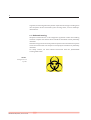
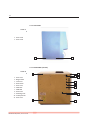
1.7 Biohazard warning
Analytical instruments for in vitro diagnostic application involve the handling
of human samples and controls which should be considered at least potentially
infectious.
Therefore every part and accessory of the respective instrument which may have
come into contact with such samples must equally be considered as potentially
infectious.
For safety reasons, we have labeled instruments with the „BIOHAZARD“
warning label below.
FIGURE 1
Biological Hazard
Symbol
HumaCount 30TS / 60TS | Service manual
SAFETY INSTRUCTIONS
Notes:
9
10
HumaCount 30TS / 60TS | Service manual
INTRODUCTION
11
2 INTRODUCTION
Since HumaCount 30TS and HumaCount 60TS have so much common
characteristics, we issue a common Service Manual covering both instruments.
Information herein applies for all instruments unless otherwise noted.
To be well up in the instruments, please read this manual carefully to have the
knowledge for servicing the instruments perfectly and avoid extra costs and
wasting precious time.
In this manual, we are using the following conventions:
HC30TS – stands for HumaCount 30TS
HC60TS – stands for HumaCount 60TS
This HumaCount 30TS / HumaCount 60TS Service Manual contains the functional
descriptions of all analyzers, operation of the fluidic systems, adjustments and
settings, and very important information for the service personnel about the
service operations and possible problems.
2.1 Name and serial number
Name:
HumaCount 30TS / HumaCount 60TS Hematology Analyzer
Serial No.:
Every instrument has its own serial number, which is printed
on the rear panel label and it can be read out from Device Information or from the self test submenu. This identity number
is write-protected by HUMAN.
2.2 Integrated software
The integrated software controls the instrument operations, displays, stores,
recalls data, and allows the user to perform QC and calibration procedures and
modify the user settings. The software version number can be read out from the
Device Information or from the Self test submenu.
Every HC30TS / HC60TS software version is upgradeable (using an USB flash
drive) by the latest program developed by HUMAN, and it can be downloaded
from: http://www.human.de
12
HumaCount 30TS / 60TS | Service manual
FUNCTIONAL DESCRIPTION
13
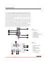
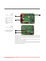
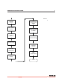
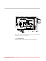
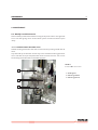
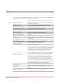
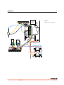
3 FUNCTIONAL DESCRIPTION
3.1 Main electronic parts of the analyzers
HC30TS / HC60TS contain the following electronic parts:
1. Counting chamber (2 pcs in HC60TS) with electrodes and measuring aperture
2. HGB Measuring Head
3. Cell Counter Amplifier Board
4. MAIN CPU Board with Dimm-PC and measurement processing unit, 4 motor controllers, valve & pneumatic
controller/driver, pump driver and power supply for internal printer (+7.5V) and digital circuitry (+5V, +3.3V)
5. DIMM-PC module
6. Motors with opto-boards of needle moving motor (H) and sample rotor/needle moving motor (V)
7. Dilutor block with opto-board for sampling, diluent, lyse and cleaner
8. Valve boards (set of 5 and max. 7)
9. Peristaltic Pump (2 pcs in HC60TS)
10. USB interface
11. Graphic LCD Display Module with touch-screen
12. Start Button Panel
13. Internal Printer
HumaCount 30TS / 60TS | Service manual
External PC
USB stick
External keyboard
ACS Main Board v2.1
USB B
USB A 4
USB A 3
USB A 2
USB A 1
Digital power 3.3V
Digital power 5V
USB
HUB
DIMMPC
AMD Elan SC-520
FPGA
XCS30XL
PIC24
ȝController
LCD driver
Start Button, Status
LEDs interface
Touchscreen
interface
LCD backlight driver
To PIC ADC
DC/DC ±12V
HVB(50V, 150V)
Measure control
DIGIO
Pressure sensor
Pump driver
Valve drivers
Opto sensor interface
Motor driver 4 (used
in HC60TS only)
Start
button &
Status
LED board
Pump
Valve block I _II
Snap in optosensors
Dilutor motor( 2 in
HC60TS)
Motor driver 2
BLTS v1.0
Sign Collection Board
320*240 (QVGA)
TFT modul
w/ touchscreen
w/ LED backlight
Display
Assembly
RBC chamber
(in HC60TS only)
HGB measuring head
Counting chamber
(MIX/WBC in
HC60TS)
Fluidic System
Amplifier Board
AJ-Meas v3.1
(HC30TS)
AJ5-Meas v1.0
(HC60TS)
HGB interface
Cell counter Amplifier
Block diagram
Motor driver 3
Rotor motor
Motor driver 1
Motor driver 1
MAIN Board (CPU, Pneumatic and Power Board)
FIGURE 2
External printer
12 VDC
external Power
Supply
Internal printer
interface
14
FUNCTIONAL DESCRIPTION
15
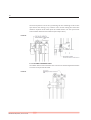
3.1.1 COUNTING CHAMBER WITH ELECTRODES AND MEASURING APERTURE
Impedance method is used for determination of volume and number of cells.
In this method a known volume of dilution is drawn through a small aperture.
Constant current is passed through the aperture from one side to the other.
When a cell passes through the aperture, it causes a change in resistance, which
generates a voltage pulse.
The amplitude of the voltage pulse is proportional to the ratio of cell volume
per aperture volume. This is used to determine the volume of cells. The number
of cells can be obtained by counting the pulses. In the HC30TS there is one
cell-counter probe: the aperture size is 70 μm and has a reference electrode
assembly and U-shaped metal fixing as it is shown in the figure below.
The aperture is made of ruby and it is molded into the end of the measuring tube.
In the HC60TS there are two separate chambers: one for counting RBC with an
aperture of 80 μm, and another for MIX/WBC/HGB with 100 μm aperture.
4
FIGURE 3
1
Measuring chamber
2
1 Washing inlet
2 Counting chamber
3
5
6
3 Opening for measuring tube
4 Chamber extender
5 Platinum electrode
6 Draining connection
1
FIGURE 4
Measuring tube
6
5
1 Complete measuring tube
2 O-rings
3 Reference electrode
4 U-shaped metal fixing
4
5 Aperture
6 Measuring tube with aperture (70/80/100μm)
2
2
3
16
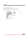
3.1.2 HGB MEASURING HEAD
Hemoglobin head is placed around one measuring chamber in all instruments.
It contains: light source (LED) at 540 nm wavelength and Photo
Detector (TSL235). The Photo Detector converts the light to frequency. The HGB
concentration is a logarithmic function of this frequency measured by the
FPGA circuit of the MAIN board.
2
FIGURE 5
HGB measuring head
1 LED
1
3
2 Connection to
the amplifier
3 TSL 235
!
Due to enhanced HGB technology, HC30TS / HC60TS is
less sensitive to incident light
changes. However, it is recommended to keep side door closed
during measurements.
The analyzer performs enhanced hemoglobin measurement technology for HGB
measurement. The frequency output signal of TSL235 is counted by a digital
counter in the FPGA circuit.
This counter counts up while the LED is on and counts down while the LED
is off. The LED and direction of counting are switched with a 100 Hz signal.
This method provides “real time backlight correction”, which makes the HGB
measurement more precise in changing backlight environment situation as well.
There are two kinds of HGB measurement:
- Sample measurement (before RBC counting)
- Diluent/blank measurement (in WBC washing phase)
The HGB result is calculated from these measurements by:
HGB log (CNTdiluent light / CNTsample light)
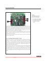
3.1.3 CELL COUNTER AMPLIFIER BOARD – HC30TS
Amplifier board includes its own voltage regulator, connection interfaces to
HGB head and to MAIN board. There is a current generator circuit on it, which
works from 50V measuring voltage (generated by MAIN) and the probe voltage
(DC) is amplified with a voltage follower (output: ELV). Nominal measuring
current is 870 μA.
Amplifier board includes one input connector for the chamber (measuring
electrode). There are two opto switches (U1, U3) to connect high voltage to the
probe with HSW signal and isolate the input of the amplifier. Test circuit makes
possible to generate test pulses (with TEST and PLS signals through FETs) for
checking the proper operation of the amplifier channel.
HumaCount 30TS / 60TS | Service manual
FUNCTIONAL DESCRIPTION
17
FIGURE 6
Cell counter amplifier board
2
3
1
1 Connection to HVB on Main
2 Connection to CSA1 on Main
3 Connection to DIGIO on
Main
Amplifier board includes a 3-stage main amplifier channel, which gains input
signal to the 0...3.3 V range (this is the input range of the A/D converter, which
is placed on the MAIN board). The RSW signal changes the gain (RBC, WBC) in
the feedback of the second amplifier stage with U2 (MAX319) analog switch.
Amplifier gain and offset are adjusted by software.
DHON signal switches on the LED and the MVON signal – which is active during
counting – switches off the Photo Detector in the HGB head, to prevent noise
generated by the HGB detector.
The other side of the amplifier board contains special connectors for the chamber and the HGB head (JP4).
3.1.4 CELL COUNTER AMPLIFIER BOARD – HC60TS
Amplifier board includes its own voltage regulators, connection interfaces to
HGB head, to chamber electrodes, high voltage and DIGIO connector to Main
board. There is a current generator circuit on this board, which works from
50V measuring voltage (generated by the High Voltage Circuit on Main board)
and the probe voltage (DC) is amplified with a voltage follower (output: ELV).
Nominal measuring current is 870 μA.
Amplifier board includes one input connector for each measuring chamber
(measuring electrodes). There is one opto switch (OPT1) and a relay (REL1) to
connect high voltage to one of the probes with HSW signal and to isolate the
input of the amplifier. Test circuit allows generating test pulses (with TEST and
PLS signals through Q1, Q2 FETs) for checking proper operation of each amplifier
channel.
18
FIGURE 7
3
Cell counter amplifier board front side
1
1 Connection to Main board,
HVB
2 Connection to Main board,
2
DIGIO
3 Connection to Main board,
amplifier in
FIGURE 8
Cell counter amplifier board back side
1 Connection to the electrodes
1
2 Connection to HGB head
2
Amplifier board includes a 3-stage main amplifier channel, which gains input
signal to the 0...3.3 V range (this is the input range of the A/D converter on the
Main board). The RSW signal (with Q8 transistor) changes the input electrode
through REL2 relay.
The bottom side of the amplifier board contains special connectors for the
electrodes and the HGB head (JP2).
DHON signal - from the MAIN board - switches on (with Q4) the LED and the
PLS signal switches off the Photo Detector in the HGB head, to prevent noise
generated by the HGB detector.
HumaCount 30TS / 60TS | Service manual
FUNCTIONAL DESCRIPTION
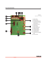
3.1.5 MAIN CPU BOARD
This board contains:
- DIMM-PC and measurement processing unit,
- 4 motor controllers,
- valve & pneumatic controller/drivers, pump driver(s)
- power supply for internal printer (+7.5V) and digital circuitry (+5V, +3.3V)
MAIN board is responsible to control the instrument: contains the main power
regulator circuits, valve and motor driver circuits and other connections for the
fluidic and pneumatic system’s parts, responsible for the specific measurement
processing functions.
The central micro-controller with a FPGA and with several other digital chips
(buffers, decoder, multiplexer) handles the pneumatic system, displaying,
measurement and data management.
Power system: filtering the +12V Input and generates +3.3V (FPGA), +5V (Digital
power), +7.5V (Printer power). Filtered +12V is used for the power of motors and
valves.
Motor drivers: 4 power drivers; Horizontal, Vertical/Sample rotor motors and
dilutor motors (2 in HC60TS) have separated ribbon cable connections.
Valve driver: consists two 8-bit, powered output shift registers (with built in
protection diodes) and there is one common ribbon cable connection for the
valve boards. The peristaltic pump has a separated power FET driver circuit for
more reliable operation.
Measurement processing: the A/D conversion made by the microcontroller itself, but several preprocessing steps (time limits, noise handling,
pulse integration) taken by the external analog circuitry.
19
20
15
FIGURE 9
14
1
Main board - front view
2
13
1 Power Supply
for internal printer 7.5 VDC
2 Opto detectors` shift regi-
3
12
ster
3 USB HUB
4 DIMMPC
5 RS232/USB Converter
4
5
11
6 Speaker
7 FPGA
8 Power Supply 12VDC>5VDC, 3.3VDC
6
7
10
9 High Voltage Circuit 12VDC
-> ±12VDC, 50VDC for
measurement, 150VDC for
cleaning
8
10 Microcontroller
11 TFT connection
12 TFT backlight driver
13 Motor drivers
14 Valve drivers
15 Pump drivers
HumaCount 30TS / 60TS | Service manual
9
FUNCTIONAL DESCRIPTION
21
14
13
12
11
FIGURE 10
Main board - rear view
1
2
1 Pressure Sensor
3
10
2 Motor Connectors
3 Front Panel USB Connector
4 Connector to TFT, Backlight
and Start Button
4
5 Connectors to Amplifiers
6 Internal battery
9
7 Power Connector
8 Power Switch Connector
9 USB B Type Interface
8
10 USB A Type Interfaces
11 Connectors to Optos
5
12 Pump Connector #1
7
13 Pump Connector #2 (HC60TS
Only)
6
14 Valves Connector
22
3.1.6 DIMM-PC* MODULE
The MAIN board incorporates a credit-card sized PC, named Dimm-PC*. The
processor on the Dimm-PC is a 133MHz Pentium-class core, with 32Mbytes
on-board RAM, and 32Mbytes on-board flash. This is the SSD (Solid State Disk)
of the analyzer, so instrument software with all user settings, calibration, database, etc. is stored on the Dimm-PC.
* DimmPC® is the Trade Mark of Kontron Embedded Modules GmbH
FIGURE 11
DIMM-PC
1
10
1 Flash BIOS
2
2 32 Mbytes RAM
9
3 CMOS EEPROM
4 On-board SMPS
5 Edge connector
3
8
6 AMD Elan SC520 CPU
7 Super I/O
8 Realtime clock
4
7
9 SSD controller
10 SSD
5
6
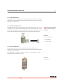
3.1.7 OPTO SENSORS
Opto sensor snap-in modules are responsible for checking motor positions.
There are 6 opto sensors in HC60TS, and 5 in HC30TS (see cabling diagram).
FIGURE 12
Opto sensor
HumaCount 30TS / 60TS | Service manual
FUNCTIONAL DESCRIPTION
23
3.1.8 VALVE BOARDS
There are two kinds of valve boards: Valve board 1-5 and Valve board 6-12.
FIGURE 13
Valve assembly
1
1 Valves
2 Valve Board
3 Connection to Main board
2
3
HC30TS has 5 valves, while HC60TS has 6 valves in Valve board 6-12 module.
The valve boards are connected to controller and driver chips which are located
on the MAIN board.
3.1.9 TFT DISPLAY AND START BUTTON BOARD
FIGURE 14
Front panel connections
1 Touchscreen connector
4
2 Start button & status LED
connector
3 Ribbon cable from TFT/
Touch board to Main board
4 TFT connector to Main board
5 TFT Backlight connector
1
2
3
5
6
6 Ribbon cable from TFT/
Touch board to Main board
24
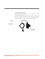
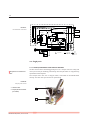
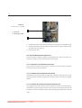
3.1.10 EXTERNAL POWER SUPPLY
The analyzer works with an external power supply. The figure below shows the
power supply unit generating 12VDC.
The power supply modules have an auto range input, which makes possible
to use them with 230V or 115V mains outlet and it has the CE and UL safety
certificate. The input socket of the power supply is a standard 3-terminal plug,
with power cable connection; the output is a coaxial power connector.
FIGURE 15
Power supply
1 230 AC inlet
2 12V DC outlet
HumaCount 30TS / 60TS | Service manual
MAIN MECHANIC AND FLUIDIC PARTS
25
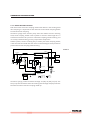
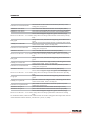
4 MAIN MECHANIC AND FLUIDIC PARTS
HC30TS and HC60TS Hematology Analyzers consist of the following mechanic
and fluidic parts:
1. Sample rotor
2. Sampling needle
3. Washing head
4. Sample/Horizontal moving unit
5. Micro Dilutor
6. Dilutor
7. Chamber
8. Cell-counter probe
9. Puffer reservoir
10. Pump
11. Valves
12. Tubing
FIGURE 16 :
3
2
1
2
1
V2 DilWash
V4 DilNeedle
1
3
V3 DilChamber
HC 30TS fluidic schematic
2
3
DILUENT
V5 LyseWbc
1
2
2
3
Pressure
Meter
1
V1 Cleaner
3
P
V9 DilAperture
1
2
CLEANER
Lyse
3
Macro
V8 Bubble
2
Micro dilutor
RBC
WBC
1
Puffer
Reservoir
Dil M3
HGB
2
LYSE
V7 DrainAperture
1
M2
Ver
2
V6 DrainChamber
1
1
2
3
V10 DrainPuffer
M1
Pump
2
M1
WASTE
Stepper Motor
1
2-way Valve
Closed = Off
Open = On
1
2
3
3-way
Valve
1-3 = Off
2-3 = On
Sample/
H motor
26
V2 DilNeedle
V1 DilWash
1
1
2
3
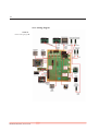
FIGURE 17
2
3
1
HC 60TS fluidic schematic
3
V4 DilChamber
2
P
2
V5 LyseWBC
1
3
2
1
3
Diluent
1
V10
2
3
1
Diluent
DILUENT
V3 Cleaner
Puffer
Reservoir
CLEANER
2
V7 Aperture
Lyse
1
3
RBC
2
V9
Bubble
MIX
WBC
Diluent
Micro dilutor
HGB
M3
M4
M2
LYSE
2
2
Ver
V8 Drainchamber
V6 DrainChamber
2
1
1
3
1
V11 DrainPuffer
Sample/
H motor
M1
Pump 1
Pump 2
2
M1
WASTE
Stepper Motor
1
2-way Valve
Closed = Off
Open = On
1
2
3
3-way
Valve
1-3 = Off
2-3 = On
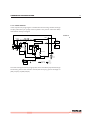
4.1 Single parts
!
Sample rotor is maintenancefree.
4.1.1 SAMPLE/HORIZONTAL AND VERTICAL MOTORS
HC30TS and HC60TS Hematology Analyzers has a sample rotor for safety and
more precise sample handling. Commonly used sample tubes are supported by
replaceable tube adapters.
The Sample rotor unit uses a stepper motor, connected to the MAIN board
directly. The rotor has opto sensors for positioning.
FIGURE 18
Sample probe motors
1 Vertical motor
1
2 Sample/Horizontal motor
(not visible)
2
HumaCount 30TS / 60TS | Service manual
MAIN MECHANIC AND FLUIDIC PARTS
27
4.1.2 SAMPLING NEEDLE
Sampling needle is assembled in the H&V moving unit and it makes the sample
aspirations. Correct setting of sampling needle is necessary and very important
(see Chapter Adjustments).
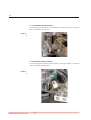
4.1.3 NEEDLE WASHING HEAD
Washing head is located at the bottom of the H&V moving unit and it is for
cleaning the outer surface of the sampling needle. This washing process is made
with diluent reagent and the fluid is drained by the pump. The arrows on the
picture show the direction of diluent flow during sampling needle washing.
!
Clean or replace washing head
yearly, or after 10 000 mea-
surements.
FIGURE 19
Needle washing head
1
1 Clean diluent
2
2 Pump to waste
4.1.4 PUFFER RESERVOIR
The glass puffer reservoir is directly connected to the pressure sensor.
During measurement, there is no pump activity, so the puffer reservoir maintains
measuring vacuum stable.
The instrument measures relative pressure so measuring vacuum is
independent of atmospheric pressure.
FIGURE 20
Puffer reservoir
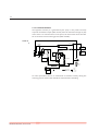
28
4.1.5 DILUTOR BLOCK – HC30TS
FIGURE 21
4
1 Micro dilutor
1
2 Positioners
3 Positioners
5
6
4 Pistons
5 Pistons
6 Diluent syringe
7 Lyse syringe
2
3
!
Maintenance should be provided to the piston tips, by
applying neutral silicon grease
to the cogged end of the Macro
and Lyse pistons, between the
syringe and the tip itself. This
will ensure optimum sealing and
longer lifetime of piston tips.
Greasing of the cogged transmission
parts
(cogwheel
and
cogged bar) should be done
regularly using machine grease.
It is recommended to check and
repeat greasing of piston tips,
and transmission gear every year,
or after 10000 measurements.
HumaCount 30TS / 60TS | Service manual
In HC30TS this unit includes one dilutor stepper motor. The Micro dilutor
syringe makes the aspirating while the motor moves down. The syringes are
mechanically connected with a loose mechanism, so there is a phase along the
track, where the micro dilutor doesn’t move.
MAIN MECHANIC AND FLUIDIC PARTS
29
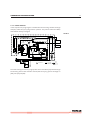
4.1.6 DILUTOR BLOCK – HC60TS
FIGURE 22
1 Micro dilutor
2 Diluent 1 syringe
3 Positioners
4 Positioners
5 Lyse syringe
6 Diluent 2 syringes
1
5
2
6
3
4
In HC60TS this unit includes two dilutor channels – one for diluent and sampling,
and another one for lyse and diluent reagents. There are two stepper motors,
4 opto sensors, five syringes and piston rods with gear transmission. The Micro
dilutor syringe makes the aspirating while the motor moves down. The syringes
are mechanically connected with a loose mechanism, so there is a phase along
the track, where the micro dilutor doesn’t move.
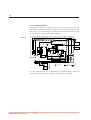
30
4.1.7 MEASURING BLOCK (HC30TS)
The measuring block contains all components, counting chamber, measuring
tubes, HGB head, draining tubes.
FIGURE 23
4.1.8 MEASURING BLOCK (HC60TS)
The measuring block contains all components, counting chambers, measuring
tubes, HGB head, draining tubes.
FIGURE 24
HumaCount 30TS / 60TS | Service manual
MAIN MECHANIC AND FLUIDIC PARTS
31
4.1.9 PUMP
Pump generates regulated vacuum and drains the fluidic system. It is connected
to the MAIN board and it has its own driver circuit (Power FET). In HC60TS there
are two pumps.
The pump is maintenance free.
FIGURE 25
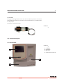
4.2 Assembled Analyzer
4.2.1 FRONT PANEL
FIGURE 26
1 TFT display
1
2 Start button
3 USB socket
4 Sample holder/Sample rotor
2
4
3
32
4.2.2 SIDE PANEL
FIGURE 27
1 Cover screws
2 Cover screws
1
2
4.2.3 REAR PANEL (HC30TS)
FIGURE 28
1
3
4
5
1 Cover screw
2 Reagent inlets
3 cover screw
6
4 Power switch
7
5 Cover screw
8
6 USB A inlet
7 USB B inlet
8 Cover Screw
9
10
9 Grounding screw
10 12 VDC power IN
11 Cover screw
2
HumaCount 30TS / 60TS | Service manual
11
MAIN MECHANIC AND FLUIDIC PARTS
33
4.2.4 CONSTRUCTION FRONT
6
FIGURE 29
1 Main board
1
2 Pump II (only in HC60TS)
7
3 Vertical motor
4 Pump I
2
5 Amplifier box
6 Valves
7 Dilutor motor
3
8 Valves
9 Sample/Horizontal motor
8
4
5
9
4.2.5 CONSTRUCTION SIDE
FIGURE 30
1
1 Valves 1-5
6
2 Micro dilutor
3 Dilutor 1
2
7
4 RBC Chamber
3
8
5 MIX/WBC Chamber (only in
HC60TS)
6 Puffer reservoir
4
7 Lyse syrenge
5
8 Dilutor 2
9 Valves 6-10 (6-11 in HC60TS)
9
34
FIGURE 31
Construction side of
HC30TS
1 MAIN board
1
2 Dimm-PC
2
FIGURE 32
Construction side of
HC60TS
1
1 MAIN board
2 Dimm-PC
HumaCount 30TS / 60TS | Service manual
2
OPERATION OF THE FLUIDIC SYSTEM
5 OPERATION OF THE FLUIDIC SYSTEM
This section describes the main fluidic steps of HC30TS / HC60 TS
measurement cycle. The instrument’s Fluidic Schematics are shown in Section 10.4
of this manual. The following figures show total measurement flow diagram and
detailed descriptions of processes for understanding the fluidic system work.
The following steps are introduced in this section:
1.
2.
3.
4.
5.
6.
7.
8.
9.
Flow diagram of measurement
Initialization process
Sampling process
Needle washing process
Diluting process
Lysing process
Counting process
Chamber draining process
Shutdown process
In the detailed process description figures, the active tube is filled with black
color, while an arrow shows the direction of the flow. Moving mechanic parts
have another arrow indicating direction of movement. Only opened (On) valves
are mentioned in this section while all the other valves are closed (Off).
HC30TS / HC60TS employs software counters to estimate waste (and other reagent) level. Software integrates volume of the reagents used, and gives a message when this volume reaches the preset tank capacity.
5.1 Initialization of the Fluidic System
Fluidic initialization process performs the following steps:
- Checking of pump and pressure sensor by generating measuring vacuum
- Positioning all mechanical components by scanning moving range (with
end-switches)
- Priming of reagents
- Cleaning of tubing & measuring chamber
- Cleaning of aperture with high-pressure back-flush, cleaner reagent & highvoltage burning
35
36
5.2 Operation of the fluidic system in HUMACOUNT 30 TS
5.2.1 FLOW DIAGRAM OF MEASUREMENT
FIGURE 33
Chamber draining
Fill up with 1ml
diluent for WBC
dilution
Sampling process
Needle washing
Diluting process
(1:160)
Sampling process
(from primary
dilution)
Needle washing
Lysing process
HumaCount 30TS / 60TS | Service manual
OPERATION OF THE FLUIDIC SYSTEM
37
FIGURE 34
Generating
measuring
vacuum
WBC counting
process
Fill up with 1ml
diluent for RBC
dilution
Dilution process
(1:25600)
HGB
measurement
Needle washing
Extensive cleaning
Generating
measuring
vacuum
Blank HGB
measurement
RBC
measurement
Draining
END
38
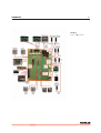
5.2.2 SAMPLING PROCESS
The aspirating needle aspirates 25 μL (50 μL in prediluted mode) of blood sample. The Micro dilutor syringe makes the aspirating while the M3 Micro-dilutor
motor moves down. The syringes are mechanically connected with a loose mechanism, so there is a phase along the track, where the micro dilutor doesn’t
move.
FIGURE 35
3
2
1
1
2
1
V2 DilWash
V4 DilNeedle
3
V3 DilChamber
2
3
DILUENT
V5 LyseWbc
1
2
2
3
Pressure
Meter
1
V1 Cleaner
3
P
V9 DilAperture
2
1
CLEANER
Lyse
3
Macro
V8 Bubble
2
Micro dilutor
RBC
WBC
1
Puffer
Reservoir
Dil M3
HGB
2
LYSE
V7 DrainAperture
1
M2
Ver
2
V6 DrainChamber
1
1
2
3
V10 DrainPuffer
M1
Sample/
H motor
Pump
2
M1
WASTE
Stepper Motor
1
2-way Valve
Closed = Off
Open = On
1
2
3
3-way
Valve
1-3 = Off
2-3 = On
There is also another sampling process for the second (RBC) dilution, 25 μL of
primary dilution is aspirated by the sampling needle from the chamber but it
is kept in the sampling needle during the WBC measurement and the cleaning
process.
HumaCount 30TS / 60TS | Service manual
OPERATION OF THE FLUIDIC SYSTEM
39
5.2.3 NEEDLE WASHING PROCESS
Both instruments clean the sampling needle with diluent in the washing head
after sampling. It is important to clean the outer surface of the sampling needle
to avoid inaccurate sampling.
The Macro syringe doses and the pump drains the diluent from the washing
head, while sampling needle moves upwards so that the total length of it is
washed and cleaned. This process is called total sampling needle washing, and
it is mainly used after taking primary sample from sample tube.
Another process, which is washing only a smaller part of the sampling needle,
is the same but the needle does not move in the total length. Some procedures
perform this kind of sampling needle washing.
FIGURE 36
3
2
1
2
1
V2 DilWash
V4 DilNeedle
1
3
V3 DilChamber
2
3
DILUENT
V5 LyseWbc
1
2
2
3
Pressure
Meter P
1
V1 Cleaner
3
V9 DilAperture
1
2
CLEANER
Lyse
3
Macro
V8 Bubble
2
Micro dilutor
RBC
WBC
1
Puffer
Reservoir
Dil M3
HGB
2
LYSE
V7 DrainAperture
1
M2
Ver
2
V6 DrainChamber
1
1
2
3
V10 DrainPuffer
M1
Sample/
H motor
Pump
2
M1
WASTE
Stepper Motor
1
2-way Valve
Closed = Off
Open = On
1
2
3
3-way
Valve
1-3 = Off
2-3 = On
The Macro syringe pushes the diluent through V4 (Off), V3 (Off), V2 (On). The
Pump aspirates the diluent from the washing head through V10(On), while the
M2 Vertical motor moves the sampling needle up.
40
5.2.4 DILUTING PROCESS
The parts of the fluidics are rinsed with diluent reagent. The measuring chamber
is filled up with 1 ml of diluent. This method prevents the chamber from dirt and
makes the diluting process faster.
The sampling process has aspirated 25 μL of sample, which is in the sampling
needle. In the first diluting step the sample is dispensed into the measuring
chamber with 3 ml of diluent, which comes from the Macro syringe through V4
(On) and Micro-dilutor, while the M3 Dilutor motor moves upwards. This
process makes the 1:160 first dilution rate in the chamber.
FIGURE 37
3
2
1
1
2
1
V2 DilWash
V4 DilNeedle
3
V3 DilChamber
2
3
DILUENT
V5 LyseWbc
1
2
2
3
Pressure
Meter
1
V1 Cleaner
3
P
V9 DilAperture
2
1
CLEANER
Macro
RBC
WBC
1
Puffer
Reservoir
Lyse
3
V8 Bubble
Dil M3
2
Micro dilutor
HGB
2
LYSE
V7 DrainAperture
1
M2
Ver
2
V6 DrainChamber
1
2
1
3
V10 DrainPuffer
M1
Sample/
H motor
Pump
2
M1
WASTE
Stepper Motor
1
2-way Valve
Closed = Off
Open = On
1
2
3
3-way
Valve
1-3 = Off
2-3 = On
The second sample – 25 μL of primary dilution – is stored in the sampling needle
during the WBC measurement and the cleaning process. The instrument makes
the second (RBC) dilution into the chamber after these processes.
HumaCount 30TS / 60TS | Service manual
OPERATION OF THE FLUIDIC SYSTEM
41
5.2.5 LYSING PROCESS
In this step the set lysing reagent is added into the measuring chamber through
V5 (On), while the Lyse syringe moves upwards. This process makes the WBC/
HGB dilution with lyse reagent.
FIGURE 38
3
1
2
1
2
1
V2 DilWash
V4 DilNeedle
3
V3 DilChamber
2
3
DILUENT
V5 LyseWbc
1
2
2
3
Pressure
Meter P
1
V1 Cleaner
3
V9 DilAperture
1
2
CLEANER
Lyse
3
Macro
V8 Bubble
2
Micro dilutor
RBC
WBC
1
Puffer
Reservoir
Dil M3
HGB
2
LYSE
V7 DrainAperture
1
M2
Ver
2
V6 DrainChamber
1
1
2
3
V10 DrainPuffer
M1
Sample/
H motor
Pump
2
M1
WASTE
Stepper Motor
1
2-way Valve
Closed = Off
Open = On
1
2
3
3-way
Valve
1-3 = Off
2-3 = On
For better mixing the macro syringe pushes some air bubbles (aspirated through
the washing inlet of the chamber and V8) after the lysing process through V4
(Off), V3 (On), V9 (Off) V8 (On).
42
5.2.6 COUNTING PROCESS
The regulated vacuum (it is generated by the pump in the puffer reservoir)
aspirates the diluted sample (WBC or RBC) from the chamber through V7 (On)
valve. There is no volume limiter in the system, the instrument counts the cells
for 8.5 seconds in both counting phases (WBC and RBC).
FIGURE 39
3
1
2
1
2
1
V2 DilWash
V4 DilNeedle
3
V3 DilChamber
2
3
DILUENT
V5 LyseWbc
1
2
2
3
Pressure
Meter P
1
V1 Cleaner
3
V9 DilAperture
1
2
CLEANER
Lyse
3
Macro
V8 Bubble
2
Micro dilutor
RBC
WBC
1
Puffer
Reservoir
Dil M3
HGB
2
LYSE
V7 DrainAperture
1
M2
Ver
2
V6 DrainChamber
1
1
2
3
V10 DrainPuffer
M1
Sample/
H motor
Pump
2
M1
WASTE
Stepper Motor
1
2-way Valve
Closed = Off
Open = On
1
2
3
3-way
Valve
1-3 = Off
2-3 = On
For noise prevention there is no mechanical or electronic activity during the
counting process and the door should be closed for better shielding.
HumaCount 30TS / 60TS | Service manual
OPERATION OF THE FLUIDIC SYSTEM
43
5.2.7 CHAMBER DRAINING PROCESS
Chamber draining is made under pressure control. Pump drains chamber while
puffer reservoir and thus the pressure sensor is connected to the draining tube.
The instrument can detect the empty state of the chamber from drop of vacuum
.
FIGURE 40
3
1
2
1
2
1
V2 DilWash
V4 DilNeedle
3
V3 DilChamber
2
3
DILUENT
V5 LyseWbc
1
2
2
3
Pressure
Meter P
1
V1 Cleaner
3
V9 DilAperture
1
2
CLEANER
Lyse
3
Macro
V8 Bubble
2
Micro dilutor
RBC
WBC
1
Puffer
Reservoir
Dil M3
HGB
2
LYSE
V7 DrainAperture
1
M2
Ver
2
V6 DrainChamber
1
1
2
3
V10 DrainPuffer
M1
Sample/
H motor
Pump
2
M1
WASTE
Stepper Motor
1
2-way Valve
Closed = Off
Open = On
1
2
3
3-way
Valve
1-3 = Off
2-3 = On
5.2.8 SHUTDOWN PROCESS
The fluidic shutdown performs the following steps:
- Priming chamber with reagent to avoid drying out of aperture
- Sampling needle is positioned above counting chamber, needle up
- Lyse syringe are positioned up
- Diluent syringes are positioned up
- Sample rotor moved out
44
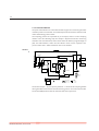
5.3 Operation of the fluidic system in HC60TS
The HC60TS fluidic system operates in two parallel pneumatic processes. The
first subsystem consists of the following components: Microdilutor, Diluent I.
dilutor, V1 valve, washing head, Pump 2. This subsystem is marked with a
dotted line outline in the charts. The second subsystem consists of the
remaining fluidic components. Thanks to this two parallel subsystems the
measuring is could be started during the chamber washing processes. The
separate RBC and MIX/WBC chambers make two different diluents mixes
possible simultaneously.
FIGURE 41
RBC chamber
Flow diagram of
Both chambers
MIX/WBC
chamber
Needle
subsystem
Sampling process
Cleaning
chambers
measurement
HGB Blank
measurement
Chamber draining
Needle washing
Diluting process
(1:160)
Diluting process
(1:160)
Sampling process
(from primary
dilution)
Lysing process
Dilution process
(1:23000)
Dilution process
(1:23000)
Generating
measuring
vacuum
WBC counting
process, HGB
measurement
RBC counting
process
Draining
Cleaning
Fast Blank
measurement
END
HumaCount 30TS / 60TS | Service manual
Needle washing
OPERATION OF THE FLUIDIC SYSTEM
45
5.3.1 SAMPLING PROCESS
The aspirating needle aspirates 25 μL (50 μL in prediluted mode) of blood sample. The Micro dilutor syringe makes the aspirating while the M3 Micro-dilutor
motor moves down. The syringes are mechanically connected with a loose mechanism, so there is a phase along the track, where the micro dilutor doesn’t
move.
FIGURE 42
V2 DilNeedle
1
V1 DilWash
1
2
3
2
3
1
3
V4 DilChamber
2
P
1
2
3
2
1
3
Diluent
1
V10
2
3
CLEANER
2
1
Diluent
DILUENT
V3 Cleaner
Puffer
Reservoir
V5 LyseWBC
V7 Aperture
Lyse
1
3
RBC
2
V9
Bubble
MIX
WBC
Diluent
Micro dilutor
HGB
M3
M4
M2
LYSE
2
2
Ver
V8 Drainchamber
V6 DrainChamber
2
1
1
3
1
V11 DrainPuffer
Sample/
H motor
M1
Pump 1
Pump 2
2
M1
WASTE
Stepper Motor
1
2-way Valve
Closed = Off
Open = On
1
2
3
3-way
Valve
1-3 = Off
2-3 = On
The second sample – 35 μL of primary dilution – is made in the RBC chamber.
The instrument makes the second (RBC) dilution into the chamber after straight
after the WBC dilution.
46
5.3.2 DILUTING PROCESS
The parts of the fluidics are rinsed with diluent reagent. The measuring chamber
is filled up with 1 ml of diluent. This method prevents the chamber from dirt and
makes the diluting process faster.
The sampling process has aspirated 25 μL of sample, which is in the sampling
needle. In the first diluting step the sample is dispensed into the measuring
chamber with 3 ml of diluent, which comes from the Diluent I. syringe through
V2 (On) and Micro-dilutor, while the M3 Dilutor motor moves upwards. This process makes the 1:160 first dilution rate in the chamber.
FIGURE 43
V2 DilNeedle
1
V1 DilWash
1
2
3
2
3
1
3
V4 DilChamber
2
P
2
V5 LyseWBC
1
3
2
1
3
Diluent
1
V10
2
3
CLEANER
2
1
Diluent
DILUENT
V3 Cleaner
Puffer
Reservoir
V7 Aperture
Lyse
1
3
RBC
2
V9
Bubble
MIX
WBC
Diluent
Micro dilutor
HGB
M3
M4
M2
LYSE
2
2
Ver
V8 Drainchamber
V6 DrainChamber
2
1
1
3
1
V11 DrainPuffer
Sample/
H motor
M1
Pump 1
Pump 2
2
M1
WASTE
Stepper Motor
1
2-way Valve
Closed = Off
Open = On
1
2
3
3-way
Valve
1-3 = Off
2-3 = On
The second sample – 25 μL of primary dilution – is made right after the first
dilution. The second dilution is made in the RBC chamber.
HumaCount 30TS / 60TS | Service manual
OPERATION OF THE FLUIDIC SYSTEM
47
5.3.3 LYSING PROCESS
In this step the set lysing reagent is added into the measuring chamber through
V10 (On), while the Lyse syringe moves upwards. This process makes the WBC/
HGB dilution with lyse reagent.
FIGURE 44
V2 DilNeedle
1
V1 DilWash
1
2
3
2
3
1
3
V4 DilChamber
2
P
1
2
3
2
1
3
Diluent
1
V10
2
3
CLEANER
2
1
Diluent
DILUENT
V3 Cleaner
Puffer
Reservoir
V5 LyseWBC
V7 Aperture
Lyse
1
3
RBC
2
V9
Bubble
MIX
WBC
Diluent
Micro dilutor
HGB
M3
M4
M2
LYSE
2
2
Ver
V8 Drainchamber
V6 DrainChamber
2
1
1
3
1
V11 DrainPuffer
Sample/
H motor
M1
Pump 1
Pump 2
2
M1
WASTE
Stepper Motor
1
2-way Valve
Closed = Off
Open = On
1
2
3
3-way
Valve
1-3 = Off
2-3 = On
For better mixing the macro syringe pushes some air bubbles (aspirated through
the washing inlet of the chamber and V9) after the lysing process through V4
(Off), V10 (On), V9 (Off).
48
5.3.4 COUNTING PROCESS
The regulated vacuum (it is generated by the pump in the puffer reservoir)
aspirates the diluted sample (WBC or RBC) from the chamber through V11 (On)
valve. There is no volume limiter in the system, the instrument counts the cells
for 16 seconds in counting phases (WBC and RBC).
FIGURE 45
V2 DilNeedle
1
V1 DilWash
1
2
3
2
3
1
3
V4 DilChamber
2
P
2
V5 LyseWBC
1
3
2
1
3
Diluent
1
V10
2
3
CLEANER
2
1
Diluent
DILUENT
V3 Cleaner
Puffer
Reservoir
V7 Aperture
Lyse
1
3
RBC
2
V9
Bubble
MIX
WBC
Diluent
Micro dilutor
HGB
M3
M4
M2
LYSE
2
2
Ver
V8 Drainchamber
V6 DrainChamber
2
1
1
3
1
V11 DrainPuffer
Sample/
H motor
M1
Pump 1
Pump 2
2
M1
WASTE
Stepper Motor
1
2-way Valve
Closed = Off
Open = On
1
2
3
3-way
Valve
1-3 = Off
2-3 = On
For noise prevention there is no mechanical or electronic activity during the
counting process and the door should be closed for better shielding.
HumaCount 30TS / 60TS | Service manual
OPERATION OF THE FLUIDIC SYSTEM
49
5.3.5 CHAMBER DRAINING PROCESS
Chamber draining is made under pressure control. Pump drains chamber while
puffer reservoir and thus the pressure sensor is connected to the draining tube.
The instrument can detect the empty state of the chamber from drop of vacuum.
FIGURE 46
V2 DilNeedle
1
V1 DilWash
1
2
3
2
3
1
3
V4 DilChamber
2
P
1
2
3
2
1
3
Diluent
1
V10
2
3
CLEANER
2
1
Diluent
DILUENT
V3 Cleaner
Puffer
Reservoir
V5 LyseWBC
V7 Aperture
Lyse
1
3
RBC
2
V9
Bubble
MIX
WBC
Diluent
Micro dilutor
HGB
M3
M4
M2
LYSE
2
2
Ver
V8 Drainchamber
V6 DrainChamber
2
1
1
3
1
V11 DrainPuffer
Sample/
H motor
M1
Pump 1
Pump 2
2
M1
WASTE
Stepper Motor
1
2-way Valve
Closed = Off
Open = On
1
2
3
3-way
Valve
1-3 = Off
2-3 = On
50
5.3.6 CLEANING PROCESS
The pump aspirates the cleaner through the V3 (On), V10 (On), V7 (On) valves to
puffer the cleaner reagent in the tubes between V10 and V3.
FIGURE 47
V2 DilNeedle
1
V1 DilWash
1
2
3
2
3
1
3
V4 DilChamber
2
P
2
V5 LyseWBC
1
3
2
1
3
Diluent
1
V10
2
3
CLEANER
2
1
Diluent
DILUENT
V3 Cleaner
Puffer
Reservoir
V7 Aperture
Lyse
1
3
RBC
2
V9
Bubble
MIX
WBC
Diluent
Micro dilutor
HGB
M3
M4
M2
LYSE
2
2
Ver
V8 Drainchamber
V6 DrainChamber
2
1
1
3
1
V11 DrainPuffer
Sample/
H motor
M1
Pump 1
Pump 2
2
M1
Stepper Motor
1
2-way Valve
Closed = Off
Open = On
1
2
3
WASTE
3-way
Valve
1-3 = Off
2-3 = On
After that the Diluent 2 syringes pushes the cleaner reagent remaining in the
tube between V10 and V3 into the chamber.
5.3.7 SHUTDOWN PROCESS
The fluidic shutdown performs a fluidic system cleaning with cleaner.
HumaCount 30TS / 60TS | Service manual
ADJUSTMENTS
51
6 ADJUSTMENTS
The adjustments below are made in the factory. Readjustment of following
parts is necessary if some components are replaced.
6.1 Common adjustments
6.1.1 VERTICAL MOVEMENT, SETTING TIMING BELT TENSION
The timing belt tension could be set with positioning the vertical motor using
the oval holes in the mounting plate.
FIGURE 48
6.1.2 VERTICAL OPTO SENSOR AND NEEDLE SETTINGS
The vertical opto sensor should be set as follows:
FIGURE 49
1
2
1 opto sensor
2 flag
The flag (1) mounted on the vertical needle moving mechanism must run freely
between the two parts (2) of the opto-sensor.
52
The vertical position can be set by loosening the two mounting screws of the
opto sensor and moving it up or down. In the correct setting the end of the
needle is coplanar of the lower plane of needle cleaner unit. The opto sensor
state could be checked in the software (see chapter 8.2.4)
FIGURE 50
6.1.3 SETTING THE NEEDLE SHAFT
The needle shaft must be fastened. If it was loose it could be adjusted with the
set screw on top end of the shaft.
FIGURE 51
HumaCount 30TS / 60TS | Service manual
ADJUSTMENTS
53
6.1.4 SETTING THE POSITION OF THE CHAMBERS
After setting the needle position according to chapter 5.2.2 and 5.3.1. the
horizontal position of chamber bracket should be checked. The needle must not
go down exactly in the center of the chamber. Chamber bracket can be moved
left or right if necessary. (see picture).
FIGURE 52
54
6.2 HC30TS specific adjustments
6.2.1 SETTING THE DILUTOR MECHANICS
The micro-dilutor’s movement must be set by the following procedure:
1. Push the dilutor pistons up as possible.
2. Fasten the set screw of the upper fixing ring.
3. Fasten the lower fixing ring’s set screw in the position shown in picture on
the left.
FIGURE 53
6.2.2 SETTING THE HORIZONTAL MOVEMENT
The setting of the horizontal movement is correct, when the opto wheel is in the
position shown in the picture, then the aspirating needle bracket is as close to
the cantilever as possible.
FIGURE 54
HumaCount 30TS / 60TS | Service manual
ADJUSTMENTS
55
6.3 HC60TS specific adjustments
6.3.1 SETTING THE DILUTOR MECHANICS
The micro-dilutor’s movement must be set by the following procedure:
1. Push the dilutor pistons up as possible.
2. Fasten the set screw of the upper fixing ring.
3. Fasten the lower fixing ring’s set screw in the position shown in picture on
the left.
FIGURE 55
6.3.2 SETTING THE HORIZONTAL MOVEMENT
The setting of the horizontal movement is correct, when the opto wheel is in the
position shown in left picture, then the aspirating needle bracket is as close to
the cantilever as possible.
FIGURE 56
56
6.4 Service Calibration
The analyzer provides a menu for Service calibration purposes.
You can access the service calibration menu logged in as Service User:
Maintenance-->Calibration-->Service.
Factors: In result calculations the service calibration factors are used as
the user calibration factors, so they are multiplied for each parameter:
RBCDisp. = FactRBC User * FactRBC Serv. * RBCMeasured
If the user factor is near the bound (0.80 - 1.20), by setting the corresponding
service factor, the user factor can be adjusted to 1.00 using Apply user factors
button. Example: Fact RBC User = 1.19 and Fact RBC Serv = 0.96, and Fact RBC
User = 1.00 and Fact RBC Serv = 1.14 gives the same result for RBC.
Press white data field to modify calibration factor. A numeric input screen will
show up so that you can enter values.
All values must be in the 0.8…1.2 range.
Press Accept to proceed with new settings, or Cancel to keep values unchanged.
HumaCount 30TS / 60TS | Service manual
ADJUSTMENTS
History: You can check the previous calibration factors with the date of change
in a table form.
Apply user calibration factors function is used to combine user and service
calibration factors. The software will multiply the existing factors, and move
them to the Service level to set user factors to 1.00.
6.5 Setting RBC amplifier gain
If the correct MCV value cannot be obtained by calibration the
amplifier gain of RBC measurement could be increased or decreased by approx.
±10%. Please be advised that changing this value requires to recalibrate the
device to get proper results! The settings are under Settings-->Measurement->Setting-->Calibration.
57
58
6.6 Setting WBC amplifier gain
If the WBC diagram is shifted too far on left or right in WBC histogram the
amplifier gain of WBC measurement could be increased or decreased by approx.
±10%. Please be advised that changing this value requires to recalibrate the
device to get proper results!
The settings are under Settings-->Measurement-->Settings-->Calibration.
HumaCount 30TS / 60TS | Service manual
CHECKIG THE PROPER OPERATION
7 CHECKIG THE PROPER OPERATION
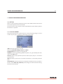
7.1 Self Test
There is a built-in Self test and Service menu in each model. Self test can be used
to check the operation of the instrument.
The test results can be printed or saved to USB flash disk. With the Retry button
the self test is repeated.
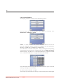
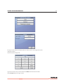
7.1.1 SELF TEST SCREENS
Every measured value has a check mark if it is in the acceptable range, or a X and
a minus or plus sign if it is below or above the normal range.
HGB measured impulses per second
Measuring Electrode voltage, current and offset.
Amplifier Noise test during a 5-second period.
Amplifier transfer by generating 20000 test pulses, incl. gain related peak value,
noise related deviation.
Vacuum reports pump operation (vacuum made by the pump in a 10-second
period of time).
Drift represents pressure loss of vacuum measured in a 10-second period of
time.
Fast blank meas, the device performs a fast blank measurement. This number is
the PLT count. Probe min, probe max probe voltage are relative numbers during
fast blank measurement.
59
60
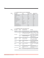
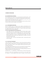
TABLE 1
7.1.2 NORMAL RANGE OF SELF TEST PARAMETERS
Parameter
Unit
Lower bound
HGB light
count
3000
Electrode voltage
V
45
Current
μA
830
Offset
mV
-5.0
Amplifier test
count
19990
Peak of test pulses
mV
1300
deviation (noise)
mV
0
Noise test
pls/5sec
0
Vacuum
mBar
300
Drift
mBar/10sec
0
Fast blank meas
count
0
Fast blank probe min
280
Fast blank probe max
280
Upper bound
60000
55
930
5.0
20050
1700
100
50
600
10
100
360
360
7.1.3 TROUBLESHOOTING GUIDE FOR SELF TEST
TABLE 2
Parameter
Mark
Possible reason
Remedy
HGB dark
HIGH
Instrument door open
Close instrument door
LOW
HGB light
HIGH
Electrode
voltage
LOW or
HIGH
Current
LOW or
HIGH
Offset
LOW or
HIGH
LOW
Amplifier test
HIGH
HumaCount 30TS / 60TS | Service manual
Check
HGB
head
HGB head not connected
connections. Check HGB
or HGB LED out of order
LED during measurement
Close door or replace
Instrument door open or
HGB LED resistor on
HGB LED too bright
amplifier board
Check measuring voltage
Fault on MAIN or
(50V) on High voltage
Amplifier board
and Amplifier boards
Check current generator,
Fault on Amplifier
and test generator FET on
board
Amplifier board
Check the offset potenFault on Amplifier
tiometer on Amplifier
board
board
Amplifier Boards is not
Check cables and
connected to main
connectors coming from
board
the Amplifier
Instrument not grounded Check mains ground lead
CHECKIG THE PROPER OPERATION
61
Check current generator,
Fault on Amplifier board and test generator FET on
Amplifier board
Instrument not
Check mains ground lead
grounded
Instrument not
Check mains ground lead
grounded
Peristaltic pump failure Check peristaltic pump
Check tubing in
Leakage in pneumatics
pneumatics
Peak of pulses
LOW or
HIGH
Dev. (noise)
HIGH
Noise
HIGH
Vacuum
LOW
Drift
HIGH
Fast Blank
meas
HIGH
Contaminated system
Fast Blank
probe min
HIGH or
LOW
Fault on MAIN or
Amplifier board
Fast Blank
probe max
HIGH or
LOW
Fault on MAIN or
Amplifier board
Run cleaning cycle
Check measuring voltage
(50V) on MAIN and Amplifier boards
Check measuring voltage
(50V) on MAIN and
Amplifier boards
7.2 Service Menu
7.2.1 ENTERING TO SERVICE MENU
There is a Service menu for servicing and operation checking purposes.
The entry point is in Maintenance --> Diagnostics --> Service
The service menu is accessible for only SERVICE user. To login as service user
please see chapter 6.2.5.
62
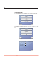
7.2.2 TROUBLESHOOTING
With Troubleshooting options provide tools to test mechanical components.
From the Motor Test submenu the service person could run each or all motor
tests.
Optosensor’s states can be checked in this screen.
HumaCount 30TS / 60TS | Service manual
CHECKIG THE PROPER OPERATION
Pressing the 0 or 1 buttons the valves could be toggled. 1 stands for
electronically forced state.
Pressing the Pump 0 or 1 button the peristaltic pump could be switched on/off.
The current vacuum in the puffer reservoir is displayed under the buttons.
You can check the offset on the amplifier board. The current offset and the
acceptance range are displayed.
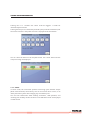
7.2.3 STRESS
In Stress mode, the instrument performs measuring cycles without sample
(blank measurements) continuously. This can be used for burn-in tests, or to
check pneumatic system after changing any main fluidic parts.
You can have information about stability, cleanliness, HGB operation, and
counting time stability. Results of the PLT and HGB blank results are displayed
in table format.
63
64
You can detect any kind of noise, or bubbles in the system if the PLT is not stable
low, or HGB has big variation. To exit from this mode press the Abort button (at
the end of a normal cycle) until the Stress operation is finished.
7.2.4 NEEDLE POSITION CHECK
The service personal can check the correct needle setting touching Needle
position check button. If the needle opto is set correctly, then after the button
touch the needle lower end is co-planar with the bottom plane of the washing
head. If it doesn’t then adjust the needle opto up or down and check the position
again.
7.2.5 LOG IN AS SERVICE USER
Certain service functions are accessible only for the SERVICE user.
In Main menu touch Exit button.
If you are logged in as different user touch Logout(USERNAME) and then the Log
In button, else touch Log In button.
HumaCount 30TS / 60TS | Service manual
CHECKIG THE PROPER OPERATION
At Log In screen Press the START button on front panel, so the Login Name will
change to Service.
Touch Password empty field.
Type in the Service User password which is 6484, then touch Enter button.
Touch Accept button on Log In screen.
65
66
HumaCount 30TS / 60TS | Service manual
SERVICE OPERATION
8 SERVICE OPERATION
8.1 Possible Causes of Noise
Generally high count of any particle - even if you think it should be low, or near
zero - can be caused by noise, i.e. something interfere with the measurement.
The most important thing in these cases is to identify the source of the noise,
otherwise you cannot protect the system against it.
Noise can come from several sources, and the different sources add up. However
only one of them may be enough to cause problems.
8.1.1 CONTAMINATED REAGENT
The most probable cause are particles in the reagent, and therefore the PLT
blank is continuously high (e.g. always 30-40). You can easily sort out this case
by replacing diluent with a new container. PLT blank must go down during
several blank measurements (below 10).
How can a good reagent become bad with time?
- If the reagent tube was contaminated, and some bacteria begin to grow
inside, once you put an infected reagent tube into a new tank, by time it
can become infected as well, i.e. the background (PLT blank) becomes high.
Wash the reagent tube - which is in connection with the reagent - with 1% of
bleach solution, then rinse with clean distilled water or diluent. It can avoid
the bacteria to grow inside.
- If container is open – and cap is not installed or closed - external dust can fall
into the reagent.
8.1.2 BAD EARTH GROUNDING
In this case external - ground referenced - noise can get into the system by
ground coupling. If system ground is not good enough, ground terminal can become a noise source as well, i.e. external signals will be coupled into the system
instead of protecting it.
If no earth ground is available, you can use a screw at the rear panel to connect a
ground potential to the case, so that noise immunity can be increased.
Measure voltage on ground terminal to make sure earth grounding is correct. AC
voltage lower than 1V is accepted in this case.
At some places - as a bad practice - electricians like to connect earth ground
terminal to neutral wire. Depending on the resistance of the neutral back
wire (where it is really earthed), several volts can appear, and this way any
67
68
inductive noise will be coupled into the instrument. It is better to create a real
earth grounding and connect it to the rear screw.
8.1.3 EXTERNAL ELECTRICAL NOISE
If another instrument is near the analyzer can radiate electromagnetic signals
in the 1 kHz - 100 kHz frequency region it can be picked up by the system
(especially if they are very close to each other, or the grounding is not quite perfect).
You can easily identify this noise source: by relocating the instrument
noise (high PLT blank) disappears. In this case you have to identify the possible
noise source (switch mode power supplies, computer monitors, since they are
not shielded, centrifuges due to high switching noise of rotor contacts, etc.), the
power of the electromagnetic source, because if high power is present, maybe
relocation does not solve your problems, sometimes the electric power supply
makes the coupling, so UPS solves the problem.
Another source of coupling in external noise can be the reagent tanks and tubes.
Especially radio transmitters can cause problems of radiating so that even the
reagents (diluent) guides in the noise. A metal pack for the diluent tank, then
a good earth grounding of this metal box allows this coupling to disappear
forever.
8.1.4 INTERNAL NOISE SOURCES
The most annoying but real cause is some sort of internal noise. The reason for
this phenomenon is that inside electrode - hot point - of the measuring circuit
must be well insulated from surrounding electronics, otherwise inside noise
sources can take their effect.
8.1.4.1 Bad chamber insulation:
- Bad shielding of the chamber (floating shield couples signals to the
chamber, and does not prevent against them). Check grounding of shield,
remove it and clean the surface between the shield and the metal base.
- Bad reference electrode connection (floating ground reference). Repair is
required.
- Bad sealing of aperture. Replacement of measuring tube is required.
- Broken measuring chamber starts to conduct through the gaps (ground
path). Replacement of chamber is required.
- Contaminated draining tube starts to conduct due to protein or lipid buildup. It is very easy to identify this case. After replacing the drain tube of the
HumaCount 30TS / 60TS | Service manual
SERVICE OPERATION
measuring chamber (mainly WBC), WBC histogram peak, or PLT becomes
low soon. Normally a good cleaner is required to dissolve lipid or protein
build-up. Sometimes the cleaner is not strong enough to keep this tube clean
enough. Periodic washing using 1% hand warm bleach solution helps.
8.1.4.2 Bad insulation of electronic signal paths:
In these cases check for any capacitive coupling of electronic signals to the
chamber:
- Interference with HGB head (high-frequency signal is coupled to the chamber). HGB head metal parts must be grounded. The ground comes externally,
it must be in place, otherwise HGB head does not shield, but couples in noise.
- Interference with internal high voltage inverter (high-frequency signal is
coupled to the chamber). Repair is required: avoid near contact of HVB cable
to chamber or shielded amplifier cable.
- Interference with internal start button (polling signal to start button may
cause noise). Guide start button wires as far from chamber as possible. You
may try mix them up on the start micro-switch if applicable.
- Interference with display cable (high-frequency LCD signal is coupled to the
chamber by the ribbon cable). Keep the ribbon cable far from the chamber.
- Interference with CPU fan or other digital logic traces (CPU fan or other
digital signal radiates to chamber or to the shielded amplifier cable). Try
keeping the ribbon cables far from the chamber and shielded cable.
8.1.4.3 Bad components or connections:
- Bad soldering, salt residuals or component failure on amplifier (especially
if some reagent could get in the amplifier section). Cleaning of PCB/electrode socket or replacement of amplifier is required. Check for the correct
soldering of reference cable and its connector.
- Circuit board bad soldering or component failure. Check the shielded cable
connections as well. Sometimes inside out connection (hot electrode goes
outside as a shield) is the problem: both ends of amplifier signal cable must
be reversed.
- Analog signal ribbon cable (it picks up noise). Check the ribbon cable
between the circuit board and the amplifier. Maybe it is pinched under some
screws or components. This may cause trouble and even noise.
69
70
8.1.4.4 Pneumatic failures, liquid paths that conduct noise into the chamber:
- Liquid remains under the chamber in drain tube (during measurement the
conducting liquid remains inside the drain tube making noise to appear
there).
•
•
•
-
-
HumaCount 30TS / 60TS | Service manual
Check chamber draining path for clogging or salt crystals.
Check the pump operation. Since draining of the chamber goes under
pressure control, maybe a bad pressure sensor or connection can cause
trouble.
Clean the draining path. Do not use alcohol, but bleach. Replace chamber
if necessary.
Liquid remains in the washing inlet at top of the chamber (during measurement the conducting liquid remains inside the chamber wash tube making
noise to appear). The software is not compatible with the mechanics, or related valve is bad/partly clogged, or the tubing is clogged/loose.
Lyse path guides in noise (during counting, if the a liquid in the draining tube
is touching lyse reagent in T-fitting, noise can appear). Check the lyse path,
and the lyse valve as well.
MAINTENANCE
71
9 MAINTENANCE
9.1 Weekly User Maintenance
Perform weekly maintenance before turning on the power switch. The right side
has a side door giving access to the fluidic system and the mechanical parts
easily.
9.1.1 CLEANING NEEDLE WASHING HEAD
Needle washing head cleans the outer surface of the aspirating needle with diluent.
Any salt build-up on the lower surface may cause malfunction during operation.
Use a soft cloth or wiper dampened with water to clean this area. You can see
the washing head indicated in the following figure:
FIGURE 57
HumaCount 60 TS chambers
1
1 Washing head
2 Measuring chambers
3 Measuring apertures
2
3
72
FIGURE 58
HumaCount 30 TS chamber
1
1 Wash head
2 Measuring chamber
2
1. Exit Measure menu. Open the side door after the needle has stopped moving.
2. Gently rub the lower surface of the washing head with a damp cloth or wiper
to remove the salt build-up.
3. Close the side door.
9.2 Periodic Maintenance by Service
The instruments should be checked and maintenance must be carried out in
every 6-12 months, or after 10 000 measurement cycles.
9.2.1 CHECK SELF TEST AND DEVICE STATISTICS
Run the built-in Self test and check the overall test result. Check the device
statistics to find common problems.
9.2.2 CLEANING AND GREASING DILUTOR BLOCK
The dilutor block driving wheels and gear bar should be cleaned from dirt and
must be greased between the gear bar and the support, and between cogged
wheels.
9.2.3 CHECKING AND LUBRICATING DILUTOR PISTON TIPS
The cogged end of PTFE dilutor pistons should be cleaned and lubricated by
neutral silicon grease. Apply just a thin layer, and move it along the perimeter of
the piston, so that some of the material goes into the gaps between the sealing
rings.
HumaCount 30TS / 60TS | Service manual
MAINTENANCE
Repeat this step for lyse and dilutor pistons as well. Check the condition of the
micro piston sealing, and replace if necessary.
9.2.4 CHECKING AND REPLACING WASHING HEAD
Check the state of the washing head, and replace if necessary. After replacing
washing head, do not forget to perform correct adjustment of sampling needle
height (see Section 4.1.2).
9.2.5 BLEACHING OF FLUIDIC SYSTEM
It is recommended to run a bleaching procedure to remove stains from the
fluidic system.
1. Connect 2-5%, hand warm, clean bleach solution to all reagent inputs, and
perform priming on all reagent inputs.
2. Leave it in the tubing for not more than 2-3 minutes.
3. Remove the bleach, prime on air.
4. Connect distilled water (100 ml), and perform priming all reagents, again.
Connect reagents, and run priming again.
73
74
HumaCount 30TS / 60TS | Service manual
APPENDICES
75
10 APPENDICES
10.1 Warning flags
Analyzer SW displays warning flags for each individual measurement to notify
user about status of results. The following table summarizes warning flags
and gives explanation of their possible cause and a few hints to overcome the
problem.
Uppercase letters refer to WBC or HGB problems.
Flag Meaning
Recommended user action
E
No WBC 3-part diffe- Possible lyse problem. May occur in pathological
rential
lymphocytosis.
H
Repeat the blank measurement. If HGB blank is
HGB blank is high, or not stable there are probably bubbles in the WBC
no HGB blank
chamber: Run a cleaning and try blank again.
Close the side door if open during measurement.
B
Repeat
the
blank
measurement,
or
WBC blank is high, or
run prime lyse and try blank again.
no WBC blank
Possible lyse contamination, or noise problem.
M
The analyzer found that the cell count is higher
linearity range excee- than the linearity range of the analyzer. Make a
ded in WBC stage
pre-dilution, and run the same sample in prediluted mode
RBC cells were detected during the WBC
measurement. Either the lyse reagent is not
effective enough (volume should be increased)
or the RBC’s in the sample are somewhat lyse
resistive
R
RBC cells found in
sample during WBC
stage
W
Probably large PLTs or clumped PLTs are present
in the sample. Usually caused by the nature of
the sample. cat and goat samples tend to clump.
Intensive, but careful mixing of the sample
WBC 3-part warning
(e.g. Vortex) can help remove the clumps. If the
rerun sample gives the same results, consider that
WBC and NEU values seem higher because of the
clumps. Lyse modification can’t solve the problem.
TABLE 3
Summary of warning flags
related to WBC/HGB
76
L
RBC-WBC limit warning
C
WBC clogging
Typically insufficiently lysed RBC’s interfere with
the start of the WBC histogram. Repeating the
measurement with an increased lyse volume
should provide better separation. If the repeated
run reports very similar results then the MON
and NEU results are VALID but the WBC and LYM
results may be higher because of interfering RBCs.
Aperture clogging. Perform cleaning and repeat
the measurement. If it is a general problem,
please contact your Service Personnel.
Low temperature reagents can cause it as well
(mainly diluent), in this case you will have to wait
until they reach room temperature.
Warning flags in lowercase refer to RBC or PLT problems.
TABLE 4
Summary of warning flags
Flag Meaning
m
related to RBC/PLT
Recommended user action
linearity range
The analyzer found that the cell count is
exceeded in PLT/RBC higher than the linearity range of the analyzer.
stage
Make a predilution, and run the same sample in
prediluted mode
Multiple or incorrect RBC peak(s) detected. Try to
run the sample again.
PLT and RBC cells could not be separated, or the
histogram remained high in the PLT/RBC valley
range.
The same action as in case of the C warning flag.
Run cleaning and repeat the blank measurement.
Diluent or system cleanliness problem. If it is stable high, replace the diluent by opening a new
tank.
k
RBC peak error
l
PLT / RBC limit not
correct
c
RBC/PLT clogging
p
PLT blank is high,
or no PLT blank
b
RBC blank is
Same action as in case of warning flag p.
high or no RBC blank
10.2 USB B connector communication
The byte stream is a human readable ASCII character stream, with occasional
control characters. Most programming environments are able to handle this
stream as a simple ASCII string or text. The stream is line-oriented with special
characters to separate fields. The protocol has a single format for transmitting
a single measurement record. If more records are sent, they are simply chained
together one after the other.
HumaCount 30TS / 60TS | Service manual
APPENDICES
10.2.1 CHARACTERS AND BASIC STRUCTURE
The byte stream uses the ASCII characters in the range 1..255 (http://en.wikipedia.
org/Ascii ), or 0x01..0xFF in hexadecimal.
A record transmission consists of three parts: a small header, a big text
body, and a small footer. A single record is never longer than 8192 bytes. A
transmission always starts with the control character „Start of Header” (<SOH>,
1, 0x01). The second character is a counter: it will contain a single uppercase
English letter in the range „A” to „Z”, incrementing with every record. The first
record will contain „A”, the second will contain „B”, etc. If the instrument sends
many records without being turned off, the counter will overflow from „Z” to „A”.
The third character is an identifier: if the instrument is an ABJV5, it will be an uppercase „A”, and in case of the HC30/60TS it will be an uppercase „N”. The fourth
character is the control character „Start of Text” (<STX>, 2, 0x02). The fifth and
consecutive characters form the body of the transmission. The body may contain characters from the printable range (32..126, 0x20..0xFF), and the control
characters „Horizontal tab” (<HT> or <TAB>, 9, 0x09), „Carriage return” (<CR>,
13, 0x0D), and „Line feed” (<LF>, 10, 0x0A). The body contains several lines
separated by a two-byte sequence <CR><LF>. See below for the detailed description of the contents. The body of the transmission is closed by the control character „End of Text” (<ETX>, 3, 0x03).
The footer consists of a two-character checksum in a two-digit hexadecimal
form. The checksum is calculated by summing up the values of all characters in
the message header and body, including the beginning <SOT> character and the
last <ETX> character, adding 255 (hex: 0xFF) to it, and keeping only the last two
hexadecimal(!) digits.
The last character of a record is always the single control character „End of
Transmission” (<EOT>, 4, 0x04). There is no terminating „NULL” (<NUL>, 0, 0x00)
character at the end. The next record can start right after the <EOT> character.
10.2.2 DETAILS OF THE 3.1 PROTOCOL
The body of a transmission is line-oriented, separated by the two-byte „Carriage
Return” „Line Feed” (<CR> <LF>, 13 10, 0x0D 0x0A) sequence. A single line might
contain one or more fields, separated by the „Horizontal tab” (<HT>, 9, 0x09)
character.
The following lines are usually composed of an identifier field and one or more
value fields, all separated by the <HT> character. The characters in bold appear in the transmission exactly as written, without any variance between records. Control characters are marked with the < and > characters, for example
<HT>. {Comments} are marked with { and }, and are not included in the actual
77
78
transmission. For a more detailed discussion on the meanings of the various parameters and
histograms, please refer to the instruments’ user manuals.
TABLE 5
header1 to header8 are the lab header lines these lines are
header1 to header 8
defined by the user in the instrument settings any or all of
these lines can be empty
Serial No.:<HT>serial
serial is the 6 digit serial number of the instrument
RecNo:<HT>recno
recno is the internal record number, at most 6 digits
Sample ID:<HT>sampleid
sampleid is at most 8 characters long
Patient ID:<HT>patientid
patientid is at most 20 characters long
Patient Name:<HT>patientname patinetname is at most 32 characters long
Mode:<HT>mode
Doctor:<HT>doctor
doctor is at maximum 16 characters long
value is a number of at most 3 digits, unit is either „years” or
Age:<HT>value<HT>unit
„months”
Birth(ymd):<HT>birthdate
birthdate is an 8 digit number, format: yyyymmdd
gender is „Male”, „Female”, „Neutered”, „Spayed” or a single
Sex:<HT>gender
„-” character
Test date(ymd):<HT>date
date is an 8 digit number, format: yyyymmdd
Test time(hm):<HT>time
time is a 6 digit number, format: hhmmss
Param<HT>Flags<HT>Value<HT>
this is a header line, always the same
Unit<HT>[min-max]
There are 24 similar lines:
param is the parameter name, at most four characters long,
possible values are (in sequence): WBC, RBC, HGB, HCT, MCV,
MCH, MCHC, PLT, PCT, MPV, PDWs, PDWc, RDWs, RDWc,
LYM, MON, NEU, LY%, MO%, NE%, EOS, EO%, BAS, BA%
flag is a single character indicator, can be „ ” (space), „+”, „-”,
„E” and „*”(asterisk) value is the measured parameter value,
param<HT>flag<HT>value<HT>
exactly 4 characters: number with a possible decimal dot,
unit<HT>[min-max]
padded with spaces on the left side, or 4 minus signs „----”,
or 4 spaces „ ” unit is at most 4 characters long, possible
values are „109/L”, „103/μL”, „1012/L”, „106/uL”, „fL”, „%”,
„g/L”, „g/dL”, „mmol/L”, „pg”, „fmol”, depending on the
parameter. Min and max are the lower and upper bounds of
the normal range, exactly 4 characters, including a possible
decimal dot, padded with spaces on the left side
flags is a series of characters indicating errors, at most 32
Flags:<HT>flags
characters long, upper or lowercase letters „a” to „z”
always the same, indicates the beginning of the WBC histoWBC graph
gram
wbcscale is maximum 3 digit number, indicating the fl value
Scale(fl):<HT>wbcscale
of the last channel, value is usually 400
HumaCount 30TS / 60TS | Service manual
APPENDICES
wbcchannels is the number of channels (columns) in the
histogram, always 256
WMarker1:<HT>wm1
wm1 is the first WBC discriminator channel (RBC/WBC)
WMarker2:<HT>wm2
wm2 is the second WBC discriminator channel (LYM/MON)
WMarker3:<HT>wm3
wm3 is the third WBC discriminator channel (MON/NEU)
chxx is the histogram height at a given channel (range
Points:<HT>ch0<HT>...<HT>ch255 0..255), there are always wbcchannels values here (usually
256)
always the same, indicates the beginning of the RBC histoRBC graph
gram
rbcscale is maximum 3 digit number, indicating the fl value
Scale(fl):<HT>rbcscale
of the last channel, value is usually 200
rbcchannels is the number of channels (columns) in the
Channels:<HT>rbcchannels
histogram, always 256
RMarker1:<HT>rm1
rm1 is the RBC discriminator channel (PLT/RBC)
chxx is the histogram height at a given channel (range
Points:<HT>ch0<HT>…<HT>ch255 0..255), there are always rbcchannels values here (usually
256)
always the same, indicates the beginning of the EOS histoEOS graph
gram
eosscale is maximum 3 digit number, indicating the fl value
Scale(fl):<HT>eosscale
of the last channel, value is usually 400
eoschannels is the number of channels (columns) in the
Channels:<HT>eoschannels
histogram, always 256
EMarker1:<HT>em1
em1 is the EOS discriminator channel (WBC/EOS)
chxx is the histogram height at a given channel (range
Points:<HT>ch0<HT>…<HT>ch255 0..255), there are always eoschannels values here (usually
256)
always the same, indicates the beginning of the PLT histoPLT graph
gram
pltscale is maximum 3 digit number, indicating the fl value
Scale(fl):<HT>pltscale
of the last channel, value is usually 50
pltchannels is the number of channels (columns) in the
Channels:<HT>pltchannels
histogram, always 256
PMarker1:<HT>pm1
pm1 is the first PLT discriminator channel (PLT start)
PMarker2:<HT>pm2
pm2 is the second PLT discriminator channel (PLT/RBC)
chxx is the histogram height at a given channel (range
Points:<HT>ch0<HT>…<HT>ch255 0..255), there are always pltchannels values here usually
256)
As mentioned above, after the last channel value in the PLT histogram the body of the record is
closed with the control character „End of Text” (<ETX>, 3, 0x03).
Channels:<HT>wbcchannels
79
80
10.3 Cabling diagram
FIGURE 59
HC30TS cabling diagram
HumaCount 30TS / 60TS | Service manual
APPENDICES
81
FIGURE 60
HC60TS cabling scheme
82
10.4 Tubing schematics
FIGURE 61
MAIN Board
Pressure
Sensor
Tubing schematics HC30TS
V2
V1
2
V3
3
1
PUFFER
2
1
V4
3
2
1
V5
3
M
2
1
3
2
1
D
L
70u
Dilutor
11
1
1
2
2
V6
V7
2
V8
1
3
2
V9
3
1
2
3
V10
out
D
L
C
W
HumaCount 30TS / 60TS | Service manual
Pump
in
APPENDICES
83
V2
V1
2
3
3
1
VV4
12
V3
2
2
1
1
3
M
1
D1
3
2
D2
1
L
FIGURE 62
MAIN Board
Pressure
Sensor
V5
2
Tubing schematics HC60TS
D2
MEA
PUFFER
D
L
C
W
1
2
1
V6
2
V7
1
2
3
1
V6
2
V9
1
3
2
V10
1
3
2
W
out
II.
Pump
in
out
I.
Pump
in
3
V11
84
10.5 Recommended kit of tools
-
-
HumaCount 30TS / 60TS | Service manual
Screwdrivers:
• Cross Slot Screwdrivers (Philips)
• Slot Screwdrivers
• Hexagon Screwdrivers (3.5, 2.5, 2.0, 1.5 mm sizes)
Pocket digital multimeter
Diagonal Cutter (plier)
Nipper
APPENDICES
85
HUMAN
Gesellschaft für Biochemica und Diagnostica mbH
Max-Planck-Ring 21 • 65205 Wiesbaden • Germany
Tel.: +49 6122/9988 0 • Fax: +49 6122/9988 100
eMail: [email protected] • www.human.de