1
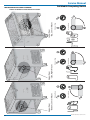
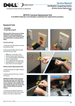
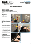
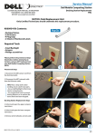
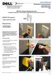
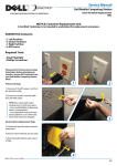
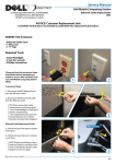
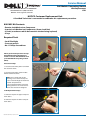
Service Manual
Dell Mobile Computing Station
Lock Replacement
CRU
CUSTOM SOLUTION FOR DELL BY ERGOTRON
FOR SERVICE CALL (800) 888-8458
OR VISIT www.ergotron.com/Dell
NOTICE: Customer Replacement Unit
A Certified Technician is not needed to undertake this replacement procedure.
K001055 Kit Contents:
• Exterior Lock Mechanism Component
• Interior Lock Mechanism Components (Screw, Lock Nut)
• 3 Pawls (use the one which best matches the one being replaced)
• 2 keys
Required Tools
• Small Flashlight
• Crescent wrench
• No. 1 Phillips Screwdriver
Please perform the preremoval steps
listed below before attempting to
install or remove ANY hardware from
your Dell Mobile Computing Station
(MCS).
1
2
Preremoval Steps
1. Disconnect the MCS power cord from
the electrical outlet.
2. Disconnect the MCS network cable
from the Ethernet outlet.
TIPS: Place a drop cloth under
working area to catch loose parts.
• Use a small flashlight to illuminate
interior compartments.
• Use magnetized tools to prevent
loosing fasteners or to retrieve fasteners that have been dropped.
3
Lock Replacement Steps
3. Unlock and open the upper compartment doors.
4. Unlock and open the lower compartment doors.
4
888-97-093-W-00 rev. A • 01/10
1/3
2/3
Exterior View
Interior View
Interior View
Upper Door
- Side, Right Mount
Exterior View
Upper Door
- Bottom, Center Mount
LOCK MECAHNISM ASSEMBLY DIAGRAM
Interior and Exterior Views Based on Location
Interior View
Exterior View
Lower Door
- Top, Center Mount
Service Manual
Dell Mobile Computing Station
888-97-093-W-00 rev. A • 01/10
Service Manual
Dell Mobile Computing Station
5. Remove the top nut* and pawl of the
interior lock component with a crescent wrench.
* In some cases instead of a nut,
there will be a small screw that can
be loosened with a no. 1 Phillips
screwdriver.
6. Remove the locknut of the interior lock compenent with a crescent
wrench.
Exterior
7. Remove and discard the exterior and
interior lock components.
8. Assemble the new interior lock component: stack the fasteners in the order
shown, (lock nut, pawl, screw)
NOTE: Apply Loctite® (if provided),
to lock nut and screw.
9. Insert the new interior lock component making sure that the pawl
is positioned relative to the exterior
component.
NOTE: Refer to the Assembly
Diagram on the previous page. The
relationship between exterior and
interior lock mechanism components is cruicial for proper function
of the lock.
Interior
Fastener Assembly
Interior Components
Nut*
Nut*
Pawl
Lock Nut
Pawl
Lock Nut
10. Secure the exterior and interior lock
components to each other by tightening the lock nut and screw using
a crescent wrench and no. 1 Phillips
screwdriver
11. Verify system operation.
* NOTE: in some cases there will be a screw instead of a nut.
LOCK REPLACEMENT
IS NOW COMPLETE
CUSTOM SOLUTION FOR DELL BY ERGOTRON
FOR SERVICE CALL (800) 888-8458
OR VISIT www.ergotron.com/Dell
888-97-093-W-00 rev. A • 01/10
3/3