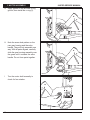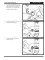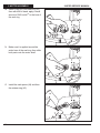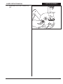
1
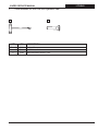
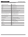
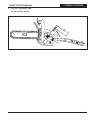
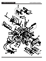
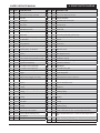
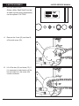
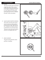
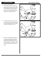
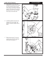
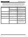
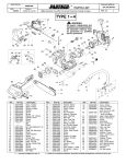
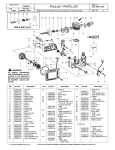
814PRO
SERVICE MANUAL
F/N 522803 Jul12
© 2012 ICS, Blount Inc.
814PRO SERVICE MANUAL
TABLE OF
TITLE
CONTENTS
SECTION
SECTION TITLE
SHOP MANUAL USE
2
1
TOOLS
3
2
SAW SPECIFICATIONS
4
3
SERIAL NUMBER LOCATION
5
4
SPARE PARTS DIAGRAM
6
5
MOTOR ASSEMBLY
8
6
WATER VALVE ASSEMBLY
24
7
TROUBLESHOOTING DIAGRAM30
F/N 522803 Jul12
PAGE NUMBER
© 2012 ICS, Blount Inc.
1
SHOP MANUAL USE
814PRO SERVICE MANUAL
Shop Manual Use
This manual contains all the technical information necessary for carrying out repairs on the
814 hydraulic saw. For safe, efficient work, it is of prime importance that the values indicated
be adhered to. Routine periodic maintenance is covered in the operator’s manual included with
each hyraulic saw.
General Shop Rules
• Always use the right tools for the job, otherwise components may be damaged.
• Use a plastic dead blow mallet to separate parts attached solidly to each other.
• Mark mating parts as a reassembly reference.
• Keep component parts together as a group. Assemble screws and nuts into appropriate
subgroups.
• When reassembling, clean all parts carefully, lubricate moving parts and replace all oil seals,
o-rings, gaskets, washers and self-locking nuts.
• For best results, use only original ICS® replacement parts.
SERVICING THE ICS® HYDRAULIC SAW: Servicing of hydraulic tools, other than routine
maintenance, must be performed by an authorized and certified dealer. For the nearest
authorized and certified dealer, call ICS® at the number listed on the back of this manual and
ask for a Customer Service Representative.
2
© 2012 ICS, Blount Inc.
F/N 522803 Jul12
814PRO SERVICE MANUAL
1
Tools available for the 814PRO Hydraulic Saw
1
1. TITLE
TOOLS
2
KEY
P/N
SERVICE
71572
TOOL KIT
1
71152
SCRENCH, 17-19 mm
2
73462
MAIN BEARING DRIVER TOOL
F/N 522803 Jul12
DESCRIPTION
© 2012 ICS, Blount Inc.
3
2. SPECIFICATIONS
814PRO SERVICE MANUAL
Specifications
4
Weight w/out bar and chain
15 lbs (10.25 kg)
Length
14.3 Inches (36.3 cm)
Height
11.3 inches (28.7 cm)
Width
9.2 inches (23.4 cm)
Hydraulic Supply Requirements (Max)
8 gpm (l/min) @ 2,500 psi (172 bar)
Hydraulic Fluid Requirements (Type)
Mobil DTE 13M or Equivalent
Water Pressure Requirements
Minimum: 20 psi (1.4 bar)
Recommended: 20 psi (1.4 bar)
Maximum: 160 psi (11 bar)
Water Flow Requirements
1 gpm
Operating Speed
5,700 rpm (avg. free running)
4,900 sfm (avg. free running chain)
Noise Level
88 dB @ 1 M (3 ft)
Vibration
3.5 m/sec² (front handle)
Ref. ISO standard no. 7505
Torque
95 in-lbs
Horsepower
11 hp
© 2012 ICS, Blount Inc.
F/N 522803 Jul12
814PRO SERVICE MANUAL
3. SERIAL
TITLE
# LOCATION
3 814PRO Hydraulic Saw
serial number series.
F/N 522803 Jul12
© 2012 ICS, Blount Inc.
5
4. SPARE PARTS DIAGRAM
814PRO SERVICE MANUAL
73
12
62
58
59
78
79
32
47
84
45
46
6
© 2012 ICS, Blount Inc.
F/N 522803 Jul12
814PRO SERVICE MANUAL
DESCRIPTION
4. SPARE PARTS DIAGRAM
KEY
P/N
KEY
P/N
DESCRIPTION
1
74514
HSH Cap Screw 10-24 x 1 1/4
46
71388 Tabbed Washer
2
74515
Rear Gear Housing Assembly
47
71940 Side Cover Replacement Kit
3
74516
Dowl Pin
48
74558 Flange Nut (M10)
4
74517
Bushing (4)
49
74559 Sprocket Side Cover Seal
5
74518
O-Ring
50
71383 814PRO Motor Shaft Replacement
6
74519
Idler Shaft
51
74561 Needle Roller
7
74520
Idler Gear
52
74562 HSH Cap Screw 5/15-18 x 3/4
8
74021
Wallwalker Pivot Pin
53
74563 Shaft Seal
9
74597
1/8 NPT Plug
54
74564 Seal Back Up Washer
10
74596
Wiper Seal
55
74591 Guard Flap Assembly (Not shown)
11
74522
Drive Gear (with Keyway)
56
74566 Guard Flap Mount
12
74523
On-Off Valve
57
74567 Spacer
13
74524
Hydraulic Valve Seal
58
74568 Bar Mount Cover Plate
14
74525
Spring Washer
59
74569 Front Stud
15
74526
Spring
60
74570 HSH Cap Screw 1/4-20 x 5/8
16
74527
Retaining Ring 1/2 External
61
74571 Machine Screw
17
74528
Plug Button
62
74572 Stat-O-Seal
18
74529
Roll Pin
63
74573 Bar Adjustment Nut
19
74530
Roll Pin
64
74019 Lanyard Assembly
20
74531
Valve Handle Assy (Includes: 31, 66)
65
74582 WallWalker Spring
21
74532
O-Ring
66
74583 WallWalker Arm (w/ Spring)
22
74533
Pigtail Hose Assembly
67
74574 Handle Bar Retainer
23
74534
1/2” Flush Face Coupler (M)
68
74575 Handle Bar
24
74535
1/2” Flush Face Coupler (F)
69
74584 Guard Mounting Bolt
25
74536
Water Hose Assembly
70
74585 Guard Mounting Washer
26
74537
Trigger
71
74586 Front Handguard
27
74538
Spring
72
74576 Washer
28
74539
Safety Catch (Trigger Lock-Out)
73
74577 HH Cap Screw 5/16-18 x 5/8, Zinc
29
74540
Rear Stud
74
74588 Handlebar Grip
30
74542
Roll Pin
75
74579 Nut 1/4-20 HHD LT SST
31
74543
O-Ring
76
74580 Spiral Pin
32
74544
O-Ring
77
74581 Spiral Pin
33
74545
Self Locking Retaining Ring
78
74493 Quad-Ring
34
74546
O-Ring
79
74565 Retaining Ring
35
74547
Water Valve Sleeve
80
74554 Shaft Bearing Race
36
74548
O-Ring
81
74498 O-Ring
37
74549
Pin
82
74495 Seal Washer
38
74550
Steel Ball
83
74494 V-Ring
39
74551
Spring
84
74496 Seal Ring
40
74552
O-Ring
85
74555 Retaining Ring
41
74553
Seal Cap
71152 Tensioning Scrench, Hydraulic Saws (not shown)
42
71386
Splined Sprocket Adaptor
71944 Water Valve Seal Kit (Incl: 31,32,34,36) (not shown)
43
71384
External Shaft Retaining Ring
44
74497
Seal Spacer
45
71385
Rim Sprocket
71945
Motor Shaft Seal Kit (Incl: 5,43,53,54,78,81,83) shown on
p.8
74061 Chain Tensioning Assembly (Incl: 61,62,63,75) (not shown)
75260 814 Rim Sprocket Upgrade Kit (not shown)
F/N 522803 Jul12
© 2012 ICS, Blount Inc.
7
5. MOTOR ASSEMBLY
5.1
814PRO SERVICE MANUAL
MOTOR SERVICING
Obtain a Motor Shaft Seal Kit so that
all seals exposed during disassembly
can be replaced. P/N 71945
A Remove the 2 nuts (51) and then lift
off the side cover (50).
B Lift off the bar (61) and chain (73). If
it is necessary to take tension off the
bar and chain, turn the screw (68)
counter clockwise.
8
© 2012 ICS, Blount Inc.
F/N 522803 Jul12
814PRO SERVICE MANUAL
5. MOTOR ASSEMBLY
C Remove the e-clip (no longer used),
or retaining ring (43) on current
models, and slide off items 43, 45
and 46.
Use retaining ring (43) for
replacement. P/N 71384 (e clip)
D Remove the retaining ring (43) and
then spacer (44).
E Remove the retaining ring (85) and
then items 81 thru 84.
Use a flat blade screwdriver to pry
the notched end out of recess. Lift
up and unwind from recess.
F/N 522803 Jul12
© 2012 ICS, Blount Inc.
9
5. MOTOR ASSEMBLY
814PRO SERVICE MANUAL
F Remove the eight capscrews (1) from
gear housing (2).
G Using a flat-blade screwdriver or
similar tool, gently pry the gear
housing away from the valve handle.
Lift the gear housing straight up. DO
NOT tilt the housing or pry on the
flat surface inside of the surrounding
groove. For prying, only use the
groove provided at the split between
the parts to prevent scratches on the
inner mating surfaces.
H Remove the two gears (7 & 11),
needle roller (51), and the
idler shaft (6).
10
© 2012 ICS, Blount Inc.
F/N 522803 Jul12
814PRO SERVICE MANUAL
I
Remove the large face seal o-ring (5)
while being careful not to damage the
o-ring groove or surrounding surface.
J
While protecting the motor surface
of the valve handle from damage,
tap lightly on the small diameter end
(gear side) of the motor shaft (50)
to remove it.
5. MOTOR ASSEMBLY
K To remove the bearing from the
shaft, press on the outside end
(sprocket end) of the motor shaft
while supporting the outer race of the
bearing. Discard the old bearing.
F/N 522803 Jul12
© 2012 ICS, Blount Inc.
11
5. MOTOR ASSEMBLY
L
814PRO SERVICE MANUAL
Remove the retaining ring (79) at
the bottom of the bearing bore.
Remove the seal backup washer
(54). Remove the quad ring (78) and
o-ring (53) using the appropriate
o-ring service tools. Discard the quad
ring and o-ring.
M The bushings (4) can be removed
using the collet from the bearing
puller kit.
12
© 2012 ICS, Blount Inc.
F/N 522803 Jul12
814PRO SERVICE MANUAL
5.2
MOTOR INSPECTION AND
CLEANING
Inspect and clean all parts as follows:
5. MOTOR ASSEMBLY
ACLEANING
Clean all parts with a degreasing
solvent. Blow dry with compressed
air and wipe clean. Use only lint-free
cloths.
B GEAR HOUSING
The chamber bores and bottoms
around the shaft bushings should be
polished and not rough or grooved. If
the bushing bores are yellow-bronze,
replace them and investigate the
cause of wear.
The flat surfaces around the chamber
and bolt holes should be flat and free
of nicks or burrs that could cause
misalignment or leaks.
CBUSHINGS
The inside of the bushings should
be gray with some bronze showing
through. If significant yellow-bronze
shows, replace the bushings.
F/N 522803 Jul12
© 2012 ICS, Blount Inc.
13
5. MOTOR ASSEMBLY
814PRO SERVICE MANUAL
DGEARS
The drive and idler gears should have
straight tips without nicks, square
tooth ends and a smooth even polish
on the teeth and end faces. Check
for cracks between the drive gear
keyway and gear tooth root. Replace
the gear if cracks are present.
E VALVE HANDLE MOTOR SURFACE
The surface near the gears should
show two interconnecting polished
circles without a step. The bottom of
the o-ring groove should be smooth
as should the rest of the flat surface.
The bore for the shaft seal should be
smooth or oil leakage may occur.
F GEAR HOUSING
14
The gear housing should be clean
and free of scratches.
© 2012 ICS, Blount Inc.
F/N 522803 Jul12
814PRO SERVICE MANUAL
5. MOTOR ASSEMBLY
GSHAFTS
The shaft diameter at the bearing
and seal locations must be smooth.
Grooves, roughness or a reduced
diameter indicate fluid contamination
or damaged bushings. Grit particles
may have been imbedded in the
bushings grinding into the hardened
shaft. If abnormal shaft wear as
above occurs (more than normal
polishing), replace both the shaft and
associated bushings.
Also check the hydraulic system for
excess contamination in the fluid
and for filter condition. Operating
conditions may require changing from
a 25-micron filter to an oversized
10-micron filter.
See power pack manual for
instructions.
F/N 522803 Jul12
© 2012 ICS, Blount Inc.
15
5. MOTOR ASSEMBLY
5.3
814PRO SERVICE MANUAL
MOTOR REASSEMBLY
A Grease and carefully install a new
quad ring (78) into the seal liner (54).
Grease and install a new o-ring (53)
onto the seal liner. Install the seal
liner into the valve handle assembly.
Replace the retaining ring (79).
B To replace the bearing (80) onto the
motor shaft (50), support the bearing
inner race and press the motor shaft
through the bearing inner race.
C Place the valve handle assembly on
a smooth clean arbor press surface
(protected from damage) with the
large bearing bore facing up. Position
the valve handle so a clearance hole
exists for the insertion of the motor
shaft.
16
© 2012 ICS, Blount Inc.
F/N 522803 Jul12
814PRO SERVICE MANUAL
5. MOTOR ASSEMBLY
D Apply grease to the motor shaft,
keyway and bushing and then insert
the motor shaft through the shaft
seal. Using a socket with a diameter
equal to the bearing O.D., press the
bearing and motor shaft into place.
Press only on the outer race.
E Install the needle roller (51) in the
keyway of the motor shaft. Use
grease to keep the needle roller in
place.
F Slide the drive gear (11) over the
needle roller and shaft. Install the
idler shaft (6) and gear (7).
F/N 522803 Jul12
© 2012 ICS, Blount Inc.
17
5. MOTOR ASSEMBLY
814PRO SERVICE MANUAL
G Apply grease to the face seal o-ring
groove; then install the o-ring (5).
H Note the screw hole pattern on the
rear gear housing and the valve
handle. They will only assemble one
way. With all parts aligned, carefully
slide the gear housing assembly over
the gears until it contacts the valve
handle. Do not force parts together.
I
18
Turn the motor shaft manually to
check for free rotation.
© 2012 ICS, Blount Inc.
F/N 522803 Jul12
814PRO SERVICE MANUAL
J
Install the eight capscrews (1) and
then recheck rotation. Snug screws
and check shaft rotation again. For
final torque, turn 1/4 rotation past
snug and recheck rotation.
K
Install the o-ring (81). Push in until it
contacts the bearing face.
L
Install seal washer (82) and the
retainer ring (85).
F/N 522803 Jul12
5. MOTOR ASSEMBLY
© 2012 ICS, Blount Inc.
19
5. MOTOR ASSEMBLY
814PRO SERVICE MANUAL
M Install v-ring (83) onto seal ring (84)
then with both in hand, apply a small
TM
amount of 242 Loctite to the bore of
the seal ring
N Make sure it is applied around the
entire bore of the seal ring, then slide
both parts onto the motor shaft.
O Install the seal spacer (44) and then
the retainer ring (43).
20
© 2012 ICS, Blount Inc.
F/N 522803 Jul12
814PRO SERVICE MANUAL
5. MOTOR ASSEMBLY
P Install items 42.45 and. Retainer clip
(43).
F/N 522803 Jul12
© 2012 ICS, Blount Inc.
21
5. MOTOR ASSEMBLY
5.4
814PRO SERVICE MANUAL
BAR & CHAIN AND CHAIN GUARD
ASSEMBLY
A Back the bar adjustment nut (63) off
by turning the adjustment screw (61)
counter clockwise.
B Install the chain guide plate (58) over
the studs (29, 59).
C Install the chain onto the bar. Place
the bar (with chain) over the studs
making sure the chain is looped
around the sprocket and the bar
adjustment nut is seated in the hole
on the bar.
22
© 2012 ICS, Blount Inc.
F/N 522803 Jul12
814PRO SERVICE MANUAL
5. MOTOR ASSEMBLY
D While pulling up on the bar and
chain, turn the adjustment screw (61)
clockwise to take the slack out of the
chain.
E Install the side cover (47) and the 2
nuts (48). Hand tighten the 2 nuts
and then back them off 1/4 turn.
F When adjustments are completed, be
sure to tighten the nuts.
F/N 522803 Jul12
© 2012 ICS, Blount Inc.
23
6. WATER VALVE ASSEMBLY
6
This section covers the service
instructions for the water and
hydraulic valve assembly
6.1
PRIOR TO DISASSEMBLY
814PRO SERVICE MANUAL
A Clean exterior of the tool.
B Obtain a Water Valve Seal Kit so that
all seals exposed during disassembly
can be replaced. P/N 71944
6.2
ON-OFF VALVE SERVICING
TRIGGER AND SAFETY CATCH
REMOVAL & INSTALLATION
A Remove the plug button (19) from
the top of the handle by prying under
the edge and then pulling it from the
handle.
B Drive the roll pins (18) out of the
handle assembly using a 3/16 in./4
mm diameter punch. Press the safety
catch (28) and remove the
trigger (26).
C The safety catch (28) can be
removed at this time by driving
out the 3/16 inch roll pin (19).
24
© 2012 ICS, Blount Inc.
F/N 522803 Jul12
814PRO SERVICE MANUAL
6.3
6. WATER VALVE ASSEMBLY
VALVE SPOOL REMOVAL &
INSTALLATION
A Unscrew the seal cap (41) and
remove it, the o-ring (40), the
spring (39), and the steel ball (38).
B Remove the plug button (17), wiper
seal (10) and the retaining ring (16)
from handle. The wiper seal must be
replaced.
Lift out the valve spool assembly
(12-15).
F/N 522803 Jul12
© 2012 ICS, Blount Inc.
25
6. WATER VALVE ASSEMBLY
814PRO SERVICE MANUAL
C Using a 1/2 in./12.7 mm diameter
wood dowel, place the dowel into the
valve spool bore from the plug button
end of the handle.
D Push the dowel against the water
valve sleeve (32-37) to push the
water sleeve out.
Remove o-ring(31) from the spool
bore of the handle
If only the water valve seal needs
replacing, use a heavy gauge wire to
insert into the bottom of the valve to
extract.
26
© 2012 ICS, Blount Inc.
F/N 522803 Jul12
814PRO SERVICE MANUAL
6. WATER VALVE ASSEMBLY
6.4REASSEMBLY
A Inspect the spool bore of the
handle and the outer surfaces of
the spool for damage. Some light
surface scratches will be noticeable.
Grooves, roughness or a reduced
diameter indicate fluid contamination.
If abnormal wear is present (more
than normal polishing), replace both
the spool and the handle.
B Apply grease and install a new
o-ring (13) onto the ON/ OFF valve
(12).
C Apply grease and install new o-ring
(31) into the spool bore of the handle.
F/N 522803 Jul12
© 2012 ICS, Blount Inc.
27
6. WATER VALVE ASSEMBLY
814PRO SERVICE MANUAL
D Apply grease and install new o-rings
(32, 34, 36) onto the water valve
sleeve (35). Insert pin (37) and self
locking retaining ring (33).
E Install the water valve sleeve (35) into
the valve handle.
F Install the steel ball (38), spring (39),
and seal cap (41). Make sure a new
o-ring (40) is installed onto the seal
cap.
G If the spring washer (14) and spring
(15) were removed from the ON/OFF
valve, reinstall them. Lubricate the
ON/ OFF valve with hydraulic fluid
and install it into the valve handle.
Secure it in place with the roll pin
(18).
28
Install new wiper seal (10).
© 2012 ICS, Blount Inc.
F/N 522803 Jul12
814PRO SERVICE MANUAL
6. WATER VALVE ASSEMBLY
H Install the safety catch (28) making
sure the spring (27) is positioned
properly. Make sure the pin (30) is in
place. Secure the safety catch with
the roll pin (19).
I
Install the trigger (26) and secure
with the roll pins (18).
J
Replace the plug button (17) and test
the action of the safety catch and
trigger.
F/N 522803 Jul12
© 2012 ICS, Blount Inc.
29
7. TROUBLESHOOTING
TITLE
7
814PRO SERVICE MANUAL
If symptoms of poor performance develop, the following chart can be used as
a guide to correct the problem. When diagnosing faults in operation of the tool,
always check that the hydraulic power source is supplying the correct hydraulic
flow and pressure to the tool as listed in the table. Use a flowmeter known to be
accurate. Check the flow with the hydraulic oil temperature at least 80°F/27°C.
SYMPTOM
CAUSE
REMEDY
Tool does not run.
Hydraulic power source not functioning
correctly.
Check power source for proper flow
and pressure (7-9 gpm 26-34 lpm at
2000 psi/140 bar.
Coupler or hoses blocked.
Remove obstruction.
Mechanical failure.
Have tool serviced by authorized
dealer.
Tool runs backwards.
Pressure and return lines incorrectly
connected.
Correct hose connections. Motor shaft
rotates counterclockwise as viewed
from the end of the motor shaft.
Trigger hard to press.
Pressure & return hose reversed.
Connect for proper flow direction. Motor
shaft must rotate clockwise.
Back-pressure too high.
Should not exceed 250 psi/17 bar @
9gpm/34 lpm measured at the end of
the tool’s operating hoses.
Leakage around drive sprocket.
Motor shaft seal failure.
Have unit serviced.
No water discharge at bar.
Blocked port(s) in bar.
Turn off hydraulic supply. Remove bar
and chain and clean bar thoroughly.
Blow ports with compressed air.
Blocked inlet or outlet.
Turn off hydraulic supply. Remove bar
and chain. Make sure water supply
is on. Press trigger to see if water
exits near bar adjustment nut area (a
small port). If no water exits, have unit
serviced.
30
© 2012 ICS, Blount Inc.
F/N 522803 Jul12
814PRO SERVICE MANUAL
ICS, Blount Inc.
4909 SE International Way
Portland, OR 97222
Tel 800-321-1240 Fax 503-653-4393
icsbestway.com