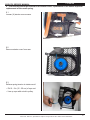
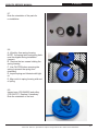
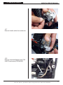
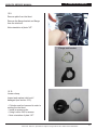
1
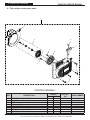
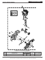
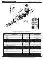
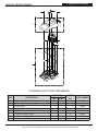
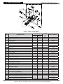
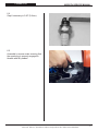
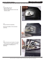
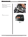
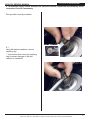
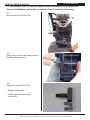
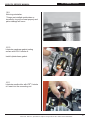
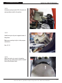
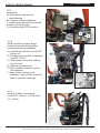
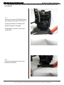
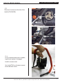
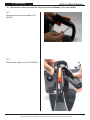
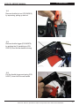
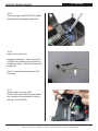
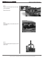
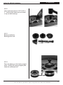
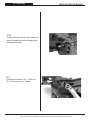
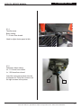
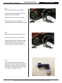
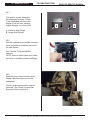
695GC/F4
SERVICE MANUAL
©2012 ICS - Blount Inc, Specifications subject to change without notice. REV11272012 P/N 546529
695GC/F4 SERVICE MANUAL
SECTION
TABLE OF CONTENTS
SECTION TITLE
PAGE NUMBER
SERVICE MANUAL USE
3
1
TOOLS
4
2
SAW SPECIFICATIONS
5
3
SERIAL NUMBER LOCATION
6
4
SPARE PARTS DIAGRAM (TORQUE SPECIFICATIONS AND LOCTITE
5
AIR INTAKE
19
6
SPARK PLUG
20
7
SIDE COVER & TENSIONER
22
8
CLUTCH & RIM SPROCKET
24
9
STARTER SYSTEM
30
10
CARBURETOR REMOVAL
35
11
MUFFLER/W BAR STUD
39
12
MUFFLER/W BAR STUD
40
13
IGNITION MODULE
41
14
STOP SWITCH
42
15
WATER HOSE
44
16
CYLINDER & PISTON
45
17
BOTTOM GUARD/FRONT HANDLE
51
18
REAR HANDLE
53
19
FUEL TANK & COMPONENTS
57
20
CRANKCASE
63
21
CARBURETOR TUNING
77
22
IDLE SPEED ADJUSTMENT
80
23
TROUBLESHOOTING DIAGRAMS
81
24
TROUBLESHOOTING: FUEL SYSTEM
83
25
TROUBLESHOOTING: CRANKCASE LEAKS
87
®
APPLICATION)
7
APPENDIX
1. SPARK PLUG REFERENCE GUIDE
©2012 ICS - Blount Inc, Specifications subject to change without notice. REV11272012 P/N 546529
89
2
SERVICE MANUAL USE
695GC/F4 SERVICE MANUAL
Service Manual Use
This manual contains all the technical information necessary for carrying out repairs on the
695GC/F4 saw. For safe, efficient work, it is of prime importance that the values indicated be
adhered to. Routine periodic maintenance is covered in the operator’s manual included with
each saw.
General Service Rules
•
Always use the right tools for the job, otherwise components may be damaged.
•
Use a plastic dead blow mallet to separate parts attached solidly to each other.
•
Mark mating parts as a reassembly reference.
•
Keep component parts together as a group. Assemble screws and nuts into appropriate
subgroups.
•
When reassembling, clean all parts carefully, lubricate moving parts and replace all oil
seals, o-rings, gaskets, washers and self-locking nuts.
•
For best results, use only original ICS® replacement parts.
General Recommendations
•
Some procedures in this manual require the use of special tools. These are noted in the
service manual.
•
Detailed carburetor maintenance and overhaul information is available in Walbro’s
Diaphragm Carburetor Service Manual. Walbro can be contacted at http:\\www.walbro.com
or by calling 1.989.872.2131.
©2012 ICS - Blount Inc, Specifications subject to change without notice. REV11272012 P/N 546529
3
1. TOOLS
695GC/F4 SERVICE MANUAL
1
Key #
2
4
3
5
6
7
8
9
10
11
12
13
14
15
16
17
18
19
20
Part No.
Description
1
71541
Pressure Gauge Bulb
2
71543
Cylinder Assembly Clamps & Piston Stop
3
71565
Electronic Tachometer
4
73425
Fuel Tank Pressure Cap
5
546191
Workshop Key Torx T27
6
546192
Test Spark Plug
7
546193
Air Gap Gauge
8
546194
Flywheel Puller
9
547277
Piston Stop
10
546196
Wrist Pin Punch
11
546197
Cylinder Seal, Exhaust
12
546198
Cylinder Seal, Inlet Port
13
546289
Puller, Sealing Ring
14
546291
Assembly Punch
15
546292
Universal Puller
16
546293
Grip Plate
17
546294
Bearing Puller
18
546295
Bearing Press
19
546307
Screwdriver, Idle
20
546659
Clutch Tool
not shown 70249
14T Bar Nose Sprocket Repair Kit (for 695GC)
not shown 530046
FORCE4™ Bar Nose Sprocket Repair Kit (for 695F4)
not shown 505882
2-Stroke Oil, 25:1 Mix, 5.2 oz. (158 ml) (6-pack)
not shown 505883
2-Stroke Oil, 25:1 Mix, 5.2 oz. (158 ml) (24-pack)
©2012 ICS - Blount Inc, Specifications subject to change without notice. REV11272012 P/N 546529
4
2. SPECIFICATIONS
695GC/F4 SERVICE MANUAL
Specifications
Engine Type
2-stroke, Air Cooled
Displacement
5.7 cu-in (94 cc)
Horsepower
6.4 hp (4.8 kW) @ 9000 rpm
Torque
50.4 in-lbs (5.7 Nm) @ 7,200 rpm
Engine Speed
9,300 +/- 150 rpm (max)
2,700 +/- 100 rpm (idle)
Piston ring gap (Maximum)
Weight
Dimensions
.04 in/1.0mm
21 lbs (9.5 kg) powerhead only
18 in (46 cm) length
14 in (36 cm) height
12 in (30 cm) width
Carburetor
Walbro RWJ-5A
Air Filtration
Water resistant polyester
Starter
Dust and water resistant
Ignition
Special water resistant electronic ignition
Spark plug type
NGK BPMR7A or Champion RCJ6Y
Electrode gap 0.020 in (0.5 mm)
Clutch
Centrifugal, three shoe, three spring
Fuel Mix Ratio
25:1 (4%) gasoline-to-oil
Fuel Capacity
0.26 gallon (1 liter)
Water Supply
Minimum 20 psi (1.5 bar)
Noise Level
112 dB(A) at 3 ft (1 m)
Vibration Level
3.9 m/s2 (front handle)
4.1 m/s2 (rear handle)
©2012 ICS - Blount Inc, Specifications subject to change without notice. REV11272012 P/N 546529
5
695GC/F4 SERVICE MANUAL
3. SERIAL NUMBER LOCATION
3. This section shows the single location of the serial number.
©2012 ICS - Blount Inc, Specifications subject to change without notice. REV11272012 P/N 546529
6
4. SPARE PARTS DIAGRAM
695GC/F4 SERVICE MANUAL
4. This section covers spare parts.
1
8
2
5
6
3
4
3
7
7
STARTER ASSEMBLY
KEY
1
2
3
4
5
6
7
8
DESCRIPTION
STARTER COVER ASSEMBLY
STARTER PULLEY KIT
SCREW
RECOIL SPRING
STARTER CORD
STARTER HANDLE
SCREW
STARTER COVER SHIELD
TORQUE
Nm
in‑lbs.
LOCTITE®
242
PART NUMBER
x
7-9
60 - 78
©2012 ICS - Blount Inc, Specifications subject to change without notice. REV11272012 P/N 546529
544013
544127
543974
544021
544023
544024
544012
544026
7
4. SPARE PARTS DIAGRAM
695GC/F4 SERVICE MANUAL
1
2
3
4
9
5
6
7
11
10
12
8
FLYWHEEL & IGNITION ASSEMBLY
KEY
1
2
3
4
5
6
7
8
9
10
11
12
DESCRIPTION
TORQUE
Nm
in‑lbs.
STOP SWITCH SCREW
STOP SWITCH
STOP SWITCH CABLE
SPARK PLUG CAP
SPARK PLUG
PROTECTIVE SLEEVE
IGNITION MODULE
IGNITION MODULE SCREW
10 - 12 89 - 105
FLYWHEEL
STARTER PAWL KIT (INCL. TWO OF EACH ITEM)
FLYWHEEL WASHER
FLYWHEEL NUT
25 - 30 216 - 264
LOCTITE®
242
PART NUMBER
x
x
©2012 ICS - Blount Inc, Specifications subject to change without notice. REV11272012 P/N 546529
544030
544031
544032
544033
544034
544035
544036
544038
544053
544125
544058
544059
8
4. SPARE PARTS DIAGRAM
695GC/F4 SERVICE MANUAL
11
14
1
2
3
12
4
15
5
6
13
7
10
8
9
16
CLUTCH ASSEMBLY & WALLWALKER®
KEY
DESCRIPTION
TORQUE
Nm
in‑lbs.
LOCTITE®
242
PART NUMBER
1
RETAINING RING
543905
2
SPLIT RETAINER
543906
3
SPACER
543907
4
695F4 FORCE4™ SPROCKET
525496
4
695GC RIM SPROCKET
70949
5
CLUTCH CUP
543909
6
NEEDLE BEARING
7
BAR BRACKET SCREW
x
543911
8
CRANK CASE BOLT
x
543912
543910
9
WALLWALKER
544130
10
WALLWALKER SCREW
543920
11
WATER PIPE
12
WATER PIPE SCREW
13
BAR BRACKETS
543916
14
CLUTCH ASSEMBLY
547856
15
CLUTCH SPRING
543928
16
SHIELD
544137
®
®
543915
x
©2012 ICS - Blount Inc, Specifications subject to change without notice. REV11272012 P/N 546529
546548
9
4. SPARE PARTS DIAGRAM
695GC/F4 SERVICE MANUAL
1
2
3
5
5
4
5
6
SIDE COVER & TENSIONER ASSEMBLY
KEY
DESCRIPTION
TORQUE
Nm
in‑lbs.
LOCTITE®
PART NUMBER
242
1
SIDE COVER ASSEMBLY
2
SIDE COVER NUT
543899
3
SIDE COVER NUT CIRCLIP
543901
4
TENSIONER COVER PLATE SCREW
543902
5
SCREW, SIDE COVER CAP
6
TENSIONER
27 - 34 240 - 300
543900
x
543903
543904
©2012 ICS - Blount Inc, Specifications subject to change without notice. REV11272012 P/N 546529
10
4. SPARE PARTS DIAGRAM
695GC/F4 SERVICE MANUAL
1
1
1
2
1
3
8
5
4
11
9
1
1
6
1
7
4
12
1
13
9
7
14
6
10
4
13
CYLINDER & EXHAUST ASSEMBLIES
KEY
DESCRIPTION
TORQUE
Nm
in‑lbs.
15 - 18 132 - 156
LOCTITE®
PART NUMBER
242
x
1
CYLINDER/MUFFLER SCREW
2
PISTON/CYLINDER KIT
545873
3
HEAT DEFLECTOR
543844
4
MUFFLER GASKET
543938
5
MUFFLER
543845
6
LOWER MUFFLER MOUNTING SCREW
7
MUFFLER MOUNTING WASHER
543847
8
DECOMPRESSION VALVE
543848
9
CYLINDER BASE GASKET
543937
10
NEEDLE BEARING
543949
x
543942
543846
11
MUFFLER MOUNT KIT
543950
12
GASKET KIT
543936
13
SEALING RING
543931
14
CRANKCASE GASKET
543933
©2012 ICS - Blount Inc, Specifications subject to change without notice. REV11272012 P/N 546529
11
4. SPARE PARTS DIAGRAM
695GC/F4 SERVICE MANUAL
12
1
2
3
5
4
7
4
6
11
6
8
3
3
9
5
10
3
CRANKCASE ASSEMBLY
KEY
DESCRIPTION
TORQUE
Nm
in‑lbs.
LOCTITE®
242
PART NUMBER
1
CRANKCASE ASSEMBLY
2
CRANKCASE SCREW
3
SEALING RING
543931
4
GUIDE PIN
543932
5
CRANKCASE GASKET
543933
6
MAIN BEARING
543934
7
RUBBER BUSHING
543935
8
GASKET KIT
543936
9
CYLINDER BASE GASKET
543937
10
MUFFLER GASKET
543938
11
BAR STUD KIT
12
BAR BRACKET NUT
543929
12 - 14
106 - 124
x
x
©2012 ICS - Blount Inc, Specifications subject to change without notice. REV11272012 P/N 546529
543930
544129
543941
12
4. SPARE PARTS DIAGRAM
695GC/F4 SERVICE MANUAL
1
2
3
4
3
2
CRANKSHAFT ASSEMBLY
KEY
DESCRIPTION
TORQUE
Nm
in‑lbs.
LOCTITE®
PART NUMBER
242
1
CRANKSHAFT ASSEMBLY
543952
2
MAIN BEARING
543934
3
CRANKSHAFT SHIELD
543953
4
NEEDLE BEARING
543949
©2012 ICS - Blount Inc, Specifications subject to change without notice. REV11272012 P/N 546529
13
4. SPARE PARTS DIAGRAM
695GC/F4 SERVICE MANUAL
1
COMPLETE ENGINE ASSEMBLY
KEY
1
DESCRIPTION
CRANKCASE W/PISTON & CYL COMPLETE
TORQUE
Nm
in‑lbs.
LOCTITE®
PART NUMBER
242
©2012 ICS - Blount Inc, Specifications subject to change without notice. REV11272012 P/N 546529
544121
14
4. SPARE PARTS DIAGRAM
695GC/F4 SERVICE MANUAL
16
13
14
15
11
4
9
17
6
12
4
U
8
7
5
10
3
2
1
CARBURETOR & INTAKE ASSEMBLIES
KEY
DESCRIPTION
TORQUE
Nm
in‑lbs.
LOCTITE®
242
PART NUMBER
1
INLET BOOT CLAMP
544069
2
INLET BOOT
544070
3
FLANGE
544071
4
FLANGE CLUTCH SIDE SCREW
5
FLANGE BRACKET
6
SCREW
7
SEPARATOR PLATE
544074
8
CARBURETOR (WALBRO RWJ-5A)
544075
9
THROTTLE CABLE LEVER
544111
10
ADJUSTMENT GUIDE
544116
11
MANIFOLD BRACKET
544112
12
AIR INTAKE MANIFOLD
544113
13
AIR FILTER BRACKET
544114
14
CARBURETOR MOUNTING SCREW
x
544072
544073
x
x
544065
544115
15
THROTTLE CABLE ASSEMBLY
543975
16
CHOKE LEVER
544117
17
CARBURETOR REPAIR KIT
544118
©2012 ICS - Blount Inc, Specifications subject to change without notice. REV11272012 P/N 546529
15
4. SPARE PARTS DIAGRAM
695GC/F4 SERVICE MANUAL
2
1
2
1
3
4
5
6
6
8
8
7
8
CYLINDER & AIR FILTER ASSEMBLIES
KEY
1
DESCRIPTION
FILTER COVER REAR SCREW
TORQUE
Nm
in‑lbs.
LOCTITE®
PART NUMBER
242
3.5
31
544060
2
20
544061
2
FILTER COVER FRONT SCREW
3
FILTER COVER
544062
4
AIR INTAKE INSERT
544063
5
AIR FILTER
544064
6
CYLINDER COVER SCREW
7
CYLINDER COVER ASSEMBLY
544066
8
CYLINDER COVER SEALS
544067
x
©2012 ICS - Blount Inc, Specifications subject to change without notice. REV11272012 P/N 546529
544065
16
4. SPARE PARTS DIAGRAM
695GC/F4 SERVICE MANUAL
2
22
4
3
8
6
7
(76mm)
9
5
(102mm)
8
10
11
12
23
1
13
24
14
15
18
16
17
20
2
19
21
26
25
23
23
FUEL TANK ASSEMBLY
KEY
DESCRIPTION
TORQUE
Nm
in‑lbs.
LOCTITE®
242
PART NUMBER
1
FUEL TANK ASSEMBLY
543812
2
PARALLEL PIN
543813
3
CABLE LEVER
543814
4
THROTTLE LOCK OUT LEVER
543815
5
REAR HANDLE COVER
543816
6
CLIP
543818
7
FUEL LINE
543993
8
CHECK VALVE TUBE
543994
9
CHECK VALVE
543969
10
HOSE CLAMP
543970
11
FUEL FILTER
543971
12
TANK VENT ASSEMBLY
544990
13
TANK VENT FITTING
544122
14
REAR HANDLE GROUND SUPPORT
543972
15
PURGE BULB
543973
16
REAR HANDLE SCREW
543974
17
THROTTLE CABLE ASSEMBLY
543975
18
THROTTLE TRIGGER
543976
19
TRIGGER SPRING
543977
20
PURGE BULB TUBE
543995
21
GROMMET
543978
22
GAS TANK CAP ASSEMBLY
543979
23
SHOCK ABSORBER SCREW
x
543981
24
SHOCK ABSORBER CLUTCH SIDE
x
543982
25
SHOCK ABSORBER FRONT
x
543983
26
SHOCK ABSORBER FLYWHEEL SIDE
x
543984
©2012 ICS - Blount Inc, Specifications subject to change without notice. REV11272012 P/N 546529
17
4. SPARE PARTS DIAGRAM
695GC/F4 SERVICE MANUAL
2
6
8
7
9
1
10
9
10
5
12
4
13
3
10
11
13
WATER DELIVERY SYSTEM
KEY
DESCRIPTION
TORQUE
Nm
in‑lbs.
LOCTITE®
PART NUMBER
242
1
WATER HOSE VALVE ASSEMBLY
543996
2
HOSE HANGER
547969
3
WATER HOSE WITH PROTECTIVE COVERING
543999
4
CLAMP, WATER HOSE TUBE SIDE
544000
5
CLAMP, WATER HOSE VALVE SIDE
544001
6
FRONT HANDLE
544002
7
SHOCK ABSORBER, FRONT HANDLE
544003
8
SCREW, SHOCK ABSORBERS
9
CLIP, FRONT HANDLE
10
SCREW, FRONT HANDLE
11
GUARD FLAP
544010
12
BACKING PLATE, GUARD FLAP
544011
13
SCREW, GUARD FLAP
x
543981
544008
x
x
544009
544012
©2012 ICS - Blount Inc, Specifications subject to change without notice. REV11272012 P/N 546529
18
5. AIR INTAKE
695GC/F4 SERVICE MANUAL
5. This section covers the removal, inspection, and assembly of the air intake.
5.1
Loosen the air filter cover screws and
remove the air filter cover.
5.2
Loosen air filter screw.
• Inspect air filter for dirt or damage.
• Replace with P/N 544064.
©2012 ICS - Blount Inc, Specifications subject to change without notice. REV11272012 P/N 546529
19
695GC/F4 SERVICE MANUAL
6. SPARK PLUG
6. This section covers the removal, inspection and installation of the spark plug.
6.1
Remove the spark plug cap.
6.2
Remove the spark plug.
6.3
Inspect spark plug.
• If it’s dirty, clean with a wire brush.
• Replace spark plug if fouled or
erroded. USE NGK BRMR7A or
Champion RCJ6Y.
©2012 ICS - Blount Inc, Specifications subject to change without notice. REV11272012 P/N 546529
20
6. SPARK PLUG
695GC/F4 SERVICE MANUAL
6.4
Gap if necessary to 0.20” (0.5mm).
6.5
Assemble in reverse order ensuring that
the spark plug is properly engaged in
threads and fully seated.
©2012 ICS - Blount Inc, Specifications subject to change without notice. REV11272012 P/N 546529
21
7.SIDE COVER & TENSIONER
695GC/F4 SERVICE MANUAL
7. This section covers side cover removal, side cover nut removal, inspection and assembly.
7.1
Loosen side cover nut.
• Remove side cover.
• Remove tensioner plate screws and
tensioner plate.
7.2
Remove tensioner assembly.
Note the orientation of the tensioner
assembly.
7.3
Inspect tensioner and replace if needed.
• Clean tensioner threads and liberally
apply grease to threads prior to
assembly.
©2012 ICS - Blount Inc, Specifications subject to change without notice. REV11272012 P/N 546529
22
7.SIDE COVER & TENSIONER
695GC/F4 SERVICE MANUAL
7.4
Inspect side cover, nut and circlip.
Replace if damaged.
Circlip can be removed with a large
flathead screwdriver.
7.5
Assemble in reverse order.
©2012 ICS - Blount Inc, Specifications subject to change without notice. REV11272012 P/N 546529
23
8. CLUTCH & RIM SPROCKET
695GC/F4 SERVICE MANUAL
8. This section covers clutch removal, rim sprocket removal, inspection and assembly. Refer
to sections 5 and 6 if necessary.
Rim sprocket removal procedure.
8.1
Using flat head screwdriver, remove
retaining ring.
* Use caution when removing retaining
ring to prevent damage to the split
retainer or crankshaft.
©2012 ICS - Blount Inc, Specifications subject to change without notice. REV11272012 P/N 546529
24
8. CLUTCH & RIM SPROCKET
695GC/F4 SERVICE MANUAL
8.2
Remove the split retainer and spacer.
8.3
Inspect rim sprocket and replace if
necessary (P/N 70949).
• Replace if the rim sprocket teeth are
worn to points as shown on right.
8.4
Rim sprocket assembly.
• Assemble in reverse order.
©2012 ICS - Blount Inc, Specifications subject to change without notice. REV11272012 P/N 546529
25
695GC/F4 SERVICE MANUAL
8. CLUTCH & RIM SPROCKET
8.5
Remove clutch cup and needle bearing.
• Apply grease to needle bearing prior to
reinstalling.
8.6
Clutch removal.
• Remove clutch cup & rim sprocket first.
8.7
Insert piston stop tool into spark plug
hole.
©2012 ICS - Blount Inc, Specifications subject to change without notice. REV11272012 P/N 546529
26
8. CLUTCH & RIM SPROCKET
695GC/F4 SERVICE MANUAL
8.8
Remove clutch with clutch tool
(P/N 546659).
• Rotate clockwise to remove clutch
(clutch is left-handed thread).
8.9
Clutch is marked with arrow (off) for
direction of removal.
8.10
Inspect clutch shoes (P/N 543927)
for excessive wear or damage.
©2012 ICS - Blount Inc, Specifications subject to change without notice. REV11272012 P/N 546529
27
695GC/F4 SERVICE MANUAL
8. CLUTCH & RIM SPROCKET
8.12
Height of clutch shoes should not be less
than 1 mm.
8.12
Inspect and clean springs if necessary.
©2012 ICS - Blount Inc, Specifications subject to change without notice. REV11272012 P/N 546529
28
8. CLUTCH & RIM SPROCKET
695GC/F4 SERVICE MANUAL
8.13
Remove the springs.
• Set into a vice to hold in place.
• Place a flat head screwdriver or flat
tipped rod against the spring hook.
• Tap lightly at the end of the screwdriver
or rod. This will cause the spring hook
to detach.
• Push the spring out.
• Repeat with the remaining two springs.
8.14
Fit clutch shoes.
• Slide the spring into the narrower
section of the clutch shoe first.
NOTE: All spring hooks should point the
same direction as the word “OFF”. See
illustration at right for an example.
8.15
Fit springs.
• Turn the clutch so the word “OFF” is
facing down.
• Push the spring hook into its hole by
using a pointed tool.
©2012 ICS - Blount Inc, Specifications subject to change without notice. REV11272012 P/N 546529
29
9. STARTER
695GC/F4 SERVICE MANUAL
9. This section covers the removal of the starter cover, replacement of the starter rope and
replacement of the recoil spring.
9.1
Loosen (4) starter cover screws.
9.2
Remove starter cover from saw.
9.3
Relieve spring tension in starter recoil.
• Pull 6 - 8 in (15 - 20 cm) of rope out.
• Line up rope with notch in pulley.
©2012 ICS - Blount Inc, Specifications subject to change without notice. REV11272012 P/N 546529
30
9. STARTER
695GC/F4 SERVICE MANUAL
9.4
Rotate pulley shaft counter clockwise,
allowing pulley to unwind using rope as a
brake.
9.5
Pulley removal from spring.
9.6
Remove the center screw and
components.
Note the orientation of the parts.
refer to photo (9.7).
©2012 ICS - Blount Inc, Specifications subject to change without notice. REV11272012 P/N 546529
31
695GC/F4 SERVICE MANUAL
9. STARTER
9.7
Note the orientation of the parts for
re-installation.
9.8
A. Lift pulley from spring housing.
NOTE: the spring catch and spring hook
must be aligned during installation
(arrows).
B. Remove the two screws holding the
spring housing.
C. Use CAUTION when removing the
spring to prevent the spring from
unwinding.
D. Inspect spring and lubricate with light
oil.
E. Align notch in spring housing with end
of spring.
9.9
Inspect rope (P/N 544023) and pulley
(P/N 544127). Replace if necessary.
Note the orientation of the knot.
©2012 ICS - Blount Inc, Specifications subject to change without notice. REV11272012 P/N 546529
32
9. STARTER
695GC/F4 SERVICE MANUAL
9.10
Assemble in reverse order.
9.11
Install the center screw and components.
Note the orientation of the parts for
re-installation. See 9.7 for orientation.
9.12
Tension pulley.
• Wind rope onto pulley clockwise,
leaving 6-8 in (15 - 20 cm) of rope out.
• Ensure the pulley spring catch is
installed on the spring hook.
©2012 ICS - Blount Inc, Specifications subject to change without notice. REV11272012 P/N 546529
33
695GC/F4 SERVICE MANUAL
9. STARTER
9.13
Insert the rope into the pulley notch.
• Wind rope clockwise around pulley
shaft 3 - 4 times. Then pull starter rope
handle.
• Repeat as necessary to ensure proper
spring tension.
• Ensure with starter rope fully extended
the pulley can still be rotated an
additional 1/2-turn before being stopped
by the spring.
9.14
• Rope must fully retract into starter
cover.
9.15
Install starter cover.
• Pull starter rope to engage starter
pawls and seat cover.
• Tighten side cover screws.
©2012 ICS - Blount Inc, Specifications subject to change without notice. REV11272012 P/N 546529
34
10. CARBURETOR REMOVAL
695GC/F4 SERVICE MANUAL
10. This section covers the removal & replacement of the carburetor & cylinder cover.
Removal of air intake components and front handle is required. Refer to sections 5 & 15 if
necessary.
10.1
Remove air filter cover and air filter.
Refer to section 5.
Remove (2) screws (P/N 544065).
Lift cylinder cover off from the front of the
cover.
Install in reverse order using Loctite® 242
10.2
Carburetor Removal.
Remove choke lever (P/N 544117).
10.3
Lift up choke lever and rotate 90 degrees
then pull out from carburetor.
Install in reverse order.
©2012 ICS - Blount Inc, Specifications subject to change without notice. REV11272012 P/N 546529
35
695GC/F4 SERVICE MANUAL
10. CARBURETOR REMOVAL
10.4
Remove (2) carburetor mounting screws
(P/N 544115) using a Workshop Key Torx
T27 (P/N 546191).
10.5
Remove bracket screw (P/N 544072).
Remove air intake manifold (P/N
544113).
Inspect for damage.
10.6
Remove fuel line, check valve tube and
carburetor.
©2012 ICS - Blount Inc, Specifications subject to change without notice. REV11272012 P/N 546529
36
10. CARBURETOR REMOVAL
695GC/F4 SERVICE MANUAL
10.7
Remove throttle cable from carburetor.
10.8
Remove clutchside flange screw (P/N
544072) and screw (P/N 544065).
©2012 ICS - Blount Inc, Specifications subject to change without notice. REV11272012 P/N 546529
37
695GC/F4 SERVICE MANUAL
10. CARBURETOR REMOVAL
10.9
Remove plate from inlet boot.
Remove the flange bracket and flange
from the inlet boot.
Note orientation of plate “UP”.
Flange and bracket.
10.10
Loosen clamp.
Inspect and replace inlet boot if
damaged (see section 16.2).
• Cylinder must be loosened in order to
remove the inlet boot.
• Install in reverse order.
• Using Loctite® 242 for screws.
• Note orientation of plate “UP”.
©2012 ICS - Blount Inc, Specifications subject to change without notice. REV11272012 P/N 546529
38
11. MUFFLER
695GC/F4 SERVICE MANUAL
11. This section covers the removal, inspection and assembly of the muffler. Removal of
WallWalker® and cylinder cover is required. Refer to section 10 if necessary.
11.1
Muffler removal.
• Remove (2) cylinder/muffler screws
(P/N 543942) with scrench.
• Remove (1) lower muffler mounting
screw (P/N 543846) and muffler
mounting washer (P/N 543847).
11.2
Inspect and replace if damaged.
• Muffler (P/N 543845).
• Muffler gasket (P/N 543938).
• Heat Deflector (P/N 543844).
Reassemble in reverse order using
Loctite® 242.
©2012 ICS - Blount Inc, Specifications subject to change without notice. REV11272012 P/N 546529
39
695GC/F4 SERVICE MANUAL
12. GUIDE BAR STUD
12. This section covers the removal, inspection and installation of the guide bar stud.
Removal of WallWalker® and muffler is required. Refer to section 10 if necessary.
12.1
Bar stud removal (P/N 544129).
12.2
Using a 6 mm allen or hex head, remove
(2) bolts holding bar stud.
12.3
Inspect bar stud (P/N 544129).
• Replace if damaged.
• Install in reverse order using
Loctite®242.
©2012 ICS - Blount Inc, Specifications subject to change without notice. REV11272012 P/N 546529
40
13. IGNITION MODULE
695GC/F4 SERVICE MANUAL
13. This section covers the removal, inspection and installation of the ignition module.
Removal of the starter is required. Refer to section 8 if necessary.
13.1
• Remove starter cover.
• Remove starter cover shield.
• Disconnect the stop switch cable.
• Inspect and replace if damaged
(P/N 544032).
13.2
• Remove (2) ignition module screws
(P/N 544038).
• Remove ignition module (P/N 544036).
• Inspect and replace if damaged.
13.3
Reassemble in reverse order.
Place air gap gauge (.010 in/0.3 mm) on
the magnet side of the flywheel.
• Set ignition module in place.
• Install ignition module screws with blue
Loctite® 242.
• Holding gauge, rotate flywheel
magnets around to coil.
• Torque ignition coil screws to 89-105
in/lbs (10 - 12 Nm).
• Remove gauge, rotate flywheel and
check for clearance.
• Connect stop switch cable.
©2012 ICS - Blount Inc, Specifications subject to change without notice. REV11272012 P/N 546529
41
695GC/F4 SERVICE MANUAL
14. STOP SWITCH
14.1
Remove stop switch (P/N 544031).
Disconnect cable wire.
14.2
Remove screw (P/N 544030).
©2012 ICS - Blount Inc, Specifications subject to change without notice. REV11272012 P/N 546529
42
14. STOP SWITCH
695GC/F4 SERVICE MANUAL
14.3
Pry the switch to the left using the
scrench.
14.4
Pull the right side out first.
•
•
•
•
Replace switch if damaged.
Install in reverse order.
Switch will snap back into place.
Use Loctite®242 only on screw.
©2012 ICS - Blount Inc, Specifications subject to change without notice. REV11272012 P/N 546529
43
695GC/F4 SERVICE MANUAL
15. WATER HOSE
15. This section covers water hose and water tank cap.
15.1
Inspect hose (P/N 543999), water pipe
(P/N 543915) and water valve (P/N
543996).
Replace if damaged.
15.2
Release clip from water inlet pipe.
Pull hose upward.
Inspect hose and water inlet pipe,
replace if damaged.
©2012 ICS - Blount Inc, Specifications subject to change without notice. REV11272012 P/N 546529
44
16. CYLINDER & PISTON
695GC/F4 SERVICE MANUAL
16. This section covers the removal, inspection and assembly of the cylinder, piston and
related components. Refer to section 5 & 10 if necessary
16.1
Remove outer shock absorber screw (set
aside for reassembly) (P/N 543981).
Loosen (4) cylinder screws(P/N 543942).
16.2
Remove cylinder from piston.
Remove shock absorber screw (see section 16.1).
CLAMP
Remove inlet boot and clamp. Set aside
shock absorber, boot & clamp for
reassembly later (see section 10.9).
BOOT
©2012 ICS - Blount Inc, Specifications subject to change without notice. REV11272012 P/N 546529
45
695GC/F4 SERVICE MANUAL
16. CYLINDER & PISTON
16.3
Remove wrist pin clip from each side of
piston.
16.4
Remove wrist pin using the wrist pin
punch (P/N 543196).
Remove piston and cylinder base gasket.
16.5
Clean crankcase.
©2012 ICS - Blount Inc, Specifications subject to change without notice. REV11272012 P/N 546529
46
16. CYLINDER & PISTON
695GC/F4 SERVICE MANUAL
16.6
Inspect cylinder and piston (P/N 543843)
replace if damaged.
16.7
Install piston rings.
Install lower piston ring first.
16.8
Note the ring locator pins.
©2012 ICS - Blount Inc, Specifications subject to change without notice. REV11272012 P/N 546529
47
695GC/F4 SERVICE MANUAL
16. CYLINDER & PISTON
16.9
Note ring orientation.
*If rings are installed upside down or
incorrectly, ring will not seat properly and
piston damage will occur.
16.10
Lubricate crankcase gasket mating
surface with ICS® 2-stroke oil.
Install cylinder base gasket.
16.11
Lubricate needle roller with ICS® 2-stroke
oil. Insert into the connecting rod.
©2012 ICS - Blount Inc, Specifications subject to change without notice. REV11272012 P/N 546529
48
16. CYLINDER & PISTON
695GC/F4 SERVICE MANUAL
16.12
Lubricate wrist pin with ICS® 2-stroke oil
and partially install in the piston.
16.13
Install wrist pin clip into opposite side of
the piston.
Make sure wrist pin clip is in the proper
orientation.
See 16.15
16.14
Align the piston in correct orientation.
Arrow on top of the piston points towards
the muffler/exhaust port.
©2012 ICS - Blount Inc, Specifications subject to change without notice. REV11272012 P/N 546529
49
16. CYLINDER & PISTON
695GC/F4 SERVICE MANUAL
16.15
Install piston.
A.) Align wrist pin with wrist pin
needle bearing.
B.) Complete wrist pin installation.
C.) Install second wrist pin clip (note the
orientation of the pin clips).
D.) Coat piston with ICS® 2-stroke oil.
A
B
C
16.16
Install the inlet boot clamp, flange
bracket, flange and shock absorber
screw before cylinder installation.
A.) Lubricate the cylinder bore with ICS®
2-stroke oil.
B.) Compress the rings with compression
tool (P/N 71543).
C.) Slide cylinder onto piston, pushing
ring tool down.
D.) Remove ring compressor.
E.) Slide cylinder onto piston and into
the crankcase.
F.) Align cylinder bolt holes with
crankcase. Align cylinder screw with
holes on gasket & crankcase.
16.17
Install (4) cylinder screws using
Loctite®242. Torque to 132-156 in-lbs
(15 - 18 Nm).
©2012 ICS - Blount Inc, Specifications subject to change without notice. REV11272012 P/N 546529
50
17. BOTTOM GUARD/FRONT HANDLE
695GC/F4 SERVICE MANUAL
17. This section covers the removal, inspection and installation of the bottom guard and
front handle.
17.1
Remove (2) screws (P/N 544012) and
guard flap backing plate (P/N 544011).
Inspect guard flap for damage (P/N
544010) replace if damaged.
Reassemble in reverse order using
Loctite®242.
17.2
Remove (2) screws from lower front
handle (P/N 544009).
©2012 ICS - Blount Inc, Specifications subject to change without notice. REV11272012 P/N 546529
51
695GC/F4 SERVICE MANUAL
17. BOTTOM GUARD/FRONT HANDLE
17.3
Remove (3) screws on the side of the
handle (P/N 544009).
17.4
Lift up crankcase and remove handle,
inspect and replace if damaged.
Install in reverse order
Use Loctite®242 on all screws except
shock absorber screw.
©2012 ICS - Blount Inc, Specifications subject to change without notice. REV11272012 P/N 546529
52
18. REAR HANDLE
695GC/F4 SERVICE MANUAL
18. This section covers the removal, inspection and installation of the rear handle.
18.1
Remove screw from rear handle (P/N
543974).
18.2
Remove rear handle cover (P/N 543816).
©2012 ICS - Blount Inc, Specifications subject to change without notice. REV11272012 P/N 546529
53
695GC/F4 SERVICE MANUAL
18. REAR HANDLE
18.3
Remove throttle lock out (P/N 543815)
by squeezing, pulling up and out.
18.4
Remove throttle trigger (P/N 543976)
by pushing the (2) parallel pins (P/N
543813) from the rear handle housing.
18.5
Pull the throttle trigger and spring (P/N
543977) down from the rear handle.
©2012 ICS - Blount Inc, Specifications subject to change without notice. REV11272012 P/N 546529
54
18. REAR HANDLE
695GC/F4 SERVICE MANUAL
18.6
Remove throttle cable (P/N 543975)
See section 10 to remove cable from
carburetor.
18.7
Remove cable lever (P/N 543814) using
needle nose pliers pulling up.
©2012 ICS - Blount Inc, Specifications subject to change without notice. REV11272012 P/N 546529
55
695GC/F4 SERVICE MANUAL
18. REAR HANDLE
18.8
Remove throttle cable from cable lever
using an awl or small punch.
18.9
Remove throttle cable through the front
of the handle.
18.10
Inspect all throttle component parts.
•
•
Replace if damaged.
Reassemble in reverse order.
©2012 ICS - Blount Inc, Specifications subject to change without notice. REV11272012 P/N 546529
56
19. FUEL TANK & COMPONENTS
695GC/F4 SERVICE MANUAL
19. This section covers the removal, inspection, and assembly of the shock absorbers,
fuel tank and components
19.1
Remove fuel cap (P/N 543979).
• Inspect fuel cap and O-ring.
• Replace if damaged.
19.2
Remove fuel filter (P/N 543971).
Use a small hook to remove filter from
gas tank.
19.3
Remove fuel filter.
•
•
Pull up on hose clamp (P/N 543970).
Pull down on fuel filter.
©2012 ICS - Blount Inc, Specifications subject to change without notice. REV11272012 P/N 546529
57
695GC/F4 SERVICE MANUAL
19. FUEL TANK
19.4
Inspect fuel filter and line.
• Replace if damaged or dirty.
• Reassemble in reverse order.
19.5
Before separating the fuel tank from
crankcase, remove the front handle
(see section 17) and throttle cable
(see section 10).
Remove the (2) shock absorber screws
from the clutch side of the saw.
19.6
Remove the (2) shock absorber screws
from the flywheel side of the saw.
©2012 ICS - Blount Inc, Specifications subject to change without notice. REV11272012 P/N 546529
58
19. FUEL TANK
695GC/F4 SERVICE MANUAL
19.7
Separate fuel tank from crankcase by
pulling up on the crankcase while holding
the fuel tank.
19.8
Inspect Tank Vent Assembly.
Location of the tank vent on a
disassembled saw.
19.9
Location of the tank vent on an
assembled saw.
©2012 ICS - Blount Inc, Specifications subject to change without notice. REV11272012 P/N 546529
59
695GC/F4 SERVICE MANUAL
19. FUEL TANK
19.10
Inspect the tank vent and replace if
damaged.
Refer to troubleshooting (section 25) if
necessary.
19.11
Inspect fuel tank for damage.
Replace if damaged.
©2012 ICS - Blount Inc, Specifications subject to change without notice. REV11272012 P/N 546529
60
19. FUEL TANK
695GC/F4 SERVICE MANUAL
19.12
Shock Absorbers
Using the Workshop Key Torx T27 (P/N
546191), remove shock absorbers.
A.)Front shock absorber (P/N 543983).
B.) Clutch side shock absorber (P/N
543982).
C.)Flywheel side shock absorber (P/N
543984).
Inspect and replace if damaged.
B
A
C
Install in reverse order using Loctite® 242
(except Tank Vent).
19.13
Purge bulb circuit.
Refer to troubleshooting (section 24) if
necessary.
19.14
Disconnect the purge bulb tube, return
line (P/N 543995) and disconnect check
valve tube (P/N 543994).
©2012 ICS - Blount Inc, Specifications subject to change without notice. REV11272012 P/N 546529
61
695GC/F4 SERVICE MANUAL
19. FUEL TANK
19.15
Remove purge bulb (P/N 543973) lightly
depress tab to disengage purge bulb.
19.16
Inspect all components.
Replace if damaged. Check valve (P/N
543969) flows one way, ensure that it is
installed correctly. Fuel flows towards the
purge bulb.
Refer to troubleshooting (section 24) if
necessary.
19.17
Reassemble in reverse order.
Check valve tube must be inserted back
into channel and connected to fuel line
with clip. (P/N 543818).
©2012 ICS - Blount Inc, Specifications subject to change without notice. REV11272012 P/N 546529
62
20. CRANKCASE
695GC/F4 SERVICE MANUAL
20. This section covers the disassembly, inspection and assembly of the crankcase seals and
bearings.
20.1
Crankcase seal puller and punch.
20.2
Crankcase seals.
20.3
Seal removal.
A.) Insert T-handle puller over the shaft.
B.) Apply downward pressure to the
T-handle and turn the barrel clockwise
with a wrench to thread into the seal.
©2012 ICS - Blount Inc, Specifications subject to change without notice. REV11272012 P/N 546529
63
695GC/F4 SERVICE MANUAL
20. CRANKCASE
20.4
Turn the T-handle until it presses against
the shaft and pulls the seal from the
crankcase.
20.5
Lift off the seal and inspect the shaft for
damage.
20.6
Lubricate the shaft with High Pressure
Grease.
©2012 ICS - Blount Inc, Specifications subject to change without notice. REV11272012 P/N 546529
64
20. CRANKCASE
695GC/F4 SERVICE MANUAL
20.7
Install the new seal.
Use caution as seal slides over the
threads.
20.8
Use the punch and soft mallet to tap seal
into place.
20.9
Repeat procedure for the flywheel side.
©2012 ICS - Blount Inc, Specifications subject to change without notice. REV11272012 P/N 546529
65
695GC/F4 SERVICE MANUAL
20. CRANKCASE
20.10
Using soapy water on both sides, perform a crankcase leak down test using
pressure gauge and vacuum gauge.
20.11
Use pressure gauge to perform a leak
down test. Pressure should hold at 7 psi
(0.5 bar).
20.12
Crankcase separation.
The universal puller and grip plate are
required to separate the crankcase.
©2012 ICS - Blount Inc, Specifications subject to change without notice. REV11272012 P/N 546529
66
20. CRANKCASE
695GC/F4 SERVICE MANUAL
20.13
Remove the shaft seals from both sides
of the crankcase.
See seal removal.
20.14
Install grip plate on the clutch side of the
crankcase.
20.15
Attach universal puller and press out the
crank shaft.
©2012 ICS - Blount Inc, Specifications subject to change without notice. REV11272012 P/N 546529
67
695GC/F4 SERVICE MANUAL
20. CRANKCASE
20.16
Using the same process, press out the
other half from the flywheel side.
20.17
Separated crankcase halves with
bearings installed.
20.18
If the bearing(s) remain on the shaft
upon separation, the bearing removal
tool must be used.
©2012 ICS - Blount Inc, Specifications subject to change without notice. REV11272012 P/N 546529
68
20. CRANKCASE
695GC/F4 SERVICE MANUAL
20.19
Install the bearing clamp and tighten
nuts.
20.20
Install the bearing puller and press the
bearing off the shaft.
20.21
Crankcase bearing tools. These tools
are required to remove the bearing from
the crankcase.
©2012 ICS - Blount Inc, Specifications subject to change without notice. REV11272012 P/N 546529
69
695GC/F4 SERVICE MANUAL
20. CRANKCASE
20.22
Heat crankcase halves to 150°F (65.5°)
C. Use the shaft sleeve and soft mallet
to tap out both bearings.
20.23
Bearing installation.
Bearing press tools.
20.24
Place the bearing on the bearing support
plate. Holding the bearing support plate
under the crankcase half.
©2012 ICS - Blount Inc, Specifications subject to change without notice. REV11272012 P/N 546529
70
20. CRANKCASE
695GC/F4 SERVICE MANUAL
20.25
Place the screw with nut and washers
through the crankcase support plate and
thread into the bearing support plate.
20.26
Hold the screw in place and turn the nut
until the bearing stops against the
crankcase.
Repeat the process for the other half of
the crankcase.
20.27
Bearing Tools.
Shaft Sleeve.
Shaft Mandrels.
©2012 ICS - Blount Inc, Specifications subject to change without notice. REV11272012 P/N 546529
71
695GC/F4 SERVICE MANUAL
20. CRANKCASE
20.28
Bearing press kit.
20.29
Crankshaft install.
Secure clutch side crankcase face down,
so the connecting rod is not pinched
against the crankcase.
20.30
Slide the clutch side shaft through the
bearing.
©2012 ICS - Blount Inc, Specifications subject to change without notice. REV11272012 P/N 546529
72
20. CRANKCASE
695GC/F4 SERVICE MANUAL
20.31
Slide the shaft sleeve over the shaft,
against the crankcase. Thread the M12
mandrel with the nut and washer until it
bottoms (Note - REVERSE THREAD on
the clutch side).
20.32
Hold mandrel in place, turn nut
clockwise until the shaft reaches the top
at the bearing. Ensure the connecting
rod is not pinched against the case.
20.33
Install the (2) crankcase guide pins.
©2012 ICS - Blount Inc, Specifications subject to change without notice. REV11272012 P/N 546529
73
695GC/F4 SERVICE MANUAL
20. CRANKCASE
20.34
Lubricate the crankcase halves with ICS®
2-stroke oil and install the crankcase
gasket.
20.35
Lubricate and assemble the flywheel side
of the crankcase using the same method,
with the M8 standard thread mandral.
Ensure the connecting rod does not
become pinched between the crankcase
halves.
©2012 ICS - Blount Inc, Specifications subject to change without notice. REV11272012 P/N 546529
74
20. CRANKCASE
695GC/F4 SERVICE MANUAL
20.36
Loctite®242 and prefit the (8) screws and
align the guide pins before bringing the
crankcase together.
20.37
Tighten the screws to 106 - 124 in-lbs./
12 - 14 Nm using an “x” pattern.
©2012 ICS - Blount Inc, Specifications subject to change without notice. REV11272012 P/N 546529
75
695GC/F4 SERVICE MANUAL
20. CRANKCASE
20.38
Cut the excess gasket over the cylinder
port and carburetor area. Tap both sides
of the shaft with a soft mallet and ensure
free movement of shaft and connecting
rod.
20.39
Install shaft seals (refer to section 20.7).
©2012 ICS - Blount Inc, Specifications subject to change without notice. REV11272012 P/N 546529
76
21. CARBURETOR TUNING
695GC/F4 SERVICE MANUAL
21. This section covers the carburetor tuning.
21.1
Carburetor tuning.
A.) Throttle screw.
B.). Low speed jet.
C.). High speed jet.
D.). Model number.
A
D
B
C
21.2
Tools required:
Tuning screwdriver.
Flat screwdriver.
Tachometer.
21.3
Carburetor adjustment.
Tachometer is required for proper tuning
of the saw.
©2012 ICS - Blount Inc, Specifications subject to change without notice. REV11272012 P/N 546529
77
21. CARBURETOR TUNING
695GC/F4 SERVICE MANUAL
21.4
Throttle screw.
Basic setting:
T = 3 turns from closed.
Used to adjust chain speed at idle.
21.5
Carburetor basic setting:
H= 1 1/2 turns from closed.
L= 1 5/8 turns from closed.
Insert the tuning screw driver into the
crankcase slot. Note the H screw is on
the right as seen in the picture.
L
H
©2012 ICS - Blount Inc, Specifications subject to change without notice. REV11272012 P/N 546529
78
21. CARBURETOR TUNING
695GC/F4 SERVICE MANUAL
21.6
Turn both the H and the L needle screws
clockwise until they stop.
21.7
Turn the screws counter clockwise to the
carburetor basic settings.
Carburetor basic setting:
H= 1 1/2 turns from closed.
L= 1 5/8 turns from closed.
©2012 ICS - Blount Inc, Specifications subject to change without notice. REV11272012 P/N 546529
79
695GC/F4 SERVICE MANUAL
22. IDLE SPEED ADJUSTMENT
22.1
Verify the RPM’s using the tachometer.
Start and warm up the saw.
NOTE: This is a “no load” tuning
procedure. The side cover must be
securely fastened with a bar and chain.
Water MUST be used, failure to follow
this procedure may result in personal
injury and or damage to the saw.
22.2
Using the tachometer, check the saw
RPM’s at idle.
• Idle speed = 2700 RPM’s +/- 150.
• Make minor adjustments using the
throttle screw.
Using the tachometer, check the saw
RPM’s at full throttle.
• Full throttle target = 9300 RPM’s +/150.
• Make minor adjustments using the
throttle screw.
Do not hold the saw at maximum RPM
for more than 5 seconds.
If the full throttle RPM falls below this
range, turn the H needle clockwise 1/16
of a turn at a time, checking the RPM’s at
each interval.
NOTE: pulse the throttle to stablize the
system.
Once the carburetor is adjusted, install
the chain to the proper tension and
continue normal operations.
©2012 ICS - Blount Inc, Specifications subject to change without notice. REV11272012 P/N 546529
80
TROUBLESHOOTING
23. DIAGRAMS
695GC/F4 SERVICE MANUAL
23. This section provides several flowcharts to aid diagnosing common problems.
CHECK
POSSIBLE CAUSE
The engine runs rough at
all speeds.
YES
•
•
•
REPAIR
•
•
•
•
Dirty or clogged air filter.
Water has been ingested.
Loose or dirty spark plug.
Clean or replace the air filter.
Inspect air intake system for water.
Inspect fuel system for water.
Tighten, clean, or replace spark
plug.
A dirty air filter is the #1 reason for engine problems.
•
•
The engine is overheating.
Poor acceleration.
YES
YES
•
•
•
•
•
•
•
•
Operator is overworking the
saw.
Carburetor mixture is too
lean.
Incorrect fuel/oil ratio.
Flywheel fins are clogged.
Air deflector is missing.
Cylinder fins are clogged.
Dirty or clogged air filter.
Clogged fuel filter.
Incorrect carburetor tune.
Plugged fuel tank breather.
•
•
•
•
•
•
•
Air leak at intake boot, cylinder
gasket, or crankcase gasket.
Faulty carburetor diaphragm.
YES
•
•
Idle speed too high.
Broken clutch spring.
YES
•
•
•
Damaged shock absorber.
Damaged or broken flywheel fins.
Bent crankshaft.
Uneven idle or engine
may “run away”.
YES
Diamond chain moves
at idle.
Excessive vibration.
•
•
•
•
•
See Operator’s Manual.
See Carburetor Tuning section.
See Saw Specifications section.
Clean flywheel fins with wire
brush.
See Starter Cover section.
Clean cylinder fins.
Clean or replace the air filter.
Replace fuel filter.
See Carburetor Tuning section.
Repair or replace fuel tank breather.
•
•
•
•
•
Inspect air intake boot.
Pressure test crankcase.
Replace carburetor.
Adjust idle speed.
Replace clutch spring.
•
•
•
Replace shock absorbers.
Replace flywheel.
Replace crankshaft.
©2012 ICS - Blount Inc, Specifications subject to change without notice. REV11272012 P/N 546529
81
TROUBLESHOOTING
695GC/F4 SERVICE MANUAL
23. DIAGRAMS
Saw Will Not Start
CHECK
POSSIBLE CAUSE
Does the engine crank?
NO
•
•
Dirty or broken recoil
starter
Internal damage
YES
•
Is there spark?
NO
YES
Is the spark plug firing
properly?
NO
•
•
•
•
•
•
YES
Check cylinder
compression
NO
NO
Plug is soaked with fuel
The plug is fouled or
gapped improperly
Plug is internally faulty or
the wrong type
•
•
•
•
•
•
•
•
•
Clean, rebuild or replace the recoil
starter
Inspect for internal damage such
as seized piston
Release switch from “STOP” and
re-test
Tighten connections or replace
ground wire
Repair or replace spark plug lead
Replace ignition coil
Dry plug, expel excess fuel from
cylinder and crankcase
Clean and re-gap the plug to
0.020 inch (0.05 mm)
Replace with the correct plug –
See Spark Plug Reference Guide
•
•
Loose spark plug
If below 125 psi – excess
wear on the piston,
cylinder, rings and/or
improper fuel mixutre
•
•
•
Tighten plug and re-test
Replace piston and cylinder
Ensure correct fuel/oil mixture
(25:1)
•
Fuel is old, varnished, or
contaminated
•
Empty tank and re-fill with fresh
fuel of the correct mixture (25:1)
•
•
•
Clogged fuel filter
Damaged fuel line
Plugged fuel tank
breather
•
•
•
Replace fuel filter
Replace fuel line
Repair or replace fuel tank
breather
•
•
•
Carburetor is tuned
incorrectly
Plugged fuel tank breather
Refer to Carburetor Tuning
section
Repair or replace fuel tank
breather
•
Loose flywheel
YES
Is the fuel fresh?
The ignition switch is in
“STOP” position
Faulty ignition ground
Faulty spark plug lead
Faulty ignition coil
REPAIR
YES
Is the fuel reaching the
carburetor?
NO
YES
Is too much fuel
reaching the
carburetor?
YES
•
NO
Is the flywheel key
sheared?
YES
•
Replace flywheel
©2012 ICS - Blount Inc, Specifications subject to change without notice. REV11272012 P/N 546529
82
24. FUEL SYSTEM
TROUBLESHOOTING
24. This section covers testing the fuel system.
695GC/F4 SERVICE MANUAL
24.1
Engine starvation can result from a leak
or malfunction of any of the main
components of the fuel system.
24.2
The main components are the fuel tank,
fuel tank breather, fuel filter, purge bulb,
delivery tubes and carburetor.
24.3
Remove and inspect the fuel filter.
Replace the fuel filter if the filter is
excessively dirty or there is foreign
material stuck to it.
©2012 ICS - Blount Inc, Specifications subject to change without notice. REV11272012 P/N 546529
83
695GC/F4 SERVICE MANUAL
TROUBLESHOOTING
24. FUEL SYSTEM
24.4
Test the main fuel pick-up for leaks.
Install the pressure gauge and bulb to
the filter end of the fuel line.
Pressurize the tube to 7psi (0.5 bar)
If the pressure does not maintain,
separate the fuel line from the carburetor
24.5
Plug one end of the fuel pick-up tube.
Pressurize the tube to 7 psi (0.5 bar).
If the pressure holds, the leak has been
isolated to the carburetor. Refer to the
Walbro Carburetor Service Manual.
http://wem.walbro.com/distributors/servicemanuals
24.6
The fuel tank breather stabilizes the
pressure in the fuel tank preventing both
excessive pressure, which could flood
the engine and negative pressure which
could starve the engine of fuel.
©2012 ICS - Blount Inc, Specifications subject to change without notice. REV11272012 P/N 546529
84
24. FUEL SYSTEM
TROUBLESHOOTING
695GC/F4 SERVICE MANUAL
24.7
The fuel breather is located above the
fuel cap on top of the fuel tank.
24.8
Testing the fuel tank breather.
Attach the pressure gauge to the fuel
tank plug. Plug the fuel line at the
carburetor end. Pressurize the tube to
4.5 psi (0.3 bar).
The pressure should reduce to nearly 0
psi (0 bar) over a period of 3 seconds.
©2012 ICS - Blount Inc, Specifications subject to change without notice. REV11272012 P/N 546529
85
695GC/F4 SERVICE MANUAL
TROUBLESHOOTING
24. FUEL SYSTEM
24.9
If the pressure does not release,
disassemble or replace the breather.
24.10
Inspect the fuel purge circuit.
Inspect the purge bulb for leaks or
damage. Replace if damaged. See fuel
tank section.
24.11
Inspect fuel purge lines and one way
purge valve for leaks or damage. The
arrow is the purge flow direction.
Replace if damaged. See fuel tank
section.
©2012 ICS - Blount Inc, Specifications subject to change without notice. REV11272012 P/N 546529
86
25. CRANKCASE LEAKS
TROUBLESHOOTING
695GC/F4 SERVICE MANUAL
25.1
This section covers testing the the crankcase for leaks. A leak in the crankcase can cause the
engine to run too lean, causing
engine damage, or not run at all.
A.) Exhaust Seal Flange.
B.) Intake Seal Flange.
A
B
25.2
With the carburetor and muffler removed,
block the intake and exhaust ports with
the seal flanges.
See Cylinder Cover and Muffler
sections.
NOTE: Remove intake plate from intake
boot prior to installing intake seal flange.
25.3
Securely plug or tape over the clutch
needle roller lubrication port on the
crankshaft.
Clutch cup and needle roller must be
removed. See Clutch Cup and Rim
Sprocket Section (section 8).
©2012 ICS - Blount Inc, Specifications subject to change without notice. REV11272012 P/N 546529
87
695GC/F4 SERVICE MANUAL
TROUBLESHOOTING
25. CRANKCASE LEAKS
25.4
Install the exhaust seal flange.
Use the muffler mounting screws to
install the flange.
Be sure the spark plug is secure and the
decompression valve is pulled out.
25.5
Install the intake seal flange.
Use M4 x 20 screws w/ washers (not
supplied) to secure the seal flange.
Install the pressure gauge and
pressurize the crankcase to 7 psi (0.5
bar). If the pressure does not hold,
use soapy water to find the leak.
Note: it is recommended to pressure test
the engine after a piston and cylinder
rebuild, and or crank seal replacements.
©2012 ICS - Blount Inc, Specifications subject to change without notice. REV11272012 P/N 546529
88
APPENDIX - SPARK PLUG
695GC/F4 SERVICE MANUAL
This appendix covers the removal, inspection, and installation of the spark plug
for the 695GC & 695F4.
Remove the spark plug lead.
Clean area around the spark plug to prevent
debris from entering the cylinder.
Remove the spark plug.
Inspect the spark plug.
If dirty, clean with a wire brush as shown.
©2012 ICS - Blount Inc, Specifications subject to change without notice. REV11272012 P/N 546529
89
695GC/F4 SERVICE MANUAL
APPENDIX - SPARK PLUG
Gap if necessary to 0.02” (0.5 mm).
695GC: Champion RCJ-6Y
or NGK-BPMR7A
695F4: Champion RCJ-6Y
or NGK-BPMR7A
Assemble in the reverse order.
Make sure the plug boot is seated completely.
©2012 ICS - Blount Inc, Specifications subject to change without notice. REV11272012 P/N 546529
90
695 SERVICE MANUAL
ICS - Blount Inc.
4909 SE International Way
Portland, OR 97222
Tel 800.321.1240 Fax 603.653.4393
icsbestway.com
©2012 ICS - Blount Inc, Specifications subject to change without notice. REV11272012 P/N 546529


![2013 Gun List internet copy[2]](http://vs1.manualzilla.com/store/data/005851443_1-16b4e1bd3fc391c408d2005c48a2e336-150x150.png)