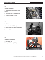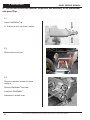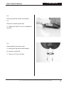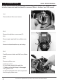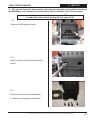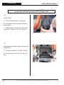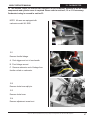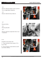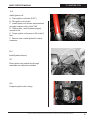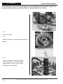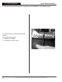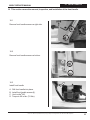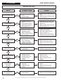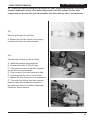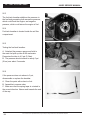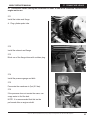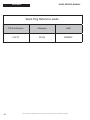
1
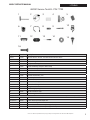
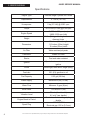
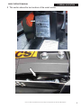
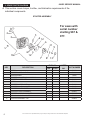
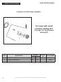
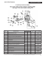
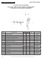
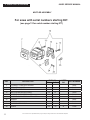
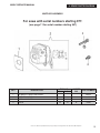
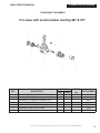
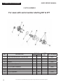
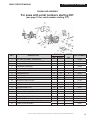
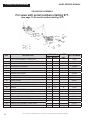
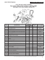
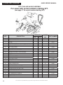
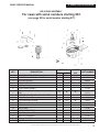
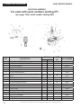
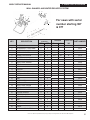
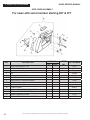
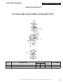
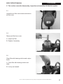
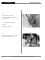
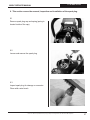
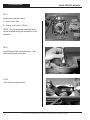
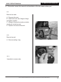
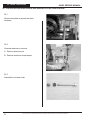
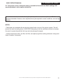
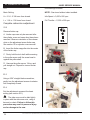
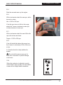
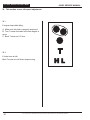
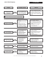
680GC
SERVICE MANUAL
i
© 2011 ICS- Blount Inc Specifications and pricing are subject to change without notice. P/N 525747 REV12Sep2012
680GC SERVICE MANUAL
TABLE OF CONTENTS
SECTION
SECTION TITLE
SERVICE MANUAL USE2
1
TOOLS3
2
SAW SPECIFICATIONS
4
3
SERIAL NUMBER LOCATION
5
4
SPARE PARTS DIAGRAM (TORQUE AND LOCTITE®)6
5
AIR INTAKE
25
6
SPARK PLUG
27
7
CLUTCH & RIM SPROCKET29
8
STARTER SYSTEM33
9
WALLWALKER®38
10
CYLINDER COVER
40
11
MUFFLER
43
12
CARBURETOR
47
13
CYLINDER & PISTON
49
14
WATER HOSE & CAP
58
15
IGNITION COIL60
16
FLYWHEEL62
17
BOTTOM GUARD
64
18
FRONT HANDLE
65
19
FUEL TANK66
20
CRANKCASE
67
21
BAR STUDS & BAR PAD
75
22
CHAIN TENSIONER
76
23
CARBURETOR TUNING
77
24
IDLE SPEED ADJUSTMENT80
25
TROUBLESHOOTING DIAGRAMS81
26
TROUBLESHOOTING: FUEL SYSTEM LEAKS83
27
TROUBLESHOOTING: CRANKCASE LEAKS
APPENDIX
1. SPARK PLUG REFERENCE GUIDE
PAGE NUMBER
© 2011 ICS- Blount Inc Specifications and pricing are subject to change without notice. P/N 525747 REV12Sep2012
85
86
1
SERVICE MANUAL USE
680GC SERVICE MANUAL
Service Manual Use
This manual contains all the technical information necessary for carrying out repairs on the
680GC saw. For safe, efficient work, it is of prime importance that the values indicated be
adhered to. Routine periodic maintenance is covered in the operator’s manual included with
each saw.
General Shop Rules
• Always use the right tools for the job, otherwise components may be damaged.
• Use a plastic dead blow mallet to separate parts attached solidly to each other.
• Mark mating parts as a reassembly reference.
• Keep component parts together as a group. Assemble screws and nuts into appropriate
subgroups.
• When reassembling, clean all parts carefully, lubricate moving parts and replace all oil seals,
o-rings, gaskets, washers and self-locking nuts.
• For best results, use only original ICS® replacement parts.
General Recommendations
• Some procedures in this manual require the use of special tools. A complete tool kit for the
680GC is available from ICS®.
• Detailed carburetor maintenance and overhaul information is available in Walbro’s
Diaphragm Carburetor Service Manual. Walbro can be contacted at http:\\www.walbro.com
or by calling 1.989.872.2131.
2
© 2011 ICS- Blount Inc Specifications and pricing are subject to change without notice. P/N 525747 REV12Sep2012
680GC SERVICE MANUAL
1. TOOLS
680GC Service Tool Kit - P/N 71700
1
2
3
4
5
6
7
8
9
10
11
12
13
14
15
16
Key #
Part No.
Description
Above
71700
Gas Saw Service Tool Kit, includes all items shown above
1
71521
Scrench 13-19 mm
2
71541
Pressure Gauge Bulb
3
71542
Coil/Flywheel Timing Shim
4
71543
Cylinder Assembly Clamps & Piston Stop
5
71544
Manifold Assembly Tool
6
71546
Shock Absorber Tool
7
71547
Spark Tester
8
71548
Flywheel Disassembly Tool
9
71550
Limiter Cap Puller
10
71565
Electronic Tachometer
11
71569
Induction Seal Flange with Screws
12
71570
Exhaust Seal Flange with Screws
13
71573
Tuning Screwdriver
14
73463
Main Bearing Spacing Tool
15
73425
Fuel Tank Pressure Cap
16
73462
Main Bearing Driver Tool
Items below are not included in P/N 71700, Gas Saw Service Tool Kit, but can be purchased separately
Not Shown
71734
Gasket Set
Not Shown
70249
14T Bar Nose Sprocket Repair Kit
Not Shown
71625
Carburetor Tuning Kit
Not Shown
505882
2-Stroke Oil, 25:1 Mix, 5.2 oz (158 ml) (6-Pack)
Not Shown
505883
2-Stroke Oil, 25:1 Mix, 5.2 oz (158 ml) (24-Pack)
© 2011 ICS- Blount Inc Specifications and pricing are subject to change without notice. P/N 525747 REV12Sep2012
3
680GC SERVICE MANUAL
2. SPECIFICATIONS
Specifications
Engine Type
2-stroke Single Cylinder Air Cooled
Displacement
4.7 cu-in (76.5 cc)
Horsepower
5 hp (3.7 kW) @ 9,500 rpm
Torque
36.3 in-lbs (4.1 Nm) @ 6,500 rpm
Engine Speed
Weight
Dimensions
Air Filter
Water resistant polyester
Carburetor
Walbro WJ122B
Starter
Dust and water resistant
Ignition
Special water resistant electronic
ignition
Clutch
Centrifugal, three shoe, single spring
Fuel ratio
25:1 (4%) gasoline-to-oil
Fuel Capacity
0.23 gal (.88 liter)
Water Supply
Minimum 20 psi (1.5 bar)
Water Flow
Minimum: 2 gpm (8 lpm)
Noise Level
101 dB at 3 ft (1m)
Vibration Level
Engine Break-in Period
Spark Plug
4
11,500 +/- 500 rpm (max)
2,800-3,200 rpm (idle)
21 lbs (9.5 kg) without guidebar and
diamond chain
18 inches (46cm) length
11.5 inches (29cm) height
10 inches (25cm) width
7.2 m/s2 (front handle)
8.5 m/s2 (rear handle)
One tank, without cutting, cycling
throttle
NGK BPMR8Y
Electrode gap .020 in (0.5 mm)
© 2011 ICS- Blount Inc Specifications and pricing are subject to change without notice. P/N 525747 REV12Sep2012
680GC SERVICE MANUAL
3. SERIAL # LOCATION
3 This section shows the two locations of the serial number.
© 2011 ICS- Blount Inc Specifications and pricing are subject to change without notice. P/N 525747 REV12Sep2012
5
680GC SERVICE MANUAL
4. SPARE PARTS DIAGRAM
4 This section covers torque, Loctite®, and lubrication requirements of the
individual components.
STARTER ASSEMBLY
2
5
3
6
12
For saws with
serial number
starting 967 &
977.
6
11
1
10
KEY
6
4
9
12
7
DESCRIPTION
8 13
TORQUE
Nm
in‑lbs.
4.0
X
1
Screw
2
Starter Rope Handle
530208
3
Starter Rope
73904
4
Starter Coil Spring & Housing
531103
5
Starter Case Plate
71451
6
Screw
505380
7
Starter Rope Pulley
528661
8
Starter Pulley Washer
73905
9
Starter Pulley Screw
10
Starter Cover Assembly
11
Starter Assembly Washer
530367
12
Spring Housing Washer
532026
13
Starter Assembly Cap
508853
5.9
35
LOCTITE®
PART NUMBER
242
52
X
© 2011 ICS- Blount Inc Specifications and pricing are subject to change without notice. P/N 525747 REV12Sep2012
73230
73907
528637
680GC SERVICE MANUAL
4. SPARE PARTS DIAGRAM
FLYWHEEL & STARTER PAWL ASSEMBLY
For saws with serial
numbers starting
967.
(see page 8 for serial
number starting 977)
KEY
DESCRIPTION
TORQUE
Nm
in‑lbs.
LOCTITE®
PART NUMBER
242
31
Flywheel Shroud
531109
45
Flywheel Assembly
6.9
61
528651
48
Nut
29.3
260
73891
51
Washer
73911
57
Washer
73912
71
Starter Pawl Assembly
509163
© 2011 ICS- Blount Inc Specifications and pricing are subject to change without notice. P/N 525747 REV12Sep2012
7
680GC SERVICE MANUAL
4. SPARE PARTS DIAGRAM
FLYWHEEL & STARTER PAWL ASSEMBLY
1
2
For saws with serial
numbers starting 977.
(see page 7 for serial number
starting 967)
3
KEY
8
DESCRIPTION
1
Flywheel Shroud
2
Flywheel Assembly Kit
3
Starter Pawl Assembly
TORQUE
Nm
in‑lbs.
LOCTITE®
PART NUMBER
242
531109
29.3
260
© 2011 ICS- Blount Inc Specifications and pricing are subject to change without notice. P/N 525747 REV12Sep2012
545963
509163
680GC SERVICE MANUAL
4. SPARE PARTS DIAGRAM
CYLINDER AND INTAKE ASSEMBLY
For saws with serial numbers starting 967.
(see page 10 for serial number starting 977)
KEY
DESCRIPTION
TORQUE
Nm
in‑lbs.
LOCTITE®
PART NUMBER
242
1
Intake Manifold Clamp
73867
2
Intake Manifold
73868
3
Wrist Pin Needle Bearing
73869
4
Complete Piston/Cylinder Assembly
71413
5
Cylinder Base Gasket Assembly
71412
6
Spark Plug
27.5
243
11
Cylinder Bolt
10.7
95
13
Carburetor Pulse Tube
73898
16
Carburetor, Walbro WJ-122B
528628
17
Intake Manifold Flange Screw
19
Carburetor Support Bracket
20
Decompression Valve
21
Intake Manifold Flange
73947
22
Intake Manifold
71735
23
Carburetor Spring
73888
24
Washer
73897
25
Screw & Washer
505469
26
Screw
73866
27
Screw Guide
517547
4.0
35
514770
X
X
73874
73901
73895
12.8
113
© 2011 ICS- Blount Inc Specifications and pricing are subject to change without notice. P/N 525747 REV12Sep2012
71642
9
4. SPARE PARTS DIAGRAM
680GC SERVICE MANUAL
CYLINDER AND INTAKE ASSEMBLY
For saws with serial numbers starting 977.
(see page 9 for serial number starting 967)
14
15
3
1
5
9
6
10
12
13
17
2
4
7
16
8
11
18
KEY
DESCRIPTION
TORQUE
Nm
in‑lbs.
LOCTITE®
PART NUMBER
242
1
Screw & Washer
505469
2
Washer
73897
3
Intake Manifold
71735
4
Intake Manifold Flange Screw
5
Intake Manifold Flange
4.0
35
X
73901
73947
6
Carburetor Spring
73888
7
Carburetor Pulse Tube
545877
8
Carburetor, Walbro WJ-122B
528628
9
Screw
10
Carburetor Support Bracket
73895
11
Screw Guide
517547
4.0
35
X
73866
12
Intake Manifold
73868
13
Intake Manifold Clamp
73867
14
Spark Plug
27.8
243
X
514770
15
Cylinder Bolt
10.7
95
X
73874
16
Complete Piston/Cylinder Assembly
548084
17
Gasket, Base
545874
18
Wrist Pin Needle Bearing
73869
10
© 2011 ICS- Blount Inc Specifications and pricing are subject to change without notice. P/N 525747 REV12Sep2012
4. SPARE PARTS DIAGRAM
680GC SERVICE MANUAL
MUFFLER ASSEMBLY
For saws with serial numbers starting 967.
(see page 12 for serial number starting 977)
KEY
11
DESCRIPTION
TORQUE
Nm
in‑lbs.
LOCTITE®
PART NUMBER
242
7
Cylinder to Muffler Gasket
73881
9
Serrated Washer
73327
10
Muffler Assembly
71411
12
Muffler Mounting Screw
14
Muffler Support Bracket
15
Muffler Support Bracket Screw
24
Washer
26
Screw
28
Muffler Deflector
29
Screw
9.8
87
73883
73884
8.8
78
4.0
35
73885
73897
x
73866
71481
4.0
35
x
© 2011 ICS- Blount Inc Specifications and pricing are subject to change without notice. P/N 525747 REV12Sep2012
71482
680GC SERVICE MANUAL
4. SPARE PARTS DIAGRAM
MUFFLER ASSEMBLY
For saws with serial numbers starting 977.
(see page 11 for serial number starting 967)
3
4
KEY
DESCRIPTION
TORQUE
Nm
in‑lbs.
1
Cylinder to Muffler Gasket
2
Muffler Assembly
3
Screw & WASHER
9.8
87
4
Screw
4.0
35
LOCTITE®
PART NUMBER
242
545875
545872
505469
x
© 2011 ICS- Blount Inc Specifications and pricing are subject to change without notice. P/N 525747 REV12Sep2012
73866
12
4. SPARE PARTS DIAGRAM
680GC SERVICE MANUAL
CRANKSHAFT ASSEMBLY
For saws with serial number starting 967 & 977
KEY
DESCRIPTION
TORQUE
Nm
in‑lbs.
LOCTITE®
PART NUMBER
242
1
Crankshaft Seal Flywheel Side
73877
2
Crankshaft Bearing
73209
3
Crankshaft Flywheel Woodruff Key
73878
4
Crankshaft Assembly
71410
5
Wrist Pin Needle Bearing
73869
6
Crankshaft Seal Clutch Side
73289
7
Crankshaft Bushing
71452
© 2011 ICS- Blount Inc Specifications and pricing are subject to change without notice. P/N 525747 REV12Sep2012
13
4. SPARE PARTS DIAGRAM
680GC SERVICE MANUAL
CLUTCH ASSEMBLY
For saws with serial number starting 967 & 977
KEY
DESCRIPTION
LOCTITE®
PART NUMBER
242
1
Outer Crankcase Seal, Clutch Side
73931
2
Outer Crankcase Seal Body
73949
3
Bolt
4
Washer
73285
5
Clutch Spacer Washer
73945
6
8T Rim Sprocket Kit
70949
7
Clutch Needle Bearing
73939
8
Clutch Drum Assembly
71520
9
Clutch Spacer Washer, Inside
73941
2.9
10
Clutch Assembly
11
Clutch Spring
14
TORQUE
Nm
in‑lbs.
33.3
26
295
© 2011 ICS- Blount Inc Specifications and pricing are subject to change without notice. P/N 525747 REV12Sep2012
73940
71419
73943
4. SPARE PARTS DIAGRAM
680GC SERVICE MANUAL
CRANKCASE ASSEMBLY
For saws with serial numbers starting 967.
(see page 16 for serial number starting 977)
KEY
1
2&5
DESCRIPTION
TORQUE
Nm
in‑lbs.
LOCTITE®
PART NUMBER
242
Fuel Line Grommet, Crankcase
73390
Crankcase Assembly, right & left
528653
3
Crankcase Dowel Pin
73281
4
Crankshaft Bearing
73209
7
Choke Lever Split Pin
73927
8
Crankcase Gasket
73934
9
Crankcase Bolt
10
Washer
73897
7.8
69
x
73930
11
Chain Guard
528657
12
Bar Mount Pad Spacer
71740
13
Cover Guard Mounting Bolt
7.8
69
x
73397
14
Screw
4.9
43
x
73379
15
Bar Mounting Stud
11.8
104
16
Screw
7.8
69
17
Bar Mount Pad Cover Plate
71738
18
Premium Tensioner Kit
73935
19
Tensioner Screw Retainer
73936
20
Choke Lever
530469
21
Crankcase Grommet, Right Side
531107
22
Choke Lever Bushing
73955
© 2011 ICS- Blount Inc Specifications and pricing are subject to change without notice. P/N 525747 REV12Sep2012
73933
73284
15
4. SPARE PARTS DIAGRAM
680GC SERVICE MANUAL
CRANKCASE ASSEMBLY
For saws with serial numbers starting 977.
(see page 15 for serial number starting 967)
4
17
14 11 16
7
4
5
19
21
KEY
18
20
DESCRIPTION
15
9
8
10
9
9 12
TORQUE
Nm
in‑lbs.
13
LOCTITE®
PART NUMBER
242
1
Fuel Line Grommet, Crankcase
73390
2
Crankcase Assembly, right & left
545967
3
Crankcase Dowel Pin
73281
4
Crankshaft Bearing
545969
5
Choke Lever Split Pin
73927
6
O-ring
71748
7
Crankcase Gasket
545968
8
Crankcase Bolt
7.8
69
x
73930
9
Washer
73897
10
Chain Guard
528657
11
Bar Mount Pad Spacer
71740
12
Cover Guard Mounting Bolt
7.8
69
x
73397
13
Screw
4.9
43
x
73379
14
Bar Mounting Stud
11.8
104
73933
15
Screw
7.8
69
73284
16
Bar Mount Pad Cover Plate
71738
17
Premium Tensioner Kit
73935
18
Tensioner Screw Retainer
73936
19
Choke Lever
530469
20
Crankcase Grommet, Right Side
531107
21
Choke Lever Bushing
73955
16
© 2011 ICS- Blount Inc Specifications and pricing are subject to change without notice. P/N 525747 REV12Sep2012
4. SPARE PARTS DIAGRAM
680GC SERVICE MANUAL
FUEL TANK AND HANDLE ASSEMBLY
For saws with serial numbers starting 967.
(see page 18 for serial number starting 977)
KEY
DESCRIPTION
TORQUE
Nm
in‑lbs.
LOCTITE®
PART NUMBER
242
1
Fuel Tank Assembly
528655
2
Rear Handle Half
531105
3
Screw
73976
4
Throttle Lever
530479
5
Fuel Cap Assembly, with Outer Seal Ring
530471
6
Fuel Cap O-Ring
73448
7
Fuel Filter
73459
8
Trigger Lockout Lever
532028
9
Trigger Lockout Lever Spring
73988
10
Washer
73897
11
Screw
73982
12
Shock Absorber
73980
13
Clip, Fuel Filter
71588
14
Fuel Line
73375
15
Shock Absorber, Rear Handle
71745
16
Bumper, Shock Absorber, Fuel Tank Top
73270
17
Front Handle Bolt
18
Front Handle
509205
19
Fuel Breather Complete
71748
20
Water Deflector, Bottom
71766
21
Breather Tube Body
71751
22
Breather Tube Elbow
71759
23
Fuel Breather, Remote
71761
24
Breather Tube Extension
71777
25
Tube Clamp
71760
7.8
69
x
© 2011 ICS- Blount Inc Specifications and pricing are subject to change without notice. P/N 525747 REV12Sep2012
73983
17
4. SPARE PARTS DIAGRAM
680GC SERVICE MANUAL
FUEL TANK AND HANDLE ASSEMBLY
For saws with serial numbers starting 977.
(see page 17 for serial number starting 967)
23
20 21
22
18
24
15
17
16
19
KEY
18
DESCRIPTION
TORQUE
Nm
in‑lbs.
LOCTITE®
PART NUMBER
242
1
Fuel Tank Assembly
528655
2
Rear Handle Half
531105
3
Screw
73976
4
Throttle Lever
530479
5
Fuel Cap Assembly, with Outer Seal Ring
530471
6
Fuel Cap O-Ring
73448
7
Fuel Filter
73459
8
Trigger Lockout Lever
532028
9
Trigger Lockout Lever Spring
73988
10
Washer
73897
11
Screw
73982
12
Shock Absorber
73980
13
Clip, Fuel Filter
71588
14
Fuel Line
73375
15
Bumper, Shock Absorber, Fuel Tank Top
16
Front Handle Bolt
17
Front Handle
545971
18
Fuel Breather Complete
71748
19
Water Deflector, Bottom
71766
20
Breather Tube Body
71751
21
Breather Tube Elbow
71759
22
Fuel Breather, Remote
71761
23
Breather Tube Extension
71777
24
Tube Clamp
71760
73270
7.8
69
x
© 2011 ICS- Blount Inc Specifications and pricing are subject to change without notice. P/N 525747 REV12Sep2012
73983
4. SPARE PARTS DIAGRAM
680GC SERVICE MANUAL
AIR INTAKE ASSEMBLY
For saws with serial numbers starting 967.
(see page 20 for serial number starting 977)
KEY
DESCRIPTION
TORQUE
Nm
in‑lbs.
LOCTITE®
PART NUMBER
242
1
Cylinder Cover Assembly
71754
2
Air Filter Canister, Polyester
71752
3
Air Filter Cover
530473
4
Filter Cover Screw
73992
5
Filter Support
73338
6
Filter Cover Gasket
71756
7
Screw, Cylinder Cover, Long, Socket
Head
8
Prefilter Plastic, Secondary Filter
73336
9
Air Filter Flange
71758
x
2.9
x
x
x
71771
10
Filter Support Screw
11
Filter Canister Gasket
73335
12
O-Ring
71472
13
Tube Clamp
71760
14
Compensator Tube
505382
15
Breather Grommet
19.7
26
174
73337
71763
16
Throttle Assembly
71750
17
O-Ring, Air Filter
73331
18
Washer
73897
© 2011 ICS- Blount Inc Specifications and pricing are subject to change without notice. P/N 525747 REV12Sep2012
19
4. SPARE PARTS DIAGRAM
680GC SERVICE MANUAL
AIR INTAKE ASSEMBLY
For saws with serial numbers starting 977.
(see page 19 for serial number starting 967)
KEY
DESCRIPTION
TORQUE
Nm
in‑lbs.
LOCTITE®
PART NUMBER
242
1
Cylinder Cover Assembly
545973
2
Air Filter Canister, Polyester
71752
3
Air Filter Cover
530473
4
Filter Cover Screw
73992
5
Filter Support
73338
6
Filter Cover Gasket
71756
7
Screw, Cylinder Cover, Long, Socket
Head
8
Prefilter Plastic, Secondary Filter
73336
9
Air Filter Flange
71758
x
x
x
71771
10
Filter Support Screw
11
Filter Canister Gasket
73335
12
O-Ring
71472
13
Tube Clamp
71760
14
Compensator Tube
505382
15
Breather Grommet
16
Throttle Assembly
71750
17
O-Ring, Air Filter
73331
18
Washer
73897
20
2.9
x
19.7
26
174
© 2011 ICS- Blount Inc Specifications and pricing are subject to change without notice. P/N 525747 REV12Sep2012
73337
71763
4. SPARE PARTS DIAGRAM
680GC SERVICE MANUAL
WALL WALKER® AND WATER DELIVERY SYSTEM
19
4
5
6
21
22
23
20
2
24
1
For saws with serial
number starting 967
& 977
25
27
26
3
7
15
18
16
14
12
9
16
9
8
KEY
10
11
DESCRIPTION
17
13
SERIAL NUMBER
STARTING
967
977
x
x
TORQUE
Nm
in‑lbs.
LOCTITE®
242
PART NUMBER
1
Guard Flap
2
WallWalker Lever Arm
x
x
71532
3
Guard Flap Clamp
x
x
71531
4
Screw & Washer
x
x
505469
5
Guard Flap Screw
x
x
6
Washer
x
x
73951
7
Guard Flap Spacer
x
x
71480
8
Water Hose Gasket
x
71469
9
Fitting
x
x
71467
10
Clip
x
x
545975
11
Ring Nut
x
x
71457
12
Water Hose O-Ring
x
x
71468
13
Water Shut-Off Valve
x
x
71458
14
Fitting
x
x
71454
15
Tube
x
x
71455
16
Hose Clamp
x
x
71465
17
Hose Hanger
x
x
71461
18
Water Hose Cover
x
x
71464
®
71534
4.8
19.7
43
x
174
71479
19
Water Hose Screw
x
x
20
Fitting
x
x
71453
21
Copper Washer
x
x
71456
22
Water Tank Cap
x
x
73923
23
Fuel Cap O-Ring
x
x
73448
24
Tube
x
x
71459
25
Fitting
x
x
71470
26
Fitting
x
x
71471
27
O-Ring
x
x
71472
28
Hose Hanger Button
x
x
71744
© 2011 ICS- Blount Inc Specifications and pricing are subject to change without notice. P/N 525747 REV12Sep2012
71463
21
4. SPARE PARTS DIAGRAM
680GC SERVICE MANUAL
SIDE COVER ASSEMBLY
For saws with serial number starting 967 & 977
KEY
DESCRIPTION
TORQUE
Nm
in‑lbs.
LOCTITE®
PART NUMBER
242
1
Side Cover Insert, Top
71534
2
Side Cover Nut
71532
3
Chain Cover Cap
71531
4
Nut
505469
5
WallWalker Side Arm
6
Washer
73951
7
WallWalker® Side Arm Screw
71480
8
Screw
71469
9
Side Cover Plate
71467
10
Lower Guard
545975
11
Side Cover Insert, Bottom Rear
71457
12
Side Cover Insert, Top Rear
71468
13
Rubber Bumper Cover
71458
14
Side Cover Assembly, Complete
71454
22
®
4.8
43
x
© 2011 ICS- Blount Inc Specifications and pricing are subject to change without notice. P/N 525747 REV12Sep2012
71479
4. SPARE PARTS DIAGRAM
680GC SERVICE MANUAL
CARBURETOR REPAIR KIT
For saws with serial number starting 967 & 977
KEY
DESCRIPTION
TORQUE
Nm
in‑lbs.
LOCTITE®
PART NUMBER
242
1
Carburetor, Walbro WJ-122b
528628
2
Carburetor Repair Kit
73996
© 2011 ICS- Blount Inc Specifications and pricing are subject to change without notice. P/N 525747 REV12Sep2012
23
680GC SERVICE MANUAL
This page intentionally left blank.
24
© 2011 ICS- Blount Inc Specifications and pricing are subject to change without notice. P/N 525747 REV12Sep2012
680GC SERVICE MANUAL
5. AIR INTAKE
5. This section covers the disassembly, inspection and assembly air induction system.
5.1
Loosen the air filter cover screws and remove
air filter cover.
5.2
Remove air filter from cover.
A. Inspect air filter
B. Replace if necessary
5.3
Clean filter with cleaning solution and a nylon
brush.
A. Clean filter with cleaning solution and
water.
B. Let dry and reinstall.
© 2011 ICS- Blount Inc Specifications and pricing are subject to change without notice. P/N 525747 REV12Sep2012
25
5. AIR INTAKE
680GC SERVICE MANUAL
5.4
Inspect air filter cover gasket.
A. Replace if permanently depressed or
hard, due to slurry.
5.5 Inspect filter canister gasket.
A. Clean
B. Replace if necessary
5.6
Check air filter mount screws and lightly
secure them if they are loose.
26
© 2011 ICS- Blount Inc Specifications and pricing are subject to change without notice. P/N 525747 REV12Sep2012
680GC SERVICE MANUAL
6. SPARK PLUG
6. This section covers the removal, inspection and installation of the spark plug.
6.1
Remove spark plug cap and spring (spring is
located inside of the cap).
6.2
Loosen and remove the spark plug.
6.3
Inspect spark plug for damage or corrosion.
Clean with a wire brush.
© 2011 ICS- Blount Inc Specifications and pricing are subject to change without notice. P/N 525747 REV12Sep2012
27
6. SPARK PLUG
680GC SERVICE MANUAL
6.4
Gap if necessary to 0.02" (0.5mm).
NOTE:
If the spark plug must be replaced, refer to
the spark plug reference guide at the end of
this manual to select the correct replacement
plug.
6.5
Assemble in the reverse order.
Make sure the plug boot is seated completely.
28
© 2011 ICS- Blount Inc Specifications and pricing are subject to change without notice. P/N 525747 REV12Sep2012
680GC SERVICE MANUAL
7. CLUTCH & RIM SPROCKET
7. This section covers clutch removal, rim sprocket removal, inspection and assembly.
Refer to sections 5 and 6 if needed.
7.1
Insert piston stop tool into spark plug hole.
7.2
Pull starter handle until piston stops against
tool.
7.3
Remove clutch
Left hand threads - rotate
clockwise to loosen.
CAUTION
NOTE: If an impact wrench is available steps
7.1 and 7.2 do not need to be performed.
© 2011 ICS- Blount Inc Specifications and pricing are subject to change without notice. P/N 525747 REV12Sep2012
29
7. CLUTCH & RIM SPROCKET
680GC SERVICE MANUAL
7.4
Remove all drive components.
7.5
Inspect the clutch shoes for wear.
A. Replace if the shoe has less than 0.04" (1
mm) of material, as shown.
7.6
Inspect spring for cracks.
30
© 2011 ICS- Blount Inc Specifications and pricing are subject to change without notice. P/N 525747 REV12Sep2012
680GC SERVICE MANUAL
7. CLUTCH & RIM SPROCKET
7.7
Assemble clutch shoes as shown.
7.8
Finish installation of clutch shoe as shown.
7.9
Inspect the rim sprocket for wear.
A. Replace if the rim sprocket teeth are worn
to points, as shown on right.
© 2011 ICS- Blount Inc Specifications and pricing are subject to change without notice. P/N 525747 REV12Sep2012
31
7. CLUTCH & RIM SPROCKET
680GC SERVICE MANUAL
7.10
Clean and Assemble.
A. Clean all parts in solvent.
B. Grease clutch cup bearing with a
waterproof grease.
C. Assemble clutch spacer washer, bearing,
clutch cup with rim sprocket, and inside
clutch spacer washer.
7.11
Install clutch.
Torque to 295 in-lbs (33.3 Nm).
CAUTION
32
Left hand threads.
© 2011 ICS- Blount Inc Specifications and pricing are subject to change without notice. P/N 525747 REV12Sep2012
680GC SERVICE MANUAL
8. STARTER
8. This section covers the removal of the starter cover, replacement of the starter rope, and
replacement of the recoil spring.
8.1
Remove starter cover screws (4).
8.2
Remove starter cover assembly from saw.
8.3
Remove starter cord shield screws.
8.4
Relieve spring tension.
A. Pull 4-6" (10-15 cm) of rope out.
B. Line rope up with notch on pulley.
C. Slowly rotate pulley counter-clockwise
until spring pressure is released. Use thumb
as brake.
8.5
Remove starter pulley screw and washer.
NOTE: Hold starter cover firmly.
© 2011 ICS- Blount Inc Specifications and pricing are subject to change without notice. P/N 525747 REV12Sep2012
33
8. STARTER
680GC SERVICE MANUAL
8.6
Remove starter pulley.
8.7
Inspect coil spring.
A. Replace if spring hook is damaged.
Attemping to re-bend the spring hook may
cause the hook to break off.
B. Carefully remove coil spring and housing
to prevent spring from unwinding.
8.8 Lubricate with lightweight oil.
8.9 Replace parts carefully.
34
© 2011 ICS- Blount Inc Specifications and pricing are subject to change without notice. P/N 525747 REV12Sep2012
680GC SERVICE MANUAL
8. STARTER
8.10
Inspect pulley spring catch.
A. Clean with cleaning solution.
B. Replace if worn or broken.
8.11
Install starter rope and tie knot.
8.12
Install pulley.
A. Wind rope onto pulley clockwise leaving
4-6" (10-15 cm) out.
B. Make sure that the pulley spring catch is
in the spring hook.
8.13
Install center screw, spacer and washer.
A. Use Loctite® .242.
B. Torque to 26 in-lbs (2.9 Nm).
© 2011 ICS- Blount Inc Specifications and pricing are subject to change without notice. P/N 525747 REV12Sep2012
35
8. STARTER
680GC SERVICE MANUAL
8.14
Wind the recoil spring.
A. Line rope up with notch on pulley.
B. Rotate the pulley with the rope clockwise
5 times.
C. Untangle rope and release.
8.15
Assemble starter cord shield.
8.16
Remove starter pawl screws, pawls, spring
and plain washer.
NOTE: Piston stop tool may be required to
remove the starter pawl screws.
8.17
Inspect and clean pawl components.
A. Inspect the components. Replace if
necessary.
B. Clean the components with a brush and
solvent.
36
© 2011 ICS- Blount Inc Specifications and pricing are subject to change without notice. P/N 525747 REV12Sep2012
680GC SERVICE MANUAL
8. STARTER
8.18
Assemble components
A. Make sure the spring is in the correct
position.
B. Use Loctite® 242 on the pawl screws.
C. Torque to 60 in-lbs. (6.8 Nm).
8.19
Install starter cover.
A. Pull out cord 4-6" (10-15cm).
B. Slowly release while placing cover to allow
pawls to engage.
8.20
Install starter cover screws.
A. Use Loctite® 242.
B. Torque to 60 in-lbs. (6.8 Nm).
© 2011 ICS- Blount Inc Specifications and pricing are subject to change without notice. P/N 525747 REV12Sep2012
37
9. WALLWALKER
680GC SERVICE MANUAL
9. This section covers the removal, inspection and assembly of the WallWalker ®
and guard flap.
9.1
Inspect WallWalker ® tip.
A. If the tip is worn, as shown, replace.
9.2
Remove bar mount pad.
9.3
Remove crankcase screws and wave
washers.
Remove WallWalker ® from saw.
Install new WallWalker ®.
Assemble in reverse order.
38
© 2011 ICS- Blount Inc Specifications and pricing are subject to change without notice. P/N 525747 REV12Sep2012
680GC SERVICE MANUAL
9. WALLWALKER
9.4
Remove guard flap screws and washers.
9.5
Remove and inspect guard flap.
A. Replace the flap if it is torn or damaged in
any way.
9.6
Reassemble in the reverse order.
A. Install guard flap screws and washers.
B. Use blue Loctite® 242.
C. Torque to 43 in-lbs. (4.8 Nm).
© 2011 ICS- Blount Inc Specifications and pricing are subject to change without notice. P/N 525747 REV12Sep2012
39
10. CYLINDER COVER
680GC SERVICE MANUAL
10 This section covers the disassembly and assembly of the cylinder cover. Removal of the
air intake components and front handle is necessary. Refer to sections 1 and 14 if needed.
10.1
Remove the air filter mount screws.
10.2
Remove the cylinder cover screws (3).
10.3
Remove spark plug lead from cylinder cover.
10.4
Remove fuel tank breather cap and clamp.
10.5
Partially remove intake manifold from cylinder
cover.
10.6
Remove cylinder cover.
A. Pull up on front.
B. Push intake manifold through hole.
C. Make sure throttle linkage is disengaged
from cylinder cover.
D. Guide fuel breather tube and compensator
tube through cylinder cover.
40
© 2011 ICS- Blount Inc Specifications and pricing are subject to change without notice. P/N 525747 REV12Sep2012
680GC SERVICE MANUAL
10. CYLINDER COVER
10.7
Remove stop switch leads.
10.8
Inspect cylinder cover for damage.
A. Replace if necessary.
10.9
Check cylinder cover water seal and filter
cover gasket are in place and in good
condition.
A. Replace if necessary.
10.10
Reassemble stop switch leads.
screw boot
10.11
Make sure carburetor screw boot is in place.
10.12
Lubricate compensating tube and fuel tank
breather tube with soapy water, guide through
cylinder cover (install compensating tube
first).
NOTE:
Be careful as to not pull tubes away from
their point of connection. Approximately 3/4"
2 cm) of tube should protrude from cylinder
cover.
© 2011 ICS- Blount Inc Specifications and pricing are subject to change without notice. P/N 525747 REV12Sep2012
41
10. CYLINDER COVER
680GC SERVICE MANUAL
10.13
Install cylinder cover.
A. Pull spark plug lead into slot in cylinder
cover.
B. Align throttle linkage with cylinder cover
and crankcase.
C. Push the cylinder cover down on the
crankcase, guide intake manifold into cylinder
cover.
D. Install the cylinder cover screws. Use
Loctite® 242. Torque to 35 in-lbs. (4.0 Nm).
E. Install fuel tank breather and clamp.
10.14
Install air filter mount.
A. Guide carburetor compensating tube
through air filter mount. Make sure manifold
sits flat over lip on cylinder cover.
B. Install air filter mount screws (3) using
Loctite® 242.
C. Torque to 43 in-lbs (4.9 Nm.)
10.15
Install air filters and cover.
A.
B.
C.
D.
42
Install pre-filter.
Install clean air filter.
Install air filter flange and tighten.
Install air filter cover and tighten.
© 2011 ICS- Blount Inc Specifications and pricing are subject to change without notice. P/N 525747 REV12Sep2012
680GC SERVICE MANUAL
11. MUFFLER
11. This section covers the disassembly, inspection, and assembly of the muffler. Removal of
the WallWalker ® and cylinder cover is necessary. Refer to sections 7 and 10 if necessary.
11.1
For saws with serial number starting 967,
for saws with serial number starting 977 see pages 45/46
Remove muffler support screws.
11.2
Remove muffler screws and serrated
washers located inside the muffler.
11.3
Remove muffler and heat shield gasket.
A. Replace any damaged components.
© 2011 ICS- Blount Inc Specifications and pricing are subject to change without notice. P/N 525747 REV12Sep2012
43
11. MUFFLER
680GC SERVICE MANUAL
For saws with serial number starting 967,
for saws with serial number starting 977 see pages 45/46
11.4
Install muffler.
A. Insert muffler screws and serrated washer
(2) into muffler.
B. Hold muffler screws in place with heat
shield gasket.
C. Thread muffler screws into cylinder,
torque to 78 in-lbs. (8.8 Nm).
11.5
Install muffler support.
A. Install top (3) muffler support screws and
serrated washer finger tight.
B. Install bottom (2) muffler support screws
with Loctite®242.
C. Torque top screws to 78 in-lbs. (8.8 Nm).
D. Torque bottom screws to 52 in-lbs. (5.8
Nm).
44
© 2011 ICS- Blount Inc Specifications and pricing are subject to change without notice. P/N 525747 REV12Sep2012
680GC SERVICE MANUAL
11. MUFFLER
11. This section covers the disassembly, inspection, and assembly of the muffler. Removal of
the WallWalker ® and cylinder cover is necessary. Refer to sections 7 and 10 if necessary.
For saws with serial number starting 977,
for saws with serial number starting 967 see pages 43/44
11.1
Remove muffler support screws.
11.2
Remove muffler screws located inside the
muffler.
11.3
Remove muffler and heat shield gasket.
A. Replace any damaged components.
© 2011 ICS- Blount Inc Specifications and pricing are subject to change without notice. P/N 525747 REV12Sep2012
45
11. MUFFLER
680GC SERVICE MANUAL
For saws with serial number starting 977,
for saws with serial number starting 967 see pages 43/44
11.4
Install muffler.
A. Insert muffler screws (2) into muffler.
B. Hold muffler screws in place with heat
shield gasket.
C. Thread muffler screws into cylinder with
Loctite®242. Torque to 78 in-lbs. (8.8 Nm).
11.5
Install bottom (2) muffler support screws with
Loctite®242.
A. Torque top screws to 78 in-lbs. (8.8 Nm).
B. Torque bottom screws to 52 in-lbs. (5.8
Nm).
46
© 2011 ICS- Blount Inc Specifications and pricing are subject to change without notice. P/N 525747 REV12Sep2012
680GC SERVICE MANUAL
12. CARBURETOR
12. This section covers the removal and insallation of the carburetor. Removal of the air intake
components and cylinder cover is required. Please refer to section 5, 10 or 11 if necessary.
Carburetor tuning is covered in section 23.
NOTE: All saws are equipped with
carburetor model WJ-122B.
12.1
Remove throttle linkage.
A. Push trigger end out of rear handle.
B. Pivot linkage around.
C. Remove carburetor end of linkage from
throttle rod tab on carburetor.
12.2
Remove choke lever split pin.
12.3
Remove choke lever.
12.4
Remove adjustment screw boot.
© 2011 ICS- Blount Inc Specifications and pricing are subject to change without notice. P/N 525747 REV12Sep2012
47
12. CARBURETOR
680GC SERVICE MANUAL
12.5
Remove carburetor support screw (1) with #4
Torx or straight blade screwdriver.
12.6
Remove carburetor body screws (2).
12.7
Remove fuel line.
12.8
Remove pulse tube.
12.9
Remove carburetor compensator tube on top
of carburetor.
12.10
Assemble in the reverse order.
A. Torque carburetor body screws to 43 inlbs. (4.9 Nm).
B. Torque supporter screw with blue Loctite®
to 43 in-lbs. (4.9 Nm).
48
© 2011 ICS- Blount Inc Specifications and pricing are subject to change without notice. P/N 525747 REV12Sep2012
680GC SERVICE MANUAL
13. CYLINDER & PISTON
13. This section covers the removal, inspection and assembly of the cylinder, piston and
related components. Removal of several component groups is required. Refer to sections 5, 6,
10 and 12 if necessary.
NOTE:
When replacing the 680GC cylinder and
piston it is necessary to tune the carburetor
prior to returning the saw to service. See
section 23.
13.1
Remove carburetor base screws.
A. Remove carburetor base from rear
manifold. Push rear manifold through
carburetor base while holding carburetor
base.
B. Remove carburetor base from pulse tube.
13.2
Remove pulse tube and protective spring
from cylinder base.
© 2011 ICS- Blount Inc Specifications and pricing are subject to change without notice. P/N 525747 REV12Sep2012
49
13. CYLINDER & PISTON
680GC SERVICE MANUAL
13.3
Remove rear manifold clamp.
13.4
Remove rear manifold from cylinder.
A. Inspect for holes and tears in the
manifold, replace if damaged.
13.5
Remove cylinder screws (4) and wave
washers.
13.6
Remove cylinder.
A. Remove cylinder gasket and clean
crankcase mating surface.
50
© 2011 ICS- Blount Inc Specifications and pricing are subject to change without notice. P/N 525747 REV12Sep2012
680GC SERVICE MANUAL
13. CYLINDER & PISTON
13.7
Remove wrist pin retaining clips (2)
13.8
Press wrist pin out with an 8mm deep socket.
13.9
Remove piston and inspect. Replace if
damaged.
13.10
Remove wrist pin bearing.
© 2011 ICS- Blount Inc Specifications and pricing are subject to change without notice. P/N 525747 REV12Sep2012
51
13. CYLINDER & PISTON
680GC SERVICE MANUAL
13.11
Cylinder gasket.
A. Oil gasket with ICS® 2-stroke engine oil.
B. Install and align holes and notch.
13.12
Install wrist pin bearing in rod.
A. Oil bearing with ICS® 2-stroke engine oil.
13.13
Install rings.
Install bottom ring first. Installing the bottom
ring over the top ring may cause the ring to
break.
52
© 2011 ICS- Blount Inc Specifications and pricing are subject to change without notice. P/N 525747 REV12Sep2012
680GC SERVICE MANUAL
13. CYLINDER & PISTON
13.14
Ring orientation.
13.15
Install (1) wrist pin retaining clip.
13.16
Make sure wrist pin retaining clip is in the
proper orientation.
Improper installation may result in
serious engine damage.
© 2011 ICS- Blount Inc Specifications and pricing are subject to change without notice. P/N 525747 REV12Sep2012
53
13. CYLINDER & PISTON
680GC SERVICE MANUAL
13.17
Partially install wrist pin.
13.18
Align piston in correct orientation.
EXHAUST
INTAKE
13.19
A.
B.
C.
D.
Oil piston with ICS® 2-stroke oil.
Align wrist pin with wrist pin bearing.
Complete wrist pin installation.
Install second wrist pin retaining clip.
Make sure wrist pin retaining clip is in
the proper orientation (see 13.16).
54
© 2011 ICS- Blount Inc Specifications and pricing are subject to change without notice. P/N 525747 REV12Sep2012
680GC SERVICE MANUAL
13. CYLINDER & PISTON
13.20
Install cylinder.
A. Lubricate cylinder bore with ICS® 2-stroke
oil.
B. Compress rings with ring compression
tool.
C. Slide cylinder onto piston, pushing ring
compression tool down.
13.21
Install cylinder.
A. Remove ring compression tool.
B. Slide cylinder down piston and into
crankcase.
C. Align cylinder bolt holes with crankcase.
13.22
Install 4 cylinder screws and washers.
A. Use Loctite®242.
B. Torque bolts to 95 in-lbs. (10.7 Nm).
© 2011 ICS- Blount Inc Specifications and pricing are subject to change without notice. P/N 525747 REV12Sep2012
55
13. CYLINDER & PISTON
680GC SERVICE MANUAL
13.23
Install rear manifold.
A. Lubricate rear manifold with ICS® 2-stroke
oil.
B. Push rear manifold onto cylinder intake.
C. Align rear manifold seam with cylinder
and crankcase seam.
13.24
Install rear manifold clamp.
A. Torque to 11 in-lbs. (1.2 Nm).
Do not over tighten, damage to rear
manifold may cause engine damage.
13.25
Install the pulse tube onto cylinder barb.
13.26
Install protective spring onto pulse tube.
56
© 2011 ICS- Blount Inc Specifications and pricing are subject to change without notice. P/N 525747 REV12Sep2012
680GC SERVICE MANUAL
13. CYLINDER & PISTON
13.27
Install carburetor base.
A. Slip pulse tube into and through
carburetor base.
B. Slip rear manifold into and through
carburetor base.
C. Make sure rear manifold lip is flat.
13.28
Install carburetor base screws.
A. Use Loctite® 242 on (3) screws without
ground wire.
B. Make sure to include stop switch wire
(installed on left rear screw).
C. Torque to 35 in-lbs. (4 Nm).
© 2011 ICS- Blount Inc Specifications and pricing are subject to change without notice. P/N 525747 REV12Sep2012
57
14. WATER HOSE
680GC SERVICE MANUAL
14. This section covers water hose and water tank cap.
14.1
Loosen hose clamp screw.
14.2
Remove water connection from hose.
14.3
Remove hose from hose hanger.
14.4
Remove water hose connector.
14.5
Unscrew water tank cap from saw (7/8
wrench).
58
© 2011 ICS- Blount Inc Specifications and pricing are subject to change without notice. P/N 525747 REV12Sep2012
680GC SERVICE MANUAL
14. WATER HOSE
14.6
Release water tank cap from water tank tube.
A. Depress orange fitting (as shown) to
release water tank tube.
14.7
Assemble in reverse order.
© 2011 ICS- Blount Inc Specifications and pricing are subject to change without notice. P/N 525747 REV12Sep2012
59
15. IGNITION COIL
680GC SERVICE MANUAL
15. This section covers the removal, inspection, and installation of the ignition coil. Removal
of the starter is required. Refer to section 8 if necessary.
15.1
Remove starter flywheel shroud by
unhooking wires.
15.2
Remove ignition coil screws, wave washers
and plain washers.
15.3
Remove ignition coil.
15.4
Inspect.
A. Look for cracks/missing insulation.
B. Clean flywheel magnets and coil if rusty.
60
© 2011 ICS- Blount Inc Specifications and pricing are subject to change without notice. P/N 525747 REV12Sep2012
680GC SERVICE MANUAL
15. IGNITION COIL
15.5
Install ignition coil.
A. Place ignition coil shim (0.012")
B. Set ignition coil in place.
C. Install ignition coil screws, wave washers,
and plain washers with Loctite® 242.
D. Holding shim, rotate flywheel magnet
around to coil.
E. Torque ignition coil screws to 26 in-lbs.(3
Nm).
F. Remove shim, rotate flywheel to check
clearance.
15.6
Install flywheel shroud.
15.7
Route ignition stop switch wire through
crankcase into carburetor chamber.
15.8
Complete ignition wire routing.
© 2011 ICS- Blount Inc Specifications and pricing are subject to change without notice. P/N 525747 REV12Sep2012
61
16. FLYWHEEL
680GC SERVICE MANUAL
16. This section covers the removal, inspection, and installation of the flywheel. Removal of
the starter and spark plug is requried. Refer to sections 6 and 8 if necessary.
16.1
Insert piston stop.
16.2
Remove flywheel nut, wave washer, and plain
washer.
16.3
Screw on flywheel removal tool finger
tight. Unscrew tool 1 1/2 turns leaving
approximately 1/8 inch (5 mm) space
between tool and flywheel.
62
© 2011 ICS- Blount Inc Specifications and pricing are subject to change without notice. P/N 525747 REV12Sep2012
680GC SERVICE MANUAL
16. FLYWHEEL
16.4
Using pliers, hold saw up by magnet
counterweight.
16.5
Strike flywheel removal tool with a ball peen
hammer. The flywheel should release from
crankshaft.
16.6
Inspect and clean flywheel. Replace if any of
the fins are broken.
16.7
Inspect woodruff key.
16.8
Install flywheel, plain washer, wave washer,
and flywheel nut.
A. Torque nut to 260 in-lbs (29.3 Nm.)
© 2011 ICS- Blount Inc Specifications and pricing are subject to change without notice. P/N 525747 REV12Sep2012
63
17. BOTTOM GUARD
680GC SERVICE MANUAL
17. This section covers the removal, inspection, and installation of the bottom guard.
A. Remove bottom guard screws and split
washers.
B. Inspect bottom guard.
C. Replace if damaged.
D. Assemble in reverse order.
64
© 2011 ICS- Blount Inc Specifications and pricing are subject to change without notice. P/N 525747 REV12Sep2012
680GC SERVICE MANUAL
18. FRONT HANDLE
18. This section covers the removal, inspection, and installation of the front handle.
18.1
Remove front handle screws on right side.
18.2
Remove front handle screws on bottom.
18.3
Install front handle
A.
B.
C.
D.
Roll front handle into place.
Install front handle screws (4).
Use Loctite®242.
Torque to 69 in-lbs. (7.8 Nm).
© 2011 ICS- Blount Inc Specifications and pricing are subject to change without notice. P/N 525747 REV12Sep2012
65
19. FUEL TANK
680GC SERVICE MANUAL
19. This section covers the disassembly, inspection, and assembly of the vibration isolators,
fuel tank and rear handle.
19.1
Remove vibration isolator screws and wave
washers on clutch side of saw.
19.2
Remove vibration isolator screws and wave
washers on flywheel side of saw.
66
© 2011 ICS- Blount Inc Specifications and pricing are subject to change without notice. P/N 525747 REV12Sep2012
680GC SERVICE MANUAL
19. FUEL TANK
19.3
Separate crankcase and fuel tank.
NOTE: Saws have a rubber water deflector
connected to the (2) bottom vibration isolators
on the clutch side (circled).
19.4
Remove vibration isolators from fuel tank (6)
if necessary.
* Shock absorber tool p/n #71546 should be
used for removal and installation.
19.5
Assemble in reverse order.
NOTE: During assembly be careful to avoid
kinking the fuel line.
© 2011 ICS- Blount Inc Specifications and pricing are subject to change without notice. P/N 525747 REV12Sep2012
67
20. CRANKCASE
680GC SERVICE MANUAL
20. This section covers the removal, inspection and assembly of the crankcase seals and
crankshaft bearings.
20.1
Remove outer crankshaft seal housing
screws and wave washers.
20.2
Remove crankcase bolts.
20.3
Heat the flywheel side crankcase with heat
gun for 5 minutes, approximately 150° F
(65.5° C).
68
© 2011 ICS- Blount Inc Specifications and pricing are subject to change without notice. P/N 525747 REV12Sep2012
680GC SERVICE MANUAL
20. CRANKCASE
20.4
Remove the flywheel side crankcase — tap
crankshaft with plastic mallet.
A. Suspend above work surface.
B. Tap with mallet.
NOTE: A nut should always be placed on a
threaded shaft when pounding or pressing on it.
20.5
Remove the flywheel side crankcase seal with
1/2" (13 mm) socket.
20.6
Heat the clutch side crankcase with heat gun to
150°F (65.5°) C.
© 2011 ICS- Blount Inc Specifications and pricing are subject to change without notice. P/N 525747 REV12Sep2012
69
20. CRANKCASE
680GC SERVICE MANUAL
20.7
Remove crankshaft from the clutch-side
crankcase tap crankshaft with a plastic
mallet.
A. Suspend above work surface.
B. Tap with plastic mallet.
20.8
Remove the bearing from the flywheel side of
crankshaft.
20.9
Remove the bearing, seal, and bushing from
the clutch side of crankshaft.
70
© 2011 ICS- Blount Inc Specifications and pricing are subject to change without notice. P/N 525747 REV12Sep2012
680GC SERVICE MANUAL
20. CRANKCASE
20.10
Clean mating crankcase faces.
20.11
Heat crankcase halves to 150° F (65.5°) C.
20.12
Install bearing into crankcase halves.
20.13
Tap with bearing driver and mallet.
20.14
Repeat with other half.
© 2011 ICS- Blount Inc Specifications and pricing are subject to change without notice. P/N 525747 REV12Sep2012
71
20. CRANKCASE
680GC SERVICE MANUAL
20.15
Install crankshaft into clutch side of case.
20.16
Place clutch side crankcase seal on
crankshaft.
A. Tap lightly with bearing driver and mallet.
20.17
Coat crankcase gasket with ICS® 2-stroke
engine oil.
72
© 2011 ICS- Blount Inc Specifications and pricing are subject to change without notice. P/N 525747 REV12Sep2012
680GC SERVICE MANUAL
20. CRANKCASE
20.18
Align crankcase gasket on flywheel side
crankcase pins.
20.19
Place crankcase halves together and align
crankcase pins.
20.20
Assemble crankcase halves — tap with
bearing driver and mallet.
© 2011 ICS- Blount Inc Specifications and pricing are subject to change without notice. P/N 525747 REV12Sep2012
73
20. CRANKCASE
680GC SERVICE MANUAL
20.21
Install main crankcase bolts.
A. Use Loctite® 242.
B. Torque to 69 in-lbs. (7.8 Nm.)
NOTE: The (3) remaining crankcase bolts
will be installed during the completion of the
assembly.
20.22
Install flywheel side crankcase seal — tap
with bearing driver and mallet.
20.23
Trim crankcase gasket flush.
74
© 2011 ICS- Blount Inc Specifications and pricing are subject to change without notice. P/N 525747 REV12Sep2012
680GC SERVICE MANUAL
21. BAR STUDS & BAR PAD
21. This section covers the removal and installation of the bar studs and bar pad.
21.1
Remove bar studs.
A. Remove side cover.
B. Install side cover nuts, flange to flange
and tighten together.
C. Attempt to remove the inside nut which
should pull out the bar stud.
D. Repeat on the second bar stud.
21.2
Remove bar pad.
A. Remove sealing o-ring.
21.3
Assemble in reverse order.
© 2011 ICS- Blount Inc Specifications and pricing are subject to change without notice. P/N 525747 REV12Sep2012
75
22. CHAIN TENSIONER
680GC SERVICE MANUAL
22. This section covers the removal and installation of the chain tensioner.
22.1
Remove bar plate to expose the chain
tensioner.
22.2
Unscrew tensioner to remove.
A. Remove tensioner pin.
B. Remove tensioner screw keeper.
22.3
Assemble in reverse order.
76
© 2011 ICS- Blount Inc Specifications and pricing are subject to change without notice. P/N 525747 REV12Sep2012
680GC SERVICE MANUAL
23. CARBURETOR TUNING
23. This section covers carburetor tuning. Included in this section are basic settings, idle
speed adjustment, and complete adjustment.
The carburetor has been set at the factory for optimal performance and compliance to EPA Phase II
emissions standards. However, minor adjustments may be required in certain conditions, such as high
elevation.
NOTES:
• These saws are equipped with an electronic speed limiter, as part of the ignition system. This will
prevent the saw from going above 12,000 RPM. Attempting to set the carburetor mixture to increase
the speed or power beyond this limit may seriously damage the engine.
• Always check the air filter, pre filter, fuel filter, and spark plug before making carburetor tunings and
clean or replace if necessary.
© 2011 ICS- Blount Inc Specifications and pricing are subject to change without notice. P/N 525747 REV12Sep2012
77
23. CARBURETOR TUNING
680GC SERVICE MANUAL
23.1
RPM settings for saws.
Basic Setting:
NOTE: Saw tuned without chain installed.
H = 2 1/4 - 2 3/8 turns from closed.
Idle Speed = 3,000 ± 200 rpm
L = 1 1/4 to 1 3/8 turns from closed.
Full Throttle = 11,500 ± 500 rpm
Complete carburetor readjustment.
23.2
Remove limiter cap.
A. Limiter caps can only be removed after
the cylinder cover and screw boot have been
removed. Observe orientation of the release
slots on the adjustment screw limiter cap.
See section 10 for cylinder cover removal.
B. Insert the limiter cap puller into the center
of the limiter cap.
A
C. Firmly hold the tool shaft while screwing
in the puller screw until the screw head is
against the puller shaft.
D. Unscrew the puller screw, 1/4 turn and
pull straight out. Repeat for second limiter
cap.
B, C, D
23.3
Using a 5/64" straight blade screwdriver,
gently turn the adjustment screws clockwise
until completely closed.
23.4
Set the adjustment screws at the basic
setting (see section 23.1).
The side cover must be held tightly
in place with the side cover nuts, using a
bar and no chain. Failure to follow this
procedure may result in personal injury
and or damage to the saw.
78
© 2011 ICS- Blount Inc Specifications and pricing are subject to change without notice. P/N 525747 REV12Sep2012
680GC SERVICE MANUAL
23. CARBURETOR TUNING
23.5
Start the saw and warm up the engine.
23.6
With a tachometer check the saw rpm, with a
bar and no chain.
Idle = 3,000 ± 200 rpm.
If the idle rpm does not fall into this range,
adjust the T screw, clockwise to raise rpm,
counterclockwise to lower rpm.
23.7
With a tachometer check the saw full throttle
rpm, with no bar and chain:
Target:= 11,500 ± 500 rpm
23.8
If the full throttle falls below this range, turn
the H screw in (clockwise) 1/16th of a turn at
a time.
A. Pulse the throttle to help stablize the
system.
Do not hold the saw at max rpm for
more than 5 seconds or cylinder damage
could occur.
23.9
When the carburetor is adjusted correctly,
set the limiter caps securely onto the needle
screws with a straight blade screwdriver.
© 2011 ICS- Blount Inc Specifications and pricing are subject to change without notice. P/N 525747 REV12Sep2012
79
24. IDLE SPEED ADJUSTMENT
680GC SERVICE MANUAL
24. This section covers idle speed adjustment.
24.1
If engine stops while idling:
A. Make sure the chain is properly tensioned.
B. Turn T screw clockwise until chain begins to
move.
C. Back T screw out 1/2 turn.
24.2
If chain turns at idle.
Back T screw out until chain stops moving.
80
© 2011 ICS- Blount Inc Specifications and pricing are subject to change without notice. P/N 525747 REV12Sep2012
25. DIAGRAMS
680GC SERVICE MANUAL
CHECK
POSSIBLE CAUSE
The engine runs rough at
all speeds
• Dirty or clogged air filter.
• Water has been ingested.
• Loose or dirty spark plug.
YES
REPAIR
•
•
•
•
Clean or replace the air filter.
Inspect air intake sysetm for water.
Inspect fuel system for water.
Tighten, clean, or replace spark
plug.
A dirty air filter is the #1 reason for engine problems.
YES
• Operator is overworking
the saw.
• Carburetor mixture is too
lean.
• Incorrect fuel/oil ratio.
• Flywheel fins are clogged.
• Air deflector is missing.
• Cylinder fins are clogged
YES
•
•
•
•
•
Uneven idle or engine
may “run away”
YES
• Air leak at intake boot,
cylinder gasket, or
crankcase gasket.
• Faulty carburetor
diaphragm.
• Inspect air intake boot.
• Pressure test crankcase.
• Replace carburetor.
Diamond chain moves
at idle.
YES
• Idle speed too high.
• Broken clutch spring.
• Adjust idle speed.
• Replace clutch spring.
YES
• Damaged shock absorber.
• Damaged or broken
flywheel fins.
• Bent crankshaft.
• Replace shock absorbers
• Replace flywheel.
• Replace crankshaft.
The engine is overheating.
Poor acceleration.
Excessive vibration.
Dirty or clogged air filter.
Clogged fuel filter.
Incorrect carburetor tune.
Plugged tank breather.
Blocked pulse tube.
•
•
•
•
See Operator’s Manual.
See Carburetor Tuning section.
See Saw Specifications section.
Clean flywheel fins with wire
brush.
• See Starter Cover section.
• Clean cylinder fins.
•
•
•
•
Clean or replace the air filter.
Replace fuel filter.
See Carburetor Tuning section.
Repair or replace fuel tank
breather.
• Replace pulse tube.
© 2011 ICS- Blount Inc Specifications and pricing are subject to change without notice. P/N 525747 REV12Sep2012
81
25. DIAGRAMS
680GC SERVICE MANUAL
Saw Will Not Start
CHECK
Does the engine crank?
POSSIBLE CAUSE
NO
• Dirty or broken recoil
starter.
25.
DIAGRAMS
• Internal damage.
• Clean, rebuild or replace the recoil
starter.
• Inspect for internal damage such
as seized piston.
NO
• The ignition switch is
“OFF”.
• Faulty ignition ground.
• Faulty spark plug lead.
• Faulty ignition coil.
• Move switch to “ON” and re-test.
• Tighten connections or replace
ground wire.
• Repair or replace spark plug lead.
• Replace ignition coil.
NO
• Plug is soaked with fuel.
• The plug is fouled or
gapped improperly.
• Plug is internally faulty or
the wrong type.
• Dry plug, expel excess fuel from
cylinder and crankcase.
• Clean and re-gap the plug to
0.020 inch (0.05 mm).
• Replace with the correct plug –
see Spark Plug Reference Guide.
NO
• Loose spark plug.
• If below 125 psi – excess
wear on the piston,
cylinder, rings and/or
improper fuel mixture.
• Tighten plug and re-test.
• Replace piston and cylinder.
• Ensure correct fuel/oil mixture
(25:1)
NO
• Fuel is old, varnished, or
contaminated.
• Empty tank and re-fill with fresh
fuel of the correct mixture (25:1)
•
•
•
•
•
•
•
•
YES
Is there spark?
YES
Is the spark plug firing
properly?
YES
Insure cylinder
compression is above
125 psi
YES
Is the fuel fresh?
REPAIR
YES
Is the fuel reaching the
carburetor?
NO
YES
Is too much fuel
reaching the
carburetor?
Clogged fuel filter.
Damaged fuel line.
Damaged pulse tube.
Plugged fuel tank
breather.
Replace fuel filter.
Replace fuel line.
Replace pulse tube.
Repair or replace fuel tank
breather.
YES
• Carburetor is tuned
incorrectly.
• Plugged fuel tank
breather.
• Refer to Carburetor Tuning
section.
• Repair or replace fuel tank
breather.
YES
• Loose flywheel.
• Replace key and reinstall flywheel.
NO
Is the flywheel key
sheared?
82
© 2011 ICS- Blount Inc Specifications and pricing are subject to change without notice. P/N 525747 REV12Sep2012
680GC SERVICE MANUAL
26. FUEL SYSTEM LEAKS
26. This section covers testing the fuel system for leaks. Engine starvation can result from
a leak or malfunction of any of the main components of the fuel system. The five main
components are the fuel tank, fuel tank breather, fuel filter, delivery tubes, and carburetor.
26.1
Remove and inspect the fuel filter.
A Replace the fuel filter if there is any foreign
material in the felt or the internal screen.
26.2
Test the main fuel pick-up tube for leaks.
A. Install the pressure gauge and bulb.
B. Pressurize the tube to 7psi (0.5 bar).
C. If the pressure does not maintain, separate
the fuel line from the carburetor.
D. Plug one end of the main fuel pick-up tube.
E. Re-pressureize the tube to 7psi (0.5 bar).
F. Replace the tube if pressure is not maintained.
G. If the main fuel pick-up tube does maintain
pressure, then the leak has been isolated to
the carburetor. Refer to the Walbro Diaphragm
Carburetor Service Manual.
© 2011 ICS- Blount Inc Specifications and pricing are subject to change without notice. P/N 525747 REV12Sep2012
83
26. FUEL SYSTEM LEAKS
680GC SERVICE MANUAL
26.3
The fuel tank breather stabilizes the pressure in
the fuel tank preventing both excessive pressure,
which could flood the engine, and negative
pressure, which could starve the engine of fuel.
26.4
Fuel tank breather is located inside the air filter
compartment.
26.5
Testing the fuel tank breather.
A. Attached the pressure gauge and bulb to
the main fuel pick-up tube at the carburetor.
Pressurize the tube to 4.5 psi (0.3 bar).
B. The pressure should reduce to nearly 0 psi
(0 bar) over about 3 seconds.
26.6
If the pressure does not reduce to 0 psi,
disassemble or replace the breather.
A. Clean the parts with solvent or fuel.
B. Assemble in reverse order.
C. Make sure that the spring taper is oriented in
the correct direction. Narrow end towards the end
of the cap.
84
© 2011 ICS- Blount Inc Specifications and pricing are subject to change without notice. P/N 525747 REV12Sep2012
680GC SERVICE MANUAL
27. CRANKCASE LEAKS
27. This section covers testing the crankcase for leaks. A leak in the crankcase can cause the
engine not to run.
27.1
Install the intake seal flange.
A. Plug cylinder pulse tube.
27.2
Install the exhaust seal flange.
27.3
Block one of the flange tubes with a rubber plug.
27.4
Install the pressure gauge and bulb.
27.5
Pressurize the crankcase to 7psi (0.5 bar).
27.6
If the pressure does not remain the same, use
soapy water to find the leak.
NOTE: It is recommended that this test be
performed after an engine rebuild.
© 2011 ICS- Blount Inc Specifications and pricing are subject to change without notice. P/N 525747 REV12Sep2012
85
APPENDIX
680GC SERVICE MANUAL
Spark Plug Reference Guide
86
ICS Part Number
Champion
NGK
514770
RCYJ4
BPMR8Y
© 2011 ICS- Blount Inc Specifications and pricing are subject to change without notice. P/N 525747 REV12Sep2012
680GC SERVICE MANUAL
ICS, Blount Europe S.A.
Rue Emile Francqui, 5
1435 Mont-Saint-Guibert, Belgium
Tel +32 10 301 251 Fax +32 10 301 259
icsbestway.com
87
© 2011 ICS- Blount Inc Specifications and pricing are subject to change without notice. P/N 525747 REV12Sep2012