1
Haas Technical Publications
Manual_Archive_Cover_Page Rev A
June 6, 2013
HAAS SERVICE AND OPERATOR MANUAL ARCHIVE
VF-Series Service Manual 96-8100 English June 1998
•
This content is for illustrative purposes.
•
Historic machine Service Manuals are posted here to provide information for Haas machine owners.
•
Publications are intended for use only with machines built at the time of original publication.
•
As machine designs change the content of these publications can become obsolete.
•
You should not do mechanical or electrical machine repairs or service procedures unless you are qualified
and knowledgeable about the processes.
•
Only authorized personnel with the proper training and certification should do many repair procedures.
WARNING: Some mechanical and electrical service procedures can be
extremely dangerous or life-threatening.
Know your skill level and abilities.
All information herein is provided as a courtesy for Haas machine owners
for reference and illustrative purposes only. Haas Automation cannot be held
responsible for repairs you perform. Only those services and repairs that are
provided by authorized Haas Factory Outlet distributors are guaranteed.
Only an authorized Haas Factory Outlet distributor should service or repair a
Haas machine that is protected by the original factory warranty. Servicing by
any other party automatically voids the factory warranty.
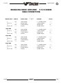
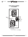
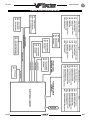
TROUBLESHOOTING
June 1998
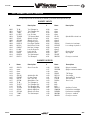
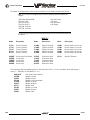
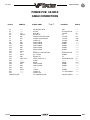
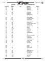
COMMON ABBREVIATIONS USED IN HAAS MACHINES
AC
AMP
APC
APL
ASCII
ATC
ATC FWD
ATC REV
BHCS
CB
CC
CCW
CNC
CNCR SPINDLE
CRC
CRT
CW
DB
DC
DGNOS
DIR
DNC
ENA CNVR
EOB
EOF
EPROM
E-Stop
FHCS
FT
FU
FWD
GA
HHB
HP
HS
ID
IN
IOPCB
LB
LED
LO CLNT
LOW AIR PR
LVPS
MCD RLY BRD
MDI
MEM
M-FIN
MM
MOCON
MOTIF
MSG
NC
96-8100
Alternating Current
Ampere
Automatic Pallet Changer
Automatic Parts Loader
American Standard Code for Information Interchange
Automatic Tool Changer
Automatic Tool Change Forward
Automatic Tool Changer Reverse
Button Head Cap Screw
Circuit Breaker
Cubic Centimeter
Counter Clock Wise
Computerized Numeric Control
Concurrent Spindle with axis motion
Cyclic Redundancy Check Digit
Cathode Ray Tube
Clock Wise
Draw Bar
Direct Current
Diagnostic
Directory
Direct Numerical Control
Enable Conveyor
End Of Block
End Of File
Erasable Programmable Read Only Memory
Emergency Stop
Flat Head Cap Screw
Foot
Fuse
Forward
Gauge
Hex Head Bolts
Horse Power
Horizontal Series Of Machining Centers
Inside Diameter
Inch
Input Output Printed Circuit Board
Pound
Light Emitting Diode
Low Coolant
Low Air Pressure
Low Voltage Power Supply
M-Code Relay Board
Manual Data Input
Memory
M-Code Finished
Millimeter
Motor Control
Motor Interface
Message
Numerical Control
1
TROUBLESHOOTING
NC
NO
OD
OPER
PARAM
PCB
PGM
POR
POSIT
PROG
PSI
PWM
RAM
REPT RIG TAP
RET
REV CNVR
RJH
RPDBDN
RPDBUP
RPM
S
SDIST
SFM
SHCS
SIO
SKBIF
SP
T
TC
TIR
TNC
TRP
TS
TSC
VF
VF-E
VMC
2
June 1998
Normally Closed
Normally Open
Outside Diameter
Operator
Parameter
Printed Circuit Board
Program
Power On Reset
Positions
Program
Pounds Per Square Inch
Pulse Width Modulation
Random Access Memory
Repeat Rigid Tap
Return
Reverse Conveyor
Remote Jog Handle
Rotary Pallet Draw Bar Down
Rotary Pallet Draw Bar Up
Revolutions Per Minute
Spindle Speed
Servo Distribution PCB
Surface Feet Per Minute
Socket Head Cap Screw
Serial Input/Output
Serial Key Board Inter Face PCB
Spindle
Tool Number
Tool Changer
Total Indicated Runout
Tool Nose Compensation
Tool Release Piston
Tail Stock
Through The Spindle Coolant
Vertical Mill (very first)
Vertical Mill- Extended
Vertical Machining Center
96-8100
TROUBLESHOOTING
June 1998
1. TROUBLESHOOTING
This section is intended for use in determining the solution to a known problem. Solutions given are intended
to give the individual servicing the CNC a pattern to follow in, first, determining the problems source and,
second, solving the problem.
The troubleshooting tips are organized in this section according to the area of the CNC that may be giving
sign of a problem. (Ex.: Out-of round circles in drilling will be found under the heading General Machine
Operation - Accuracy).
If the problem you are experiencing cannot be found under the heading you expect, please try several other
possible headings. If the problem is still not found, contact Haas Automation for further details.
BEFORE YOU BEGIN:
USE COMMON SENSE
Many problems are easily overcome by correctly evaluating the situation. All machine operations are
composed of a program, tools, and tooling. You must look at all three before blaming one as the fault area.
If a bored hole is chattering because of an overextended boring bar, dont expect the machine to correct the
fault. Dont suspect machine accuracy if the vise bends the part. Dont claim hole mis-positioning if you dont
first center-drill the hole.
FIND THE PROBLEM FIRST
Many mechanics tear into things before they understand the problem, hoping that it will appear as they go.
We know this from the fact that more than half of all warranty returned parts are in good working order. If
the spindle doesnt turn, remember that the spindle is connected to the gear box, which is connected to the
spindle motor, which is driven by the spindle drive, which is connected to the I/O BOARD, which is driven
by the MOCON, which is driven by the processor. The moral here is dont replace the spindle drive if the belt
is broken. Find the problem first; dont just replace the easiest part to get to.
DONT TINKER WITH THE MACHINE
There are hundreds of parameters, wires, switches, etc., that you can change in this machine. Dont start
randomly changing parts and parameters. Remember, there is a good chance that if you change something,
you will incorrectly install it or break something else in the process. Consider for a moment changing the
processors board. First, you have to download all parameters, remove a dozen connectors, replace the
board, reconnect and reload, and if you make one mistake or bend one tiny pin it WONT WORK. You always
need to consider the risk of accidentally damaging the machine anytime you work on it. It is cheap insurance
to double-check a suspect part before physically changing it. The less work you do on the machine the
better.
96-8100
3
TROUBLESHOOTING
June 1998
1.1 GENERAL MACHINE OPERATION
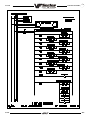
MACHINE NOT RUNNING
´
Machine cannot be powered on.
l
l
l
l
l
l
l
l
´
Machine can be powered on, but turns off by itself.
l
l
l
l
l
l
l
l
´
l
l
l
l
l
l
l
Check keyboard cable (700B) from VIDEO to SKBIF PCB.
Replace keypad (see "Electrical Service").
Replace SKBIF PCB (see "Electrical Service").
Constant E-Stop Condition (will not reset)
l
4
Check for green POWER LED at front of CRT.
Check for power connections to CRT from IOPCB.
Close doors and Zero Return machine (possible bad monitor).
Check video cable (760) from VIDEO PCB to CRT.
Check for lights on the processor.
Replace CRT (see "Electrical Service").
Machine turns on, CRT works, but no keyboard keys work.
l
´
Check settings #1 and #2 for Auto Off Timer or Off at M30.
Check alarm history for OVERVOLTAGE or OVERHEAT shutdown.
Check AC power supply lines for intermittent supply.
Check wiring to POWER OFF button on front control panel.
Check connection between 24V transformer and K1 contactor.
Replace IOPCB (see "Electrical Service").
Check Parameter 57 for Power Off at E-STOP.
Replace MOTIF or MOCON PCB (see "Electrical Service").
Machine turns on, keyboard beeps, but no CRT display.
l
´
Check input voltage to machine (see "Electrical Service").
Check main circuit breaker at top right of electrical cabinet; switch must be at the on position.
Check overvoltage fuses (see "Electrical Service").
Check wiring to POWER OFF button on front control panel.
Check wiring to AUTO OFF relay to IOPCB.
Check connection between 24V transformer and K1 contactor
Replace IOPCB (see "Electrical Service").
Replace POWER PCB (see "Electrical Service").
Check Hydraulic counterbalance pressure, low pressure switches and cabling.
96-8100
TROUBLESHOOTING
June 1998
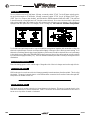
VIBRATION
Vibration is a subjective evaluation with perceptions varying among individuals, making it difficult to
determine in mild cases if there is an actual problem. Because the VF Series uses a gear head, it will be
noisier than a direct drive or belt system. In obvious cases, it is a matter of determining the source - which
is not easy, since all parts rotate together and sound can be transferred readily. Vibrations also need to be
distinguished from noise such as a bad bearing. We will assume that vibrations would be something that
could be felt by putting your hand on the spindle covers. One crude method of measurement would be to
take an indicator on a magnetic base extended 10 inches between the table and spindle housing and observe
the reading of the indicator. A reading of more than .001 would indicate excessive vibration. The two
common sources of noise are the spindle and axis drives. Most complaints about vibration, accuracy, and
finish can be attributed to incorrect machining practices such as poor quality or damaged tooling, incorrect
speeds or feeds, or poor fixturing. Before concluding that the machine is not working properly, ensure that
good machining practices are being observed. These symptoms will not occur individually (Ex. A machine
with backlash may vibrate heavily, yielding a bad finish.). Put all of the symptoms together to arrive at an
accurate picture of the problem.
´
l
´
l
Machine vibrates while jogging the axis with the hand wheel.
The HAAS control uses very high gain accelerations curves. This vibration as you jog is simply the
servos quickly trying to follow the handle divisions. If this is a problem, try using a smaller division on
the handle. You will notice the vibration more at individual clicks than when you are turning the handle
faster. This is normal.
The machine vibrates excessively in a cut.
This is a tough one to call because machining practices come into play. Generally speaking, the least
rigid element of a cut is the tool because it is the smallest part. Any cutter will vibrate if pushed beyond
its tensile strength. In order to eliminate the machine as the source of the problem, you need to check
the spindle and the backlash of the axes as described in the following sections. Once machining
practices have been eliminated as the source of vibration, observe the machine in both operation and
cutting air. Move the axes (individually) without the spindle turning and then turn the spindle without
moving the axes. Isolate whether the vibration comes from the spindle head or from an axis. Isolate
the source of vibration per "Spindle", "Servo Motors/Leadscrews", and "Gearbox and Spindle Motor"
sections.
ACCURACY
Before you complain of an accuracy problem, please make sure you follow these simple dos and donts:
l
l
l
l
l
l
l
l
l
l
l
l
96-8100
Ensure that the machine has been sufficiently warmed up before cutting parts. This will eliminate
mispositioning errors caused by thermal growth of the leadscrews (see "Thermal Growth" section).
Dont ever use a wiggler test indicator for linear dimensions. They measure in an arc and have
sine/cosine errors over larger distances.
Dont use magnetic bases as accurate test stops. The high accel/decel of the axis can cause them
to move.
Dont attach magnetic base to the sheet metal of the spindle head or table.
Don't mount the magnetic base on the spindle dogs.
Dont check for accuracy/repeatability using an indicator with a long extension.
Ensure that test indicators and stops are absolutely rigid and mounted to machined casting surfaces
(e.g. spindle head casting, spindle nose, or the table).
Don't rapid to position when checking accuracy. The indicator may get bumped and give an
inaccurate reading. For best results, feed to position at 5-10 inches per minute.
Check a suspected error with another indicator or method for verification.
Ensure that the indicator is parallel to the axis being checked to avoid tangential reading errors.
Center drill holes before using jobber length drills if accuracy is questioned.
Once machining practices have been eliminated as the source of the problem, determine specifically
what the machine is doing wrong.
5
TROUBLESHOOTING
´
Machine will not interpolate a round hole.
l
l
´
l
l
l
l
l
l
Check
Check
Check
Check
for thermal growth of the leadscrew (see "Thermal Growth" section).
that the machine is level (see "Installation" section).
for backlash (see "Servo Motors/Leadscrews" section).
the squareness of the X axis to the Y axis.
Machine leaves large steps when using a shell mill.
l
l
l
´
Check for thermal growth of the leadscrew (see "Thermal Growth" section).
The spindle is not parallel to the Z axis. Check the spindle sweep to the table and the squareness
of the Z axis with a cylinder square. If available use a spindle master bar and indicate the spindle
to the Z axis.
Machine mis-positions holes.
l
´
Check that the machine is level (see "Installation" section).
Check the sweep of the machine (see "Spindle Sweep Adjustment" section).
Bored holes are out of round or out of position.
l
´
Check that the machine is level (see "Installation" section).
Check for squareness in the Z axis.
Machine bores holes out-of-round.
l
´
Check that the machine is level (see "Installation" section).
Check for backlash ("Servo Motors/Leadscrews" section).
Bored holes do not go straight through the workpiece.
l
´
June 1998
Check that the machine is level (see "Installation" section).
Check the sweep of the machine (see "Spindle Sweep Adjustment" section).
Cutter diameter too large for depth of cut.
Boring depth inaccurate
l
l
Check for thermal growth of the leadscrew (see "Thermal Growth" section).
Check the hydraulic counterbalance system pressure. If pressure is low, check for:
Ø abnormal noises from counterbalance system
Ø oil leaks (esp. at fittings and at filter at top of cylinder)
Ø bound cylinder
FINISH
´ Machining yields a poor finish.
l
l
l
l
l
l
6
Check
Check
Check
Check
Check
Check
for gearbox vibration. This is the most common cause of a poor finish.
for backlash ("Accuracy/Backlash" section)
the condition of the tooling and the spindle.
for spindle failure.
the condition of the servo motors.
that the is machine level.
96-8100
TROUBLESHOOTING
June 1998
THERMAL GROWTH
A possible source of accuracy and positioning errors is thermal growth of the leadscrew. As the machine
warms up, the leadscrews expand in all three linear axes, causing accuracy and positioning errors, or
inaccurate boring depths. This is especially critical in jobs that require high accuracy, machining multiple
parts in one setup, or machining one part with multiple setups.
Note: On machines equipped with linear scales, thermal growth will not affect machine
positioning or accuracy. However, it is still recommended that the machine be warmed
up before cutting parts.
Note: The leadscrew will always expand away from the motor end.
VERIFY THERMAL GROWTH
There are a number of ways to verify the problem. The following procedure will verify thermal growth of
the X-axis leadscrew in a machine that has not been warmed up:
1. Home the machine. In MDI mode, press POSIT and PAGE DOWN to the OPER page.
2. Jog to an offset location on the table (example: X-15.0" Y-8.0" ). Select the X axis and press the
ORIGIN key to zero it. Select the Y axis and zero it.
3. Press the OFSET key, then scroll down to G110 (or any unused offset). Cursor to X and press PART
ZERO SET twice. This will set X0, Y0 at this position.
4. Enter the following program. It will start at the new zero position, rapid 10 inches in the X direction,
feed the final .25 inches at 10 inches/min., and then repeat the X movement.
G00 G90 G110 X0 Y0;
X10.0;
G01 X10.25 F10. ;
M99;
5. In order to set up the indicator, run the program in SINGLE BLOCK mode, and stop it when X is at
10.25". Set the magnetic base on the table, with the indicator tip touching the spindle housing in the
X-axis, and zero it.
6. Exit SINGLE BLOCK mode, and run the program for a few minutes. Enter SINGLE BLOCK mode again,
stop the program when X is at 10.25", and take a final reading on the indicator. If the problem is
thermal growth, the indicator will show a difference in the X position.
Note: Ensure the indicator setup is correct as described in "Accuracy" section. Errors in
setup are common, and often incorrectly appear to be thermal growth.
7. A similar program can be written to test for thermal growth in the Y and Z axes, if necessary.
SOLUTIONS
Since there are many variables that affect thermal growth, such as the ambient temperature of the shop and
program feed rates, it is difficult to give one solution for all problems.
Thermal growth problems can generally be eliminated by running a warm-up program for approximately 20
minutes before machining parts. The most effective warm-up is to run the current program, at an offset
Z position above the part or table, with the spindle "cutting air". This will allow the leadscrews to warm up
to the correct temperature and stabilize. Once the machine is at temperature, the leadscrews won't expand
any further, unless they're allowed to cool down. A warm-up program should be run after each time the
machine is left idle.
96-8100
7
TROUBLESHOOTING
June 1998
1.2 SPINDLE
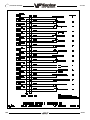
NOT TURNING
´
l
l
l
l
l
l
l
l
l
Spindle not turning.
If there are any alarms, refer to "Alarms" section.
Check that the spindle turns freely when machine is off.
If motor turns but spindle does not, see "Belt Assembly" and "Spindle Motor & Transmission"
sections.
Command spindle to turn at 1800 RPM and check spindle drive display. If display blinks bb, check
spindle orientation switch ("Spindle Orientation" section). If spindle drive does not light the RUN
LED, check forward/reverse commands from IOPCB ("Electrical Service").
Check the wiring of analog speed command from MOTIF PCB to spindle drive (cable 720).
If spindle is still not turning, replace MOTIF PCB ("Electrical Service").
If spindle is still not turning, replace spindle drive ("Electrical Service").
Check for rotation of the gearbox (if applicable) or the motor (VF-0). If the motor or gearbox
operates, check the drive belt ("Belt Assembly" section).
Disconnect the drive belt. If the spindle will not turn, it is seized and must be replaced ("Spindle
Assembly" section).
Note: Before using the replacement spindle, the cause of the previous failure must be
determined.
NOISE
Most noises attributed to the spindle actually lie in the motor/gearbox or drive belt of the machine. Isolate
the sources of noise as follows:
´
Excessive noise coming from the spindle head area.
On VF-1 through 6 models, first determine if the noise is related to the RPM of the motor or the RPM
of the spindle. For example: If the noise appears at 2000 RPM in high gear, listen for a similar noise
at 500 RPM in low gear. If the same noise persists, the problem lies with the gearbox. If the noise
disappears, the problem could be either the gearbox or the spindle, and further testing is necessary.
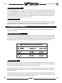
Note: The gear ratio is 1:1.25 in high gear, and 3.2:1 in low gear.
l
l
l
l
8
Remove the head covers and check the machines drive belt tension ("Tension Adjustment" section).
Ø If the noise persists, turn the drive belt over on the pulleys. If the noise is significantly different,
the belt is at fault. Replace the belt ("Belt Assembly" section).
Ø If the noise does not change, remove the belt and go on to the next step.
Check the pulleys for excessive runout (more than 0.003" axial or radial).
Run the motor (VF-0) or the gearbox (VF-1, VF-2, VF-3) with the drive belt disconnected. If the noise
persists, the problem lies with the gearbox/motor. If it disappears, go on to the next step.
Check for the correct amount of lubrication to the spindle bearings (0.5-1.0 cc every two hours) in
a an air mist-lubricated spindle.
Ø If the spindle is not getting lubrication, correct the problem per the lube and air diagram at the
back of this manual and replace the spindle ("Spindle Assembly" section).
Ø If the spindle is getting lubrication, replace the spindle ("Spindle Assembly" section).
96-8100
TROUBLESHOOTING
June 1998
OVERHEATING
When investigating complaints of overheating, a temperature probe must be used to accurately check the
temperature at the top of the spindle taper. The temperature displayed in Diagnostics is not relevant. A
machine that runs at high RPM continuously will have a much warmer spindle than a machine that runs at
a lower RPM. New spindles tend to run much warmer than spindles that have already been broken in. In
order to run a valid test on a new spindle, ensure that it is properly broken in.
To break in a spindle, run the following program (it will take approximately 6 hours):
N100 S300 M03
G04 P900.
M05
G04 P900.
N200 S1000 M03
G04 P900.
M05
G04 P900.
N300 S2000 M03
G04 P900.
M05
G04 P900.
G04 P900.
N400 S3000 M03
G04 P900.
M05
G04 P900.
G04 P900.
N500 S4000 M03
G04 P900.
M05
G04 P900.
G04 P900.
N600 S5000 M03
G04 P900.
M05
G04 P900.
G04 P900.
N700 S6000 M03
G04 P900.
M05
G04 P900.
G04 P900.
N800 S7500 M03
G04 P900.
M05
G04 P900.
G04 P900.
M99
Note: This program will step the spindle speed from 300 RPM up to either 5000 or 7500
RPM at regular intervals of time, stop the spindle and allow it to cool to room temperature, then restart it so the temperature can be monitored.
l
If at any time during this procedure the spindle temperature rises above 150 degrees, start the
procedure over from the beginning.
If the spindle fails this test for any reason, check the following:
l
Check for correct amount of lubrication.
Note: Over lubrication is a common source of overheating. Check the oil flow carefully.
l
l
Check the drive belt tension. Too-tight belts will cause heating of the top bearing in the spindle
housing.
Ensure that the correct oil is being used (refer to "Maintenance Schedule").
STALLING / LOW TORQUE
Generally, complaints of stalling or low torque relate to incorrect tooling or machining practices. A spindle
that is tending to seize will yield a poor finish machining, run very hot and very loud. Investigate machining
problems before concluding the problem exists with the spindle or spindle drive.
96-8100
9
TROUBLESHOOTING
June 1998
SPINDLE DRIVE
Low line voltage may prevent the spindle from accelerating properly. If the spindle takes a long time to
accelerate, slows down or stays at a speed below the commanded speed with the load meter at full load,
the spindle drive and motor are overloaded. High load, low voltage, or too fast accel/decel can cause this
problem.
If the spindle is accelerated and decelerated frequently, the regenerative load resistor on top of the control
may heat up. If this resistor heats beyond 100 0 C, a thermostat will generate an overheat alarm.
If the regen load resistors are not connected or open, this could then result in an overvoltage alarm. The
overvoltage occurs because the regenerative energy being absorbed from the motor while decelerating is
turned into voltage by the spindle drive. If this problem occurs, the possible fixes are to slow the decel rate
or reduce the frequency of spindle speed changes.
ORIENTATION
´
Spindle loses correct orientation.
Non Vector Drive
l
l
l
l
l
Check alarm history, looking for spindle overload and axis overcurrent alarms. These alarms mean
the machine is not being properly operated.
Check the orientation ring for tightness. Ensure the shaft on which the ring mounts is clean and is free
of grease and oil.
Check the orientation ring for cracks near the bolt holes or near the balancing holes.
Ø If there are cracks, replace the ring.
Check the shot pin on the gearbox for binding, damage, and proper operation. Replace it if it is
damaged.
Check the switch on the shot pin against the Diagnostic display. Replace the switch if it is found to
be faulty.
Vector Drive
l
l
l
Check alarm history. Look for Spindle Z Fault, or Spindle Reference Missing alarms. If these alarms
exist, there may be a defective spindle encoder, or a broken ground or shield connection.
Check parameters.
Check for a mechanical slip at the contact points of all components between the spindle and the
spindle encoder
TOOLS STICKING IN TAPER
´
Tool sticking in the taper causes ATC to be pulled up; accompanied by a popping
noise as the tool holder pops out of the spindle taper.
Note: This problem may occur after loading a cold tool into a hot spindle (a result of
thermal expansion of the tool holder inside the spindle taper). It may also occur due to
heavy milling, milling with long tooling, or cuts with heavy vibration. If sticking only
occurs during these situations, no service is necessary. If tool is pulled out of extractors
due to a tool stuck in the taper then the unclamp switch is not adjusted correctly or the
switch could be bad.
l
l
10
Check the condition of the tooling, verifying the taper on the tooling is ground and not turned. Look
for damage to the taper caused by chips in the taper or rough handling. If the tooling is suspected,
try to duplicate the symptoms with different tooling.
Check the condition of the spindle taper. Look for damage caused by chips or damaged tooling. Also,
look for damage such as deep gouges in the spindle taper caused by tool crashing.
96-8100
TROUBLESHOOTING
June 1998
l
l
l
l
Duplicate the cutting conditions under which the deflection occurs, but do not execute an automatic
tool change. Try instead to release the tool using the tool release button on the front of the spindle
head. If sticking is observed, the deflection is not caused by improper ATC adjustment, but is a
problem in the spindle head on the machine.
Ensure the spindle is not running too hot.
Check air supply.
Check drawbar height adjustment.
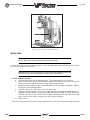
1.3 SERVO MOTORS / LEADSCREWS
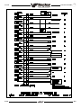
NOT OPERATING
All problems that are caused by servo motor failures should also register an alarm. Check the alarm history
to determine the problems cause before any action is taken.
´
Servo motor is not functioning.
l
l
l
l
l
l
l
l
l
Check the power cable from rear electrical cabinet to ensure connection is tight.
Encoder is faulty or contaminated (Alarms 139-142, 153-156, 165-168, 182-185). Replace motor
assembly on brushless machines, replace the encoder on brush machines.
Open circuit in motor (Alarms 139-142, 153-156, 182-185). Replace motor assembly ("Axis Motor
Removal / Installation").
Motor has overheated, resulting in damage to the interior components (Alarms 135-138, 176).
Replace motor assembly ("Axis Motor Removal/Installation").
Wiring is broken, shorted, or missing shield (Alarms 153-156, 175, 182-185).
Dust in the motor from brushes has shorted out the motor (VF-E only) (Alarms 153-156, 175, 182185). Replace motor assembly ("Axis Motor Removal/Installation").
Motor has overheated; no damage to the interior components. OVERHEAT alarm has been triggered.
After thorough check of motor (DO NOT DISASSEMBLE!), take necessary steps to eliminate the
problem and alarm to resume operation. If motor is still inoperable, replace motor assembly
("Axis Motor Removal/Installation").
Check for broken or loose coupling between the servo motor and the lead screw. Replace or repair
the coupling ("Axis Motor Removal/Installation")
Check for a damaged lead screw, and replace if necessary ("Lead Screw Removal and Installation"
section).
NOTE: If a lead screw fails, it is most often due to a failed bearing sleeve. When replacing the lead screw in an older machine, always replace the bearing sleeve with the
current angular contact bearing sleeve ("Bearing Sleeve Removal and Installation"
section).
NOISE
Lead screw noise is usually caused by a lack of lubrication and is usually accompanied by heating. Other
causes are misalignment, bearing sleeve damage, or ball nut damage. Check the alarm history of the machine
and look for axis overcurrent and following error alarms.
Note: Do not replace lead screws or bearing sleeves without due consideration; they are
extremely durable and reliable. Verify that customer complaints are not due to tooling,
programming, or fixturing problems.
96-8100
11
TROUBLESHOOTING
´
Servo motor noise.
l
l
l
´
June 1998
Disconnect the servo motor from the lead screw and rotate by hand. If the noise persists, replace
the motor assembly ("Axis Motor Removal/Installation" section).
Noise is caused by motor brushes (VF-E only). No problems will occur and noise should eventually
go away.
Noise is caused by bearings. Rolling, grinding sound is heard coming from the motor. ENSURE NOISE
IS NOT COMING FROM THE BRUSHES. If bearings are making a consistently loud sound, replace the
bearing sleeve.
Lead screw noise.
l
l
Ensure oil is getting to the lead screw through the lubrication system (See Air and Oil Diagrams).
Look for a plugged metering valve.
Check for damage to the bearing sleeve.
Note: The current angular contact design sleeve has a fixed pre-load; it cannot be
adjusted.
l
Run the axis back and forth. The motor will get very hot if the bearing sleeve is damaged. If so, turn
the axis by hand and feel for roughness in the lead screw. Loosen the clamp nuts at both ends of the
lead screw. If the symptom disappears, replace the bearing sleeve. Be certain to check for damage
to the lead screw shaft where the bearing sleeve is mounted.
Ø If the noise persists, the lead screw is damaged and must be replaced. When replacing the lead
screw in an older machine, always replace the bearing sleeve with the current angular contact
design bearing sleeve.
l
Check the lead screw for misalignment. If incorrect, perform alignment procedure.
Misalignment in the lead screw itself will tend to cause the lead screw to tighten up and make
excessive noise at both ends of the travel. The ballnut may get hot. Misalignment radially at the yoke
where the lead screw ball nut mounts is indicated by heating up of the ball nut on the lead screw, and
noise and tightness through out the travel of the lead screw. Misalignment at the yoke where the ball
nut mounts is indicated by noise and tightness at both ends of the travel of the lead screw. The ball
nut may get hot.
l
ACCURACY / BACKLASH
Accuracy complaints are usually related to tooling, programming, or fixturing problems. Eliminate these
possibilities before working on the machine.
´
Poor mill table-positioning accuracy.
l
l
l
Check for a loose encoder on the servo motor. Also, ensure the key in the motor or the lead screw
is in place and the coupling is tight (Brush machines only).
Check parameters for that axis
Check for backlash in the lead screw as outlined below:
INITIAL PREPARATION -
Turn the VMC ON. ZERO RET the machine and move the mill table to the approximate center of its travel in
the X and Y directions. Move the spindle head to approximate center of the Z-axis travel, also.
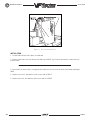
CHECKING X-AXIS:
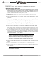
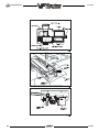
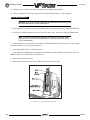
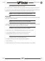
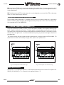
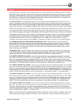
1.
12
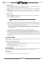
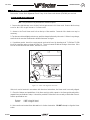
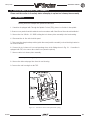
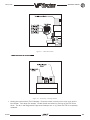
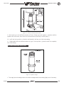
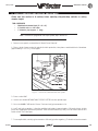
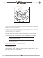
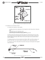
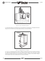
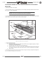
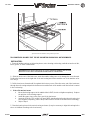
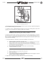
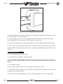
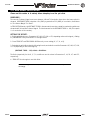
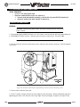
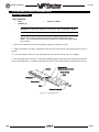
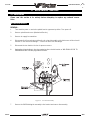
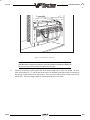
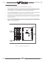
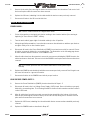
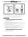
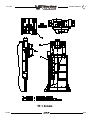
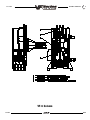
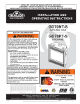
Set up a dial indicator and base on the mill table as shown in Fig. 1-1.
96-8100
TROUBLESHOOTING
June 1998
Figure 1-1. Dial indicator in position to check X-axis.
2.
Set dial indicator and the Distance to go display in the HANDLE JOG mode to zero as follows:
Ø Zero the dial indicator.
Ø Press the MDI button on the control panel.
Ø Press the HANDLE JOG button on the control panel.
The Distance to go display on the lower right hand corner should read:
X=0
Y=0
Z=0
3.
Set the rate of travel to .001 on the control panel and jog the machine .010 in the positive (+) X
direction. Jog back to zero (0) on the display. The dial indicator should read zero (0) ± .0001.
4.
Repeat Step 3 in the negative (-) direction.
TOTAL DEVIATION BETWEEN THE DIAL INDICATOR AND THE CONTROL PANEL DISPLAY SHOULD NOT
EXCEED .0002.
An alternate method for checking backlash is to place the dial indicator as shown in Fig. 3-1 and manually
push on the mill table in both directions. The dial indicator should return to zero after releasing the table.
Note: The servos must be on to check backlash by this method.
CHECKING Y-AXIS:
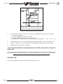
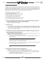
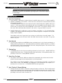
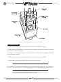
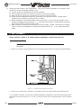
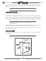
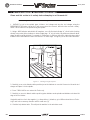
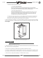
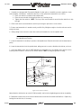
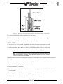
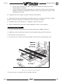
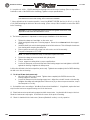
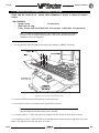
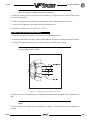
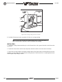
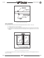
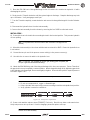
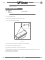
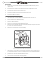
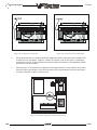
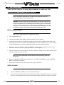
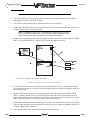
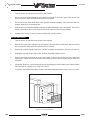
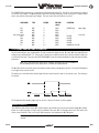
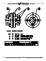
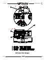
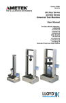
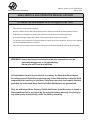
1. Set up a dial indicator and base on the mill table as shown in Fig. 1-2.
96-8100
13
TROUBLESHOOTING
June 1998
Figure 1-2. Dial indicator in position to check Y-axis.
2.
Set dial indicator and the Distance to go display in the HANDLE JOG mode to zero as follows:
Ø Zero the dial indicator.
Ø Press the MDI button on the control panel.
Ø Press the HANDLE JOG button on the control panel.
The Distance to go display on the lower right hand corner should read:
X=0
Y=0
Z=0
3.
Set the rate of travel to .001 on the control panel and jog the machine .010 in the positive (+) Y
direction. Jog back to zero (0) on the display. The dial indicator should read zero (0) ± .0001.
4.
Repeat Step 3 in the negative (-) direction.
TOTAL DEVIATION BETWEEN THE DIAL INDICATOR AND THE CONTROL PANEL DISPLAY SHOULD NOT
EXCEED .0002.
An alternate method for checking backlash is to place the dial indicator as shown in Fig. 1-2 and manually
push on the mill table in both directions. The dial indicator should return to zero after releasing the table.
Note: The servos must be on to check backlash by this method.
CHECKING Z-AXIS:
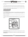
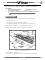
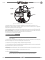
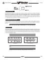
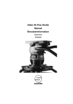
1.
14
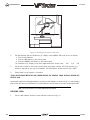
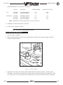
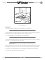
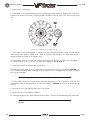
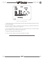
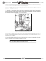
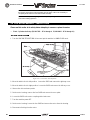
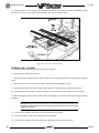
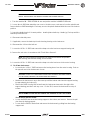
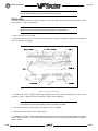
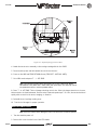
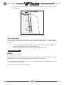
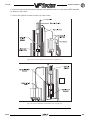
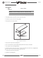
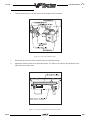
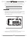
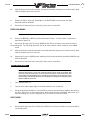
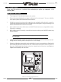
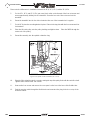
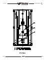
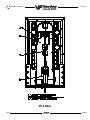
Set up a dial indicator and base on the mill table as shown in Fig. 1-3.
96-8100
TROUBLESHOOTING
June 1998
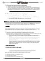
2.
Manually push up and down on the spindle head while listening for a clunk. Also, watch for any rapid
change in the dial indicator. Either of these indicate possible backlash.
Note: Servos must be on to check for backlash in the Z-axis.
Note: Do not mistake deflection for backlash in the system.
Figure 1-3. Dial indicator in position to check Z-axis.
If backlash is found in the system, check for the following possible causes:
l
Loose SHCS attaching the ball nut to the nut housing. Tighten the SHCS as described in Mechanical
Service.
l
Loose SHCS attaching the nut housing to the mill table, spindle head, or saddle, depending on the axis.
Tighten the SHCS as described in Mechanical Service.
l
Loose clamp nut on the bearing sleeve. Tighten the SHCS on the clamp nut.
l
Loose motor coupling. Tighten as described in Mechanical Service.
l
Broken or loose flex plates on the motor coupling.
Note: The coupling cannot be serviced in the field and must be replaced as a unit if it is
found to be defective.
l
l
l
l
l
96-8100
Loose SHCS attaching the bearing sleeve to the motor housing. Tighten as described in "Lead Screw
Removal and Installation".
Defective thrust bearings in the bearing sleeve. Replace the bearing sleeve as outlined in "Bearing
Sleeve Removal and Installation".
Loose SHCS attaching the axis motor to the motor housing. If the SHCS are found to be loose, inspect
the motor for damage and if none is found, tighten as described in "Axis Motor Removal/Installation".
If damage is found, replace the motor.
Incorrect backlash compensation number in the parameter in the machine. Check Parameters 13, 27,
and 41.
Worn lead screw.
15
TROUBLESHOOTING
June 1998
VIBRATION
´
Excessive servo motor vibration.
l
l
l
If no A axis is present, swap the suspected bad servo motor with the A driver and check to see
if there is a driver problem. If needed, replace the DRIVER PCB ("Electrical Service" section).
Check all Parameters of the suspected axis against the Parameters as shipped with the machine. If
there are any differences, correct those and determine how the Parameters were changed.
PARAMETER LOCK should normally be on.
A bad motor can cause vibration if there is an open or short in the motor. A short would normally
cause a GROUND FAULT or OVERCURRENT alarm; check the ALARMS. An ohmmeter applied to the
motor leads should show between 1 and 3 ohms between leads, and over 1 megohm from leads to
chassis. If the motor is open or shorted, replace.
OVERHEATING
´
Servo motor overheating.
l
l
If a motor OVERHEAT alarm occurs (ALARMS 135-138), check the Parameters for an incorrect
setting. Axis flags in Parameters 1, 15, or 29 can invert the overheat switch (OVER TEMP NC).
If the motor is actually getting hot to the touch, there is excessive load on the motor. Check the users
application for excessive load or high duty cycle. Check the lead screw for binding ("Accuracy/
Backlash" section). If the motor is binding by itself, replace in accordance with "Axis Motor Removal/
Installation".
FOLLOWING ERRORS
´
FOLLOWING ERROR (VF-E only) or SERVO ERROR TO0 LARGE alarms 103-106, 187 occur
on one or more axes sporadically.
l
l
l
l
l
´
Check DC bus voltage on diagnostics page #2 (VF-E only). Verify this voltage on the drive cards in
the control panel. If it is at the low side of the recommended voltages, change the transformer tap
to the next lower voltage group as explained in the Installation Manual.
Check motor wiring for a short.
Replace driver card ("Electrical Service").
Replace servo motor ("Axis Motor Removal/Installation").
Replace encoder (VF-E only)
Z-axis motor overcurrent.
Brake won't release (leadscrew won't rotate)
Alarm not cleared
l Low counterbalance pressure
l Check Z axis parameters
l Check the lead screw for binding
l Check motor and cable for shorts
l Replace amplifier (drive card on a VF-E)
l
VF-6 with Z axis brake only
l Brake power fuse blown
l Brake power transformer blown
l Brake power rectifier blown
l Cabling pinched
l Brake failed
16
96-8100
TROUBLESHOOTING
June 1998
1.4 AUTOMATIC TOOL CHANGER
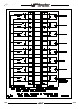
DEFLECTION
Deflection is usually caused by ATC misalignment, and sometimes caused by damaged or poor quality
tooling, a damaged spindle taper, or a damaged drawbar or poor air supply. Before beginning any
troubleshooting, observe the direction of the ATC deflection.
´
During a tool change, ATC appears to be pushed down.
l
l
Check to see if pull studs on the tool holder are correct and tight.
Check the adjustment of the Z offset ("Setting Parameter 64").
Note: If the offset is incorrect a tool changer crash has occured and a thorough
inspection of the ATC is necessary at this time.
l
l
l
l
l
´
Check the adjustment of the Z offset. Check parameters 71, 72, and 143 against the values that
are in the documentation sent with the machine.
Ensure the tool holders are held firmly in place by the extractor forks.
Ensure the balls on the drawbar move freely in the holes in the drawbar when the tool release button
is pressed. If they do not move freely, the a ATC will be pushed down about 1/4" before the tool
holder is seated in the taper, resulting in damage to the roller bolts on the ATC shuttle. Replace the
drawbar.
Check Drawbar height adjustment.
If TSC, check for excessive coolant tip wear.
Tool holder sticking in the spindle taper causes the ATC to be pulled up as the spindle head is
travelling the distance specified in parameter 71; accompanied by a popping noise as the tool holder
pops out of the spindle taper.
Note: This problem may occur after loading a cold tool into a hot spindle (a result of
thermal expansion of the tool holder inside the spindle taper. It may also occur in cuts
with heavy vibration. If sticking occurs only during these circumstances, no service is
necessary.If tool is pulled out of extractors due to a tool being stuck in the taper then the
unclamp switch is not adjusted correctly or the switch could be bad.
l
l
l
l
96-8100
Check the condition of the customers tooling, verifying the taper on the tool holder is ground and
not turned. Look for damage to the taper caused by chips in the taper or rough handling. If the
tooling is suspected, try to duplicate the symptoms with different tooling.
Check the condition of the spindle taper. Look for damage caused by chips or damaged tooling.
Also, look for damage such as deep gouges in the spindle taper caused by tool crashing. See "Spindle
Assembly" section for spindle cartridge replacement.
Duplicate the cutting conditions under which the deflection occurs, but do not execute an automatic
tool change. Try instead to release the tool using the tool release button on the front of the spindle
head. If sticking is observed, the deflection is not caused by improper ATC adjustment, but is a
problem in the spindle or tool release piston. See the "Spindle Assembly" section in Mechanical
Sevice for spindle cartridge replacement.
Check air supply pressure it should be 85 psi (min). An air pressure drop of no more than 10 psi
during tool release is acceptable. An air pressure drop greater than 10 psi is caused by a supply line
restriction or an undersize supply line. Use of quick couplers ( 1/ 4 ") can cause restriction. Directly
connecting the air hose to a barb fitting can help.
17
TROUBLESHOOTING
´
June 1998
During a tool change, ATC appears to be pulled up; no popping noises.
l
Check the adjustment of the Z offset ("Setting Parameter 64" section).
Note: If the offset is incorrect, a tool changer crash has occurred, and a thorough
inspection of the ATC is necessary at this time.
l
Ensure the roller bolts on the shuttle of the ATC are tight against the V-guides on the ATC holding
arm.If the lower right roller bolt is loose against the V-guide, the upper right bolt is probably bent.
See the following section ("ATC Crashing") or "Roller Bolt Replacement", for roller bolt replacement.
Note: Bent roller bolts are a symptom of another problem with the ATC. Repair the bent
roller bolt and then isolate the ATC problem.
l
l
´
Tool holders twist against extractor fork during a tool change.
l
´
Check Parameter 71 against the values that are in the documentation sent with the machine.
Ensure the balls on the drawbar move freely in the holes in the drawbar when the tool release button
is pressed. If they do not move freely, the ATC will be pushed down about ¼ before the tool holder
is seated in the taper, resulting in damage to the roller bolts on the ATC shuttle. Replace drawbar.
Check the alignment of the ATC in the X and Y axes ("Automatic Tool Changer Alignment" section).
Tool holders spin at all pockets of the ATC when the ATC shuttle retracts.
l
ATC is misaligned in the Y axis. Realign ATC ("Automatic Tool Changer Alignment" section).
Note: Observe the direction the tool holder rotates, as this will be the direction in which
the Y axis of the ATC needs to be moved.
´
Tool holders spin only at certain pockets of the ATC when the ATC shuttle retracts.
l
Check all the extractor forks to ensure they are centered in the pocket of the ATC. Also, see above.
See "Extractor Fork Replacement" section, if necessary.
Note: If the ATC shows the problem as described here, each extractor fork must be
checked and centered to eliminate the possibility of the ATC being aligned against an
incorrectly-centered fork.
CRASHING
Crashing of the ATC is usually a result of operator error. The most common ATC crashes are outlined as
follows:
´
Shuttle crashes into spindle when a tool change is commanded (tool holder is in the pocket
facing the spindle head).
l
Rotate the carousel to an empty pocket. Refer to the Programming and Operation manual for correct
operation.
Note: This crash is fairly common and is a result of operator error. If the ATC is stopped
in the middle of tool change cycle, the operator must command the ATC to an empty
pocket before the machine will operate correctly. Repeated crashes of this type can
damage the I/O board, the slip clutch, and the shuttle motor in the ATC.
18
96-8100
TROUBLESHOOTING
June 1998
´
During a tool change spindle crashes into top of the tool holder after a turret rotation.
When the spindle head moves down over the top of the tool holder during a tool change, the pull stud
will bind inside the drawbar bore of the spindle, forcing the ATC down, bending the upper right roller
bolt on the ATC shuttle or completely breaking it off. Tool holder is not held correctly in the extractor fork,
possibly held only in one side of the extractor and at an odd angle.
l
´
´
During a tool change spindle crashes into top of the tool holder after a turret rotation.
The balls in the drawbar do not move freely, causing the ATC to be forced down far enough to bend the
upper right roller bolt or completely break it off.
l
Ensure the balls on the drawbar move freely in the holes in the drawbar when the tool release button
is pressed. If this failure occurs, check all of the extractor forks on the ATC for damage and repair
the spindle drawbar.
l
Check drawbar height and set according to the appropriate section, if necessary.
ATC properly deposits a tool holder in the spindle, but the tools are dropped onto the machine
table when the shuttle retracts.
l
´
Inspect the balls and the Belleville springs in the drawbar. See appropriate section and replace
drawbar.
The part or fixture on the mill table crashes into long tooling or into the ATC itself during a tool
change.
l
´
Check all of the extractor forks on the ATC.
Program the machine to move the part out of the way of the ATC. Inspect the pocket involved in the
crash for damage and replace parts as necessary.
The part or fixture on the mill table crashes into long tooling or into the ATC itself when
machining.
l
Either reposition the tools to remove the interference, or program the carousel to rotate long tooling
out of the way of the part (USE THIS ONLY AS A LAST RESORT). CAUTION! If the carousel has to
be programmed to rotate long tools clear of the part, the correct carousel position must be
programmed
back in before a tool change can be executed.
Note: If these crashes occur, thoroughly inspect the ATC for damage. Pay close attention to the extractor forks, the sliding covers on the ATC carousel, and the roller bolts on
the ATC shuttle. See appropriate section for extractor fork replacement.
BREAKAGE
Breakage of the ATC is caused by either very hard and repeated crashes or excessive TSC coolant tip wear.
´
ATC shuttle is broken off of the holding plate.
l
´
ATC extractor forks are damaged after breakage.
l
96-8100
Carefully inspect the bosses on the shuttle casting (where the roller bolts mount) for damage to the
threads or cracks. If any of the bosses are cracked, replace the casting. Realign the tool changer
after repairing the machine.
Check the condition of the mounting holes in the carousel. If the threads are damaged, they must
be repaired or the carousel replaced. See appropriate section for extractor fork replacement.
19
TROUBLESHOOTING
June 1998
NOISY OPERATION
To isolate noise(s) in the ATC, carefully observe the ATC in operation and look for the following:
´
ATC makes noise as the shuttle moves.
l
Check the adjustment of the roller bolts on the ATC ("Roller Bolt Replacement" section). Loose roller
bolts can cause the ATC to make a clunking noise when the shuttle is commanded to move. Tight
roller bolts can cause the shuttle motor to labor excessively, possibly damaging the motor or the
I/O board. In this case, the shuttle may also move too slowly.
l
Check for damage to the trap door on the ATC cover. See appropriate section for trap door
replacement.
l
Check for missing plastic riders on the ATC shutter. See "ATC Trap Door Replacement" for shutter
replacement.
l
Ensure the guide pin mounted to the holding plate is not bent and does not scrape the ATC cover
during movement. See "ATC Trap Door Replacement" for guide pin replacement.
l
Listen for damage to the gear train in the shuttle motor. If the motor is found to be the source of
the noise, replace the motor ("Shuttle Motor Removal" section). DO NOT try to repair the motor or
to further isolate the noise in the motor. ATC makes noise during carousel rotation.
l
Check to ensure the Geneva driver on the turret motor is tight and properly adjusted ("Shuttle
Motor Removal" section). If the Geneva driver is found to be loose, check for damage to the Geneva
star. Any roughness in the slots will require that it be replaced ("Geneva Star Replacement" section).
l
Check the adjustment of the Geneva driver in relation to the Geneva star ("Geneva Star Replacement"
section). If the adjustment is too loose, the carousel will vibrate heavily and make a loud clanking
noise during carousel rotation. If the adjustment is too tight, the turret motor will labor excessively
and the carousel may appear to move erratically.
Note: If the turret motor adjustment is tight for extended periods, the turret motor,
Geneva star, and the I/O board may be damaged. If the adjustment of the Geneva star
appears tight at some pockets and loose at others, the problem lies with the Geneva
star. Check the concentricity of the star relative to the bearing housing on the carousel
assembly. If the concentricity of the star is proven to within specification and the problem
still persists, the Geneva star must be replaced ("Geneva Star Replacement" section).
l
Ensure the screws holding the turret motor to the mounting plate are tight ("Turret Motor Removal"
section).
l
Ensure the screws attaching the motor mounting plate to the shuttle casting are tight.
l
Check for excessive noise in the gear train of the turret motor. See appropriate section for turret
motor replacement.
Note: If the motor is found to be the source of noise, replace the motor assembly (motor,
mounting plate, and Geneva driver).
DO NOT attempt to repair the motor or to further isolate the problem in the motor.
20
96-8100
TROUBLESHOOTING
June 1998
SPINDLE ORIENTATION
A switch is used to sense when the pin drops in to lock the spindle. When the pin drops the switch opens,
indicating orientation is complete. The normally-closed side of this switch is wired to the spindle drive and
commands it into the COAST STOP condition. This is done to make sure that the spindle motor is not
powered when the pin is locking the spindle. If, during a tool change, the dogs on the spindle shaft do not
align with the keys on the ATC carousel, the spindle orientation may be at fault.
The orientation of the spindle is as follows:
1) If the spindle is turning, it is commanded to stop,
2) Pause until spindle is stopped,
3) Spindle orientation speed is commanded forward,
4) Pause until spindle is at orientation speed,
5) Command spindle lock air solenoid active,
6) Pause until spindle locked status is active and stable,
7) If not locked after time-out time, alarm and stop.
´
ATC out of orientation with the spindle. Incorrect spindle orientation will cause the ATC
to crash as the shuttle moves. Alarm 113 will be generated.
l
´
ATC will not run.
l
´
Check the orientation of the machine.
In all cases where the tool changer will not run, an alarm is generated to indicate either a shuttle
in/out problem or a turret rotation problem. These alarms will occur either on an attempt to change
tools (ATC FWD) or ZERO RETURN the machine (AUTO ALL AXES). Use the appropriate alarm to
select one of the problems following:
ATC shuttle will not move; shuttle is getting power (Command a tool change and feel for
power being applied to the shuttle motor).
l
l
Disconnect the slip clutch arm from the ATC shuttle and ensure the shuttle can move freely. If not,
appropriate section for shuttle adjustment.
Command a tool change with the shuttle disconnected.
Ø If the shuttle cycles, check the slip clutch on the ATC. See "Shuttle Installation" section for slip
clutch replacement.
Note: The slip clutch should move the shuttle with a fair amount of force, but not so
much that the shuttle cannot be made to slip when holding it back by hand. If the slip
clutch is frozen, replace it. It cannot be rebuilt in the field.
Ø
If the shuttle does not cycle, the motor has failed and must be replaced. Turn the motor by hand
and feel for binding in the gear train in the motor.
Note: The motor uses a large amount of gear reduction and should be hard to turn by
hand.
´
ATC shuttle will not move; shuttle is not getting power.
l
l
96-8100
Command a tool change feel for power being applied to the shuttle motor.
Check that the TC IN/TC OUT LED on the I/O PCB is illuminated when a tool change takes place.
Ø If the LED lights, check the fuse FU5 on the POWER PCB or FU1 on the I/O PCB. Otherwise,
replace the I/O PCB ("Electrical Service").
Ø If the LED does not light, check cables I/O-P1-510 and I/O-P2-520.
21
TROUBLESHOOTING
´
June 1998
ATC turret will not rotate; turret motor is getting power.
l
l
Command a tool change feel for power being applied to the turret motor.
If power is applied but the output shaft on the motor does not turn, check for binding between the
turret motor assembly and the Geneva star ("Automatic Tool Changer" section). Check for damage
to the Geneva star or the Geneva driver. Check for a broken turret motor ("Turret Motor Removal"
section).
Note: Do not attempt to repair the motor or to further isolate the problem in the motor.
´
ATC turret will not rotate; turret motor is not getting power.
l
l
Command a tool change feel for power being applied to the turret motor.
Check that the TC CW/ TC CCW LED on the I/O PCB is illuminated when a tool change takes place.
Ø If the LED lights, check the fuse FU5 on the POWER PCB or FU1 on the I/O PCB. Otherwise,
replace the I/O PCB (Electrical Service).
Ø If the LED does not light, check cables I/O-P1-510 and I/O-P2-520.
1.5 GEARBOX AND SPINDLE MOTOR
The gearbox cannot be serviced in the field and must be replaced as a unit. NEVER remove a motor from
a VF-Series mill that has a gearbox, as this will damage the gearbox and void the warranty.
NOISE
When investigating complaints of gearbox noise, also refer to "Spindle" troubleshooting section. Gearboxes
can be damaged by failed air solenoids, gearshift cylinders, or bearings, resulting in noisy operation. While
gearbox vibration can cause a poor finish on a workpiece, noisy gearbox operation may not.
´
Excessive or unusual noise coming from the gearbox and/or spindle motor.
Operate the machine in both high and lowgears. Monitor the gearbox for noise in both gear positions and
if the pitch of the noise varies with the motor or the output shaft speed.
Ø If the noise only occurs in one gear throughout the entire RPM range of that gear position, the
problem lies with the gearbox, and it must be replaced ("Spindle Motor & Transmission"
section).
Ø If the noise occurs in both gear positions, disconnect the drive belt and repeat the previous step.
If the noise persists, the gearbox is damaged and must be replaced, ("Spindle Motor &
Transmission" section).
Ø With the drive belt disconnected, run the machine at 1000 RPM in high gear. Command a change
of direction and listen for a banging noise in the gearbox as the machine slows to zero RPM and
speeds back up to 1000 RPM in reverse. If the noise occurs, the motor has failed and the
gearbox must be replaced.
GEARS WILL NOT CHANGE
´
Machine will not execute a gear change.
Note: Whenever a gear change problem occurs, an alarm will also occur. Refer
ALARMS section to diagnose each problem before working on the machine.
When a gear change is performed, the following sequence of events occurs:
1) If the spindle is turning, it is commanded to stop,
2) Pause until spindle is stopped,
3) Gear change spindle speed is commanded forward,
22
96-8100
TROUBLESHOOTING
June 1998
4)
5)
6)
7)
8)
9)
Pause until spindle is at speed,
Command high or low gear solenoid active,
Pause until in new gear or reversal time,
Alarm and stop if max gear change time elapsed,
If not in new gear, reverse spindle direction,
Turn off high and low gear solenoids.
l
l
l
Check air supply pressure. If pressure is too low, the gears will not change.
Check the air solenoid assembly on the solenoid bracket (rear of gearbox). If the solenoid operates
properly and the limit switches on the gearbox operate properly, the problem lies with the gear
change piston. Replace the gearbox ("Spindle Motor & Transmission" section).
Check contactor CB4.
LOW PRESSURE ALARM
´
Alarm 179 (Low Pressure Transmission Oil) has been triggered.
l
l
l
l
l
l
Check
Check
Check
Check
Check
Check
for low oil supply in reservoir.
to see that pump motor is running.
for an air leak in the suction side of the pump.
for a bad pressure sensor.
for a broken or damaged cable.
for a worn pump head.
1.6 THROUGH THE SPINDLE COOLANT
COOLANT OVERFLOW
To begin troubleshooting, check the alarm history to determine the problems cause before any action is
taken.
´
Coolant pouring out of spindle head covers.
l
l
l
l
l
l
l
´
´
Excessive coolant flow out of drain line.
Pulsating flow through tool and drain line.
l
l
96-8100
Check the customer's tooling for through holes in the pull stud, holder and tool.
Check for seal failure. If failure is found, replace the seal housing (30-3286A). Refer
to the appropriate steps in "TSC-Tool Release Piston Replacement" section for procedure.
Check that the TSC drain and purge lines are intact. If necessary, replace with 5/32" O.D.
nylon tubing.
Check for coolant flowing from a failed fitting or check valve.
Check pre-charge pressure in accordance with TSC "Pressure Regulator Adjustment' section and
reset if necessary. Low pre-charge pressure can cause coolant to dump into the spindle head.
Ensure the coolant pump relief valve has not been tampered with (yellow paint band is intact).
Check the coolant pump pressure (should be 300 psi. for high pressure TSC , and 140 psi. for old
system), with a standard (non-TSC) tool holder in spindle. If pump pressure is above 310 psi. (above
140 psi for old system), reset the pump relief valve in accordance with the "Setting TSC Pump Relief
Valve" section.
Check pre-charge pressure in accordance with TSC "Pressure Regulator Adjustment" section. Reset
precharge pressure if necessary. Low pre-charge pressure will cause heavy or pulsating flow from
the drain line.
Ensure the coolant pump relief valve has not been tampered with (yellow paint band is intact). Check
the coolant pump pressure (should be 300psi. for high pressure TSC, and 140 psi. for old system),
with a standard (non-TSC) tool holder in spindle. If pump pressure is above 310 psi (above 140 psi.
for old system), reset pump relief valve in accordance with "Setting Pump Relief Valve" section.
23
TROUBLESHOOTING
June 1998
LOW COOLANT
´
Alarm 151, "Low Thru Spindle Coolant"
l
l
l
l
l
l
l
l
l
Check coolant tank level.
Check for slow coolant drainage from machine enclosure.
Read the filter gauges and check the intake strainer to ensure there is no clogging. Read gauges with
TSC running with no tool in spindle. Check coolant lines for any clogging or kinking. Clean or replace
as needed.
If received at start-up, check that the breaker hasn't tripped and that the pump is turning. Check
the electrical continuity of cables.
Check for overheating TSC motor. Single phase motors have a built in thermal cut out. Three phase
TSC motors have a thermal circuit that interrupts power to the relay coil.
For old TSC system, if the drawbar was replaced, check that the hole through the drawbar is 0.156
dia. not 0.190 dia. Replace if it is 0.190.
Check for pressure switch failure (refer to "Testing the Coolant Pressure Switch" section), and
replace if necessary. Check "LO CLNT" bit in the diagnostics display (0 = pressure on, 1= pressure
off). Leaking pressure switches can also give intermittent alarms.
Check the pump pressure with TSC running and no tool in the spindle. Normal pressure is 75-95
PSI. Replace the pump if pressure is 60 psi or less.
Another alarm generated during TSC operation can cause this alarm.
COOLANT TIP WEAR
The carbide coolant tip should last for the life of the machine. The old bronze coolant tip
should be checked every 1000 hours of TSC operation.
´ Coolant tip is wearing quickly and needs frequent replacement.
l
l
l
Check the filtration system and that the coolant is not contaminated.
Check pre-charge pressure (refer to the TSC Pressure Regulator Adjustment" section). Heavy wear
will occur if this pressure is too high.
Main air supply below 85 psi can cause excessive pre-charge pressure and heavy coolant tip wear.
Note: Abrasive swarf from grinding or ceramic machining operations will cause heavy
wear of TSC coolant pump, coolant tip and drawbar. This is not covered by the warranty. Notify HAAS Service Dept. if machine is being used for this application.
PRE-CHARGE FAILURE
´ Alarm 198, "Precharge Failure"
Note: This alarm only applies to the TSC system. This alarm does not apply to 50 taper
spindle machines. If this alarm is received on a 50 taper TSC machine, check that
parameter 235 is set to zero. A non-zero value will cause the control to act as a 40 taper
TSC.
l
l
l
l
l
l
24
Check for broken or disconnected pre-charge air line, and replace if necessary.
Check if the "Tool Clamped" limit switch is sticking, and replace if necessary.
Check the "Tool Clamped" limit switch adjustment (refer to "Tool Clamp/Unclamp Switch
Adjustment").
Check for low pre-charge pressure (refer to "Pressure Regulator Adjustment" section).
Check pre-charge solenoid for proper operation.
May be generated if another alarm occurs during TSC operation.
96-8100
TROUBLESHOOTING
June 1998
1.7 CHIP CONVEYOR
´ Chip conveyor does not turn
l
l
l
l
Check
Check
Check
Check
motor
Check
that Parameter 209 bit switch ENA CNVR is enabled.
that the front enclosure door is competely closed and door switches function properly.
that hub is connected to auger with bolt.
that all conveyor fuses are intact. [Single phase motor uses 2 fuses (VF-0,1/2 ; Three phase
uses 3 fuse (VF-3,4,6,8)]
thermal reset button on conveyor motor body.
NOTE: Thermal reset indicates further problems: Ensure conveyor is not jammed, all
necessary fuses are intact, check motor connector and I/O Board conveyor relays
´ Chip conveyor is moving in the wrong direction
l
l
´
Toggle Parameter 209 bit switch REV CNVR to reverse direction of conveyor.
Check I/O Board conveyor relays.
Chip conveyor reverses, then shuts down
l
l
l
Check that the conveyor is free of obstruction.
Check that Parameters are at Default settings.
Check that Discrete Input CNVYR (conveyor overload) cycles from 0 - 1 or 1 - 0 (0 means overload
condition)
NOTE: If it does cycle check the motor for burnout or binding. If it does not cycle check
the I/O board.
96-8100
25
TROUBLESHOOTING
June 1998
1.8 HYDRAULIC COUNTERBALANCE
MECHANICAL DIAGNOSIS
Important! Hydraulic counterbalance oil contains red dye for easier recognition.
´
Noise in the system
l
l
l
l
l
´
System is not holding pressure and/or has an E-STOP (Alarm 107) that cannot be reset.
l
l
l
l
´
Check for accurate pressure readings. If low then the following items need to be checked:
Check for leaks at all cylinder fittings. If leaking then replace cylinder assembly.
Collapse the lower Z-axis waycover and look for any red oil pooled at the bottom of the base.
If so, then fittings or seals could be damaged. Replace cylinder assembly.
Remove cylinder vent fitting. If there is red oil inside the vent cavity then the cylinder assembly
needs replacement.
Check for leaks at all hydraulic tank fittings. If leaking then tank assembly needs replacement.
Over Current alarms
l
l
l
l
l
26
Slight moan or creaking at slow speeds is normal for rubber seals.
While Z-axis is in motion a whistle sound at tank location is normal fluid flow.
Verify cylinder is seated correctly in counterbore. If not then reseat the cylinder.
Bumping or grinding noise indicates a mechanical cylinder failure. Replace cylinder assembly.
Look for galling and wear on cylinder shaft. If so replace the cylinder assembly.
Pressure is set too high.
Pressure is set too low.
Too much oil has been added. (Insufficient gas volume causes large pressure rise)
Hydraulic cylinder is binding or is misaligned. Replace cylinder assembly.
Length of replacement cylinder incorrect.
96-8100
TROUBLESHOOTING
June 1998
1.9 LINEAR SCALES
Perform the "Linear Scale Alignment Check" if any of the linear scale alarms (279-290) are received.
LINEAR SCALE ALIGNMENT CHECK
Note: This procedure is only accurate if the machine is square.
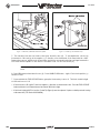
1. Remove the right side way cover for the X-axis to gain access to it's linear scale. Remove the front way
cover for the Y-axis to gain access to it's linear scale.
2. Access to the Z-axis linear scale is from the top of the machine. Removal of the head cover may be
necessary.
3. Tap the encoder head lightly and note any position change indicated by the control. If there is any change,
ensure that the encoder head/encoder bracket fasteners are tight.
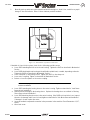
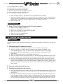
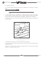
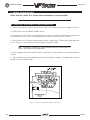
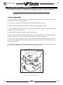
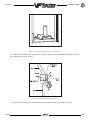
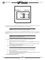
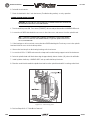
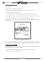
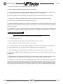
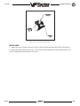
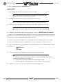
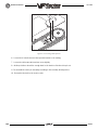
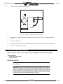
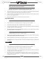
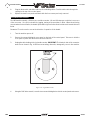
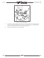
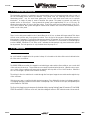
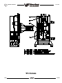
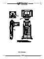
4. If problems persist, check for correct gaps at each end of travel by inserting tools T-1548 and T-1549
into their respective gaps, as shown in Figure 1-4. These tools must fit without having to force them. If the
tool can be moved more than 0.003", the fit is too loose.
Figure 1-4. Linear scale alignment check tools.
If the tools can be inserted in accordance with the above instructions, the linear scale is correctly aligned.
5. Check for flatness and parallelism of the linear scale(s) (with respect to the linear guide path) with a
magnetic base and indicator setup. It should be possible to insert the tools correctly at both ends of travel.
Runout specifications are:
Flatness:
Parallel:
0.005" along full travel
0.005" along full travel
6. Note results and contact Haas Automation for further instruction. DO NOT attempt to align the linear
scales.
96-8100
27
TROUBLESHOOTING
June 1998
1.10 AUTOMATIC PALLET CHANGER
´
Checking pallet repeatability on to the receiver.
l
l
l
l
l
´
Sticking Pallet.
l
l
´
Check for chips around the alignment pins or pallet clamp rail bushings.
Check the torque on the bolts that fasten the clamp rails to the pallet. If the bolts are loose
realign the pallet according to the instructions in the APC section of Mechanical Service.
APC not responding to controller commands.
l
l
28
Maximum tolerance is .+/-0005.
Pallets are not considered repeatable from one to the other. Pallets should use seperate
offsets.
If pallet is out of tolerance check the alignment pins on the receiver base and bushings on
the bottom side of the clamp rails for damage.
Check the height of the alignment pins on the receiver base, the top of the pin should be
.450 to .490 above the receiver base.
If the alignment pins are out of the receiver body, check the depth of the hole. Depth
should be .510 to .550.
If the APC does not run but the mill does, check the APC control cable.
Make sure the E-Stop jumper is removed and that the APC control cable is plugged into the
5th axis port tightly
96-8100
TROUBLESHOOTING
June 1998
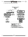
´
96-8100
Recovery from an E-Stop initiated during a pallet change
29
TROUBLESHOOTING
30
June 1998
96-8100
TROUBLESHOOTING
June 1998
1.11 ELECTRICAL TROUBLESHOOTING
CAUTION! Before working on any electrical components, power off the machine and wait
approximately 10 minutes. This will allow the high voltage power on the brushless amplifiers
to be discharged.
ELECTRICAL ALARMS
´
Axis Drive Fault Alarm
l
l
l
Blown amplifier - indicated by a light at bottom of amplifier when power is on. Replace amplifier.
Amplifier or MOCON is noise sensitive. If this is the case, the alarm can be cleared and the axis will
run normally for a while.
To check an amplifier, switch the motor leads and control cables between the amplifier and the one
next to it. If the same problem occurs with the other axis, the amplifier must be replaced. If the
problem stays on the same axis, either the MOCON or control cable. The problem could also be the
axis motor itself, with leads either shorted to each other or to ground, which is very rare.
Amplifier faulting out for valid reason, such as overtemp, overvoltage, or +/-12 volt undervoltage
condition. This usually results from running a servo intensive program, or unadjusted 12 volt power
supply. Replace amplifier.
Overvoltage could occur if regen load is not coming on, but this does not usually happen. The
problem could also be the axis motor itself, with leads either shorted to each other or to ground,
which is very rare.
´
Axis Overload
l
´
Phasing Error
l
´
The fuse function built into the MOCON has been overloaded, due to a lot of motor accel/decels, or
hitting a hard stop with the axis. This safety function protects the amplifier and motor, so find the
cause and correct it. If the current program is the cause, change the program. If the axis hits a hard
stop, the travel limits may be set wrong.
The MOCON did not receive the proper phasing information from the motors. DO NOT RESET the
machine if this alarm occurs. Power the machine down and back up. If the problem persists, it is
probably a broken wire or faulty MOCON connectors.
Servo Error Too Large
l
This alarms occurs when the difference between the commanded axis position and the actual
position becomes larger the the maximum that is set in the parameter.
This condition occurs when the amplifier is blown, is not receiving the commands, or the 320 volt
power source is dead. If the MOCON is not sending the correct commands to the amplifier, it is
probably due to a broken wire, or a PHASING ERROR that was generated.
´
Axis Z Fault or Z Channel Missing
l
96-8100
During a self-test, the number of encoder counts was found to be incorrect. This is usually caused
by a noisy environment, and not a bad encoder. Check all shields and grounds on the encoder cables
and the motor leads that come into the amplifiers. An alarm for one axis can be caused by a bad
grounding on the motor leads of another axis.
31
TROUBLESHOOTING
´
Axis Cable Fault
l
´
During a self-test, the encoder cable signals were found to be invalid. This alarm is usually caused
by a bad cable, or a bad connection on the motor encoder connectors. Check the cable for any
breaks, and the encoder connectors at the motor controller board. Machine noise can also cause this
alarm, although it is less common.
Alarm 101, "MOCON Comm. Failure"
l
´
June 1998
During a self-test of communications between the MOCON and main processor, the main processor
does not respond, and is suspected to be dead. This alarm is generated and the servos are stopped.
Check all ribbon cable connections, and all grounding. Machine noise can also cause this alarm,
although it is less common.
Alarm 157, "MOCON Watchdog Fault"
l
The self-test of the MOCON has failed. Replace the MOCON.
1.12 PROCESSOR STACK DIAGNOSTIC
(DISCONNECT CABLES FROM A NORMAL OPERATING SYSTEM)
´ Remove low voltage cable from the Video & Keyboard PCB
l
l
l
Processors LED's are normal
Runs fine and the CRT is Normal
No keypad beep
´ Remove low voltage cable from the MOTIF PCB
l
l
Processors LED's are normal then RUN goes out
No screen
´ Remove the Data & or Address buss from the Video & Keyboard PCB
l
Processors LED's Normal - then Run goes out
´ Remove the Data & or Address buss from the MOTIF PCB
l
Processors LED's Normal - then Run goes out
´ Remove the Data & or Address buss from the Micro Processor PCB
l
Processors LED's - CRT and Run are out
1.13 KEYBOARD DIAGNOSTIC
Note: Refer to the "Cable Locations" section of this manual for a drawing of the Keyboard Interface PCB.
32
96-8100
TROUBLESHOOTING
June 1998
The following is an example of how to troubleshoot the keypad:
Note: Keypad Diodes 1-24 correspond to chart numbers 1-24
Example
1. Pressing the RESET button will cause diodes 1 and 17 to conduct.
l With the POWER OFF read across diode 1.
l A typical reading is between .400-.700 ohms, note your reading.
2. Press and hold the RESET button. If the diode is conducting, the reading should drop about .03 ohms.
l (If your reading was .486 and it dropped to .460, for a difference of .026; the diode is good)
l The same will hold true for diode 17 in this example. If the reading stays the same or there is no
change, the diode is not conducting. Pull P2 and read between pins 1 and 17.
l Press and hold <RESET>. The meter should read a short (0 ohms) if not the keypad is bad.
96-8100
33
TROUBLESHOOTING
34
June 1998
96-8100
ALARMS
June 1998
2. ALARMS
Any time an alarm is present, the lower right hand corner of the screen will have a blinking "ALARM". Push the ALARM
display key to view the current alarm. All alarms are displayed with a reference number and a complete description.
If the RESET key is pressed, one alarm will be removed from the list of alarms. If there are more than 18 alarms, only
the last 18 are displayed and the RESET must be used to see the rest. The presence of any alarm will prevent the
operator from starting a program.
The ALARMS DISPLAY can be selected at any time by pressing the ALARM MESGS button. When there are no alarms,
the display will show NO ALARM. If there are any alarms, they will be listed with the most recent alarm at the bottom
of the list. The CURSOR and PAGE UP and PAGE DOWN buttons can be used to move through a large number of alarms.
The CURSOR right and left buttons can be used to turn on and off the ALARM history display.
The following alarm list shows the alarm numbers, the text displayed along with the alarm, and a detailed description
of the alarm, what can cause it, when it can happen, and how to correct it.
Alarm number and text:
Possible causes:
101
MOCON Comm. Failure
During a self-test of communications between the MOCON and main
processor, the main processor does not respond, and is suspected to be
dead. Check cable connections and grounding.
102
Servos Off
Indicates that the servo motors are off, the tool changer is disabled, the
coolant pump is off, and the spindle motor is stopped. Caused by EMERGENCY STOP, motor faults, tool changer problems, or power fail.
103
X Servo Error
Too Large
Too much load or speed on X-axis motor. The difference between the
motor position and the commanded position has exceeded a parameter.
The motor may also be stalled, disconnected, or the driver failed. The
servos will be turned off and a RESET must be done to restart. This alarm
can be caused by problems with the driver, motor, or the slide being run
into the mechanical stops.
104
Y Servo Error
Too Large
Z Servo Error
Too Large
A Servo Error
Too Large
same as 103.
105
106
107
Emergency Off
same as 103.
same as 103.
EMERGENCY STOP button was pressed. Servos are also turned off. After
the E-STOP is released, the RESET button must be pressed at least twice to
correct this; once to clear the E-STOP alarm and once to clear the Servo Off
alarm.
This alarm will also be generated if there is a low pressure condition in the
hydraulic counterbalance system. In this case, the alarm will not reset until
the condition has been corrected.
108
96-8100
X Servo Overload
Excessive load on X-axis motor. This can occur if the load on the motor
over a period of several seconds or even minutes is large enough to
exceed the continuous rating of the motor. The servos will be turned off
when this occurs. This can be caused by running into the mechanical
stops but not much past them. It can also be caused by anything
that causes a very high load on the motors.
35
ALARMS
36
June 1998
109
110
111
Y Servo Overload
Z Servo Overload
A Servo Overload
same as 108.
same as 108.
same as 108.
112
No Interrupt
Electronics fault. Call your dealer.
113
Shuttle In Fault
Tool changer not completely to right. During a tool changer operation
the tool in/out shuttle failed to get to the in position. Parameters 62 and
63 can adjust the time-out times. This alarm can be caused by anything
that jams the motion of the slide or by the presence of a tool in the
pocket facing the spindle. A loss of power to the tool changer can also
cause this, so check CB4, relays K9-K12, and fuse F1.
114
Shuttle Out Fault
Tool changer not completely to left. During a tool change operation the
tool in/out shuttle failed to get to the out position. Parameters 62 and
63 can adjust the time-out times. This alarm can be caused by anything
that jams the motion of the slide or by the presence of a tool in the
pocket facing the spindle. A loss of power to the tool changer can also
cause this, so check CB4, relays K9-K12, and fuse F1.
115
Turret Rotate Fault
Tool carousel motor not in position. During a tool changer operation the
tool turret failed to start moving or failed to stop at the right position.
Parameters 60 and 61 can adjust the time-out times. This alarm can be
caused by anything that jams the rotation of the turret. A loss of power
to the tool changer can also cause this, so check CB4, relays K9-K12, and
fuse F1.
116
Spindle Orientation Fault
Spindle did not orient correctly. During a spindle orientation function, the
spindle is rotated until the lock pin drops in; but the lock pin never
dropped. Parameters 66, 70, 73, and 74 can adjust the time-out times.
This can be caused by a trip of circuit breaker CB4, a lack of air pressure,
or too much friction with the orientation pin.
117
Spindle High Gear Fault
Gearbox did not shift into high gear. During a change to high gear, the
spindle is rotated slowly while air pressure is used to move the gears but
the high gear sensor was not detected in time. Parameters 67, 70 and 75
can adjust the time-out times. Check the air pressure, the solenoids circuit
breaker CB4, and the spindle drive.
118
Spindle Low Gear Fault
Gearbox did not shift into low gear. During a change to low gear, the spindle
is rotated slowly while air pressure is used to move the gears but the low
gear sensor was not detected in time. Parameters 67, 70 and 75 can adjust
the time-out times. Check the air pressure, the solenoids circuit breaker
CB4, and the spindle drive.
119
Over Voltage
Incoming line voltage is above maximum. The servos will be turned off and
the spindle, tool changer, and coolant pump will stop. If this condition
remains for 4.5 minutes, an automatic shutdown will begin.
120
Low Air Pressure
Air pressure dropped below 80 PSI for a period defined by Parameter 76.
The "Low Air Pr" alarm will appear on the screen as soon as the pressure
gets low, and this alarm appears after [Parameter 76] has elapsed. Check
your incoming air pressure for at least 100 PSI and ensure that the regulator
is set at 85 PSI.
96-8100
ALARMS
June 1998
96-8100
121
Low Lube or
Low Pressure
Way lube is low or empty or there is no lube pressure or too high a pressure.
Check tank at rear of mill and below control cabinet. Also check connector
on the side of the control cabinet. Check that the lube lines are not
blocked.
122
Regen Overheat
The control internal temperature is above 150 degrees F. This can be caused
by almost anything in the control overheating. But is usually caused by
overheat of the two regen resistors for servos and spindle drive. This alarm
will also turn off the servos, spindle drive, coolant pump, and tool changer.
One common cause of this overheat condition is an input line voltage too
high. If this condition remains for 4.5 minutes, an automatic shutdown will
begin.
123
Spindle Drive Fault
Overheat or failure of spindle drive or motor. The exact cause is indicated in the LED
window of the spindle drive inside the control cabinet. This can be caused by a stalled
motor, shorted motor, overvoltage, undervoltage, overcurrent, overheat of motor, or
drive failure.
124
Low Battery
Memory batteries need replacing within 30 days. This alarm is only generated at
power on and indicates that the 3.3 volt Lithium battery is below 2.5 volts. If this is
not corrected within about 30 days, you may lose your stored programs, parameters,
offsets, and settings.
125
Shuttle fault
Tool shuttle not initialized at power on, CYCLE START or spindle motion command.
This means that the tool shuttle was not fully retracted to the Out position.
126
Gear Fault
Gearshifter is out of position when a command is given to rotate the spindle. This
means that the two speed gear box is not in either high or low gear but is somewhere
in between. Check the air pressure, the solenoids circuit breaker CB4, and the
spindle drive.
127
No Turret Mark
Tool carousel motor not in position. The turret motor only stops in one position
indicated by a switch and cam on the Geneva mechanism. This alarm is only
generated at power-on. The AUTO ALL AXES button will correct this but be sure that
the pocket facing the spindle afterwards does not contain a tool.
129
M Fin Fault
M-Fin was active at power on. Check the wiring to your M code interfaces. This test
is only performed at power-on.
130
Tool Unclamped
The tool appeared to be unclamped during spindle orientation, a gear change, a
speed change, or TSC start-up. The alarm will also be generated if the tool
release piston is energized during Power Up. This can be caused by a fault in the
air solenoids, relays on the I/O assembly, the drawbar assembly, or in the wiring.
131
Tool Not Clamped
When clamping or powering up the machine, the Tool Release Piston is not
HOME. This is a possible fault in the air solenoids, relays on the IO Assembly, the
drawbar assembly, or wiring.
132
Power Down Failure
Machine did not turn off when an automatic power-down was commanded. Check
wiring to POWIF card on power supply assembly, relays on the IO assembly, and the
main contactor K1.
37
ALARMS
38
June 1998
133
Spindle Locked
Shot pin did not release. This is detected when spindle motion is commanded.
Check the solenoid that controls the air to the lock, relay 2-8, the wiring to the sense
switch, and the switch.
134
Tool Clamp Fault
When UNCLAMPING the tool did not release from spindle when commanded. Check
air pressure and solenoid circuit breaker CB4. Can also be caused by misadjustment
of drawbar assembly.
135
X Motor Over Heat
Servo motor overheat. The temperature sensor in the motor indicates over 150
degrees F. This can be caused by an extended overload of the motor such as leaving
the slide at the stops for several minutes.
136
137
138
Y Motor Over Heat
Z Motor Over Heat
A Motor Over Heat
same as 135.
same as 135.
same as 135.
139
X Motor Z Fault
Encoder marker pulse count failure. This alarm usually indicates that the encoder has
been damaged and encoder position data is unreliable. This can also be caused by
loose connectors at P1-P4.
140
141
142
Y Motor Z Fault
Z Motor Z Fault
A Motor Z Fault
same as 139.
same as 139.
same as 139.
143
Spindle Not Locked
Shot pin not fully engaged when a tool change operation is being performed.
Check air pressure and solenoid circuit breaker CB4. This can also be caused by a fault
in the sense switch that detects the position of the lock pin.
144
Time-outCall Your Dealer
Time allocated for use prior to payment exceeded. Call your dealer.
145
X Limit Switch
Axis hit limit switch or switch disconnected. This is not normally possible as the
stored stroke limits will stop the slides before they hit the limit switches. Check the
wiring to the limit switches and connector P5 at the side of the main cabinet. Can also
be caused by a loose encoder shaft at the back of the motor or coupling of motor to
the screw.
146
147
Y Limit Switch
Z Limit Switch
same as 145
same as 145
148
A Limit Switch
Normally disabled for rotary axis.
149
Spindle Turning
Spindle not at zero speed for tool change. A signal from spindle drive indicating that
the spindle drive is stopped is not present while a tool change operation is going on.
150
Z and Tool
Interlocked
Changer not at home and either the Z or A or B axis (or any combination) is not
at zero. If RESET, E-STOP, or POWER OFF occurs during tool change, Z-axis motion
and tool changer motion may not be safe. Check the position of the tool changer and
remove the tool if possible. Re-initialize with the AUTO ALL AXES button but be sure
that the pocket facing the spindle afterwards does not contain a tool.
96-8100
ALARMS
June 1998
151
Low Thru Spindle
Coolant
For machines with Through the Spindle Coolant only. This alarm will shut off the
spindle, feed, and pump all at once. It will turn on purge, wait for the amount of time
specified in parameter 237 for the coolant to purge, and then turn off the purge. Check
for low coolant tank level, any filter or intake strainer clogging, or for any kinked or
clogged coolant lines. If no problems are found with any of these, and none of the
coolant lines are clogged or kinked, call your dealer.
152
Self Test Fail
Control has detected an electronics fault. All motors and solenoids are shut down.
This is most likely caused by a fault of the processor board stack at the top left of
the control. Call your dealer.
153
X-axis Z
Ch Missing
Broken wires or encoder contamination. All servos are turned off. This
can also be caused by loose connectors at P1-P4.
154
Y-axis Z
Ch Missing
Z-axis Z
Ch Missing
A-axis Z
Ch Missing
same as 153.
157
MOCON Watchdog
Fault
The self-test of the MOCON has failed. Replace the MOCON.
158
Video/Keyboard
PCB Failure
Internal circuit board problem. The VIDEO PCB in the processor stack is
tested at power-on. This could also be caused by a short in the front panel membrane
keypad. Call your dealer.
159
Keyboard Failure
Keyboard shorted or button pressed at power on. A power-on test of the membrane
keypad has found a shorted button. It can also be caused by a short in the cable from
the main cabinet or by holding a switch down during power-on.
160
Low Voltage
The line voltage to control is too low. This alarm occurs when the AC line voltage
drops below 190 when wired for 230 volts or drops below 165 when wired for 208
volts.
161
X-Axis Drive Fault
Current in X servo motor beyond limit. Possibly caused by a stalled or overloaded
motor. The servos are turned off. This can be caused by running a short distance into
a mechanical stop. It can also be caused by a short in the motor or a short of one motor
lead to ground.
162
Y-Axis Drive Fault
same as 161.
163
Z-Axis Drive Fault
same as 161.
164
A-Axis Drive Fault
same as 161.
165
X Zero Ret
Margin Too Small
This alarm will occur if the home/limit switches move or are misadjusted.
This alarm indicates that the zero return position may not be consistent from one zero
return to the next. The encoder Z channel signal must occur between 1/8 and 7/8
revolution of where the home switch releases. This will not turn the servos off but
will stop the zero return operation.
155
156
96-8100
same as 153.
same as 153.
39
ALARMS
40
June 1998
166
Y Zero Ret
Margin Too Small
Same as 165.
167
Z Zero Ret
Margin Too Small
Same as 165.
168
A Zero Ret
Margin Too Small
Not normally enabled for A-axis.
169
Spindle Direction
Fault
Problem with rigid tapping hardware. The spindle started turning in the
wrong direction.
170
Phase Loss
171
UNUSED
172
UNUSED
173
Spindle Ref
Signal Missing
The Z channel pulse from the spindle encoder is missing for hard tapping
synchronization.
174
Tool Load Exceeded
The tool load monitor option is selected and the maximum load for a tool
was exceeded in a feed. This alarm can only occur if the tool load
monitor function is installed in your machine.
175
Ground Fault Detected
A ground fault condition was detected in the 115V AC supply. This can
be caused by a short to ground in any of the servo motors, the tool
change motors, the fans, or the oil pump.
176
Over Heat Shutdown
An overheat condition persisted for 4.5 minutes and caused an automatic
shutdown.
177
Over Voltage Shutdown
An overvoltage condition persisted for 4.5 minutes and caused an
automatic shutdown.
178
Divide by Zero
Software Error; Call your dealer.
179
Low Pressure
Transmission Oil
Spindle coolant oil is low or low pressure condition in lines.
180
Pallet Not Clamped
The APC pallet changer was not completed for some reason (pressing Estop, reset, or feedhold), and an attempt was made to run the spindle. Run
M50 pallet change to reset the machine.
182
X Cable Fault
Cable from X-axis encoder does not have valid differential signals.
183
184
185
Y Cable Fault
Z Cable Fault
A Cable Fault
Same as 182.
Same as 182.
Same as 182.
186
Spindle Not Turning
Status from spindle drive indicates it is not at speed when expected.
187
B Servo Error Too Large
Same as 103.
Problem with incoming line voltage between legs L1 and L2. This usually
indicates that there was a transient loss of input power to the machine.
96-8100
ALARMS
June 1998
96-8100
188
189
190
191
192
193
194
B Servo Overload
B Motor Overheat
B Motor Z Fault
B Limit Switch
B Axis Z Ch Missing
B Axis Drive Fault
B Zero Ret Margin
Too Small
Same as 108.
Same as 135.
Same as 139.
Same as 148.
Same as 153.
Same as 161.
Same as 168.
195
B Cable Fault
Same as 182.
196
Coolant Spigot Failure
Spigot failed to achieve commanded location after two (2) attempts.
197
100 Hours Unpaid Bill
Call your dealer.
198
Precharge Failure
During TSC operation, the precharge failed for greater than 0.1 seconds.
It will shut off the feed, spindle and pump all at once. If received, check
all air lines and the air supply pressure.
199
Negative RPM
A negative spindle RPM was sensed.
201
Parameter CRC Error
Parameters lost maybe by low battery. Check for a low battery and low
battery alarm.
202
Setting CRC Error
Settings lost maybe by low battery. Check for a low battery and low
battery alarm.
203
Lead Screw CRC Error
Lead screw compensation tables lost maybe by low battery. Check for
CRC Error low battery and low battery alarm.
204
Offset CRC Error
Offsets lost maybe by low battery. Check for a low battery and low
battery alarm.
205
Programs CRC Error
Users program lost maybe by low battery. Check for a low battery and
low battery alarm.
206
Internal Program Error
Possible corrupted program. Save all programs to floppy disk, delete all, then
reload. Check for a low battery and low battery alarm.
207
Queue Advance Error
Software Error; Call your dealer.
208
Queue Allocation Error
Software Error; Call your dealer.
209
Queue Cutter
Comp Error
Software Error; Call your dealer.
210
Insufficient Memory
Not enough memory to store users program. Check the space available
in the LIST PROG mode and possibly delete some programs.
211
Odd Prog Block
Possible corrupted program. Save all programs to floppy disk, delete all, then
reload.
212
Program Integrity Error
Possible corrupted program. Save all programs to floppy disk, delete all, then
reload. Check for a low battery and low battery alarm.
41
ALARMS
42
June 1998
213
Program RAM CRC Error
Electronics fault; Call your dealer.
214
No. of Programs
Changed
Indicates that the number of programs disagrees with the internal
variable that keeps count of the loaded programs. Call your dealer.
215
Free Memory PTR
Changed
Indicates the amount of memory used by the programs counted in the
system disagrees with the variable that points to free memory. Call your
dealer.
217
X Axis Phasing Error
Error occurred in phasing initialization of brushless motor. This can be
caused by a bad encoder, or a cabling error.
218
219
220
221
222
Y Axis Phasing Error
Z Axis Phasing Error
A Axis Phasing Error
B Axis Phasing Error
C Axis Phasing Error
Same as above.
Same as above.
Same as above.
Same as above.
Same as above.
223
Door Lock Failure
In machines equipped with safety interlocks, this alarm occurs when the
control senses the door is open but it is locked. Check the door lock circuit.
224
X Transition Fault
Illegal transition of count pulses in X axis. This alarm usually indicates that
the encoder has been damaged and encoder position data is unreliable.
This can also be caused by loose connectors at the MOCON or MOTIF PCB.
225
226
227
228
229
Y
Z
A
B
C
Same as above.
Same as above.
Same as above.
Same as above.
Same as above.
231
Jog Handle Transition
Fault
Same as 224.
232
Spindle Transition Fault
Same as 224.
233
Jog Handle Cable Fault
Cable from jog handle encoder does not have valid differential signals.
234
Spindle Enc. Cable Fault
Cable from spindle encoder does not have valid differential signals.
235
Spindle Z Fault
Same as 139.
236
Spindle Motor Overload
This alarm is generated in machines equipped with a Haas vector drive, if the
spindle motor becomes overloaded.
237
Spindle Following Error
The error between the commanded spindle speed and the actual speed has
exceeded the maximum allowable (as set in Parameter 184).
240
Empty Prog or No EOB
DNC program not found, or no end of program found.
241
Invalid Code
RS-232 load bad. Data was stored as comment. Check the program being
received.
242
No End
Check input file for a number that has too many digits
Transition
Transition
Transition
Transition
Transition
Fault
Fault
Fault
Fault
Fault
96-8100
ALARMS
June 1998
96-8100
243
Bad Number
Data entered is not a number.
244
Missing )
Comment must end with a " ) ".
245
Unknown Code
Check input line or data from RS-232. This alarm can occur while editing
data into a program or loading from RS-232.
246
String Too Long
Input line is too long. The data entry line must be shortened.
247
Cursor Data Base Error
Software Error; Call your dealer.
248
Number Range Error
Number entry is out of range.
249
Prog Data
Begins Odd
Possible corrupted program. Save all programs to floppy disk, delete all,
then reload.
250
251
252
Program Data Error
Prog Data Struct Error
Memory Overflow
Same as 249.
Same as 249.
Same as 249.
253
Electronics Overheat
The control box temperature has exceeded 145 degrees F. This can be
caused by an electronics problem, high room temperature, or clogged air
filter.
254
Spindle Overheat
This alarm is only generated in machines equipped with a Haas vector
drive. The spindle temperature sensor sensed a high temperature for greater
than 1.5 seconds.
257
Program Data Error
Same as 249.
258
Invalid DPRNT Format
Macro DPRNT statement not structured properly.
259
Bad Language Version
Call your dealer.
260
Bad Language CRC
Indicates FLASH memory has been corrupted or damaged.
261
Rotary CRC Error
Rotary table saved parameters (used by Settings 30, 78) have a CRC error.
Indicates a loss of memory - call your dealer.
262
Parameter CRC Missing
RS-232 or floppy read of parameter had no CRC when loading from floppy
or RS-232.
263
Lead Screw CRC Missing
Lead screw compensation tables have no CRC when loading from floppy or
RS-232.
264
Rotary CRC Missing
Rotary table parameters have no CRC when loading from floppy or RS-232.
265
268
Macro Variable File
CRC Error
Door open @ M95 Start
Macro variable file has a CRC error. Indicates a loss of memory.
Call your dealer.
Generated whenever an M95 (Sleep Mode) is encountered and the door is
open. The door must be closed in order to start sleep mode
270
C Servo Error Too Large
Same as 103.
43
ALARMS
44
June 1998
271
272
273
274
275
C Servo Overload
C Motor Overheat
C Motor Z Fault
C Limit Switch
C Axis Z Ch Missing
Same as 108.
Same as 135.
Same as 139.
Same as 145.
Same as 153.
276
C Axis Drive Fault
Same as 161.
277
C Zero Ret Margin
Too Small
Same as 165.
278
C Cable Fault
Same as 182.
279
X Axis Linear Scale
Z Fault
Encoder marker pulse count failure. This alarm usually indicates that the
encoder has been damaged and encoder position data is unreliable. This
can also be caused by loose connectors at P1-P4.
280
Y Axis Linear Scale
Z Fault
Same as alarm 279.
281
Z Axis Linear Scale
Z Fault
Same as alarm 279.
282
A Axis Linear Scale
Z Fault
Same as alarm 279.
283
X Axis Linear Scale
Z Channel Missing
Broken wires or encoder contamination. All servos are turned off. This
can also be caused by loose connectors at P1-P4.
284
Y Axis Linear Scale
Z Channel Missing
Same as alarm 283.
285
Z Axis Linear Scale
Z Channel Missing
Same as alarm 283.
286
A Axis Linear Scale
Z Channel Missing
Same as alarm 283.
287
X Axis Linear Scale
Cable Fault
Cable from X-axis encoder does not have valid differential signals.
288
Y Axis Linear Scale
Cable Fault
Same as alarm 287.
289
Z Axis Linear Scale
Cable Fault
Same as alarm 287.
290
A Axis Linear Scale
Cable Fault
Same as alarm 287.
291
Low Air Volume/Pressure
During ATC
An automatic tool change was not completed due to insufficient volume or
pressure of compressed air. Check air supply line.
302
Invalid R In G02 or G03
Check your geometry. R must be less than or equal to half the distance from
start to end within an accuracy of 0.0010 inches.
96-8100
ALARMS
June 1998
96-8100
303
Invalid X, Y, or Z In
G02 or G03
Check your geometry.
304
Invalid I, J, or K In
G02 or G03
Check your geometry. Radius at start must match radius at end of arc within
0.0010 inches.
305
Invalid Q In
Canned Cycle
Q in a canned cycle must be greater than zero.
306
Invalid I, J, K, or Q In
Canned Cycle
I, J, K, and Q in a canned cycle must be greater than zero.
307
Subroutine
Nesting Too Deep
Subprogram nesting is limited to nine levels. Simplify your program.
309
Exceeded Max Feed Rate
Use a lower feed rate.
310
Invalid G Code
G code not defined and is not a macro call.
311
Unknown Code
Possible corruption of memory by low battery. Call your dealer.
312
Program End of subroutine reached before M99. Need an M99 to return from subroutine.
313
No P Code In M97,
M98, or G65
Must put subprogram number in P code.
314
Subprogram or Macro
Not In Memory
Check that a subroutine is in memory or that a macro is defined.
315
Invalid P Code In
M97, M98 or M99
The P code must be the name of a program stored in memory without a
decimal point for M98 and must be a valid N number for M99.
316
X Over Travel Range
X-axis will exceed stored stroke limits. This is a parameter in negative
direction and is machine zero in the positive direction. This will only
occur during the operation of a user's program.
317
318
Y Over Travel Range
Z Over Travel Range
same as 316.
same as 316.
319
A Over Travel Range
Not normally possible with A-axis.
320
No Feed Rate Specified
Must have a valid F code for interpolation functions.
321
Auto Off Alarm
A fault turned off the servos automatically; occurs in debug mode only.
322
Sub Prog Without M99
Add an M99 code to the end of program called as a subroutine.
324
Delay Time Range Error
P code in G04 is greater than or equal to 1000 seconds (over 999999
milliseconds).
325
Queue Full
Control problem; call your dealer.
326
G04 Without P Code
Put a Pn.n for seconds or a Pn for milliseconds.
45
ALARMS
46
June 1998
327
No Loop For M
Code Except M97, M98
L code not used here. Remove L Code.
328
Invalid Tool Number
Tool number must be between 1 and the value in Parameter 65.
329
Undefined M Code
That M code is not defined and is not a macro call.
330
Undefined Macro Call
Macro name O90nn not in memory. A macro call definition is in parameters
and was accessed by user program but that macro was not loaded into
memory.
331
Range Error
Number too large.
332
H and T
Not Matched
This alarm is generated when Setting 15 is turned ON and an H code
number in a running program does not match the tool number in the
spindle. Correct the Hn codes, select the right tool, or turn off Setting 15.
333
X-Axis Disabled
Parameters have disabled this axis. Not normally possible in VF Series
CNC Mill.
334
335
Y-Axis Disabled
Z-Axis Disabled
same as 333.
same as 333.
336
A-Axis Disabled
An attempt was made to program the A-axis while it was disabled
(DISABLED bit in Parameter 43 set to 1).
337
Line Referenced By
P, Not Found
Subprogram is not in memory, or P code is incorrect.
338
Invalid IJK and XYZ
in G02 or G03
There is a problem with circle definition; check your geometry.
339
Multiple Codes
Only one M, X, Y, Z, A, Q, etc. allowed in any block or two G codes in the same
group.
340
Cutter Comp Begin
With G02 or G03
Select cutter compensation earlier. Cutter comp. must begin on a linear
move.
341
Cutter Comp End
With G02 or G03
Disable cutter comp later.
342
Cutter Comp Path
Too Small
Geometry not possible. Check your geometry.
343
Display Queue
Record Full
A block exists that is too long for displaying queue. Shorten title block.
344
Cutter Comp With
G18 and G19
Cutter comp only allowed in XY plane (G17).
345
Diff Step Ratio
On G17 Plane
Parameters 5 and 19 must be same value.
346
Diff Step Ratio
On G18 Plane
Parameters 5 and 33 must be same value.
96-8100
ALARMS
June 1998
96-8100
347
Diff Step Ratio
On G19 Plane
Parameters 19 and 33 must be same value.
348
Motion Not Allowed
In G93 Mode
This alarm is generated if the mill is in Inverse Time Feed mode, and a
G12, G13, G70, G71, G72, G150, or any Group 9 motion command is issued.
349
Prog Stop W/O
Cancel Cutter Comp
Cutter compensation has been cancelled without an exit move. Potential
damage to part.
350
Cutter Comp Look
Ahead Error
There are too many non-movement blocks between motions when cutter
comp is being used. Remove some intervening blocks.
351
Invalid P Code
In a block with G103 (Block Lookahead Limit), a value between 0 and 15
must be used for the P code.
352
Aux Axis Power Off
Aux B, C, U, V, or W axis indicate servo off. Check auxiliary axes.
Status from control was OFF.
353
Aux Axis No Home
A ZERO RET has not been done yet on the aux axes. Check auxiliary
axes. Status from control was LOSS.
354
Aux Axis
Disconnected
Aux axes not responding. Check auxiliary axes and RS-232 connections.
355
Aux Axis Position
Mismatch
Mismatch between machine and aux axes position. Check aux axes and
interfaces. Make sure no manual inputs occur to aux axes.
356
Aux Axis Travel Limit
Aux axes are attempting to travel past their limits.
357
Aux Axis Disabled
Aux axes are disabled.
358
Multiple Aux Axis
Can only move one auxiliary axis at a time.
359
Invalid I, J, or K In G12
or G13
Check your geometry.
360
Tool Changer Disabled
Check Parameter 57. Not a normal condition for VF Series CNC Mill.
361
Gear Change Disabled
Check Parameter 57. Not a normal condition for VF Series CNC Mill.
362
Tool Usage Alarm
Tool life limit was reached. To continue, reset the usage count in the
Current Commands display and press RESET.
363
Coolant Locked Off
Override is off and program tried to turn on coolant.
364
No Circ Interp
Aux Axis
Only rapid or feed is allowed with aux axes.
367
Cutter Comp
Interference
G01 cannot be done with tool size.
368
Groove Too Small
Tool too big to enter cut.
47
ALARMS
48
June 1998
369
Tool Too Big
Use a smaller tool for cut.
370
Pocket Definition
Error
Check geometry for G150.
371
Invalid I, J, K, OR Q
Check G150.
372
Tool Change In
Canned Cycle
Tool change not allowed while canned cycle is active.
373
Invalid Code in DNC
A code found in a DNC program could not be interpreted because of
restrictions to DNC.
374
Missing XYZA in
G31 or G36
G31 skip function requires an X, Y, Z, or A move.
375
Missing Z or H in G37
G37 automatic tool length measurement function requires H code, Z value,
and tool offset enabled. X, Y, and A values not allowed.
376
No Cutter Comp In Skip
SkipG31 and G37 functions cannot be used with cutter compensation.
377
No Skip in Graph/Sim
Graphics mode cannot simulate skip function.
378
Skip Signal Found
Skip signal check code was included but skip was found when it was not
expected.
379
Skip Signal Not Found
Skip signal check code was included but skip was not found when it was
expected.
380
X, Y, A, or G49
Not Allowed in G37
G37 may only specify Z-axis and must have tool offset defined.
381
G43 or G44 Not
Allowed in G36 or G136
Auto work offset probing must be done without tool offset.
382
D Code Required in G35
A Dnn code is required in G35 in order to store the measured tool diameter.
383
Inch Is Not Selected
G20 was specified but settings have selected metric input.
384
Metric Is Not Selected
G21 was specified but settings have selected inches.
385
Invalid L, P, or R
Code In G10
G10 was used to changes offsets but L, P, or R code is missing or
invalid.
386
Invalid Address Format
An address A...Z was used improperly.
387
Cutter Comp Not
Allowed With G103
If block buffering has been limited, Cutter comp cannot be used.
388
Cutter Comp Not
Allowed With G10
Coordinates cannot be altered while cutter comp is active. Move G10
outside of cutter comp enablement.
389
G17, G18, G19
Illegal in G68
Planes of rotation cannot be changed while rotation is enabled.
96-8100
ALARMS
June 1998
96-8100
390
No Spindle Speed
S code has not been encountered. Add an S code.
391
Feature Disabled
An attempt was made to use a control feature not enabled by a parameter
bit. Set the parameter bit to 1.
392
B Axis Disabled
Same as 336.
393
Invalid Motion In
G74 or G84
Rigid Tapping can only be in the Z minus G74 or G84 direction.
Make sure that the distance from the initial position to the commanded Z
depth is in the minus direction.
394
B Over Travel Range
Same as 316.
395
No G107 Rotary Axis
Specified
A rotary axis must be specified in order to perform cylindrical mapping
(G107).
396
Invalid G107 Rotary
Axis Specified
The rotary axis specified is not a valid axis, or has been disabled.
397
Aux Axis In G93 Block
This alarm is generated if a G-code block specifies any form of interpolated
motion that involves BOTH one or more of the regular axes (X, Y, Z, A, B,
etc...) AND one or more of the auxiliary axes (C, U, V, W).
398
Aux Axis Servo Off
Aux. axis servo shut off due to a fault.
403
RS-232 Too Many Progs
Cannot have more than 200 programs in memory.
404
RS-232 No Program
Name
Need name in programs when receiving ALL; otherwise has no way to
store them.
405
RS-232 Illegal Prog
Name
Check files being loaded. Program name must be Onnnn and must be
at beginning of a block.
406
RS-232 Missing Code
A receive found bad data. Check your program. The program will be
stored but the bad data is turned into a comment.
407
RS-232 Invalid Code
Check your program. The program will be stored but the bad data is
turned into a comment.
408
RS-232 Number Range
Error
Check your program. The program will be stored but the bad data is
turned into a comment.
409
RS-232 Invalid N Code
Bad Parameter or Setting data. User was loading settings or parameters
and something was wrong with the data.
410
RS-232 Invalid V Code
Bad parameter or setting data. User was loading settings or parameters
and something was wrong with the data.
411
RS-232 Empty Program
Check your program. Between % and % there was no program found.
412
RS-232 Unexpected
End of Input
Check Your Program. An ASCII EOF code was found in the input data
before program receive was complete. This is a decimal code 26.
49
ALARMS
50
June 1998
413
RS-232 Load
Insufficient Memory
Program received doesnt fit. Check the space available in the LIST PROG
mode and possibly delete some programs.
414
RS-232 Buffer Overflow
Data sent too fast to CNC. This alarm is not normally possible as this
control can keep up with even 38400 bits per second.
415
RS-232 Overrun
Data sent too fast to CNC. This alarm is not normally possible as this
control can keep up with as much as 38400 bits per second.
416
RS-232 Parity Error
Data received by CNC has bad parity. Check parity settings, number of
data bits and speed. Also check your wiring.
417
RS-232 Framing Error
Data received was garbled and proper framing bits were not found. One
or more characters of the data will be lost. Check parity settings,
number of data bits and speed.
418
RS-232 Break
Break condition while receiving. The sending device set the line to a break
condition. This might also be caused by a simple break in the cable.
419
Invalid Function
For DNC
A code found on input of a DNC program could not be interpreted.
420
Program Number
Mismatch
The O code in the program being loaded did not match the O code
entered at the keyboard. Warning only.
429
Flpy Dir Insufficient
Memory
Floppy memory was almost full when an attempt was made to read the
floppy directory.
430
Floppy Unexpected
End of Input
Check your program. An ASCII EOF code was found in the input data
before program receive was complete. This is a decimal code 26.
431
Floppy No Prog
Name
Need name in programs when receiving ALL; otherwise has no way to
store them.
432
Floppy Illegal Prog
Name
Check files being loaded. Program must be Onnnn and must be at the
beginning of a block.
433
Floppy Empty Prog
Name
Check your program. Between % and % there was no program found.
434
Floppy Load Insufficient
Memory
Program received doesn't fit. Check the space available in the LIST
PROG mode and possibly delete some programs.
435
Floppy Abort
Could not read disk.
436
Floppy File Not Found
Could not find floppy file.
501
Too Many Assignments
In One Block
Only one assignment = is allowed per block. Divide block in error into
multiple blocks.
502
[ Or = Not First Term
In Expressn
An expression element was found where it was not preceded by [ or
=, that start expressions.
96-8100
ALARMS
June 1998
96-8100
503
Illegal Macro Variable
Reference
A macro variable number was used that is not supported by this control,
use another variable.
504
Unbalanced Paren. In
Expression
Unbalanced brackets, [ or ], were found in an expression. Add or
delete a bracket.
505
Value Stack Error
The macro expression value stack pointer is in error. Call your dealer.
506
Operand Stack Error
The macro expression operand stack pointer is in error. Call your dealer.
507
Too Few Operands On
Stack
An expression operand found too few operands on the expression stack.
Call your dealer.
508
Division By Zero
A division in a macro expression attempted to divide by zero.
Re-configure expression.
509
Illegal Macro
Variable Use
See "Macros" section for valid variables.
510
Illegal Operator or
Function Use
See "Macros" section for valid operators.
511
Unbalanced Right
Brackets
Number of right brackets not equal to the number of left brackets.
512
Illegal Assignment Use
Attempted to write to a read-only macro variable.
513
Var. Ref. Not Allowed
With N Or O
Alphabetic addresses N and O cannot be combined with macro variables.
Do not declare N#1, etc.
514
Illegal Macro Address
Reference
A macro variable was used incorrectly with an alpha address. Same as
513.
515
Too Many Conditionals
In a Block
Only one conditional expression is allowed in any WHILE or IF-THEN
block.
516
Illegal Conditional
Or No Then
A conditional expression was found outside of an IF-THEN, WHILE,
or M99 block.
517
Exprsn. Not Allowed
With N Or O
A macro expression cannot be concatenated to N or O. Do not declare
O[#1], etc.
518
Illegal Macro Exprsn
Reference
An alpha address with expression, such as A[#1+#2], evaluated
incorrectly. Same as 517.
519
Term Expected
In the evaluation of a macro expression an operand was expected and
not found.
520
Operator Expected
In the evaluation of a macro expression an operator was expected and
not found.
521
Illegal Functional
Parameter
An illegal value was passed to a function, such as SQRT[ or ASIN[.
51
ALARMS
52
June 1998
522
Illegal Assignment
Var Or Value
A variable was referenced for writing. The variable referenced is read
only.
523
Conditional Reqd
Prior To THEN
THEN was encountered and a conditional statement was not processed
in the same block.
524
END Found With No
Matching DO
An END was encountered without encountering a previous matching
DO. DO-END numbers must agree.
525
Var. Ref. Illegal
During Movement
Variable cannot be read during axis movement.
526
Command Found On
DO/END Line
A G-code command was found on a WHILE-DO or END macro block.
Move the G-code to a separate block.
527
= Not Expected Or
THEN Required
Only one Assignment is allowed per block, or a THEN statement is missing.
528
Parameter Precedes
G65
On G65 lines all parameters must follow the G65 G-code. Place
parameters after G65.
529
Illegal G65 Parameter
The addresses G, L, N, O, and P cannot be used to pass parameters.
530
Too Many I, J, or Ks
In G65
Only 10 occurrences of I, J, or K can occur in a G65 subroutine call.
Reduce the I, J, or K count.
531
Macro Nesting Too
Deep
Only four levels of macro nesting can occur. Reduce the amount of
nested G65 calls.
532
Unknown Code In
Pocket Pattern
Macro syntax is not allowed in a pocket pattern subroutine.
533
Macro Variable
Undefined
A conditional expression evaluated to an UNDEFINED value, i.e. #0.
Return True or False.
534
DO Or END Already
In Use
Multiple use of a DO that has not been closed by and END in the same
subroutine. Use another DO number.
535
Illegal DPRNT
Statement
A DPRNT statement has been formatted improperly, or DPRNT does
not begin block.
536
Command Found On
DPRNT Line
A G-code was included on a DPRNT block. Make two separate blocks.
537
RS-232 Abort
On DPRNT
While a DPRNT statement was executing, the RS-232 communications
failed.
538
Matching END Not
Found
A WHILE-DO statement does not contain a matching END statement.
Add the proper END statement.
539
Illegal Goto
Expression after "GOTO" not valid.
96-8100
ALARMS
June 1998
540
Macro Syntax
Not Allowed
A section of code was interpreted by the control where macro statement
syntax is not permitted.
613
Command Not Allowed
In Cutter Comp.
A command (M96, for example) in the highlighted block cannot be
executed while cutter comp. is invoked.
End Of List
Note: Alarms 1000-1999 are user defined by macro programs.
1002 Unclamp Error
1003 Clamp Error
The pallet did not unclamp in the amount of time allowed. This can be caused
by a bad air solenoid, a blocked or cinked air line, or a mechanical problem.
The pallet did not clamp in the amount of time allowed by the M50
macro. This alarm is most likely caused by the VMC table not being in
the correct position. This can be adjusted using the macro variables for
the X position (#500, 504) as described in the "Installation" section. If
the pallet is in the correct position but not clamped, push the pallet
against the hard stop and run an M18.
If the pallet is clamped, but not correctly, run an M17 to unclamp, push
the pallet to the correct position, and run an M18 to clamp the pallet.
Less common causes could be that the slip clutch is slipping, the motor
is at fault, an air solenoid is bad, or an air line is blocked or kinked.
96-8100
1004
Mislocated Pallet @ APC
A pallet is not in the proper place on the APC. The pallet must be pushed
back against the hard stop by hand.
1005
Pal No Conflict Rec & Ch
(Pallet Number Conflict Receiver and Pallet Changer)
The incorrect pallet number is entered in macro variable #510. Run an
M50 to reset this variable.
1006
Switch Missed Pal 1
Pallet #1 did not return from the receiver to the APC in the allowable
amount of time. This can be caused by the chain switch block missing
the limit switch, or from another mechanical problem, such as clutch
slippage.
1007
Switch Missed Pal 2
Pallet #2 did not return from the receiver to the APC in the allowable
amount of time. This can be caused by the chain switch block missing
the limit switch, or another mechanical problem, such as clutch slip
page.
1008
Door Not Open
The automatic door did not open (in the allowable time) when necessary
to perform an APC function. This can be caused by a bad air solenoid,
a blocked or kinked air line, or a mechanical problem.
1009
Door Not Closed
The automatic door did not close (in the allowable time) when necessary
after an APC function has been performed. This can be caused by a bad
air solenoid, a blocked or kinked air line, or a mechanical problem.
53
ALARMS
1010
June 1998
Missing Pallet @ Receiver
1011 Unknown Chain Location
Pallet change sequence was halted because receiver switch was not
activated. Pallet is either unclamped or not on the receiver. Ensure the
pallet is correctly located on receiver (against hardstop) then run M18
to clamp the pallet.
Neither Chain Location switch is tripped, so the control cannot locate
the chain position. This can occur if a pallet change is interrupted for
any reason, such as an alarm or an E-STOP. To correct this problem, the
pallets and chain must be moved back into a recognized position, such
as both pallets home or one pallet home and one on the receiver. The
chain position adjustment tool must be used to rotate the chain into
position. The pallets must be pushed into place by hand.
WARNING! Do not move the limit switches for any reason.
CAUTION! The pallets weigh 300 lbs. each, and can cause serious injury. Use extreme
caution when moving them.
1012 Incorrect Chain Location
Chain not in position to load or unload pallets when necessary. To
correct this, the mislocated pallet must be moved back into the proper
position by hand.
CAUTION! The pallets weigh 300 lbs. each, and can cause serious injury. Use extreme
caution when moving them.
54
96-8100
MECHANICAL SERVICE
January 1998
MECHANICAL SERVICE
RECOMMENDED TORQUE VALUES FOR MACHINE FASTENERS
The following chart should be used as a reference guide for torquing machine fasteners where specified.
DIAMETER
TORQUE
1/4 - 20
5/16 - 18
3/8 - 16
M10 - 100
M12 - 65
1/2 - 13
3/4 - 10
1-8
15 ft. lb.
30 ft. lb.
50 ft. lb.*
50 ft. lb.
100 ft. lb.
80 ft. lb.
275 ft. lb.
450 ft. lb.
* 3/8-16 SHCS used on tool release piston torqued to 35 ft. lb.
1. HEAD COVERS REMOVAL / INSTALLATION
Please read this section in its entirety before attempting to remove or replace covers.
REMOVAL Note: This procedure is for the VF-3/4. However, the procedure varies only slightly for
other models.
1. Power on the Vertical Machining Center (VMC).
2. Zero return (ZERO RET) all axes, then HANDLE JOG to center X- and Y-axes under spindle.
3. Protect table surface with a piece of cardboard.
4. Loosen the four SHCS that attach top cover to side covers, and remove.
5. Loosen the six SHCS that attach rear cover to side covers, and remove.
6. Loosen the eight SHCS that attach front cover to side covers, then carefully remove front cover from the
bottom until you can disconnect the tool release cable (quick disconnect).
7. Loosen the seven SHCS that attach each side cover, and remove from the top side. Jog Z-axis as necessary
to make screw removal easier.
CAUTION! Be careful not to run head covers into the enclosure.
96-8100
55
MECHANICAL SERVICE
January 1998
Figure 1-1. View of VF-3/4 head covers.
INSTALLATION -
1. Protect table surface with a piece of cardboard.
2. Replace each side cover from the top side with seven SHCS. Jog Z-axis as necessary to make access to
screws easier.
CAUTION! Be careful not to run the head covers into the enclosure.
3. Reconnect tool release cable, if equipped, then replace front cover from the bottom and attach with eight
SHCS.
4. Replace rear cover, and attach to side covers with six SHCS.
5. Replace top cover, and attach to side covers with four SHCS.
56
96-8100
MECHANICAL SERVICE
January 1998
2. TOOL RELEASE PISTON (TRP) ASSEMBLY
Please read this section in its entirety before attempting to replace tool release piston assembly.
2.1 TRP REMOVAL
Note: This procedure applies to machines with 40 taper spindles only. Refer to the
following sections for 50 taper TRP replacement instructions.
1. If machine is equipped with Through the Spindle Coolant (TSC), place a tool holder in the spindle.
2. Remove cover panels from the headstock area in accordance with "Head Covers Removal and Installation".
3. Remove the four 3/8-16 x 1¾" SHCS holding the tool release piston assembly to the head casting.
4. Disconnect the air line at the lube/air panel.
5. Disconnect the clamp/unclamp cables (quick disconnect) and the assembly's solenoid wiring located on
the solenoid bracket.
6. Remove the tool release air hose and precharge hose at the fitting shown in Fig. 2-1. If machine is
equipped with TSC, also remove the coolant hose (wrench required).
7. Remove entire tool release piston assembly.
Note: Steps 8 and 9 apply only to machines with TSC.
8. Remove the drain and purge lines from the seal housing.
9. Remove the seal housing from the TRP.
Figure 2-1. Tool Release Piston with Optional TSC fitting.
96-8100
57
MECHANICAL SERVICE
January 1998
Figure 2-2. Mounting location for tool release piston assembly
2.2 TRP INSTALLATION
1. Ensure drive belt has been properly replaced as described in "Belt Assembly" section.
2. Verify spindle sweep adjustment is correct (as shown in "Spindle Assembly" section) before proceeding.
If not correct, re-shim as necessary.
3. Reinstall tool release piston assembly loosely if the machine is equipped with TSC. Otherwise tighten the
four mounting bolts securely.
4. Reconnect the air hoses at the applicable fittings on the tool release piston assembly.
5. Reconnect the clamp/unclamp cables to the sides of the solenoid bracket.
Note: Steps 7 and 8 apply only to machines with TSC.
6. Connect the 5/32" drain line and 5/32" purge line to the seal housing and install the seal housing on the
TRP (use Loctite on the screws). The drain line connector should point toward the rear of the machine.
Note: The drain line must run straight through the cable clamp guide on the transmission, and must not interfere with the pulley or belts. On VF-O/OE machines, the drain line
must go straight down through the cable clamp on the bracket.
58
96-8100
MECHANICAL SERVICE
January 1998
7. Apply precharge pressure several times to allow the seal to center itself with the drawbar. While holding
down precharge, tighten the bolts.
8. Install the coolant hose. A wrench must be used, tighten snug. Do not overtighten!!
9. Adjust the clamp/unclamp switches in accordance with the appropriate section.
10. Replace the head covers.
2.3 SETTING PRE-CHARGE
Note: This procedure does not apply to machines equipped with a 50 taper spindle.
Note: Do not perform this procedure on machines equipped with Through the Spindle
Coolant (TSC). It will damage the machine. Refer to the "Precharge Regulator Adjustment" section (section 16.1) and perform those adjustments.
1. Remove the cover panels in accordance with "Head Covers Removal and Installation". It will not be
necessary to remove the rear or left side panels for this operation.
2. Turn the air pressure regulator down to zero (0). The knob must be pulled out to unlock before adjusting.
Note: At "0" pressure on the pre-charge regulator, the adjustment knob is out as far as it
will turn.
Figure 2-3. Air pressure regulator adjustment knob.
3. Ensure Parameter 149, PRE-CHARGE DELAY, is set to 300. If not, set it at this time.
4. Execute a tool change. A banging noise will be heard as the tool release piston contacts the drawbar.
5. Turn the air pressure regulator ½ turn in. Execute a tool change and listen for the noise described
previously. If it is heard, repeat this step until no noise is heard. There should be no noise with or without
a tool in the spindle.
96-8100
59
MECHANICAL SERVICE
January 1998
CAUTION! Only increase the pressure to the point where tool changes become obviously
quiet. Any further pressure increases are not beneficial. Excessive pressure to the pre-charge
system will cause damage to the tool changer and tooling in the machine.
2.4 TRP REMOVAL - 50 TAPER
1. For TSC equipped machines, place a tool holder in the spindle.
2. Remove cover panels from the headstock area in accordance with "Head Covers Removal and Installation".
3. For TSC equipped machines the rotary union and extension tube must be removed before proceeding. They
both have left handed threads.
4. Disconnect the air line at the lube/air panel.
5. Disconnect the clamp/unclamp cables (quick disconnect) and the assembly's solenoid wiring located on
the solenoid bracket.
6. Remove the three tool release air hoses.
7. Remove the four shoulder screws holding the tool release piston assembly to the head casting. Make sure
to keep all the washers and shims.
8. Remove entire tool release piston assembly, by sliding it forward then lifting it upward. The assembly is
heavy so use great care when removing it.
2.5 TRP INSTALLATION - 50 TAPER
Figure 2-4. Shim and spacer location diagram.
60
96-8100
MECHANICAL SERVICE
January 1998
1. Install Nominal Shims in Fork and on TRP Spacers.
Part No.
Fork:
Description
30-0013A (NEW)
30-0013 (OLD STYLE)
(45-0014)
(45-0015)
0.010 Shim Washer
0.018 Shim Washer
1 ea.
7 ea.
None
5 ea.
TRP Spacers: (45-0019)
(45-0017)
(45-0018)
0.093 Nylon Washer
0.010 Shim Washer
0.015 Shim Washer
1 ea.
2 ea.
3 ea.
1 ea.
2 ea.
2 ea.
(Note: TRP Spacers: the nylon washer goes on top of the shims.)
2. Installation is the reverse order of removal.
3. Set the main air regulator to 85 psi.
Note: The following two steps must be completed.
2.6 TOOL PUSH OUT ADJUSTMENT
1. Put tool holder in spindle.
2. Place machined aluminim block onto machine table. Place a clean sheet of paper under the
block to protect the table.
Figure 2-5. Pushout Adjustment.
3. Jog Z-Axis down until tool holder is about 0.030 above the aluminum block. Switch to 0.001
increments. Jog down one increment at a time until no movement can be felt in the block. This
is our zero point. Do not press the tool release button now, this can cause a Z-Axis overload!!
96-8100
61
MECHANICAL SERVICE
January 1998
Figure 2-6. Fork shim location.
4. The Tool Push-out adjustment is 0.060 +/-0.010. Add or remove shims from the tool release
fork to make adjustments. The shims come in 0.010 and 0.018 thicknesses.
Jog upward 0.060. Press and hold the tool release button, and feel for movement in the aluminum block.
- If the block is tight when the button is pressed, shims may have to be ADDED to the tool
release fork.
- If the block is loose when the button is pressed, shims may have to be REMOVED from the
tool release fork.
(This is the opposite of 40 taper adjustment.)
- If the alumimum block is tight at 0.060, release the button and jog the Z-Axis up 0.001 and
press the tool release button again. Feel for movement in the aluminum block. Repeat this
until movement is felt. Note the last position where the block was tight. If the position is 0.070
or more, add shims to the tool release fork.
- If the aluminum block is loose at 0.060, jog the Z-Axis downward 0.001 at a time and check
for movement in the aluminum block. If the the position where the block becomes tight is 0.050
or less, remove shims from the tool release fork.
5. If shims were added to the TRP fork, add half that amount to the TRP spacers supporting the
TRP. This will keep the two clearance gaps between the TRP and the rotating Spindle
equal (approximately 0.095 each). If shims were removed from the TRP fork, remove half that
number of shims from the TRP spacers.
6. Apply red grease to the shoulder bolts used to mount the TRP when the shim adjustments are
complete. Use blue Loctite on the threads.
62
96-8100
MECHANICAL SERVICE
January 1998
Figure 2-7. TRP shim location
2.7 SETTING TRP SWITCHES
Figure 2-8. Tool Clamp / Unclamp Switches.
1. Setting the upper switch (Tool Clamped). Push the switch in slowly until it trips, then push it a
little farther. Lock down the screws. Double-Check the switch by turning on the TRP a few
times. The bit in the Diagnostics Page should always turn on (1) when the TRP is completely
retracted.
96-8100
63
MECHANICAL SERVICE
January 1998
2. Setting the lower switch (Tool Unclamped). Use the air pressure regulator on the back of the
machine or an extra regulator placed in line.
a) Jog the Z-Axis to 0.030 above the aluminum block.
b) Put a jumper across the air switch to prevent a low pressure alarm.
c) Back off the air pressure to around 65 psi (75 psi for old style TRPs).
d) Press the tool release and check for movement in the aluminum block. Adjust the air
pressure until the block is loose at 0.030 +/-0.005.
e) While holding the Tool Release Button push the switch in until it just trips (the bit on the
Diagnostics Page should change to 1). Lock down the screws. Double-check the switch
by turning the TRP on and off a few times.
f) Back off the air pressure until the block is loose at 0.020 +/-0.005. Press the tool release
button, the Tool Unclamped bit in Diagnostics should remain 0. If not, repeat the above
steps.
3. BELT ASSEMBLY
Please read this section in its entirety before attempting to replace the drive belt.
3.1 BELT REMOVAL
Note: FOR EASIER REMOVAL, PLACE TRANSMISSION IN HIGH GEAR BEFORE
BEGINNING.
1. Remove cover panels from headstock area in accordance with "Head Covers Removal and Installation".
Figure 3-1. Spindle head casting disconnect points.
2. Remove tool release piston assembly in accordance with "Tool Release Piston Assembly Removal".
3. For all VMC's except VF-0, remove the six SHCS holding the transmission to the head casting and pull the
transmission forward enough (½" to ¾" max.) to allow the drive belt to be pulled upward over the spindle
pulley.
64
96-8100
MECHANICAL SERVICE
January 1998
4. For the VF-0, remove the four SHCS holding the mounting plate to the spindle head casting. Slide the
assembly forward enough to allow the drive belt to be pulled up over the spindle pulley.
Figure 3-2. Head casting area showing belt location.
5. Remove the inspection cover from the bottom of the spindle head casting and carefully slide the drive belt
between the sump tank and the web in the casting.
6. First, pull the belt up over the spindle pulley, then push the other end down to clear the shifter and pull
out.
Note: DO NOT bend or kink the belt in any way; damage to the fibers in the belt may
result, and the belt will fail soon after installation.
3.2 BELT INSTALLATION
1. For all VMC's except VF-0, slide the replacement belt(s) under the sump tank and onto the pulley.
Note: DO NOT wrap the belts over the pulley. The pulley can be rather sharp, and may
cut the belts. DO NOT bend or kink the belt in any way; damage to the fibers in the belt
may result, and the belt will fail soon after installation.
2. Ensuring the belt is properly seated, push the transmission back, tightening the belt. Pull belt forward
from rear of head casting. Pull belt over spindle pulley.
3. Tighten the drive belt in accordance with the following section.
4. Set the spindle orientation in accordance with appropriate section.
Note: The following step is necessary only if the spindle or transmission was exchanged
prior to belt replacement.
5. Double-check the spindle sweep to assure that nothing has moved during the previous steps. If sweep is
96-8100
65
MECHANICAL SERVICE
January 1998
within tolerance, continue; if not, sweep must be readjusted.
Note: Drive belt tension must be adjusted after every installation.
3.3 TENSION ADJUSTMENT
Note: The drive belt's tension should be adjusted after every service on the transmission
or spindle of the machine.
1. Turn the machine ON. Jog the spindle head down to a level that will allow you to work on the drive belt
comfortably.
2. Remove the cover panels from the head stock area as shown in "Head Covers Removal" section.
3. Remove the tool release piston assembly in accordance with appropriate section.
FOR THE VF-1 THROUGH 9
4. Loosen the six SHCS holding the transmission to the spindle head casting.
Note: Ensure the transmission is broken free by moving it slightly by hand.
5. Set the belt tension tool in place as shown in Figure 3-3. Mount it to the head casting by inserting the
two SHCS into the two front TRP mounting holes. Tighten the SHCS finger tight.
6. Turn the handle until the tool is flat against the transmission casting.
Note: Ensure the transmission is straight, and not cocked, before tensioning belt.
7. Turn the handle until the edge of the tool's plunger and the outer tube are flush (see Figure 3-3). This
will set the belt at the proper tension.
Note: A belt that is correctly tensioned will whine slightly, and requires approximately 12
hours of break-in time.
8. Check if the belt is too loose or too tight. If the belt is set too tight, the belt will whine excessively when
the assembly is at speed; and if it is set too loose, it will vibrate during accelerations and decelerations.
9. With the tool still in place, tighten the six SHCS holding the transmission to the spindle head casting.
10. Loosen the two SHCS and remove the belt tension tool.
66
96-8100
MECHANICAL SERVICE
January 1998
Figure 3-3. Belt tension tool.
FOR THE VF-0:
4. Loosen the four SHCS holding the motor mounting plate to the head casting.
Note: Ensure the motor is broken free by moving it slightly by hand.
5. Set the belt tension tool in place as shown in Figure 3-3. Mount it to the head casting by inserting the
two SHCS into the two front TRP mounting holes. Tighten the SHCS finger tight.
6. Turn the handle until the tool is flat against the motor mounting plate.
Note: Ensure the motor is straight, and not cocked, before tensioning belt.
7. Turn the handle until the edge of the tool's plunger and the outer tube are flush (see Figure 3-3), and then
1/2 turn more. This will set the belt at the proper tension.
Note: A belt that is correctly tensioned will whine slightly, and requires approximately 12
hours of break-in time.
8. Check if the belt is too loose or too tight. If the belt is set too tight, the belt will whine excessively when
the assembly is at speed; and if it is set too loose, it will vibrate during accelerations and decelerations.
9. With the tool still in place, tighten the four SHCS holding the mounting plate to the head casting.
10. Loosen the two SHCS and remove the belt tension tool.
96-8100
67
MECHANICAL SERVICE
January 1998
4. SPINDLE ASSEMBLY
Please read this section in its entirety before attempting to replace spindle.
IMPORTANT! The current pulley is shrink-fitted onto the spindle and is not field-serviceable.
It is identified by two threaded holes on top of the spindle pulley. Should any attempt to
remove the pulley damage the spindle or its components, the service warranty will be voided.
Note: The drive belt's tension should be adjusted after every service on the transmission
or spindle of the machine.
4.1 SPINDLE CARTRIDGE REMOVAL
1. Ensure the VMC is ON. You will need to raise and lower the head stock to remove the spindle. Place the
cardboard on the mill table to protect the surface.
2. Remove cover panels from head stock area as described in "Head Covers Removal" section.
3. Remove the tool release piston assembly in accordance with appropriate section.
4. Remove the spindle drive belt from the spindle pulley as shown in previous section. It is not possible to
completely remove the belt at this time.
5. First disconnect the oil line from the fitting at the oil injection cover, then remove the brass fitting.
Note: When replacing a new design spindle in any vertical machine, it is important to
note that the cavity between the housing and the spindle cartridge will be filled with either
oil or grease. An oil filled spindle is identified by the oil fill hole to the left side of the
spindle head near the spindle bore as viewed from the top.
6. Ensure oil plug is inserted into oil injection port of spindle before removing spindle or oil may spill into
the spindle cartridge.
7. With the 5/16" hex wrench, loosen approximately two turns the six SHCS holding the spindle to the
underside of the head casting.
8. Place the block of wood (minimum 6" thick) on the table directly under the spindle.
68
96-8100
MECHANICAL SERVICE
January 1998
Figure 4-1. Position wood block under spindle.
9. At the panel, go to the JOG mode and choose Z-axis. Slowly jog in the negative (-) direction until the
spindle rests on the block, then remove the screws that were previously loosened (step 7).
10. Jog Z-axis in the positive (+) direction until spindle is half way out of the head casting.
11. Grasp spindle with one hand and continue to jog in Z in the positive (+) direction until it is completely
free of the casting.
4.2 SPINDLE CARTRIDGE INSTALLATION
Figure 4-2. Spindle cartridge.
1. Thoroughly clean all mating surfaces of both the cartridge and the head casting, lightly stone if necessary
96-8100
69
MECHANICAL SERVICE
January 1998
to remove burrs or high spots.
2. Place spindle on wood block making sure both spindle dogs contact the block. Align the two 10-32 holes
located on the spindle lock so they are approximately 90 degrees from the front of the spindle on the right
side.
Figure 4-3. Underside view of spindle cartridge.
3. Slowly jog the Z-axis in the negative (-) direction until the top portion of spindle is inside of head casting.
At this point, align spindle to spindle bore. While performing this operation, you must make sure the
spindle cartridge is straight to the spindle bore.
4. If the spindle moves to one side, use a rubber mallet and/or jog in the X or Y directions to straighten it.
The spindle must go in easy. If it does not, check your alignment. Do not force it!
5. Install the six SHCS and tighten down completely.
6. Reattach the brass fitting to the oil injection cover and connect the oil line to the fitting. CAUTION! Do
not overtighten the fittings when replacing on the oil injection cover. Overtightening may result in damage
to the spindle cartridge.
Note: If replacing copper tubing to spindle, thoroughly clean out with filtered air.
7. Fill the cavity between the housing and the spindle cartridge with oil. The oil fill hole is to the left side
of the spindle head near the spindle bore, as viewed from the top. WARNING! Never pour oil into the spindle
housing.
8. Reinstall the drive belt and adjust the tension as needed.
9. Reinstall the tool release piston assembly.
10. Check the spindle sweep, as described later in this section. Check the clamp/unclamp switch adjustment.
Note: Refer to the appropriate sections and check the spindle orientation and ATC
alignment.
70
96-8100
MECHANICAL SERVICE
January 1998
4.3 DRAWBAR REPLACEMENT
REMOVAL -
1. Place a tool holder with no cutter in the spindle.
2. Remove head cover panels as shown in "Head Covers Removal'.
3. Remove the tool release piston in accordance with appropriate section.
4. Remove the snap ring from the top of the spindle shaft.
5. Reinstall the tool release piston.
6. Remove the tool holder from the spindle.
7. Remove the spindle, as described earlier in this section.
8. Remove the drawbar from the spindle assembly.
INSTALLATION -
9. Thoroughly coat the replacement drawbar with grease, including the end of the shaft where the four
holding balls are located.
10. If machine is equipped with Through the Spindle Coolant option, grease the O-rings.
11. Insert four new balls in the replacement drawbar and insert into the spindle shaft. Be sure that as the
shaft is installed, the balls do not fall out of the bores in the drawbar.
CAUTION! Insert the drawbar gently so the O-rings are not damaged. DO NOT use a
hammer to force it.
Note: Carefully inspect the spindle shaft for galling or burrs inside the spindle shaft where
the end of the drawbar rides. If it is damaged, the spindle must be replaced.
12. Refer to appropriate section, and install the spindle cartridge. The tool release piston will have to be
reinstalled at this time.
13. Install a tool holder with no cutter into the spindle taper.
14. Remove the tool release piston.
15. Install the snap ring on the spindle shaft.
16. Reinstall the tool release piston.
17. Finish installation of the spindle, beginning with "Spindle sweep adjustment".
18. Set the drawbar height, and clamp and unclamp switches as described in the following section.
CAUTION! Step 19 must be followed or damage to the ATC will result.
19. Refer to "Spindle Orientation" and set the spindle orientation.
96-8100
71
MECHANICAL SERVICE
January 1998
20. Reinstall the head covers.
21. Test-run the machine and perform the necessary ATC adjustments in the "Automatic Tool Changer"
section.
4.4 SPINDLE SWEEP ADJUSTMENT
Note: The machine must be properly leveled for the spindle sweep adjustment to be
accurate.
1. To check spindle sweep, place a .0005 indicator on a suitable holder, place on spindle nose and jog the
Z-axis in the negative (-) direction enough so that you can adjust the indicator to sweep a 5" radius from the
center of X and Y axes' travels. Slowly jog Z-axis in the negative (-) direction to zero out indicator.
2. Establish reference zero at rear of the table. Sweep the three remaining points (left, front, and right) and
record the reading.
Figure 4-4. Spindle sweep area.
3. Shim the spindle if necessary to correct the spindle sweep to specifications.
4. Recheck sweep. It must be within .0005 in both X/Z and Y/Z planes, as stated in the inspection report
supplied with the VMC.
5. Replace the Tool Release Piston Assembly in accordance with the "Tool Release Piston Assembly
Installation" and "Setting Pre-Charge" sections.
72
96-8100
MECHANICAL SERVICE
January 1998
5. TOOL CLAMP/UNCLAMP SWITCH ADJUSTMENT
Please read this section in its entirety before adjusting clamp/unclamp switches or setting
drawbar height.
TOOLS REQUIRED
ü
Machined aluminum block (2" x 4" x 4")
ü
6" flexible ruler or .020" shim
ü
1" diameter pipe (approx. 1' long)
Note: If machine is equipped with a 50 Taper spindle, skip to Section 5.5.
5.1 TOOL CLAMP/UNCLAMP SWITCH ADJUSTMENT - INITIAL PREPARATION
1. Remove cover panels, as described in "Head Covers Removal".
2. Place a sheet of paper under the spindle for table protection, then place a machined block of aluminum
(approximately 2" x 4" x 4") on the paper.
Figure 5-1. Placement of aluminum block under spindle.
3. Power on the VMC.
4. Insert a tool holder WITHOUT ANY TYPE OF CUTTER into the spindle taper.
5. Go to the HANDLE JOG mode. Choose Z-axis and set jog increments to .01.
6. Jog Z-axis in the negative (-) direction until the tool holder is approximately .03 from the block. At this
point, stop jogging the spindle and push the TOOL RELEASE button (top left). You will notice that the tool
holder comes out of the taper.
Note: The clearance from the tool holder to the block should be zero (0).
7. To accomplish this, set the jog increments to .001 and jog in the negative (-) Z direction a few increments
96-8100
73
MECHANICAL SERVICE
January 1998
of the hand wheel at a time. Between these moves, push the tool release button and feel for movement by
placing your finger between the tool holder and the spindle. Do this until no movement is felt. You are now
at zero (0).
CAUTION! Do not jog too far in the negative (-) direction or else it will cause an overcurrent
in the Z-axis.
5.2 SETTING DRAWBAR HEIGHT
1. Press MDI and turn hand wheel to zero (0).
2. Press HANDLE JOG button and set increments to .01. Jog the Z-axis in the positive (+) direction 0.100".
3. Press and hold the TOOL RELEASE button, grasp the block and try to move it. The block should be tight
at .100 and loose at .110. If block moves at .100, jog the Z-axis in the negative (-) direction one increment
at a time. Press the TOOL RELEASE button and check for movement between increments until block is tight.
Note: The increments jogged in the Z negative (-) direction are the amount of shim
washers that must be added to the tool release bolt (or coolant tip for TSC). Refer to
"Shim Washers" section.
4. If the block is tight at .110, move the Z-axis in the positive (+) direction one increment at a time. Press
the TOOL RELEASE button and check movement between increments until block is loose.
The increments jogged in the Z positive (+) direction are the amount of shim washers that must be removed.
(Refer to "Shim Washers" section).
5.3 SHIM WASHERS
1. To add or subtract shim washers, remove tool release piston assembly ("Tool Release Piston" section)
from head casting.
Note: Shims may need to be added or removed when spindle cartridge, tool release
piston assembly, or drawbar is replaced. If none have been replaced, skip this section.
Figure 5-2. Tool release piston assembly (TSC shown).
74
96-8100
MECHANICAL SERVICE
January 1998
2. Remove tool release bolt. If machine is equipped with TSC, loosen the three set screws and remove the
TSC coolant tip.
3. Add or subtract required shim washers (See previous section for correct amount to add or remove).
4. Before installing tool release bolt, put a drop of serviceable (blue) Loctite® on the threads and install. If
replacing TSC coolant tip, put a drop of Loctite® on the threads of the three set screws before installing.
5. Install tool release piston assembly in accordance with the "Tool Release Piston - Installation" section and
recheck settings. If within specifications, continue; if not, readjust.
5.4 ADJUSTMENT
OF
SWITCHES
LOWER (UNCLAMP) SWITCH 1. Push the PARAM/DGNOS button (top center) twice. You are now in diagnostics mode. Look at the bottom
left corner of the page and you should see DB OPN 0 (tool unclamped) and directly under that, DB CLS 1 (tool
clamped). If not, push PAGE DOWN until you do. A "1" means that particular switch is being tripped. A "0"
means it is not being tripped.
2. With the tool holder resting on the block and set at zero ("Setting Drawbar Height" section), jog Z-axis in
the positive (+) direction .06.
3. Press the tool release button and hold it. DB OPN should change from a "0" to a "1". If it does not, slightly
loosen the two ¼-20 x ½" SHCS holding the unclamp switch bracket (switch on right) to the tool release
assembly.
Figure 5-3. Tool release piston assembly.
4. While activating tool release, tap unclamp switch assembly towards spring retainer until it just trips.
Switch must trip at .060 +/- .010.
THIS ADJUSTMENT IS VERY IMPORTANT FOR PROPER TOOL CHANGER OPERATION, AND MUST
BE PROPERLY SET!
96-8100
75
MECHANICAL SERVICE
January 1998
5. Check the adjustment by setting the jog handle at .06 and activating the tool release. The DB OPN signal
should be a "1".
If the adjustment is not correct, adjust until it is within specifications. You may have to readjust the switch
several times.
UPPER (CLAMP) SWITCH CAUTION! Remove the tool holder from the spindle before performing the upper (CLAMP)
switch adjustment. Failure to remove it could result in damage to the tool holder, the mill table,
or cause severe personal injury.
6. Place a shim (approximately .020 thick), or the flexible ruler, between the tool release piston adjustment
bolt and the drawbar.
Figure 5-4. Placement of shim before checking switch adjustment.
7. Move the tool release piston down so the shim is pressed against the drawbar. This can be done in one
of the two following ways:
Ø
Using the pipe as a lever, push down on the piston until it contacts the drawbar and the shim
is held in place. For the VF-0: wedge a large, flat-tip screwdriver under the cooling fins of the
motor and push the piston down.
IMPORTANT! Use extreme care when performing this procedure on TSC equipped
machines, or the pipe fitting will break off the top of the TRP shaft.
Ø
If machine is equipped with the "macros" option: set macro variable #1120 to 1. This will
energize the pre-charge solenoid, bringing the TRP in contact with the drawbar (no prying is
necessary). Press RESET to de-energize the solenoid.
8. While the tool release piston is down, move the switch bracket all the way in and check for "Tool Unclmp"
status on the CRT (DB OPN=0, DB CLS=0), and tighten the bracket bolts. If not, move the switch out until
"Tool Unclmp" status appears on the CRT and then tighten the bolts.
76
96-8100
MECHANICAL SERVICE
January 1998
9. Check the switch several times. This is done by by moving the piston up and down to ensure that the "Tool
Unclmp" status appears when the piston makes contact with the shim and drawbar, and does not appear when
it is in the retracted position. "Tool Unclmp" status appears on the CRT display as (DB OPN=0, DB CLS=0).
Figure 5-5. Push piston down to hold shim in place.
5.5 ADJUSTMENT
OF
SWITCHES - 50 TAPER OPTION
See section 2.5 TRP Installation - 50 Taper, Setting TRP Switches.
96-8100
77
MECHANICAL SERVICE
January 1998
6. SPINDLE ORIENTATION
Please read this section in its entirety before attempting to orient the spindle.
Note: If machine is equipped with a vector drive, skip to the next section.
6.1 ORIENTATION - SPINDLE DRIVE
WITH
SHOT PIN ORIENTATION
1. Remove cover panels from the head stock area ("Head Covers Removal"), and tool changer front cover.
2. In MDI mode, press the ORIENT SPINDLE button.
3. Loosen the four 1/4"-20 bolts on the orientation ring. Remove two of these bolts and insert them into the
two threaded holes on the ring. Evenly tighten these two bolts until the taper lock is broken.
4. Remove the two 1/4"-20 bolts and place them into their original holes. Tighten them finger tight, then
1/2 of a turn more. Ensure that the orientation ring is snug, but not tight.
Note: If replacing the orientation ring, clean the shaft and the ring bore thoroughly with
alcohol. They must be free of grease and oil.
5. Set up a magnetic base with a 0.0005" indicator on the table. Zero the indicator on the spindle dog in the
X- plane.
6. Jog the indicator across the spindle dogs and note the indicator reading. The spindle dogs should be
parallel to the X axis within 0.030".
Figure 6-1. Top view of spindle orientation components.
78
96-8100
MECHANICAL SERVICE
January 1998
Figure 6-2. VF-0 motor with orient ring location.
7. There is a 0.015"-0.030" backlash in the spindle system when it is oriented. Be certain to compensate for
this backlash when performing the adjustment.
8. Using a 5/8" open end wrench, rotate the spindle until the appropriate alignment is attained. If the spindle
is very difficult to rotate, STOP and return to Step 4.
9. Disconnect the main air line to the machine.
10. Manually turn the orientation ring and push the shot pin until it drops into the orient ring detent.
11. Tighten the orient screws (evenly) to 15 ft-lbs. Verify that spindle alignment has not changed.
Note: It is vital that the orient screws be tightened evenly. If not, the top of the orientation ring will run out and the ring will slip.
Note: Ensure the orientation ring has an adequate layer of grease around the circumference before starting operation.
12. Make at least 50 tool changes to test the spindle orientation.
6.2 ORIENTATION - VECTOR DRIVE
1. Place the machine in low gear.
2. Adjust Parameter 257, "SPINDL ORIENT OFSET", until the spindle dogs are parallel to the X-axis. Ensure
that the dogs are within 0.030" using a dial indicator.
3. If the machine is equipped with a 50 taper spindle, add 5 degrees of offset (111 encoder steps) to
Parameter 257 to match the tool changer arm offset.
96-8100
79
MECHANICAL SERVICE
January 1998
7. SETTING PARAMETER 64 (TOOL CHANGE OFFSET)
Please read this section in its entirety before attempting to set Parameter 64.
Note: Setting 7 must be "unlocked" before setting Parameter 64.
1. WITHOUT a tool in the spindle taper, initiate a tool change and stop the tool changer using the
EMERGENCY STOP button (when the Z-axis moves above the carousel, but before the carousel rotates).
Insert a tool holder into the pocket facing the spindle.
2. Using a .0005 indicator and suitable 18" mag base, zero off of bottom left edge A of tool holder (looking
directly into pocket). Move indicator to bottom right edge B of tool holder. Any difference between these
edges should be equally divided. For example: if a difference of .002 from left side to right side edge, adjust
indicator dial so that indicator reads .001 when it is on either edge. This gives you the tool offset reference.
Figure 7-1. Checking tool offset reference.
3. Carefully (so as not to disturb relative position) move the indicator to one side. Remove tool from the tool
changer and place it in the spindle.
4. Press Z SIGL AXIS to zero return the Z-axis only.
5. Carefully (so as not to disturb relative position) place indicator under spindle and indicate on bottom left
edge of the tool holder.
If spindle head is too far in the negative (-) or the positive (+) direction, go to JOG mode and choose Z-axis.
Jog Z-axis in the necessary direction until it reads zero (0).
6. Push the help button twice. This will put the machine in the calculator mode.
80
96-8100
MECHANICAL SERVICE
January 1998
Figure 7-2. Screen showing calculator.
7. Take the number in the Z-axis machine display (center left of page) and multiply it by Parameter 33, which
is Z RATIO (STEPS/UNIT).
If Z-axis work display is negative (-), add the number to the number that you calculated to Parameter 64. If
the number is positive (+), subtract it from Parameter 64.
8. To insert the calculated new number, place the cursor at Parameter 64, type in new number and push
WRITE key. ZERO RET Z-axis to initialize the new Parameter 64.
9. Recheck the offset with the indicator (Steps 1-5).
10. Insert tool holder in spindle in spindle taper and initiate a tool change.
Note: When the Parameter 64 is changed, the tool offsets must be reset.
96-8100
81
MECHANICAL SERVICE
June 1998
3.8 SPINDLE MOTOR & TRANSMISSION
Please read this section in its entirety before attempting to remove or replace transmission.
NOTE: The drive belt's tension should be adjusted after every service on the transmission
or spindle.
MOTOR REMOVAL (VF-0)
1. Ensure the VMC is ON. You will need to raise and lower the head stock to remove the transmission. At this
time, raise the Z-axis to the full up position.
2. Remove the cover panels from head stock area ("Head Stock Removal" section).
3. Remove the tool release piston assembly ("Tool Release Piston Assembly" section).
4. Press the POWER OFF button on the control panel and turn the main breaker off. If there is an external
breaker box, turn it off and lock it out.
5. Disconnect the air supply from the back panel of the machine.
6. Disconnect all of the electrical and pneumatic lines from the solenoid bracket on top of the spindle motor
assembly. Mark any connections that have not been previously labeled for reassembly.
7. Remove the two SHCS holding the cable carrier to the solenoid bracket and position the cable carrier so
as to not interfere with removal of the motor. It may be necessary to tie the cable carrier back to the Z-axis
motor to keep it in place.
8. If machine is equipped with Through the Spindle Coolant option, remove the pressure regulator and
bracket from the old transmission and install them on the new transmission.
Figure 3-26. VF-0 with lifting eyeholes.
82
96-8100
MECHANICAL SERVICE
June 1998
9. Remove the four SHCS and carefully lift the spindle motor assembly off the spindle head. Take care to
not damage the drive pulley during removal.
NOTE: It is recommended that the HAAS Transmission Hoist be used in this operation
(Refer to "Hoist Pre-Assembly", later in this section, for assembly and setup).
INSTALLATION (VF-0)
1. Carefully lower the motor assembly down to just above the spindle head casting, taking care not to
damage the drive pulley or pinch the drive belt.
2. Place the drive belt on the motor's drive pulley and lower the motor down onto the spindle head casting.
3. Insert and tighten down the four SHCS attaching the motor to the spindle head casting. Adjust the drive
belt as noted in "Belt Assembly" before tightening down completely.
4. Refer to the appropriate section and set the spindle orientation.
5. Check for proper orientation of the machine and be aware of any unusual noises or vibration that may
occur because of incorrect belt tension.
6. Reattach the cable carrier to the solenoid bracket and reconnect all electrical and fluid lines. Replace any
leaking or damaged lines at this time, if necessary.
NOTE: Ensure the orient ring has an adequate layer of grease around the circumference before starting operation.
HOIST PRE-ASSEMBLY
1. Attach the mast support to the support base, using the four 3/8-16 x 1¼" SHCS, four 3/8" flat washers,
four split washers, and the four 3/8-16 hex nuts. Ensure the bolts are securely tightened.
2. Attach the boom modification plates to the mast using the three ½-13 x 4½" HHB, three ½" split washers,
three ½-13 hex nuts, and the three spacers.
Figure 3-27. Support base/mast support assembly.
96-8100
83
MECHANICAL SERVICE
June 1998
Figure 3-28. Exploded view of boom modification plate components.
3. Assemble the boom assembly as follows:
A. Lubricate the components of the assembly:
1) Using a grease brush, apply grease to the through-hole and the side surface of the pulley
wheel.
2) Wipe a thin coat of oil on the entire cable.
3) Lubricate all clevis pins with a thin layer of grease.
4) Oil all bearings on the winch and apply grease to the gear teeth.
B. Place the pulley wheel inside the cable guide and place this subassembly into the end of the
boom. Ensure the clevis pin through-hole is toward the top of the boom and the rounded end of
the cable guide is toward the outside. Slide the clevis pin through the hole and fasten with the
1/8" x 1" cotter pin.
C. Attach the winch base to the boom with the two 3/8-16x1" SHCS, two 3/8" lock washers, and
the two 3/8" hex nuts. See owner's manual for mounting for left-or right-handed operation.
D. Feed the free end of the cable (without hook) between the pulley and cable guide and through the
inside of the boom.
Figure 3-29. Mounting cable guide and pulley wheel to boom.
84
96-8100
MECHANICAL SERVICE
June 1998
E. Attach the cable to the winch as follows:
1) FOR LEFT-HAND OPERATION Pass the cable under the winch drum and through the hole in the drum flange.
Form a loop of cable and securely anchor it in place using the tie-down clasp, carriage
bolt, and hex nut. The cable must be underwound on the winch drum.
2) FOR RIGHT-HAND OPERATION Pass the cable between the frame rod and the countershaft of the winch, over the
winch drum, and through the hole in the drum flange. Form a loop of cable and
securely anchor it in place using the tie-down clasp, carriage bolt, and hex nut.
The cable must be overwound on the winch drum.
F. Ensure all hex nuts and cap nuts are securely tightened and all cotter pins are properly bent
to secure them in place. Make sure all pivots and rotation points are well-lubricated and refer
to the winch owner's manual for proper lubrication before operating.
4. Place the transmission lift fixture on top of the transmission, with the rod at each end in the two lifting
eyeholes of the transmission. Tighten the fixture onto the transmission by turning the handle at the end. Do
not overtighten.
Figure 3-30. View of transmission lift fixture.
TRANSMISSION REMOVAL
NOTE: This procedure is not for VF-O.
1. Ensure the VMC is ON. You will need to raise and lower the head stock to remove the transmission. At this
time, raise the Z-axis to the full up position.
2. Remove the cover panels from head stock area ("Head Covers Removal" section).
3. If machine is equipped with the Through the Spindle Coolant option, remove the pressure regulator, check
valve assembly, and bracket from the old transmission, so they can be installed later on new transmission.
4. Remove the tool release piston assembly ("Tool Release Piston" section).
96-8100
85
MECHANICAL SERVICE
June 1998
5. Remove the six SHCS holding the transmission to the head casting. Slide the transmission forward enough
to release the drive belt from the transmission and spindle pulleys.
6. Press the POWER OFF button on the control panel and turn the main breaker off. If there is an external
breaker box, turn it off and lock it up.
7. Disconnect all electrical lines and air lines from the transmission solenoid bracket. Disconnect the
electrical and oil lines from the oil pump. Plug the oil lines to prevent contamination. Most of the lines should
be marked and identified. If not marked, do so as it is removed.
Figure 3-31. Solenoid bracket with all lines connected.
8. Remove the two SHCS holding the cable carrier to the solenoid bracket and position the cable carrier so
as to not interfere with the transmission removal. It may be necessary to tie the cable carrier back to the Zaxis motor to keep it in place.
9. Remove the protective cardboard from the mill table and install the support base assembly on the table,
using the four SHCS, four ½" flat washers, and the four T-nuts.
CAUTION! Ensure the protective rubber pads on the bottom of the mounting base are in place
and in good condition, or damage to the mill table may result.
86
96-8100
MECHANICAL SERVICE
June 1998
Figure 3-32. Support base/mast support assembly location.
10. With the boom modification plate in place, insert the mast into the mast support. Using the two clevis
pins, attach the boom to the mast.
Figure 3-33. Mounting boom assembly to mast.
11. Place the hoist directly over the transmission and attach the hook to the cradle's eye bolt.
96-8100
87
MECHANICAL SERVICE
June 1998
Figure 3-34. Fully assembled hoist in position
12. Raise the transmission, ensuring the hoist is being lifted in the locking position, clearing the enclosures.
Swing the boom toward the front of the machine and lower onto the wood blocks.
Figure 3-35. Lifting position for VF-1 through 4.
13. For VF-1-4: Place the hoist hook in the bar's lifting eye and place the two hooks on either end of the bar
into diagonally opposite lifting holes in the motor shroud. Lift just enough to ensure the hooks are seated
properly, then carefully lift the motor and transmission assembly up enough to clear the VMC. Swing the
boom toward the front of the machine and lower onto the wood blocks.
88
96-8100
MECHANICAL SERVICE
June 1998
TRANSMISSION INSTALLATION
1. If machine is equipped with Through the Spindle Coolant option, reinstall the pressure regulator, check
valve assembly, and bracket. Install two cable ties on the replacement transmission as follows:
Ø Place one cable tie around the limit switch cable.
Ø Place the second cable tie through the first one, forming a loop.
Ø Tighten the first cable tie. NOTE: The loop of the second cable tie must allow the drain line to slip
through.
2. Place cradle under new transmission and lift just enough to put tension on the cables.
3. Ensure new transmission is seated securely and lift. Only lift high enough to clear the enclosure and to
swing into place.
4. Slowly swing boom around to center the cradle and transmission over the spindle head.
NOTE: Inspect the gearbox isolators to ensure the spacer is flush with the bushing on
the underside of the housing.
5. Lower the transmission carefully to just above the spindle head. Place the drive belt onto the transmission
pulley.
6. Lower the transmission into the spindle head, taking care not to crush or bind the drive belt as you lower.
7. Insert and tighten down the six SHCS attaching the transmission to the spindle head. If these screws
include gearbox isolators, ensure the 3/8" fender washer is NOT touching the gearbox housing.
Figure 3-36. Gearbox isolators.
Adjust the drive belt tension as noted in "Belt Assembly" section before tightening screws down completely.
8. Reattach the cable carrier to the solenoid bracket and reconnect all electrical and fluid lines. Replace any
leaking lines at this time, if necessary.
96-8100
89
MECHANICAL SERVICE
June 1998
NOTE: The hoist must be disassembled before removing from the mill table. Break down
the hoist by removing the boom assembly, then the mast. It will not be necessary to
completely break down the hoist after the first assembly.
NOTE: Ensure the positioning ring has an adequate layer of grease around the circumference before starting operation.
3.9 AXIS MOTOR REMOVAL / INSTALLATION
Please read this section in its entirety before attempting to remove or replace the motors.
ü
Z-Axis: Cylinder shaft stop (P/N 99-7562 - VF-0 through 4, P/N 93-9962 - VF-6 through 10)
X-AXIS MOTOR REMOVAL
1. Turn the VMC ON. ZERO RETURN all axes and put the machine in HANDLE JOG mode.
Figure 3-37. X-axis motor and components.
2. Move the table to the far left position. Loosen the SHCS and remove the right way cover.
3. Move the table to the far right position. Loosen the SHCS and remove the left way cover.
4. Remove the side enclosure panels.
5. On the motor housing, remove the four BHCS and remove the cover plate.
6. Loosen the SHCS on the motor coupling at the lead screw.
7. Turn the machine power OFF.
8. On the motor housing, loosen the four SHCS and remove the motor from the housing.
9. Disconnect all wiring from the motor.
90
96-8100
MECHANICAL SERVICE
June 1998
INSTALLATION -
1. Slide motor into motor housing, inserting the end of the lead screw in the motor coupling.
Figure 3-38. Motor coupling components.
2. Reinstall and tighten down the four SHCS that hold the motor to the housing.
3. Visually inspect the coupler flex plates to ensure they are parallel to the coupling halves.
NOTE: The slot in the locking collar must be positioned 45 degrees between the bolt hole
pattern of the coupler. If improperly aligned, the coupler will not have enough clamping
force on the leadscrew or motor shaft.
Tighten the SHCS on the motor coupling at the lead screw. (Place a drop of blue Loctite® on the screw before
inserting.)
4. Replace the cover plate and fasten with the four BHCS.
5. Move the table to the far right position. Replace the left way cover with the SHCS.
6. Move the table to the far left position. Replace the right way cover with the SHCS.
7. Reinstall the side enclosures.
8. Check for backlash in the X-axis lead screw (Troubleshooting section) or noisy operation.
Y-AXIS MOTOR REMOVAL
1. Turn the machine power ON. ZERO RETURN all axes and put the machine in HANDLE JOG mode.
2. Move the table to the farthest forward position. Using a 5/32" hex wrench, remove the SHCS on the way
cover at the rear of the saddle.
3. Slide the way cover back against the machine. Remove the two roller brackets from the base. Pull the way
cover forward and off of the base.
96-8100
91
MECHANICAL SERVICE
June 1998
4. If the bearings are to be serviced, move the table to the rear of its travel and remove the SHCS holding
the front way covers to the saddle. Slide the way cover to the forward position.
Figure 3-39. Y-axis motor and components.
REMOVING LUBE / AIR PANEL -
5. Turn the machine off and disconnect all air lines to panel.
6. Disconnect the spindle air/lube line.
7. Using a 3/8" open-end hex wrench, disconnect the oil line connecting the base to the lubrication system
panel.
8. Disconnect the two air lines from the panel (quick-disconnect fittings) by hand.
9. Disconnect the three connections labeled 'limit switches' and remove the cords from the panel.
10. Disconnect the limit switch connection and the Y-axis connection at the side of the control panel.
11. While holding the lube/air panel assembly at the bottom edge, loosen the two SHCS and remove the panel
assembly.
CAUTION! On machines with only two SHCS, remove one screw at a time. Replace the screw
to hold the cabinet in place before removing the other screw. Failure to do this will result in
damage to the cabinet.
12. On the motor housing, remove the four and remove the cover plate.
13. Loosen the SHCS on the motor coupling at the lead screw.
14. On the motor housing, loosen the SHCS and remove the motor from the housing.
92
96-8100
MECHANICAL SERVICE
June 1998
Figure 3-40. Lube/Air Panel.
INSTALLATION -
1. Slide motor into motor housing, inserting the end of the lead screw in the motor coupling.
2. Replace and tighten down the four SHCS that hold the motor to the housing.
3. Visually inspect the flex plates to ensure they are parallel to the coupling halves.
NOTE: The slot in the locking collar must be positioned 45 degrees between the bolt hole
pattern of the coupler. If improperly aligned, the coupler will not have enough clamping
force on the leads screw or motor shaft.
Tighten the SHCS on the motor coupling at the lead screw. (Place a drop of blue Loctite® on the screw before
inserting.)
4. Replace the cover plate and fasten with the four BHCS.
5. Replace the lube system panel with the two SHCS that mount it.
6. Plug in the limit switch connection and Y-axis connection at the side of the control panel.
7. Reconnect the three connections labeled "limit switches" to the panel.
8. Reconnect the two air lines to the panel, and the solenoid to the front of the panel.
9. Reconnect the oil line that connects the lube system panel to the base.
10. If the front way cover was removed, slide it back into position, and replace the SHCS that holds it to the
saddle.
11. Move the table to the fully forward position. Replace the rear way cover.
12. Replace the two roller brackets onto the base.
96-8100
93
MECHANICAL SERVICE
June 1998
13. Slide the way cover back into place, and attach to the saddle with the SHCS.
14. Check for backlash in the Y-axis lead screw (Troubleshooting section) or noisy operation.
Z-AXIS MOTOR REMOVAL
CAUTION! ALWAYS BLOCK THE HYDRAULIC CYLINDER WITH SHAFT STOP BLOCK
BEFORE SERVICING ANY Z-AXIS COMPONENTS.
1. Turn the machine power ON. Zero return (ZERO RET) all axes and put the machine in HANDLE JOG mode.
2. Loosen the six SHCS that attach the rear cover to the side covers, and remove from the spindle head.
NOTE: If machine is equipped with a hydraulic counterbalance, remove entire spindle
head cover for VF-0/OE/1/2, VCE 500/550/700/750, or right side spindle head cover for
VF-3/4, VCE 1000/1250.
3. If the bearings are to be serviced, remove the three SHCS attaching the Z-axis way cover to the spindle
head and slide the cover to the bottom position.
4. Lower the spindle head to its lowest position.
5. If the machine is equipped with a hydraulic counterbalance, install cylinder shaft stop (See Fig. 9-6).
HANDLE JOG Z-axis up until shaft stop blocks axis.
6. Disconnect the electrical power.
7. On the motor housing, loosen the four BHCS and remove the cover plate.
Figure 3-41. Z-axis motor and components.
94
96-8100
MECHANICAL SERVICE
June 1998
Figure 3-42. Z-axis motor and components for machines equipped with hydraulic counterbalance.
8. Loosen the SHCS on the motor coupling at the lead screw.
9. On the motor housing, loosen the four SHCS and remove the motor from the housing.
10. Disconnect the Z-axis connection from the control panel.
INSTALLATION -
1. Slide motor into motor housing, inserting the end of the lead screw in the motor coupling.
2. Replace and tighten down the four 5/16-18 x 1¼" SHCS that hold the motor to the housing.
3. Visually inspect the flex plates to ensure they are parallel to the coupling halves.
NOTE: The slot in the locking collar must be positioned 45 degrees between the bolt hole
pattern of the coupler. If improperly aligned, the coupler will not have enough clamping
force on the leads screw or motor shaft.
Tighten the SHCS on the motor coupling at the lead screw. (Place a drop of blue Loctite® on the screw before
inserting.)
4. Replace the cover plate and fasten with the four BHCS.
5. Reconnect electrical power.
6. Remove shaft stop, if necessary.
7. If the front way cover was removed, slide it back into position, and replace the 10-32x3/8" SHCS that holds
it to the saddle.
8. Move the table to the fully forward position. Replace the rear way cover.
9. Replace the two roller brackets onto the base.
96-8100
95
MECHANICAL SERVICE
June 1998
10. Slide the way cover back into place, and attach to the saddle with the 10-32x3/8" SHCS.
11. Check for backlash in Z-axis lead screw (Troubleshooting section), or noisy operation.
COUPLER REPLACEMENT
1. Remove the axis motor in accordance with "Axis Motor Removal/Installation" section.
NOTE: It will not be necessary at this time to completely remove the motor. Do not
disconnect the electrical components.
2. Completely loosen the 10-32 x ½" SHCS on the two coupling rings and remove the coupling.
3. For installation: Visually inspect the flex plates to ensure they are parallel to the coupling halves. Slide
the new coupling onto the motor shaft until the coupling half is flush to the end of the shaft.
NOTE: The slot in the locking collar must be positioned 45 degrees between the bolt hole
pattern of the coupler. If improperly aligned, the coupler will not have enough clamping
force on the leads screw or motor shaft.
Tighten the SHCS on the motor coupling at the lead screw. (Place a drop of blue Loctite® on the screw before
inserting.)
5. Reinstall the axis motor.
Figure 3-43. Motor coupling.
96
96-8100
MECHANICAL SERVICE
June 1998
3.10 LEAD SCREW REMOVAL AND INSTALLATION
Please read this section in its entirety before attempting to remove or replace the lead screws.
TOOLS REQUIRED
ü
Spanner wrench (32 mm or 40/50 mm)
ü
2" x 4" wood block (21"-23 1 / 2 " long)
ü
Shaft lock (32 mm or 40/50 mm)
ü
Torque tester
ü
Z-Axis: Cylinder shaft stop (P/N 99-7562 - VF-0 through 4, P/N 93-9962 - VF-6 through 10)
NOTE: Certain steps in the following procedures apply only to 40 and 50 mm lead
screws.
X-AXIS LEAD SCREW REMOVAL
1. Turn the machine ON. ZERO RETURN all axes and put the machine in HANDLE JOG mode.
2. Remove the side enclosures.
3. Loosen the SHCS and remove the chip tray from the mill table.
4. Jog the table to the far right position. Loosen the SHCS and remove the right way cover.
5. Jog the table to the far left position. Loosen the SHCS and remove the left way cover.
6. If applicable, remove the hard stop from the bearing housing on the lead screw.
Figure 3-44. X-axis lead screw and components.
7. Disconnect the oil line from the ball nut.
8. Loosen the 10-32 x ½" SHCS and remove the clamp nut on the lead screw support bearing end.
96-8100
97
MECHANICAL SERVICE
June 1998
Figure 3-45. Lead screw assembly.
9. Remove the axis motor in accordance with "X-Axis Motor Removal".
NOTE: The motor's electrical connections do not need to be removed for this operation.
After removing motor from the housing, set it to one side.
10. Loosen the 10-32 x ½" SHCS and remove the clamp nut on the lead screw in the motor housing.
11. For 32 mm lead screws:
Ø Loosen the six ¼-20 x 1" SHCS and remove the bearing sleeve from the motor housing. Push on
the mill table or the opposite end of the lead screw to loosen.
Ø Push the mill table towards the motor end until the lead screw clears the bearing support.
Remove the SHCS from the ball nut and remove the lead screw by pulling from the bearing
support end.
CAUTION! DO NOT PRY THE BEARING SLEEVE AWAY FROM THE HOUSING. DAMAGE
TO THE SLEEVE, BEARING, OR LEAD SCREW WILL RESULT.
Ø
Ø
98
For 40 and 50 mm lead screws:
Loosen the SHCS that mount the bearing support to the saddle, and remove. Remove the pull
pins from the bearing support.
Loosen the five SHCS in the ball nut and remove the lead screw by pulling from the bearing
support end.
96-8100
MECHANICAL SERVICE
June 1998
THIS PROCEDURE ASSUMES THAT THE NUT AND MOTOR HOUSING WILL NOT BE REMOVED.
INSTALLATION -
1. Center the mill table on the saddle.
2. Ensure all mating surfaces on the bearing sleeve, motor housing, nut housing, and ball nut are free of dirt,
burrs, grease, or other contaminants.
CAUTION! MATING SURFACES MUST BE CLEAN OR MISALIGNMENT MAY OCCUR,
SERIOUSLY AFFECTING THE PROPER OPERATION OF THE MACHINE.
3. Insert the lead screw through the nut housing and motor housing (See Fig. 10-3), taking care not to make
contact with the screw threads, which will cause possible damage.
Figure 3-46. Install lead screw from right side.
4. If 40 or 50 mm lead screw:
Ø Mount the bearing support to the saddle with six SHCS, but do not tighten completely. Replace
the pull pins in the bearing support.
Ø Install the spacer ring on the motor end of the lead screw.
Ø Insert the 5/16-18 x 3/4" (or M10 x 25 mm) SHCS, attaching the ball nut to the nut housing, but
do not tighten completely. (Place a drop of blue Loctite ® on each of the SHCS before inserting.).
Ø Skip to Step 8.
5. Place the bearing sleeve in the motor housing as shown. (It may be necessary to align the bearings in the
sleeve to facilitate mounting on the lead screw.)
96-8100
99
MECHANICAL SERVICE
June 1998
Figure 3-47. Bearing sleeve mounting location.
6. Insert the six ¼-20 x 1" SHCS attaching the bearing sleeve to the motor housing. (Place a drop of blue
Loctite® on each of the SHCS before inserting.) Tighten to torque specification.
CAUTION! Do not use more than one drop of Loctite®. An excessive amount will cause
a film between the sleeve and housing, which could result in backlash.
7. Move mill table as far right as possible. Insert, but DO NOT TIGHTEN, the five ¼-20 x 1" (or ¼-20 x ¾")
SHCS attaching the ball nut to the nut housing. (Place a drop of blue Loctite ® on each of the SHCS before
inserting.)
CAUTION! Do not run mill table pads past the end of the linear guides! If this occurs, cease
all operations and contact the manufacturer at once.
8. The following sequence is important to ensure proper installation of the lead screw:
Ø
Ø
Ø
Ø
Ø
Tighten the clamp nut, hand tight, on the motor end.
Install and tighten clamp nut on bearing support.Ensure the nut does not touch the support
bearing.
Install the shaft lock onto the bearing support end of the lead screw. This will keep the lead screw
from turning while torquing the clamp nut.
Place a spanner wrench on the clamp nut at the motor end of the assembly.
Torque the clamp nut to 15 FT-LBS.
NOTE: The 40/50 mm leadscrew clamp nut should be torqued to 50 FT-LBS.
Ø
Ø
Ø
Ø
Tighten the clamp nut screw and mark with yellow paint on motor support end.
Remove the shaft lock.
Torque support mounting bolts to proper specifications.
Loosen the clamp nut screw and clamp nut at the bearing support end and tighten to 4 IN-LBS
against the bearing. Retighten the clamp screw.
9. For 40 and 50 mm lead screws only:
100
96-8100
MECHANICAL SERVICE
June 1998
Ø
Ø
Move the table all the way to the right. Tighten down completely the SHCS that mount the
bearing support to the saddle.
Loosen the clamp nut on the bearing support end. Adjust the nut until it seats on the bearing.
Retighten the clamp nut hand-tight, then 1/8 turn more (If you have a torque screwdriver, torque
the clamp nut to 4 in-lbs).
10. Reinstall the motor according to "Axis Motor Removal and Installation".
11. Check lead screw torque at bearing support end with torque tester. Jog the table all the way to the right.
Check the lead screw torque again. It should be the same as the previous reading.
12. Reinstall the way covers and chip tray. If applicable, replace the hard stop.
13. Check for backlash in the lead screw ("Accuracy/Backlash" section) or noisy operation.
Y-AXIS LEAD SCREW REMOVAL
1. Turn the machine ON. ZERO RETURN all axes and put the machine in HANDLE JOG mode.
2. If applicable, remove the hard stop from the lead screw support bearing end of the lead screw.
3. Disconnect the oil line at the ball nut.
4. Loosen the 10-32 x ½" SHCS and remove the clamp nut on the lead screw bearing support end.
Figure 3-48. Y-axis lead screw and components.
5. Remove the motor in accordance with "Y-Axis Motor Removal".
96-8100
101
MECHANICAL SERVICE
June 1998
NOTE: The motor's electrical connections do not need to be removed for this operation.
After removing motor from the housing, set it to one side.
6. Loosen the 10-32 x 1/2" SHCS and remove the clamp nut on the lead screw in the motor housing.
7. For 32 mm lead screws:
Ø Loosen the six ¼-20 x 1" SHCS and remove the bearing sleeve from the motor housing. Push on
the mill table or the opposite end of the lead screw to loosen.
CAUTION! DO NOT PRY THE BEARING SLEEVE AWAY FROM THE HOUSING. DAMAGE
TO THE SLEEVE, BEARING, OR LEAD SCREW WILL RESULT.
Ø
Ø
Ø
Remove the five SHCS attaching the ball nut to the nut housing.
Hand-turn the lead screw toward the rear of the machine until the front end of the lead screw
clears the bearing by approximately six inches (6").
Carefully pull the lead screw forward, to the right of the support bearing, under the front way
cover until the rear of the lead screw clears the nut housing. Shift the rear end of the lead screw
to the right side of the nut housing and move the lead screw to the rear of the machine until it
clears the front way cover. Remove lead screw from the machine.
For 40 and 50 mm lead screws:
Ø Loosen the SHCS that mount the bearing support to the saddle, and remove. Remove the pull
pins from the bearing support.
Ø Loosen the five SHCS in the ball nut and remove the lead screw by pulling from the bearing
support end.
Figure 3-49. Pull lead screw forward around bearing support,...
102
96-8100
MECHANICAL SERVICE
June 1998
...push back into the machine, then pull out forward.
THIS PROCEDURE ASSUMES THAT THE NUT AND MOTOR HOUSING WILL NOT BE REMOVED.
INSTALLATION -
1. Ensure all mating surfaces on the bearing sleeve, motor housing, nut housing, and ball nut are free of dirt,
burrs, grease, or other contaminants.
CAUTION! MATING SURFACES MUST BE CLEAN OR MISALIGNMENT MAY OCCUR,
SERIOUSLY AFFECTING THE PROPER OPERATION OF THE MACHINE.
2. Slide the motor end of the lead screw under the saddle, taking care not to damage the screw threads.
Position the lead screw to the right side of the nut housing and slide toward the rear of the machine as far
as it will go.
3. Pull the lead screw forward until it is against the front way covers. Place the motor end of the lead screw
through the nut housing and push the lead screw toward the back of the machine until the ball nut is seated
in the nut housing.
4. If 40 or 50 mm lead screw:
Ø Mount the bearing support to the saddle with six SHCS, but do not tighten completely. Replace
the pull pins in the bearing support.
Ø Install the spacer ring on the motor end of the lead screw.
Ø Insert the 5/16-18 x 3/4" (or M10 x 25 mm) SHCS, attaching the ball nut to the nut housing, but
do not tighten completely. (Place a drop of blue Loctite ® on each of the SHCS before inserting.).
Ø Skip to Step 8.
5. Place the bearing sleeve in the motor housing as shown. (It may be necessary to align the bearings in the
sleeve to facilitate mounting on the lead screw.)
96-8100
103
MECHANICAL SERVICE
June 1998
6. Insert the six ¼-20 x 1" SHCS attaching the bearing sleeve to the motor housing. (Place a drop of blue
Loctite® on each of the SHCS before inserting.) Tighten to torque specifications.
CAUTION! Do not use more than one drop of Loctite®. An excessive amount will cause
a film between the sleeve and housing, which could result in backlash.
7. Move mill table as far forward as possible. Insert, but DO NOT TIGHTEN, the five 1/4-20 x 1" (or 1/4-20
x 3/4") SHCS attaching the ball nut to the nut housing. (Place a drop of blue Loctite® on each of the SHCS
before inserting.)
CAUTION! Do not run mill table pads past the end of the linear guides! If this occurs, cease
all operations and contact the manufacturer at once.
8. The following sequence is important to ensure proper installation of the lead screw:
Ø
Ø
Ø
Ø
Ø
Tighten the clamp nut, hand tight, on the motor end.
Install and tighten clamp nut on bearing support. Ensure the nut does not touch the support
bearing.
Install the shaft lock onto the bearing support end of the lead screw. This will keep the lead screw
from turning while torquing the clamp nut.
Place a spanner wrench on the clamp nut at the motor end of the assembly.
Torque the clamp nut to 15 FT-LBS.
NOTE: The 40/50 mm leadscrew clamp nut should be torqued to 50 FT-LBS.
Ø
Ø
Ø
Ø
Tighten the clamp nut screw and mark with yellow paint.
Remove the shaft lock.
Torque support mounting bolts to proper specifications.
Loosen the clamp nut screw and clamp nut at the bearing support end and tighten to 4 IN-LBS.
against the bearing. Retighten the clamp screw.
9. Move the mill table to the far back position (motor end). Tighten down completely the five SHCS attaching
the ball nut to the nut housing.
10. For 40 and 50 mm lead screws only:
Ø Move the table all the way forward. Tighten down completely the SHCS that mount the
bearing support to the base.
Ø Loosen the clamp nut on the bearing support end. Adjust the nut until it seats on the bearing.
Retighten the clamp nut hand-tight, then 1/8 turn more (If you have a torque screwdriver, torque
the clamp nut to 4 in-lbs).
11. Reinstall the motor according to "Axis Motor Removal and Installation". If applicable, replace the hard
stop from the lead screw support bearing end of the lead screw.
12. Check lead screw torque at bearing support end with torque tester. Jog the table all the way to the front.
Check the lead screw torque again. It should be the same as the previous reading.
13. Check for backlash in the lead screw ("Accuracy/Backlash" section) or noisy operation.
104
96-8100
MECHANICAL SERVICE
June 1998
Z-AXIS LEAD SCREW REMOVAL
WARNING! ALWAYS BLOCK THE HYDRAULIC CYLINDER WITH THE SHAFT STOP
BLOCK. DO NOT MOVE THE SPINDLE DURING LEAD SCREW SERVICE.
1. Turn the machine ON. ZERO RETURN all axes and put the machine in HANDLE JOG mode.
2. Loosen the six SHCS that attach the rear cover to the side covers, and remove from the spindle head.
Remove the three SHCS attaching the Z-axis way cover to the spindle head and slide the cover to the bottom
position.
3. Lower the spindle head to it's lowest position. Install cylinder shaft stop. Handle jog Z-axis up until the
shaft stop blocks the axis.
4. Disconnect electrical power.
5. If applicable, remove the hard stop from the bearing housing on the lead screw.
6. Disconnect the oil line at the ball nut.
7. Loosen the 10-32 x ½" SHCS and remove the clamp nut on the lead screw support bearing end.
8. Remove the axis motor in accordance with "Z-Axis Motor Removal".
NOTE: The motor's electrical connections do not need to be removed for this operation.
After removing motor from the housing, set it to one side.
9. Loosen the 10-32 x ½" SHCS and remove the clamp nut on the lead screw in the motor housing.
10. For 32 mm lead screws:
Ø Loosen the six ¼-20 x 1" SHCS and remove the bearing sleeve from the motor housing. Push on
the opposite end of the lead screw to loosen.
CAUTION! DO NOT PRY THE BEARING SLEEVE AWAY FROM THE HOUSING. DAMAGE
TO THE SLEEVE, BEARING, OR LEAD SCREW WILL RESULT.
Ø
Ø
Hand-turn the lead screw to move the screw up until the bottom end clears the support bearing
by approximately six inches (6").
Remove the SHCS from the ball nut and lower the lead screw down and to the right of the
support bearing, past the Z-axis way cover. For the VF-6, remove the lead screw from top of
column.
USE EXTREME CAUTION! DO NOT DAMAGE THE THREADS ON THE LEAD SCREW.
Ø
Ø
96-8100
For 40 and 50 mm lead screws:
Loosen the SHCS that mount the bearing support to the column, and remove. Remove the pull
pins from the bearing support.
Loosen the five SHCS in the ball nut and remove the lead screw by pulling from the bearing
support end.
105
MECHANICAL SERVICE
June 1998
Figure 3-50. Z-axis lead screw and components.
INSTALLATION WARNING! ALWAYS BLOCK THE HYDRAULIC CYLINDER WITH SHAFT STOP BLOCK.
DO NOT MOVE THE SPINDLE DURING LEAD SCREW SERVICE.
1. Ensure all mating surfaces on the bearing sleeve, motor housing, nut housing, and ball nut are free of dirt,
burrs, grease, or other contaminants.
CAUTION: MATING SURFACES MUST BE CLEAN OR MISALIGNMENT MAY OCCUR,
SERIOUSLY AFFECTING THE PROPER OPERATION OF THE MACHINE.
2. If 40 or 50 mm lead screw:
Ø Insert the lead screw into the bearing support. Screw the clamp nut on a few turns.
Ø Insert the lead screw, with the bearing support attached, into place on the column. Ensure the
lead screw goes through the ball nut housing and the bearing sleeve.
Ø Mount the bearing support to the column with SHCS, but do not tighten completely. Replace
the pull pins in the bearing support.
Ø Install the spacer ring on the motor end of the lead screw.
Ø Hand-turn the ball nut until it comes into contact with the nut housing mounting surface. If
necessary, turn the leadscrew to correctly position lube fitting of the ball nut. Insert, but DO NOT
TIGHTEN, the 5/16-18 x 3/4" (or M10 x 25 mm) SHCS, attaching the ball nut to the nut housing.
(Place a drop of blue Loctite ® on each of the SHCS before inserting.)
Ø Skip to Step 7.
3. Slide the lead screw up into the nut housing and gently lower it until it is resting in the support bearing.
106
96-8100
MECHANICAL SERVICE
June 1998
Figure 3-51. Reinstalling the lead screw.
4. Place the bearing sleeve in the motor housing as shown. (It may be necessary to align the bearings in the
sleeve to facilitate mounting on the lead screw.)
5. Insert the six ¼-20 x 1" SHCS attaching the bearing sleeve to the motor housing. (Place a drop of blue
Loctite® on each of the SHCS before inserting.) Tighten down completely.
CAUTION! Do not use more than one drop of Loctite®. An excessive amount will cause
a film between the sleeve and housing, which could result in backlash.
6. Hand-turn the ball nut until it comes into contact with the nut housing mounting surface. If necessary,
turn the leadscrew to correctly position lube fitting of the ball nut. Insert, but DO NOT TIGHTEN, the five ¼20 x 1" (or ¼-20 x ¾") SHCS attaching the ball nut to the nut housing. (Place a drop of blue Loctite ® on each
of the SHCS before inserting.)
7. The following sequence is important to ensure proper installation of the lead screw:
Ø
Ø
Ø
Ø
Ø
Tighten the clamp nut, hand tight, on the motor end.
Install and tighten clamp nut on bearing support. Ensure the nut does not touch the support
bearing. It will be used to hold the lead screw while the other end is tightened.
Install the shaft lock onto the bearing support end of the lead screw. This will keep the lead screw
from turning while torquing the clamp nut.
Place a spanner wrench on the clamp nut at the motor end of the assembly.
Torque the clamp nut to 15 FT-LBS.
NOTE: The 40/50 mm leadscrew clamp nut should be torqued to 50 FT-LBS.
Ø
Ø
Ø
Ø
Tighten the clamp nut screw and mark with yellow paint.
Remove the shaft lock.
Torque support mounting bolts to proper specifications.
Loosen the clamp nut screw and clamp nut at the bearing support end and tighten to 4 IN-LBS
against the bearing. Retighten the clamp screw.
8. Tighten down completely the five SHCS attaching the ball nut to the nut housing.
96-8100
107
MECHANICAL SERVICE
June 1998
9. Reinstall the motor according to "Z-Axis Motor Removal and Installation". Reinstall the hard stop at the
support bearing end of the lead screw.
10. Reconnect electrical power.
11. Jog the spindle down and remove the cylinder shaft stop.
12. For 40
Ø
Ø
Ø
and 50 mm lead screws only:
Jog the spindle head towards the bearing support end.
Tighten down completely the SHCS that mount the bearing support to the column.
Loosen the clamp nut on the bearing support end. Adjust the nut until it seats on the bearing.
Retighten the clamp nut hand-tight, then 1/8 turn more (If you have a torque screwdriver, torque
the clamp nut to 4 in-lbs).
13. Check lead screw torque at bearing support end with torque tester. Jog the the spindle head to it's
highest position. Check the lead screw torque again. It should be the same as the previous reading.
14. Check for backlash in the lead screw ("Accuracy/Backlash" section) or noisy operation.
108
96-8100
MECHANICAL SERVICE
June 1998
3.11 BEARING SLEEVE REMOVAL AND INSTALLATION
Please read this section in its
sleeve.
entirety before attempting to remove or replace the bearing
TOOLS REQUIRED
ü
Spanner wrench
ü
Pre-load fixture
ü
Wood block (16" long)
ü
Z-Axis: Cylinder shaft stop (P/N 99-7562 - VF-0 through 4, P/N 93-9962 - VF-6 through 10)
Note: For machines equipped with 40 or 50 mm lead screws, the lead screw must be
removed in order to remove the bearing sleeve. Refer to the "Lead Screw Removal/
Installation" section for instructions.
X-AXIS BEARING SLEEVE REMOVAL
1. Turn the VMC ON. ZERO RETURN all axes and put the machine in HANDLE JOG mode.
Figure 3-52. X-axis lead screw and components.
2. Loosen the SHCS and remove the chip tray from the mill table.
3. Remove the axis motor in accordance with "X-Axis Motor Removal".
Note: The motor's electrical connections do not need to be removed for this operation.
After removing from the motor housing, set it to one side.
4. Loosen the 10-32 x ½" SHCS and remove the clamp nut on the lead screw in the motor housing.
5. Loosen the six ¼-20 x 1" SHCS and remove the bearing sleeve from the motor housing. Push on the mill
table or the opposite end of the lead screw to loosen.
96-8100
109
MECHANICAL SERVICE
June 1998
CAUTION! DO NOT PRY THE BEARING SLEEVE AWAY FROM THE HOUSING. DAMAGE
TO THE SLEEVE, BEARING, OR LEAD SCREW WILL RESULT.
INSTALLATION -
1. Ensure all mating surfaces on the bearing sleeve, motor housing, nut housing, and ball nut are free of dirt,
burrs, grease, or other contaminants.
CAUTION! MATING SURFACES MUST BE CLEAN OR MISALIGNMENT MAY OCCUR,
SERIOUSLY AFFECTING THE PROPER OPERATION OF THE MACHINE.
2. Move mill table to the far right.
3. Place the bearing sleeve in the motor housing as shown. (It may be necessary to align the bearings in the
sleeve to facilitate mounting.)
Figure 3-53. Lead screw assembly.
4. Insert the six ¼-20 x 1" SHCS, attaching the bearing sleeve to the motor housing. (Place a drop of blue
Loctite® on each of the SHCS before inserting.) Tighten down completely.
CAUTION! Do not use more than one drop of Loctite®. An excessive amount will cause
a film between the sleeve and housing, which could result in backlash.
5. Start the clamp nuts on both ends of the lead screw. Do not tighten.
6. Hand-turn the mill table to the far left position.
7. Loosen the six ¼-20 x 1" SHCS attaching the bearing sleeve to the motor housing and retighten completely.
DO NOT SKIP THIS STEP. It ensures the lead screw is installed and runs parallel and flat to the linear guides
and the saddle.
110
96-8100
MECHANICAL SERVICE
June 1998
Note: For the angular contact design bearing, no pre-load is necessary. Do the following:
Ø
Ø
Ø
Ø
Tighten the clamp nut on the motor housing to 15 foot-pounds.
Tighten the SHCS on the clamp nut.
Tighten the clamp nut on the support bearing end of the lead screw until it contacts the bearing, then
tighten further approximately 1/8 of a turn.
Tighten the SHCS on the clamp nut.
8. Reinstall the axis motor in accordance with "X-Axis Motor Removal".
9. Reinstall the way covers and chip tray.
10. Check for backlash in the X-axis lead screw (Troubleshooting section) or noisy operation.
Y-AXIS BEARING SLEEVE REMOVAL
1. Turn the VMC ON. ZERO RETURN all axes and put the machine in HANDLE JOG mode.
2. Remove the axis motor in accordance with "Y-Axis Motor Removal".
3. Remove the hard stop from the bearing housing on the lead screw.
4. Loosen the 10-32 x ½" SHCS and remove the clamp nut from the bearing support end of the lead screw.
5. Loosen the six ¼-20 x 1" SHCS and remove the bearing sleeve from the motor housing. Push on the mill
table or the opposite end of the lead screw to loosen.
CAUTION: DO NOT PRY THE BEARING SLEEVE AWAY FROM THE MOTOR HOUSING.
DAMAGE TO THE SLEEVE, BEARING, OR THE LEAD SCREW WILL RESULT.
INSTALLATION -
1. Ensure all mating surfaces on the bearing sleeve, motor housing, nut housing, and ball nut are free of dirt,
burrs, grease, or other contaminants.
CAUTION! MATING SURFACES MUST BE CLEAN OR MISALIGNMENT MAY OCCUR,
SERIOUSLY AFFECTING THE PROPER OPERATION OF THE MACHINE.
2. Slide the bearing sleeve into the motor housing and start all six ¼-20 x 1" SHCS into the motor housing.
(Place a drop of blue Loctite® on each of the SHCS before inserting.)
CAUTION! Do not use more than one drop of Loctite®. An excessive amount will cause
a film between the sleeve and housing, which could result in backlash.
3. Move the table to the rear of its travel.
4. Tighten the six ¼-20 x 1" SHCS that attach the bearing sleeve to the motor housing.
5. Loosely install the clamp nut on the lead screw at the motor housing end.
Note: For the angular contact design bearing, no pre-load is necessary (follow the
procedure in "X-axis bearing sleeve" section).
96-8100
111
MECHANICAL SERVICE
June 1998
6. Reinstall the axis motor.
7. Check for backlash in the Y-axis lead screw (Troubleshooting section) or noisy operation.
Z-AXIS BEARING SLEEVE REMOVAL
WARNING! ALWAYS BLOCK THE HYDRAULIC CYLINDER WITH SHAFT STOP BLOCK
BEFORE SERVICING ANY Z-AXIS COMPONENTS.
1. Turn the machine power ON. Zero return (ZERO RET) all axes and put the machine in HANDLE JOG mode.
2. Loosen the six SHCS that attach the rear cover to the side covers, and remove from the spindle head.
Note: If machine is equipped with a hydraulic counterbalance, remove entire spindle
head cover for VF-0/OE/1/2, VCE 500/550/700/750, or right side spindle head cover for
VF-3/4, VCE 1000/1250.
3. If the bearings are to be serviced, remove the three SHCS attaching the Z-axis way cover to the spindle
head and slide the cover to the bottom position.
4. Remove the hard stop from the bearing housing on the lead screw.
5. Loosen the 10-32 x ½" SHCS and remove the clamp nut from the bearing support end of the lead screw.
6. Raise the spindle head until the bottom edge is approximately sixteen inches (16") above the mill table.
7. Install cylinder shaft stop. HANDLE JOG Z-axis up until shaft stop block axis.
8. Place the wood block beneath the spindle head and lower the spindle head until it is resting on the block.
Figure 3-54. Z-axis bearing sleeve.
9. Perform Steps 6-10 of "Z-Axis Motor Removal".
112
96-8100
MECHANICAL SERVICE
June 1998
Note: The motor's electrical connections do not need to be removed for this operation.
After removing from motor housing, set it to one side.
10. Loosen the 10-32 x ½" SHCS and remove the clamp nut from the motor housing end of the lead screw.
11. Loosen the six ¼-20 x 1" SHCS and remove the bearing sleeve from the motor housing. Hand-turn the
lead screw in an upward direction to push the bearing sleeve out of the motor housing.
CAUTION! DO NOT PRY THE BEARING SLEEVE AWAY FROM THE MOTOR HOUSING.
DAMAGE TO THE SLEEVE, BEARING, OR THE LEAD SCREW WILL RESULT.
INSTALLATION -
1. Ensure all mating surfaces on the bearing sleeve, motor housing, nut housing, and ball nut are free of dirt,
burrs, grease, or other contaminants.
CAUTION! MATING SURFACES MUST BE CLEAN OR MISALIGNMENT MAY OCCUR,
SERIOUSLY AFFECTING THE PROPER OPERATION OF THE MACHINE.
2. Slide the bearing sleeve into the motor housing and start all six ¼-20 x 1" SHCS into the motor housing.
(Place a drop of blue Loctite® on each of the SHCS before inserting.)
CAUTION! Do not use more than one drop of Loctite®. An excessive amount will cause
a film between the sleeve and housing, which could result in backlash.
3. Tighten the six ¼-20 x 1" SHCS that attach the bearing sleeve to the motor housing.
4. Loosely install the clamp nut on the lead screw at the motor housing end.
5. Reinstall the hard stop on the bearing housing end of the lead screw.
Note: For the angular contact design bearing, no pre-load is necessary. Follow the
procedures as outlined in "X-Axis Bearing Sleeve" section.
6. Reinstall the axis motor in accordance with "Z-Axis Motor-Installation".
7. Remove shaft stop.
8. Check for backlash in the Z-axis lead screw (Troubleshooting section) or noisy operation.
96-8100
113
MECHANICAL SERVICE
June 1998
3.12 AUTOMATIC TOOL CHANGER
TOOLS REQUIRED
ü
Two-jaw puller
ü
1-2-3 Block
ü
ü
Hydraulic jack
Cardboard
CARRIAGE CASTING REPLACEMENT
Note: If the carriage casting is damaged in a crash, it must be replaced. Look specifically for broken bosses where the roller bolts mount to the casting. If the carriage
casting is broken off of the holding plate but not damaged, only the roller bolts need be
replaced.
1. Turn the machine power off.
2. Remove the left side enclosure panel of the machine.
3. Disconnect all cables from the carriage casting and remove any bolts holding the ATC to the holding plate.
Note: If the carriage casting has been damaged, replacement is necessary; move the
ATC to a bench and remove all components from the damaged carriage casting and
place in the new casting. Skip to Step 6 for replacement.
4. Place a piece of cardboard over the machine's table, and carefully lower the carriage casting (with carousel)
onto the machine table.
5. If the carriage casting has crashed and/or has been broken off of the holding plate, it should be inspected
for damage before going any further.
6. Remove any damaged roller bolts from the carriage casting. Replace with new bolts.
7. With a lifting device, carefully lift the ATC assembly up and onto the holding plate.
Note: Ensure the cam follower on the slip clutch engages the slot on the carriage
casting.
8. With the ATC assembly securely supported, install the lower roller bolts and adjust in accordance with
"Roller Bolt Replacement".
9. Repair or replace any cables damaged and adjust the ATC. Align the ATC assembly in accordance with the
following sections, and set Parameter 64 in accordance with "Spindle Motor and Transmission" section.
ROLLER BOLT REPLACEMENT
1. Remove the shuttle motor cover from the back of the machine (VF-0, VF-1, VF-2).
2. Place a support under the center of the carousel.
3. Loosen the eccentric locks on the bottom roller bolts.
CAUTION! Ensure the ATC is securely supported, otherwise it may fall when an upper roller
bolt is removed.
4. Carefully remove the damaged roller bolt from the ATC shuttle and replace with a new bolt.
114
96-8100
MECHANICAL SERVICE
June 1998
Note: REPLACE ONLY ONE ROLLER BOLT AT A TIME. Carefully inspect the v-groove
rollers for roughness or damage, and replace if necessary.
5. Tighten the eccentric locks on the bottom rollers until there is no play between the rollers and the V-guide
on the ATC holding plate.
6. Set the tool change offset (Parameter 64) in accordance with "Setting Parameter 64" section.
7. Verify the ATC alignment in accordance with the following section.
8. Reinstall the shuttle motor cover (VF-0, VF-1, VF-2).
AUTOMATIC TOOL CHANGER (ATC) ALIGNMENT
1. Verify that the spindle orientation is correct (Refer to appropriate section).
2. Command an automatic tool change, and press EMERGENCY STOP when the shuttle is in the full in position.
3. Verify that the spindle dog lines up to the alignment key in the ATC, in the Y plane.
Note: If the spindle dog and alignment key do not line up, loosen the four HHB that hold
the ATC holding arm to the column.
Figure 3-55. Underside showing centering measurements.
4. Move the entire tool changer until the tool alignment key lines up with the spindle dog. Tighten the four
HHB.
Note: Parameter 64 must be checked, and adjusted if necessary, when the ATC is
aligned.
5. Make at least 50 tool changes after the alignment is complete. Verify that the tools are being picked up
squarely.
96-8100
115
MECHANICAL SERVICE
June 1998
SHUTTLE STROKE ADJUSTMENT
6. Move the ATC away from the spindle and loosen the four HHBs in the ATC holding arm in the X-axis plane.
7. Push the cam follower to its full upward stroke, then push the entire ATC assembly in by pushing on the
tool changer holding plate until ATC is fully engaged on the tool holder.
8. Ensure the extractor is making full contact on the tool flange.
Figure 3-56. Automatic Tool Changer - Mechanical Assembly (Side View)
EXTRACTOR FORK REPLACEMENT
Note: Extractor forks that do not hold the tool holders firmly, or forks that are bent, must
be replaced. Damage to the ATC will result if not replaced.
1. With no tool holders in the spindle or in the ATC, command "ATC FWD" until the extractor fork needing
replacement is facing the spindle.
2. Command "ATC FWD" again, but press the EMERGENCY STOP after the spindle head lifts up off the carousel
Note: At this point, the shuttle should be in and the spindle should be about 4½" above
the carousel.
3. Loosen the SHCS that attach the damaged extractor fork to the ATC carousel.
116
96-8100
MECHANICAL SERVICE
June 1998
Figure 3-57. Automatic Tool Changer - Mechanical Assembly (Top View)
4. With the extractor fork removed, inspect the alignment key mounted under the extractor. If it is
damaged due to improper spindle orientation, replace it and correct the orientation (Refer to appropriate
section) after the extractor fork has been replaced.
5. Put a drop of blue Loctite on each of the SHCS and attach the new extractor fork to the ATC with the SHCS.
DO NOT OVER-TORQUE! Ensure the distance from the edge of the extractor fork to the edge of the pocket in
the carousel is the same on both sides in accordance with the following section.
6. Test run the ATC to ensure proper operation.
SLIDING COVER REPLACEMENT
Note: If any of the sliding covers on the ATC do not slide freely or are bent in a crash, they
must be replaced.
1. Loosen the four screws that attach the sliding panel cover to the carousel. Be careful to not lose the spring
that holds the sliding cover closed or the number plate on the ATC carousel.
2. Inspect the cover for any galling or damage. Inspect the spring for damage.
3. Loosely install the two innermost screws that attach the number plate and the cover to the carousel and slide
the spring into position in the slot in the ATC carousel.
4. Put the replacement sliding panel in place, making certain that the tongue on the panel pushes on the end
of the spring.
5. Tighten the two rear screws completely and install the two front screws.
6. Ensure the sliding panel moves freely.
Note: If the sliding door is bent, determine the cause before resuming normal operation.
96-8100
117
MECHANICAL SERVICE
June 1998
SHUTTLE MOTOR REMOVAL
1. Turn the VMC off.
2. Remove the cover from the tool carriage casting.
3. Remove the hex bolt that attaches the cam follower to the slip clutch (see Fig. 3-56).
4. Push the tool changer in as far as it will go.
5. Loosen the set screw that secures the slip clutch assembly to the shuttle motor (see Fig. 3-57).
6. Using a small two-jaw puller, pull the slip clutch assembly (see Fig. 3-57) off the shuttle motor shaft.
7. Remove the SHCS attaching the cover to the holding arm casting on the tool changer.
8. Remove the cover from the wire channel inside the holding arm casting and unplug the shuttle motor from
the wiring harness.
Figure 3-58. Wiring harness for shuttle motor.
9. Remove the four FHCS attaching the shuttle motor to the holding plate on the tool changer. The FHCS are
visible from the front of the VMC. Do not remove the HHB's holding the shuttle motor gear box together.
SHUTTLE MOTOR INSTALLATION
1. Install the new motor on the tool changer holding plate using the four 10-32 x ¾" FHCS. Before inserting
the FHCS, place a drop of blue Loctite® on each screw.
2. Reattach the shuttle motor connection to the wiring harness in the holding arm casting.
3. Replace the cover on the holding arm casting.
118
96-8100
MECHANICAL SERVICE
June 1998
Figure 3-59. Front view of holding plate showing FHCS location.
4. Reattach the slip clutch assembly to the shuttle motor shaft. Before placing on the shaft, put two or three
drops of red Loctite ® on the slip clutch hub.
5. Insert and tighten down the set screw holding the slip clutch assembly to the shuttle motor shaft.
Before inserting the set screw, put a drop of blue Loctite ® on the set screw.
6. Ensure the actuating arm on the slip clutch assembly contacts the shuttle IN and OUT limit switches.
7. Ensure the hub of the slip clutch assembly does not interfere with the face plate on the shuttle motor.
8. Start the VMC and go through a performance check consisting of at least 30 tool changes, assuring correct
operation.
TURRET MOTOR REMOVAL
1. Power on the VMC and put it in MDI mode.
2. Zero Return all axes (ZERO RET - AUTO ALL AXES).
3. Press ATC FWD then the EMERGENCY STOP after the spindle head has moved during the tool change cycle.
At this time, the tool changer should be at the full in position and the spindle head should be above the tool
changer.
4. Turn the VMC power OFF.
5. Remove the 10-32 SHCS from the carriage casting cover and remove the cover.
6. Tag both limit switch connections for reassembly, then unplug the limit switches' and the power's
connections at the carriage casting.
7. Remove the four SHCS attaching the turret motor and mounting plate to the tool carriage casting.
96-8100
119
MECHANICAL SERVICE
June 1998
Figure 3-60. Carriage casting with cover removed.
8. Carefully lift the turret motor assembly off of the tool carriage casting.
Note: The gear motor should never be disassembled and is not field-serviceable. All
gear motors should be returned to Haas for evaluation and rebuilding.
INSTALLATION -
1. Grease the locking element and drive pin on the Geneva driver. Also, grease the teeth on the Geneva star
on the ATC.
2. Rotate the Geneva driver until the cam depresses the limit switch on the turret motor assembly.
3. Place a narrow strip of paper around the locking element of the Geneva driver and install the turret motor
assembly onto the casting. Be certain that the locking element of the Geneva driver is seated against the star
with the paper strip acting as a shim.
120
96-8100
MECHANICAL SERVICE
June 1998
Figure 3-61. Required spacing for Geneva driver.
4. Attach the turret motor assembly to the carriage casting with the four SHCS.
5. Reconnect the power and limit switch lines to the turret motor.
6. Power on the VMC and ZERO RETURN all axes (ZERO RET - AUTO ALL AXES).
7. Go to MDI mode and press "T - 1 - ATC FWD".
Note: The machine may alarm at this time (Alarm 115 or 127). If this occurs, ZERO
RETURN the Z-axis (ZERO RET - SINGL AXIS) and repeat step 8. This step may need to
be repeated two times to clear all possible alarms.
8. Press "T - 9 - ATC FWD". The tool changer should go to tool nine. If the tool changer travels to tool seven,
the turret motor is wired backwards. Reverse motor leads and repeat steps 7-10. Also, the turret should run
quietly with no strain in the motor, banging, or vibration.
9. Reinstall the tool carriage casting cover.
10. Test the tool changer for proper operation.
GENEVA STAR REPLACEMENT
Note: If the ATC Geneva star is damaged or worn in its driven slots, it must be replaced.
1. Turn the machine power off.
2. Remove the cover from the front of the ATC shuttle.
96-8100
121
MECHANICAL SERVICE
June 1998
3. Remove the turret motor assembly (Refer to previous section).
4. Place a support for the ATC under the center of the carousel.
5. Loosen the nut inside the carriage casting that attaches the ATC carousel assembly to the casting. There
is a socket head in the top of the shaft to hold it stationary while loosening the nut.
6. Place the cardboard over the mill table and carefully lower the carousel until it rests on the table.
7. Remove the six SHCS that attach the Geneva star to the bearing housing on the ATC carousel.
8. Install the Tool #1 standoff on the replacement Geneva star.
9. Install the replacement Geneva star. Check the concentricity of the star to the shaft on the carousel
assembly; it must be within 0.005". If the star is not within tolerance, loosen the SHCS and adjust the alignment
until it is acceptable.
10. Installation is reverse of removal. Be certain to grease the perimeter of the star before installation and
readjust the ATC in accordance with "Alignment Preparation" and "Shuttle Stroke Adjustment", if necessary.
ATC TRAP DOOR REPLACEMENT
Note: If the ATC trap door is damaged in a crash, it must be replaced.
1. Turn the machine power off.
2. Remove the turret motor assembly in accordance with the previous section.
3. Place a support for the ATC under the center of the carousel.
4. Loosen the nut inside the carriage casting that attaches the ATC carousel assembly to the casting. There
is a socket head in the top of the shaft to hold it stationary while loosening the nut.
5. Place the cardboard over the mill table and carefully lower the carousel until it rests on the table.
6. Remove the two SHCS that attach the guide pin for the ATC trap door to the ATC holding plate and remove
the guide pin.
7. Slide the trap door from between the carousel cover and the shuttle casting. Be careful to not lose the two
nylon washers that sandwich the trap door between the carousel cover and the shuttle casting.
8. Installation is reverse of removal. When installing the guide pin, ensure the mounting slot is approximately
central to the mounting screws and be certain the pin does not interfere with the top of the ATC carousel cover.
Grease the carousel cover where the plastic standoffs ride, the slot in the ATC shutter, the guide pin, and the
nylon washers where the shutter pivots. The position of the ATC may need to be readjusted after installation.
122
96-8100
MECHANICAL SERVICE
June 1998
3.13 GRID OFFSET CALCULATION
Please read this section in its entirety before attempting to set the grid offset.
GUIDELINES -
The encoder Z channel signal must occur between 1/8 and 7/8 revolution from where the home switch is
released. If DISTANCE TO GO is less than 1/8 (.0295) or greater than 7/8 (.2065) of a revolution, it will alarm
to Zero Return Margin Too Small.
In ZERO RETURN mode, the DISTANCE TO GO is the amount the encoder rotated from when the switch was
released until it found the Z channel signal. The ideal amount for the DISTANCE TO GO is .118 (This equals
½ of a revolution of the encoder).
SETTING THE OFFSET -
1. Set the grid offset to zero. (Parameter 125,126, 127, 128, or 170, depending on the axis being set.) Setting
#7 (PARAMETER LOCK) must be OFF to reset grid offset.
2. Press ZERO RET and ZERO SINGL AXIS the axis you are setting (X, Y, Z, A, or B).
3. Calculate the grid offset using the following formula, and write the result in Parameter 125,126, 127, 128,
or 170 (depending on the axis being set).
(DISTANCE TO GO - .118) x Ratio = Grid Offset
The Ratio (steps/unit) for the X, Y, Z, A, and B axes are the values in Parameters 5, 19, 33, 47, and 155,
respectively.
4. ZERO RET the axis again to use this offset.
Note: If Z-axis grid offset is reset, Parameter 64 should be checked and adjusted
accordingly.
96-8100
123
MECHANICAL SERVICE
June 1998
3.14 ENCLOSURE REPLACEMENT
Please read this section in its entirety before attempting to replace the doors or windows.
TOOLS REQUIRED
ü
Trim installation tool (dull-edged knife or caulking spatula)
DOOR REPLACEMENT
CAUTION! If possible, have two people performing this operation, as the weight of the doors
may be a factor in removal.
REMOVAL -
1. Turn the machine power off.
2. Slide the doors to the full open position.
3. Remove the tension springs (2) connecting the two swivel roller brackets at the top and bottom of the door.
4. Slide the door to the fully closed position. Loosen the two upper roller hex nuts, and disengage the upper
swivel roller brackets from the top roller guide.
5. Lift the door from the bottom roller guide and remove.
INSTALLATION -
6. Ensure that the lower roller hex fasteners are wrench tight and the upper roller fasteners are finger tight
in the middle of their adjusting slots. Place the door into the enclosure, and position with the lower rollers
resting on the lower roller guide.
7. Rotate the door to the upright position, and engage the top rollers onto the top roller guide.
8. Replace the tension springs onto the upper and lower roller swivel brackets. Tighten the upper roller
fasteners.
9. Verify that the door travels smoothly. If it does not:
Ø Check that all roller wheels are seated and roll on their tracks.
Ø If all roller wheels are seated on their tracks, it will be necessary to adjust the door travel by
loosening the upper and lower roller hex fasteners.
124
96-8100
MECHANICAL SERVICE
June 1998
Figure 3-62. Roller/roller guide assembly.
DOOR ADJUSTMENTS -
10. Close both doors and check that the vertical gap between them is uniform. If it is not:
Ø Determine which door must be adjusted.
Ø Loosen the door's outer lower roller attachment and pivot the door on the inner lower roller wheel.
Ø When the door is in the desired position (the vertical gap is uniform), tighten the lower outer roller
fastener.
Figure 3-63. View of vertical gap between front doors.
11. Check the gap between the door and the front panel flange, and verify it is 5/8" throughout the travel of
the door. If it is not:
96-8100
125
MECHANICAL SERVICE
Ø
June 1998
Loosen the door's upper roller fasteners and tilt the door forward or back, as necessary, to adjust
door position.
Figure 3-64. View of gap between front of door and front panel flange.
SWITCH ADJUSTMENT -
12. Move the door to the fully closed position. Go to the "Diagnostics" page on the control panel, and ensure
"DOOR S" reads "0". Move the door to the open position, and ensure "DOOR S" reads "1". If either reading is
incorrect:
Ø
Loosen the SHCS that mounts the switch actuator bracket to the top of the door. (Note: It is
possible to access this bracket from the side window.)
Ø
Move the bracket in its slot to the proper position and tighten the SHCS.
WINDOW REPLACEMENT
REMOVAL -
1. Turn the machine power off.
2. Move the door to the fully closed position so the window is accessible. Use a trim installation tool to pull
the locking tab out of the inside of the window seal (the tab is a part of the seal).
3. Remove the window panel from the seal. The tool can be placed between the window panel and the seal
to aid in removing the window panel.
4. Remove the seal from the enclosure's cutout.
126
96-8100
MECHANICAL SERVICE
June 1998
Figure 3-65. Cross-section of window seal.
INSTALLATION -
5. Replace the seal around the enclosure's cutout, with the locking tab facing the inside of the machine.
6. Replace the window panel into the seal. The tool can be placed between the window panel and the seal
to aid in replacing the window panel into the seal.
96-8100
127
MECHANICAL SERVICE
June 1998
3.15 HYDRAULIC COUNTERBALANCE
TOOLS REQUIRED
ü
ü
(1) 4 x 4 x 14" head support block
Hydraulic counterbalance service kit, consists of:
l
Pressure tank with manifold assembly, prefilled with (2) quarts DTE-25 hydraulic oil
l
Hydraulic cylinder with hose attached (if necessary)
HYDRAULIC TANK REPLACEMENT
REMOVAL CAUTION! While performing this procedure, the spindle head may drop if the control loses
power or alarms.
1. Raise spindle head by HANDLE JOG up to 14.5" above table. Insert wood block and lower head casting onto
it. EMERGENCY STOP the machine. Head should rest securely on table block. Power OFF VMC.
Note: DO NOT LOWER SPINDLE ONTO BLOCK.
2. Disconnect the two-pin end of the pressure sensor cable(s) to the pressure sensor(s), if tank is equipped
with sensor.
Figure 3-66. Hydraulic counterbalance charge/discharge kit (shown in place to discharge system).
3. Remove cap to Schrader filler valve.
4. Ensure T-handle of the gas chuck is turned completely counterclockwise. Attach charge/discharge kit by
tightening gas chuck to the Schrader valve finger tight, then wrench lightly to tighten (see Figure 3-66).
128
96-8100
MECHANICAL SERVICE
June 1998
5. Place the CGA 580 end of charge/discharge kit into a bucket to the contain the hydraulic oil while
discharging the system.
6. Slowly turn the T-handle clockwise until the system begins to discharge. Complete discharge may take
up to 10 minutes. Verify tank gauge reads 0 psi.
7. Turn the T-handle completely counterclockwise and remove the charge/discharge kit from the Schrader
valve.
8. Disconnect the hydraulic hose from the tank assembly.
9. Remove the tank assembly from the column by removing the four SHCS from the tank mount.
INSTALLATION -
10. Connect the hose to the tank before mounting the tank in the inverted position. This prevents hydraulic
oil from spilling.
Note: For a positive seal, ensure the hose-to-tank connection is straight, and not
skewed.)
11. Mount the tank assembly to the column with the tank mount and four SHCS. Ensure the hydraulic hose
is not twisted.
12. Connect the two-pin end of the pressure sensor cable(s) to the pressure sensor(s).
13. Use cable ties to secure the cable to the hydraulic hose.
Note: For this step, use regulated dry nitrogen gas (welding grade acceptable) that
accepts a right-hand thread CGA 580 fitting.
14. Attach the CGA 580 fitting end of the charge/discharge kit to the source pressure. Ensure T-handle of
the gas chuck is turned completely counterclockwise. Attach charge/discharge kit by tightening gas chuck
to the Schrader valve finger tight, then wrench lightly to tighten. Pressurize the system to required pressure
as listed in Figure 3-67.
Note: For VF-6/8 follow installation procedure for each hydraulic tank.
Note:
Ø Do not use compressed air, oxygen or flammable gas.
Ø Refer to the table below and verify pressure according to machine and spindle head position.
Ø Verify cylinder is seated in counterbore.
Figure 3-67. Tank pressure requirements.
15. Power on the machine and zero return (ZERO RET) Z-axis only. Check for any leaks or abnormal noises.
Verify tank pressure at top of travel. Remove charging system and replace valve cap.
Note: If there is an E-stop alarm that will not reset, check for correct system pressure
and the correct tank assembly.
96-8100
129
MECHANICAL SERVICE
June 1998
HYDRAULIC CYLINDER REPLACEMENT
REMOVAL-
1. Remove the hydraulic tank as described in previous section.
2. To gain access to the cylinder rod, remove the three SHCS holding the Z-axis way cover to the spindle head.
3. Remove the cotter pin and lock nuts from the threaded end of the cylinder rod.
Figure 3-68. Hydraulic Cylinder Rod Installation for VF-0 through 4 and (VF-6/8).
Note: For VF-6/8 loosen jam nut from clevis then remove the cotter pin, clevis pin, clevis
and jam nut.
130
96-8100
MECHANICAL SERVICE
June 1998
4. Remove the band clamp that holds the cylinder to the stabilizer bracket. Loosen the two SHCS that attach
the bracket to the column.
5. Remove the hydraulic cylinder from the top of the column.
Figure 3-69. VF-Series hydraulic counterbalance - right side view.
Fig. 3-70 VF-Series hydraulic counterbalance view - left side view.
Note: Do not disassemble unit. Keep the hose attached to the cylinder.
96-8100
131
MECHANICAL SERVICE
June 1998
6. Return complete assembly to HAAS Automation.
INSTALLATION7. Install cylinder with cylinder rod extended from top of column.
Note: Cylinder rod should pass through column bracket and spindle head bracket.
Cylinder body must rest in column bracket counterbore.
8. Orient cylinder body with hydraulic hose facing away from lead screw.
Note: For VF-6/8 orient cylinder bodies with hydraulic hose facing the lead screw.
9. Install lock nuts, at threaded end of cylinder rod, wrench tight. Install safety cotter pin.
Note: For VF-6/8 install jam nut and clevis at end of cylinder rod then attach to spindle
head bracket with clevis pin. Install safety cotter pin and lock the clevis by tightening jam
nut.
10. Install the hydraulic tank as described in the previous section, but DO NOT power up the machine.
11. Power on the machine and zero return (ZERO RET) Z-axis only. Observe cylinder body for motion or
abnormal noises. Check for fluid at manifold, cylinder hose connection and cylinder rod. Verify tank pressure
at top of travel. Remove charging system and replace valve cap.
12. Install the band clamp and tighten the two SHCS that attach the stabilizer bracket to the column.
13. Zero return (ZERO RET) machine. HANDLE JOG Z-axis in 0.1 increments. Verify full Z travel.
14. Cycle Z-axis, using the following program, for five minutes and check for oil leaking at top of cylinder
and cylinder rod.
G28, G54, Z-14.
M99
50% Rapid
15. If Z-axis overcurrents alarm during travel, verify and correct system pressure.
Note:
Ø If Z-axis overcurrent alarm at top or bottom of travel, call HAAS Automation Service
Department immediately for assistance.
Ø If fluid leaks from hydraulic fittings, check that fittings are tight.
Ø If leaking continues, call HAAS Automation Service Department for assistance.
16. Reinstall Z-axis way cover with three SHCS that hold it to the spindle head.
132
96-8100
MECHANICAL SERVICE
June 1998
3.16 THROUGH THE SPINDLE COOLANT SYSTEM - ADJUSTMENTS
TOOLS REQUIRED
ü
ü
Tool holder with small TSC drill or restrictor (with a small orifice #T-1461)
TSC Gauge Kit (P/N 93-9011), includes:
l 0-15 PSI Precharge pressure gauge
l 0-160 PSI Purge pressure gauge (Not used on newer TSC machines)
l 0-600 Coolant pressure gauge
l Ball valve
PRECHARGE REGULATOR ADJUSTMENT
1. CAUTION! Extreme care must be taken in making this delicate adjustment. Insert a short piece of 1/4"
plastic tubing into the 0-15 psi pressure gauge. Insert the short tube into the precharge pressure regulator
(located on top of the transmission) and connect the plastic precharge tube (leading to the TRP) to the
pressure gauge.
2. Manually turn on the precharge air by pushing the plunger on the precharge solenoid valve.
3. Hold down the precharge solenoid valve for at least 20 seconds to allow the pressure reading to stabilize,
then set the precharge pressure to 4.0 psi (±0.4 psi). Release the solenoid and hold it down again for 20
seconds and re-check the precharge pressure. Repeat this a few times to ensure the pressure setting remains
stable. Be sure the regulator adjustment knob is securely locked in place.
4. Remove the pressure gauge and short 1/4" hose. Reattach the precharge tube to the regulator.
PRIMING THE TSC SYSTEM
Note: When machine is ready to operate, with coolant in the coolant tank, prime the
Through the Spindle Coolant (TSC) system according to the following procedure. This
procedure should also be performed whenever the pump has sucked in air (e.g. low
coolant).
50
1.
2.
3.
4.
5.
6.
Taper TSC (old system)
With no tool in the spindle, switch to MDI mode.
Close the programmable coolant (p-Cool) and lock line shut-off valves.
Press the COOLNT key to turn on the main coolant pump; this will prime the TSC pump.
Wait 20-30 seconds for the TSC pump to fill.
Press the AUX CLNT key to turn on the TSC. Wait for coolant to flow from the spindle at full force.
Press the reset key to shut off the system. The TSC system will continue to hold it's prime after this.
High pressure TSC 40 and 50 taper
1. With no tool in the spindle, switch to MDI mode.
2. Press the AUX CLNT button to turn on TSC. Wait for coolant to flow from the spindle.
3. Allow coolant to flow for at least one minute.
4. Press the AUX CLNT button again to turn off TSC.
CHECKING PUMP PRESSURE
Note: If the coolant pressure with no tool in the spindle is 60 psi or less, replace the
pump assembly (30-3281A). Old Tsc system uses pump head (93-3280B).
1. Insert the 0-600 psi coolant pressure gauge into the coolant line between the coolant filters and the TSC
pump hose. Use wrenches to tighten the fittings snug. DO NOT OVERTIGHTEN !!
96-8100
133
MECHANICAL SERVICE
June 1998
2. With no tool in the spindle, prime the TSC system as described above.
3. Insert a standard (no through hole in pull stud) tool holder into the spindle.
4. Turn on TSC.
5. Check for leaks while TSC is still running. Shut off TSC.
6. Remove pressure gauge and reconnect the pump to the machine.
If the pump relief valve has been changed, adjust the relief valve in the following manner:
1. Remove the sealing cap from the pump relief valve. Loosen the lock nut.
2. Start with the pressure below 300 psi. Adjust the pressure relief valve until the pressure on the gauge rises
to 300 psi. Tighten the lock nut, and replace the sealing cap. Setting range is 280-300psi.
3. Mark across the pump and sealing cap with a paint marker. This will indicate any future tampering.
TESTING THE COOLANT PRESSURE SWITCH
1. Insert the ball valve and pressure gauge into the TSC pump outlet. The ball valve must be between the
pump and pressure gauge. Connect the other end to the machine. For high pressure TSC, the connectors must
be tightened snug with wrenches. DO NOT OVERTIGHTEN.
2. Run TSC system for one minute to purge air
3. Insert a TSC type tool holder (with a small TSC drill or restrictor) in the spindle. CAUTION! Changing tools
after running TSC can cause coolant to spray out. Wear safety glasses.
WARNING! Do not put your hands in the high pressure coolant stream as coolant and
particles can be blown into your skin.
4. Set Parameter 236 to 100.
5. Turn on TSC. Test low coolant pressure switch by slowly shutting off the ball valve in the coolant line
(pump should shut off at 40 psi +/- 5 psi). If the switch is outside this range, replace the switch.
Note: Test the electrical continuity of the pressure switch cable and the control function
by shorting the leads of the cable. The "LO CLNT" bit on the Diagnostics page should
change from "1" to "0". Check this before replacing the pressure switch.
5. Reset Parameter 236 to 1000.
134
96-8100
MECHANICAL SERVICE
June 1998
3.17 AIR / OIL LINE DIAGRAM
96-8100
135
MECHANICAL SERVICE
June 1998
THROUGH THE SPINDLE COOLANT
SYSTEM FLOW DIAGRAM
136
96-8100
MECHANICAL SERVICE
June 1998
THROUGH THE SPINDLE COOLANT
SYSTEM FLOW DIAGRAM
50 TAPER SPINDLE
96-8100
137
MECHANICAL SERVICE
June 1998
3.18 AUTOMATIC PALLET CHANGER (APC)
PALLET REPLACEMENT
TOOLS REQUIRED:
ü
Hoist
ü
Eyebolts (2)
ü
Straps or Chains
CAUTION! Be careful when changing out pallets, each pallet weighs approx. 300lbs.
Note: Pallets that have been replaced must be re-aligned to the receiver. Pallets
shipped with the VMC from the factory have been machined perpendicular to the
spindle. It is recommended that replacement pallets be machined after aligning them
to the reciever.
1. Remove the old pallet from the APC using the supplied eyebolts and a hoist.
2. Set the new pallet on the APC, aligning the roller grooves on the bottom of the pallet with the rollers on
the APC.
3. Loosen the clamp rail bolts on the new pallet (the bolts should be snug and not overtight).
4. Run new pallet into the receiver. Clamp and unclamp the pallet a few times (this will allow the pallet to
center on the guide pins). Torque the clamp rail bolts to 50 FT-LB while the pallet is clamped to the receiver.
Figure 3-71 Pallet Replacement
138
96-8100
MECHANICAL SERVICE
June 1998
IMPORTANT! New pallets should be machined on the VMC in order for them to be
perpendicular to spindle.
PALLET CLAMP RAIL REPLACEMENT
TOOLS REQUIRED:
ü
Hoist
ü
Eyebolts (2)
Straps or Chains
ü
Note: This procedure must be performed with the pallets on the APC.
1. Loosen the clamp rail bolts.
2. Screw the eyebolts into place and lift the pallet carefully.
3. Remove the clamp rails from the pallets.
Figure 3-72
4. Verify the condition of the wipers and determine if they need replacing.
5. Re-install the new rails leaving the bolts loose.
6. Carefully place the pallet back onto the APC using the hoist.
7. Position the pallet back onto the receiver and clamp/unclamp the pallet several times to allow the rails to
center themselves on to the guide pins.
8. Finish torquing the clamp rail bolts.
96-8100
139
MECHANICAL SERVICE
June 1998
ALIGNMENT PIN REPLACEMENT
TOOLS REQUIRED:
ü
Hoist
ü
Eyebolts (2)
ü
Straps or Chains
CAUTION! Be careful when changing out pallets, each weighs approx. 300lbs.
Note: The receiver must removed in order to access the alignment pins.
1. Both pallets must be on the APC in order to access the receiver.
2. Position the receiver to the front of the machine.
3. Disconnect the air from the machine.
Figure 18-3 Alignment Pin Removal
3. Remove the six (6) receiver mounting bolts.
4. Use a hoist and the two eyebolts supplied with the APC, lift the receiver off the table.
5. Use a punch to remove the alignment pins.
6. Install the new pins using a brass hammer. The pins should bottom out in the holes. Pin height from the
base of the receiver to the top of the pin should be within .450 to .490.
7. Position the receiver back onto the table.
8. Install the six mounting bolts.
140
96-8100
MECHANICAL SERVICE
June 1998
9. Reconnect the air to the machine.
10. Postion a pallet onto thte receiver and clamp/unclamp the pallet to the receiver several times. Check for
the pallets sticking during this process. If the pallets are sticking, loosen the clamp rail bolts and clamp/
unclamp the pallet several times to center the alignment pin to the rails.
Note: Because the receiver was been removed from the VMC, any tooling on the
pallets must be re-aligned.
DRIVE PIN REPLACEMENT
Note: If the drive pin assembly is damaged due to a crash or from excessive wear, all
components should be checked for damage and replaced.
Note: The chain must be loosene in order to remove the entire drive pin assembly.
1. Power off the machine.
2. Remove the drive pin retaining clip.
Figure 3-73 Drive Pin Assembly
3. Remove 1/4" washer.
4. The cam follower is lightly pressed onto the pin. The spacer should slide off easily.
L OOSENING
THE CHAIN .
5. Remove the two screws that mount the coverplate over the sprocket located at the far end of the APC as
shown.
96-8100
141
MECHANICAL SERVICE
June 1998
Figure 3-74 Loosening Chain Sprocket
6. Loosen the 4 bolts that mount the sprocket bracket to the casting.
7. Loosen the chain sprocket tensioner screw slightly.
8. At this point there should be enough slack in the chain to slide the drive pin out.
9. Re-assemble the drive pin assembly according to the assembly drawing below.
10. Re-tension the chain in the reverse order.
142
96-8100
ELECTRICAL SERVICE
June 1998
4.
ELECTRICAL SERVICE
4.1 SOLENOIDS
Please read this section in its entirety before attempting to replace any solenoid assemblies.
AIR SOLENOID ASSEMBLY
REMOVAL 1.
Turn machine power on and raise spindle head to uppermost position. Turn power off.
2.
Remove spindle head covers (Mechanical Service).
3.
Remove air supply from machine.
4.
Disconnect all air lines going to and from the air solenoid assembly on the bottom rear of the solenoid
bracket. Do not remove the fittings --- remove the lines from the fittings.
5.
Disconnect the two leads to the low air pressure sensor.
6.
Unplug the wiring leading to the plug marked on the solenoid bracket as "880 FROM I/O PCB TO
SOLENOID VALVES" and the plug marked "SPARE".
Figure 4-1. Air solenoid assembly.
7.
96-8100
Remove the SHCS holding the assembly to the bracket and remove the assembly.
143
ELECTRICAL SERVICE
June 1998
INSTALLATION:
8.
Replace the air solenoid assembly and attach to the bracket with the SHCS previously removed.
Tighten securely.
9.
Reconnect all air lines at this time, ensuring that all connections are tight and do not leak.
10.
Reconnect the two leads to the low air pressure sensor.
11.
Reconnect the wiring to the plugs on the solenoid bracket (see Step 6).
12.
Reconnect air supply to the machine.
TOOL RELEASE PISTON ASSEMBLY AIR SOLENOID
1.
Turn machine power on and raise spindle head to uppermost position. Turn power off.
2.
Remove spindle head covers (Mechanical Service).
3.
Remove air supply from machine.
4.
Remove the tool release piston assembly (Mechanical Service).
5.
Unscrew the air solenoid assembly from the tool release piston assembly, taking care to not disturb
the position of the clamp/unclamp switches.
6.
Unscrew the air solenoid from the air solenoid assembly.
Figure 4-2. Tool release piston assembly with air solenoid assembly.
144
7.
Install the new air solenoid on the air solenoid assembly. Reinstall the air solenoid assembly onto the
tool release piston assembly. Take care to not disturb the position of the clamp/unclamp switches.
8.
Reinstall the tool release piston assembly (Mechanical Service).
9.
Ensure all air lines are reconnected to their proper fitting!
96-8100
ELECTRICAL SERVICE
June 1998
SPINDLE LUBE AIR SOLENOID
1.
Turn the machine power off and remove the air supply from the machine.
Figure 4-3. Front side of lube/air panel.
2.
Disconnect the air lines from the spindle lube air solenoid assembly.
3.
Unplug the electrical leads at the quick-disconnect. You will have to slide the wiring channel cover
back to disconnect the leads.
Figure 4-4. Top view of spindle lube/air solenoid assembly.
96-8100
145
ELECTRICAL SERVICE
4.
June 1998
Unscrew the assembly from the T-fitting.
Figure 4-5. Top view of spindle lube/air solenoid assembly.
5.
Replace the assembly, ensuring it is approximately horizontal to the floor, and tighten fittings
securely.
6.
Reconnect all air lines.
7.
Reconnect wiring leads at the quick-disconnect in the wiring channel. Slide cover back into place.
8.
Restore air supply to the machine.
4.2 LINE VOLTAGE ADJUSTMENTS
Please read this section in its entirety before attempting to adjust the line voltage.
TOOLS REQUIRED
ü Large flat tip screwdriver
ü Digital voltmeter
ADJUSTING VOLTAGE Note: The machine must have air pressure at the air gauge or an interlock will prevent it
from powering up.
CAUTION! Working with the electrical services required for the VMC can be extremely
hazardous. The electrical power must be off and steps must be taken to ensure that it will
not be turned on while you are working with it. In most cases this means turning off a circuit
breaker in a panel and then locking the panel door. However, if your connection is different
or you are not sure how to do this, check with the appropriate personnel in your organization
or otherwise obtain the necessary help BEFORE you continue.
146
96-8100
ELECTRICAL SERVICE
June 1998
WARNING! The electrical panel should be closed and the three screws on the door should
be secured at all times except during installation and service. At those times, only qualified
electricians should have access to the panel. When the main circuit breaker is on, there is
high voltage throughout the electrical panel (including the circuit boards and logic circuits)
and some components operate at high temperatures. Therefore extreme caution is
required.
Figure 4-6. Control cabinet general overview.
1.
Hook up the three power lines to the terminal on top of the main switch at upper right of electrical
panel and the separate ground line to the ground bus to the left of the terminals.
WARNING! Through the Spindle Coolant (TSC) pump is a three phase pump and MUST BE
PHASED CORRECTLY! Improper phasing will cause damage to the TSC pump
and void the warranty. Refer to the TSC start up section.
96-8100
147
227 to 243
244 to 260
ELECTRICAL SERVICE
June 1998
Figure 4-7. Power lines; hookup location.
Note: Make sure that the service wires actually go into the terminal-block clamps. [It is
easy to miss the clamp and tighten the screw. The connection looks fine but the
machine runs intermittently or has other problems, such as servo overloads.] To check,
simply pull on the wires after the screws are tightened.
2.
After the line voltage is connected to the machine, make sure that main circuit breaker (at top-right
of rear cabinet) is off (rotate the shaft that connects to the breaker counterclockwise until it snaps
off). Turn on the power at the source. Using an accurate digital voltmeter and appropriate safety
procedures, measure the voltage between all three pair phases at the main circuit breaker and write
down the readings. The voltage must be between 195 and 260 volts.
Note: wide voltage fluctuations are common in many industrial areas; you need to know
the minimum and maximum voltage which will be supplied to the machine while it is in
operation. U.S. National Electrical Code specifies that machines should operate with a
variation of +5% to -5% around an average supply voltage. If problems with the line
voltage occur, or low line voltage is suspected, an external transformer may be required.
If you suspect voltage problems, the voltage should be checked every hour or two during
a typical day to make sure that it does not fluctuate more than +5% or -5% from an
average.
148
96-8100
left c
left s
center
side
ELECTRICAL SERVICE
June 1998
Figure 4-8. Transformer connections.
CAUTION! Make sure that the main breaker is set to OFF and the power is off at your supply
panel BEFORE you change the transformer connections. Make sure that all three black wires
are moved to the correct terminal block and that they are tight.
3.
96-8100
Check the connections on the transformer at the bottom-right corner of the rear cabinet. The three
black wires labeled 74, 75, and 76 must be moved to the terminal block triple which corresponds to
the average voltage measured in Step 2 above. There are four positions for the input power to this
transformer. The input voltage range for each terminal block is as follows:
149
ELECTRICAL SERVICE
June 1998
Figure 4-9a. Transformer with 354-488V
Figure 4-9b Transformer with 195-260V range
4.
Set the main switch to on (rotate the shaft that engages the handle on the panel door clockwise until
it snaps into the on position). Check for evidence of problems, such as the smell of overheating
components or smoke. If such problems are indicated, set the main switch to off immediately and call
the factory before proceeding.
5.
After the power is on, measure the voltage across the upper terminals on the contactor K1 (located
below the main circuit breaker. It should be the same as the measurements where the input power
connects to the main breaker. If there are any.
Figure 4-10. Measure voltage here. problems, call the factory.
150
96-8100
ELECTRICAL SERVICE
June 1998
6.
Check the DC voltage displayed in the second page of Diagnostic data on the CRT. It is labeled DC BUS.
This voltage must be between 150 and 175 volts. If the voltage is outside these limits, turn off the
power and recheck the incoming power and the transformer wiring (repeat steps 2 and 3). If the
voltage is still incorrect, turn off the power and call the factory.
7.
Turn off the power (rotate the shaft that engages the handle on the panel door counterclockwise until
it snaps into the off position). Also, set the main switch handle on the panel door to off. (Both the
handle and the switch must be set to off before the door can be closed). Close the door, screw the
screws into place, and turn the power back on.
4.3 FUSE REPLACEMENT
Please read this section in its entirety before attempting to replace any fuses.
OVERVOLTAGE FUSES
WARNING! The electrical panel will have residual voltage, even after power has been shut
off and/or disconnected . Never work inside this cabinet until the small red CHARGE light
on the servo drive assembly goes out. The servo drive assembly is on the left side of the main
control cabinet and about halfway down. This light is at the top of the circuit card at the center
of the assembly. Until this light goes out, there are dangerous voltages in the assembly EVEN
WHEN POWER IS SHUT OFF.
1. Turn machine power off.
2. Turn the main switch (upper right of electrical cabinet) to the off position.
Figure 4-11. Unscrew the three screws to open the cabinet door. (Control cabinets may require a key)
3.
96-8100
Using a large flat tip screwdriver, loosen the three screws on the cabinet door and then open the door
enough to safely work on the electrical panel. Wait until at least the red CHARGE light on the servo
drive assembly goes out before beginning any work inside the electrical cabinet.
151
ELECTRICAL SERVICE
June 1998
4.
On the POWER SUPPLY board there are three fuses located in a row at the upper right of the board;
these are the overvoltage fuses. An orange light will be on to indicate the blown fuse(s).
5.
Using a flat tip screwdriver, turn the fuse(s) counterclockwise to remove and replace the blown
fuse(s) with ones having the same type and rating (½ amp, type AGC, 250V).
CAUTION! When the left fuse is blown, it is still possible to operate the machine, thereby
making an overvoltage situation possible. VERIFY absolute voltage to the machine does not
exceed 260 volts.
OPERATOR'S LAMP FUSE
1.
Turn the main switch (upper right of electrical cabinet) to the off position.
2.
Using a large flat tip screwdriver, loosen the three screws on the cabinet door and then open the door
enough to safely work on the electrical panel. Wait until at least the red CHARGE light on the servo
drive assembly goes out before beginning any work inside the electrical cabinet.
3.
The Operator's Lamp Fuse is located at the lower left of the Power Supply Board. An orange light
will be on to indicate the blown fuse.
Figure 4-12. Power supply board; fuse locations.
4.
152
Using a flat tip screwdriver, turn the fuse counterclockwise to remove and replace the blown fuse with
ones having the same type and rating (operator's lamp:½ amp, type AGC, 250V).
96-8100
ELECTRICAL SERVICE
June 1998
SERVO DRIVER & SDIST FUSES
1.
Turn the main switch (upper right of electrical cabinet) to the off position.
2.
Using a large flat tip screwdriver, loosen the three screws on the cabinet door and then open the door
enough to safely work on the electrical panel. Wait until at least the red CHARGE light on the servo
drive assembly goes out before beginning any work inside the electrical cabinet.
3.
On the SERVO DRIVE ASSEMBLY, there are three fuses on the SDIST panel, and three individual fuses
on each of the SERVO DRIVE boards (See Fig. 4-13; the F3 fuses are not shown).
4.
On the SDIST panel, use a flat tip screwdriver to turn the fuse(s) counterclockwise to remove. Replace
the blown fuse(s) with ones having the same type and rating (FU1, FU2: ½ amp, type AGC, 250V; FU3:
5 amp, type ABC, 250V).
5.
On each of the SERVO DRIVER boards, the fuses (F1, F2, F3) may be replaced by simply pulling out
the fuses by hand and replacing with fuses of the same type and rating (F1, F2: 20 amp, type ABC,
250V; F3: 10 amp, type ABC, 250V).
Figure 4-13. Servo Drive Assembly; fuse locations
96-8100
153
ELECTRICAL SERVICE
June 1998
4.4 PCB REPLACEMENT
Please read this section in its entirety before attempting to replace any PCBs.
MICROPROCESSOR, MOCON (MOTIF) & VIDEO / KEYBOARD
Note: The arrangement of these boards may differ from the order of replacement that
follows. The steps for replacement will only differ in which board may need to be
removed before getting to the necessary board.
WARNING! The electrical panel will have residual voltage, even after power has been shut
off and/or disconnected . Never work inside this cabinet until the small red CHARGE light(s)
on the servo amplifiers (servo drive assembly for brush machines) goes out. The servo drive
assembly is on the left side of the main control cabinet and about halfway down. This light
is at the top of the circuit card at the center of the assembly. Until this light goes out, there
are dangerous voltages in the assembly EVEN WHEN POWER IS SHUT OFF.
MOCON (or MOTIF) BOARD Note: Refer to "Cable Locations" for a diagram of this board.
1. Turn machine power off.
2. Turn the main switch (upper right of electrical cabinet) to the off position.
3. Loosen the three screws on the cabinet door and then open the door enough to safely work on the
electrical panel. Wait until at least the red CHARGE light on the servo amplifiers (servo drive assembly
on brush machines) goes out before beginning any work inside the electrical cabinet.
4. Disconnect all leads to the Motor Controller (MOCON), or Motor Interface (MOTIF) board (for brush
machines). Ensure all cables are properly labeled for reconnecting later.
5. After all cables have been disconnected, unscrew the standoffs, taking care to hold the board in place
until all standoffs have been removed.
Note: If the VIDEO / KEYBOARD or PROCESSOR boards need replacing, please skip
the next step.
6. Replace the MOCON (or MOTIF) board, attaching it to the VIDEO / KEYBOARD (beneath the MOCON /
MOTIF board) with the standoffs.
7. Reconnect all leads (previously removed) to their proper connections.
VIDEO / KEYBOARD Note: Refer to "Cable Locations" for a diagram of this board.
154
8.
Remove the MOCON (or MOTIF) board as described in Steps 1-5.
9.
Disconnect all leads to the Video / Keyboard. Ensure all cables are properly labeled for reconnecting
later. The following illustration shows all cable numbers and the locations on the Video / Keyboard.
96-8100
ELECTRICAL SERVICE
June 1998
10.
After all cables have been disconnected, unscrew the standoffs, taking care to hold the board in place
until all standoffs have been removed.
Note: If the PROCESSOR board need replacing, please skip the next step.
11.
Replace the Video / Keyboard, attaching it to the PROCESSOR board (beneath the Video /
Keyboard) with the standoffs.
12.
Reconnect all leads (previously removed) to their proper connections.
PROCESSOR BOARD Note: Refer to "Cable Locations" for a diagram of this board.
13.
Remove the MOCON (or MOTIF) board as described in Steps 1-5, and the Video / Keyboard as
described in Steps 8-9.
14.
Disconnect all leads to the Processor (68020) board. Ensure all cables are properly labeled for
reconnecting later. The following illustration shows all cable numbers and the locations on the 68030
board.
15.
After all cables have been disconnected, unscrew the standoffs, taking care to hold the board in place
until all standoffs have been removed.
16.
Replace the Processor (68030) board, attaching it to the electrical cabinet (beneath the 68030 board)
with the standoffs.
17.
Reconnect all leads (previously removed) to their proper connections.
SERVO DRIVER & SDIST
WARNING! The electrical panel will have residual voltage, even after power has been shut
off and/or disconnected . Never work inside this cabinet until the small red CHARGE light
on the servo drive assembly goes out. The servo drive assembly is on the left side of the main
control cabinet and about halfway down. This light is at the top of the circuit card at the center
of the assembly. Until this light goes out, there are dangerous voltages in the assembly EVEN
WHEN POWER IS SHUT OFF.
1.
Turn machine power off.
2.
Turn the main switch (upper right of electrical cabinet) to the off position.
3.
Using a large flat tip screwdriver, loosen the three screws on the cabinet door and then open the door
enough to safely work on the electrical panel. Wait until at least the red CHARGE light on the servo
drive assembly goes out before beginning any work inside the electrical cabinet.
SDIST BOARD Note: Refer to "Cable Locations" for a diagram of this board.
4.
96-8100
Disconnect all leads to the Servo Distribution (SDIST) board. Ensure all cables are clearly marked for
reconnecting later.
155
ELECTRICAL SERVICE
June 1998
Note: The connection labeled "860A" on the board should be used for the cable marked
"860B". Some boards, the connection for cable 920 has been incorrectly marked as
"1030". Please note its location for future reference.
Note: On some SDIST boards, there may be cables attached to the capacitors with a
plastic strap. This will have to be cut off and the cables moved aside in order to remove
the board. It will be necessary to replace this strap after the board is replaced.
5.
After all cables have been disconnected, remove the eight screws attaching the board to the cabinet.
Take care to hold the board in place until all screws have been removed.
6.
Replace the SDIST board, attaching it with the eight screws previously removed, using one of the
screws as a grounding connection.
7.
Reconnect all leads (previously removed) to their proper connection.
SERVO DRIVER BOARDS Note: Refer to "Cable Locations" for a diagram of this board.
1.
Follow all precautions noted previously before working in the electrical cabinet.
2.
Turn the main switch (upper right of electrical cabinet) to the off position.
3.
Using a large flat tip screwdriver, loosen the three screws on the cabinet door and then open the door
enough to safely work on the electrical panel.
4.
Disconnect all leads to the Servo Driver (DRIVER) board that you wish to replace. Ensure all cables
are properly labeled for reconnecting later.
Note: When replacing any DRIVER board, it will be necessary to disconnect all leads on
all DRIVER boards in order to remove or replace the board.
5.
Remove the board by first removing the two screws that fasten it to the cabinet. Take care to hold the
board in place until both screws have been removed.
6.
Replace the DRIVER board, attaching it to the cabinet with the two screws previously removed.
7.
Reconnect all leads to all boards at this time. Ensure the red and black leads go to the appropriate
connections.
I/O BOARD
Note: Refer to "Cable Locations" for a diagram of this board.
156
1.
Follow all precautions noted previously before working in the electrical cabinet.
2.
Turn the main switch (upper right of electrical cabinet) to the off position.
3.
Using a large flat tip screwdriver, loosen the three screws on the cabinet door and then open the door
enough to safely work on the electrical panel.
4.
Disconnect all leads to the Input/Output board and move aside for removal. Ensure all cables are
properly labeled for reconnecting later. The following illustration shows all cable numbers and the
locations on the I/O board.
96-8100
ELECTRICAL SERVICE
June 1998
5.
Remove the board by first removing the twelve screws that fasten it to the cabinet. Take care to hold
the board in place until all screws have been removed.
6.
Replace the I/O board, attaching it to the cabinet with the twelve screws previously removed.
7.
Reconnect all leads to the I/O board at this time.
POWER & LOW VOLTAGE SUPPLY
POWER BOARD Note: Refer to "Cable Locations" for a diagram of this board.
1.
Follow all precautions noted previously before working in the electrical cabinet (See warning at
beginning of "Servo Driver & SDIST" section).
2.
Turn the main switch (upper right of electrical cabinet) to the off position.
3.
Using a large flat tip screwdriver, loosen the three screws on the cabinet door and then open the door
enough to safely work on the electrical panel.
4.
Disconnect all leads to the Power Distribution (POWER) board and move aside for removal. Ensure
all cables are properly labeled for reconnecting later. The illustration on the following page shows
all cable numbers and the locations on the POWER board.
5.
After all cables have been disconnected, remove the seven screws holding the POWER board to the
cabinet and remove the board. Take care to hold the POWER board in place until all screws have been
removed.
Note: If you need to replace the LOW VOLTAGE POWER SUPPLY board, please skip the
next step.
6.
Replace the POWER board, attaching it with the seven screws previously removed. Don't forget to use
the lower left screw for a ground connection.
7.
Reconnect all cables to the POWER board at their proper location.
LOW VOLTAGE POWER SUPPLY -
96-8100
8.
Remove the Power Distribution (POWER) board as described in Steps 1-5.
9.
Disconnect all leads to the Low Voltage Power Supply (LVPS) board. Ensure all cables are properly
labeled for reconnecting later. The following illustration shows all cable numbers and the locations
on the LVPS board.
10.
After all cables have been disconnected, unscrew the two standoffs at the bottom of the board.
Unscrew the remaining two screws at the top of the LVPS board, taking care to hold the board in
place until all screws have been removed.
11.
Replace the LVPS board, attaching it to the cabinet with the two screws and two standoffs previously
removed.
12.
Replace the POWER board as described in Steps 6-7.
157
ELECTRICAL SERVICE
June 1998
RS-232
Note: Refer to "Cable Locations" for a diagram of this board.
1.
Follow all precautions noted previously before working in the electrical cabinet (See warning at
beginning of "Servo Driver & SDIST" section).
2.
Turn the main switch (upper right of electrical cabinet) to the off position.
3.
Using a large flat tip screwdriver, loosen the three screws on the cabinet door and then open the door
enough to safely work on the electrical panel.
Note: It is suggested to make use of a step ladder high enough to allow you to work
from the top of the electrical cabinet. It will be necessary, when replacing the RS-232
board, to work from the inside and outside of the cabinet at the same time.
4.
On the left side of the cabinet, at the top of the side panel are two serial port connections labeled "SERIAL
PORT #1" and "SERIAL PORT #2", SERIAL PORT #1 being the upper connection.
* Serial interface replaces cable 700 with cable 700B.
Figure 4-14. RS-232 wiring pictorial (with serial keyboard).
158
5.
To remove the RS-232 board, unscrew the two hex screws (on the exterior of the cabinet) holding
the connector to the cabinet. From the inside of the cabinet, pull the connector through the panel, and
disconnect the cable.
6.
Replace the RS-232 board by first connecting the appropriate cable to the board (850 to SERIAL
PORT #1, 850A to SERIAL PORT #2, then inserting the board (cable side up) through the left side
panel. Attach with the two hex screws previously removed. Ensure the board for Serial Port #1 is the
upper connector and the board for Serial Port #2 is the lower connector.
7.
Replace the Serial Keyboard Interface (KBIF) board, using the four screws previously removed, starting
at the top right. Attach the screw and standoff loosely, then all other screws and standoffs, until all are
mounted. Tighten down completely.
8.
Reconnect all cables to the Serial KBIF board at their proper locations.
96-8100
ELECTRICAL SERVICE
June 1998
4.5. FRONT PANEL
Please read this section in its entirety before attempting to replace any component of the
control panel.
CRT ASSEMBLY REPLACEMENT
1.
Turn the power off and disconnect power to the machine.
2.
Remove the screws holding the cover panel on the back of the control panel. Take care to hold the
cover panel in place until all screws have been removed.
3.
At this time, remove the end cap on the support arm and unplug the white cable at the connection
inside, then unplug the black cable at the connection in the control panel. It may be necessary to cut
straps off the black cable's connector to unplug.
4.
Unscrew the four hex nuts on the bottom row of the CRT bracket and remove, along with the washers.
Set aside in a safe place.
5.
While holding up the CRT assembly, remove the four hex nuts on the top row of the CRT bracket, along
with the washers.
CAUTION! Take extreme care to not drop or damage the CRT assembly when removing from
the control panel.
6.
CAREFULLY pull the CRT assembly out toward the rear until it is clear of the control panel and all
wiring. Set CRT assembly down in a safe place so as not to damage.
7.
Replace by sliding the new assembly onto the eight bolts (four each on top and bottom). Starting with
the bottom right, place the washers and hex nuts on the bolts to hold in place. Refer to Fig. 4-15 for
the order of replacement.Once all washers have been attached and nuts have been hand-tightened,
tighten down completely with the socket.
Figure 4-15. Interior of control panel (rear).
96-8100
159
ELECTRICAL SERVICE
8.
9.
June 1998
Plug the black cable and white cable into the matching cables. Feed the white cable through the
opening in the top of the control panel.
Replace the back cover panel and attach with the four screws previously removed.
JOG HANDLE REPLACEMENT
The JOG handle is actually a 100-line-per-revolution encoder. We use 100 steps per revolution to move one
of the servo axes. If no axis is selected for jogging, turning of the crank has no effect. When the axis being
moved reaches its travel limits, the handle inputs will be ignored in the direction that would exceed the travel
limits.
Parameter 57 can be used to reverse the direction of operation of the handle.
1.
Turn the machine power off.
2.
Remove the screws holding the cover panel on the back of the control panel. Take care to hold the
cover panel in place until all screws have been removed.
3.
Unplug the cable leading to the jog handle encoder. IMPORTANT! The blank pin side of the connector
must face as shown in Fig. 4-16 when reconnecting; otherwise, damage may occur to the machine.
Figure 4-16. Jog handle encoder.
4.
160
Using the 5/64" allen wrench, loosen the two screws holding the knob to the control panel and remove.
96-8100
ELECTRICAL SERVICE
June 1998
Figure 4-17. Jog Handle removal
Figure 4-18. Jog Handle wiring diagram
5.
Remove the three screws holding the jog handle encoder to the control panel and remove.
6.
Replacement is reverse of removal. Keep in mind the important notice in Step 3.
SWITCH REPLACEMENT
Note: This section is applicable for the POWER ON, POWER OFF, EMERGENCY STOP,
CYCLE START, and FEED HOLD switches.
1.
Turn the machine power off.
2.
Remove the four screws holding the cover panel on the back of the control panel. Take care to hold
the cover panel in place until all screws have been removed.
3.
Disconnect all leads to the switch's connectors. Ensure all leads are properly marked for reconnecting
later. Refer to Fig. 4-15 for proper locations.
4.
Unscrew the two small set screws, one on top and one on the bottom, and turn the switch
counterclockwise to loosen. Separate from the front portion and pull out.
5.
For replacement, screw the front and rear portions together (reverse of removal) and tighten down
the two small set screws when the switch is properly positioned.
Note: The POWER ON, POWER OFF, and EMERGENCY STOP switches must all have
the connectors on the bottom of the switch.
6.
96-8100
Reconnect all leads to the correct switch.
161
ELECTRICAL SERVICE
June 1998
SPINDLE LOAD METER REPLACEMENT
1.
Turn the power off and disconnect power to the machine.
2.
Remove the four screws holding the cover panel on the back of the control panel. Take care to hold
the cover panel in place until all screws have been removed.
3.
Disconnect the two leads at the back of the spindle load meter assembly. Ensure the two leads are
properly marked for reconnecting later.
4.
Unscrew the four screws that hold the spindle load meter assembly to the control panel. Take care to
hold the assembly in place until all screws have been removed. Remove the assembly.
5.
Installation is reverse of removal. Ensure leads go the correct location.
KEYPAD REPLACEMENT
1.
Turn the power off and disconnect power to the machine.
2.
Remove the four screws holding the rear cover panel to the back of the control panel. Take care to hold
the cover panel in place until all screws have been removed.
3.
Remove all switches, spindle load meter, and the jog handle as described in the previous sections.
4.
Unplug the keypad's 24-pin ribbon cable from the Keyboard Interface board.
5.
Remove the screws from the front of the control panel. Take care to hold the front cover panel and
bezel spacer in place until all screws have been removed. Remove the two pieces and set aside in a
safe place.
6.
Using a flat, blunt tool, such as putty knife, pry the keypad away from the control panel. Pull the ribbon
cable through the opening in the control to remove.
7.
To replace, first put the bezel spacer in place and fasten temporarily with screws in the top corners.
Figure 4-19. Keypad installation.
162
96-8100
ELECTRICAL SERVICE
June 1998
8.
Insert the ribbon cable through the opening in the control panel and place the keypad in the upper
right corner of the lower opening and press to the control panel to mount. Plug the ribbon cable into
the Keyboard Interface board, taking care to not bend the pins on the board.
9.
While holding the bezel spacer in place, remove the two screws holding the spacer, put the front cover
panel in place, and fasten with all screws previously removed.
10.
Reinstall all switches, spindle load meter, and the jog handle as described in the previous sections.
11.
Replace the rear cover panel and fasten with the screws that were previously removed.
SERIAL KEYBOARD INTERFACE (KBIF)
Note: Refer to "Cable Locations" for a diagram of this board.
1.
Follow all precautions noted previously before working in the control cabinet (See warning at
beginning of Section 5).
2.
Turn the main switch (upper right of electrical cabinet) to the off position.
3.
Remove the four screws on the back of the control box, then remove the cover panel. Take care to hold
the panel in place until all screws have been removed.
4.
Disconnect all leads to the Serial Keyboard Interface (KBIF) board. Ensure all cables are properly
labeled for reconnecting later.
5.
After all cables have been disconnected, unscrew the four screws holding the Serial KBIF board to the
control box. Take care to hold the board in place until all screws have been removed. Place the screws
and standoffs aside for later use.
6.
Replace the Serial KBIF board, using the four screws previously removed, starting at the top right.
Attach the screw and standoff loosely, then all other screws and standoffs, until all are mounted.
Tighten down completely.
7.
Reconnect all cables to the Serial KBIF board at their proper locations.
4.6 SPINDLE ENCODER REPLACEMENT
Please read this section in its entirety before attempting to remove or replace encoder.
REMOVAL 1.
Turn machine power on. Raise or lower spindle head to a position that will allow you to easily work
on the encoder (must be above the enclosures). Turn machine off.
2.
Remove head covers (Mechanical Service).
3.
Disconnect the encoder cable at the top of the encoder.
4.
Unscrew and remove the four 10-32 screws holding the encoder to the four standoffs (VF-1, VF-2, VF3,VF-4) or mounting bracket (VF-0). Remove the encoder, leaving the belt on the pulley at the orient
ring.
INSTALLATION -
If you wish to install an encoder on a machine start at step 5; if this is just a replacement, skip to step 13.
96-8100
163
ELECTRICAL SERVICE
June 1998
Please note the differences in installation between the VF-0, VF-1, VF-2, and the VF-3,VF-4.
5.
For the VF-1, VF-2, and VF-3, VF-4, put some blue Loctite on the threads of the four set screws and
screw approximately halfway into the standoffs. Screw the hex end of the set screws into the
standoffs.
6.
Screw the standoffs into the four holes located at the rear of the transmissions top plate.
7.
For the VF-0, place the mounting bracket in place. Fasten to the top plate with the four screws and four
lock washers.
8.
Place the 18-tooth pulley onto the pulley bushing and tighten down.
center axis of the pulley.
9.
Screw this assembly into the spindle orientation ring.
Place the SHCS through the
Figure 4-20. Spindle encoder installation (VF-1/VF-2).
164
10.
Place the 36-tooth pulley onto the encoder, making the top of the pulley flush with the end of the shaft.
Tighten down with the 5/64" hex wrench.
11.
Unscrew the four screws and remove the cover panel on the box at the base of the flexible tube.
12.
Feed the encoder cable through the flexible tube and connect at the plug in the box on top of the
electrical cabinet.
96-8100
ELECTRICAL SERVICE
June 1998
Figure 4-21. VF-0 encoder installation.
96-8100
13.
Place the belt on the 36-tooth pulley, then loop over the 18-tooth pulley. Place the encoder assembly
on the four standoffs (mounting bracket on the VF-0) and attach with the four 10-32 SHCS, placing
the #10 lock washers between the socket head and the encoder base.
14.
Connect the encoder cable to the encoder assembly.
165
ELECTRICAL SERVICE
166
June 1998
96-8100
TECHNICAL REFERENCE
June 1998
5. TECHNICAL REFERENCE
5.1 TOOL CHANGER
The tool changer is an all electric fixed shuttle type. Tools are always loaded through the spindle and should
never be installed directly in the carousel in order to avoid crashes. The pocket open to the spindle must
always be empty in the retracted position. All wiring to the tool changer goes through connector P6 on the
side of the control cabinet.
CAUTION! If machine is equipped with the optional 50 taper spindle, follow these guidelines:
Ø
Ø
25 lb. maximum per tool, and 300 lb. maximum total tool weight.
Extremely heavy tool weights should be distributed evenly.
CAUTION! If machine is equipped with the 20 or 32 pocket tool changer, follow these guidelines:
Ø
Ø
Ø
12 lb. maximum per tool (200 lb. maximum total tool weight for 32 pocket tool changer).
Extremely heavy tool weights should be distributed evenly.
Ensure there is adequate clearance between tools in the tool changer before running an
automatic operation. This distance is 3.6" for 20 pocket, and is 3.4" for 32 pocket.
Low air pressure or insufficient volume will reduce the pressure applied to the tool unclamp piston and will
slow down tool change time or will not release the tool.
If the shuttle should become jammed, the control will automatically come to an alarm state. To correct this,
push the EMERGENCY STOP button and remove the cause of the jam. Push the RESET key to clear any alarms.
Press "Tool Changer Restore" button, to automatically reset the tool changer after a crash. Never put your
hands near the tool changer when powered unless the EMERGENCY STOP button is pressed.
FU1 on the I/O PCB or the Power PCB is a fuse for the tool changer motors. It might be blown by an overload
or jam of the tool changer. Operation of the tool changer can also be interrupted by problems with the tool
clamp/unclamp and the spindle orientation mechanism. Problems with them can be caused by low air
pressure or a blown solenoid circuit breaker CB4.
When a tool change operation is performed, the following sequence of events occurs:
1) Z axis moves up to machine zero,
2) If the spindle is turning, it is commanded to stop; coolant stopped,
3) Spindle oriented to Tool Changer,
4) Turn TSC pump off, (optional)
5) Turn purge on and off (optional)
6) Pre-charge is on (40 taper spindle only),
7) Shuttle moves in to release tool,
8) Tool unclamps,
9) Z axis moves up,
10) Tool Changer rotates,
11) Z axis moves down,
12) Tool clamps,
13) Pre-charge off (40 taper spindle only),
14) Shuttle moves out.
96-8100
167
TECHNICAL REFERENCE
June 1998
PULL STUDS
The tool holders used are CT #40 taper, V flange, commonly called CT 40. For the 50 taper spindle option,
the tool holders used are CT #50 taper, V flange, commonly called CT 50. Use A 45 Degree, P40T Type 1
(P50T Type 1 for 50 taper) inch threads pull stud built to JMTBA standard MAS 403-1982. This pull stud
is characterized by a long shaft and a 45 o shoulder under the head. Do not use the short shaft or pull studs
with a sharp right angle (90 o ) head as they will not work and will cause serious damage. If the machine is
equipped with the optional BT tool changer, use BT tooling only. Pull studs are available through HAAS.
Tool holders and pull studs must be in good condition and tightened together with wrenches or they may
stick in the spindle taper. Clean the tool tapers with a lightly-oiled rag to leave a film to prevent rusting. Tools
that make a loud bang when being released indicate a problem and should be checked before serious damage
to the shuttle occurs. When the TOOL RELEASE button is pressed, the tool should be pushed out of the spindle
by a small amount (approximately .07"). This is an indication that the pull stud is correctly touching the release
mechanism.
TOOL CHANGER LUBRICATION
Place lubricating grease on the outside edge of the guide rails of the tool changer and run through all tools.
SHUTTLE IN/OUT MOTOR
A DC brush motor is used to move the tool changer assembly towards and away from the spindle. This is called
the shuttle. The motor is geared down to a low RPM and then connected to an arm that rotates through 180 o
and pushes the shuttle in and out.
Note: This motor should never be disassembled.
TURRET ROTATION MOTOR
A DC brush motor is used to rotate the tool turret between tool changes. This motor is geared down to a low
RPM and connected to a Geneva mechanism. Each 1/2 revolution of the Geneva mechanism moves the tool
turret one tool position forward or backward.
Note: This motor should never be disassembled.
168
96-8100
TECHNICAL REFERENCE
June 1998
5.2 TOOL CLAMP/UNCLAMP
The tool holder drawbar is held clamped by spring pressure. Air pressure is used to release the tool clamp.
When the tool is unclamped, air is directed down the center of the spindle to clear the taper of water, oil, or
chips. Tool unclamp can be commanded from a program (but this is quite dangerous), from the keyboard,
and from the button on the front of the spindle head. The two manual buttons only operate in MDI or JOG
modes.
TOOL CLAMP/UNCLAMP AIR SOLENOIDS
A single solenoid controls the air pressure to release the tool clamp. This corresponds to relay K15. When
the relay is activated, 115V AC is applied to the solenoid. This applies air pressure to release the tool. Relay
K15 is on the I/O PCB. Circuit breaker CB4 will interrupt power to this solenoid.
TOOL CLAMP/UNCLAMP SENSE SWITCHES
There are two switches used to sense the position of the tool clamping mechanism. They are both normally
closed and one will activate at the end of travel during unclamping and the other during clamping. When both
switches are closed, it indicates that the draw bar is between positions.
A tool change operation will wait until the unclamped switch is sensed before the Z-axis pulls up from the
tool. This prevents any possibility of breaking the tool changer or its support mounts.
The diagnostic display can be used to display the status of the relay outputs and the switch inputs.
The Precharge and Through the Spindle Coolant system applies low air pressure and releases the clamped
switch (with 40 taper spindle only).
REMOTE TOOL UNCLAMP SWITCH
The Remote Tool Unclamp switch is mounted on the front of the cover to the spindle head. It operates the
same as the button on the keyboard. It must be held for ½ second before the tool will be released and the
tool will remain released for ½ second after the button is released.
While the tool is unclamped, air is forced down the spindle to clear chips, oil, or coolant away from the tool
holder.
96-8100
169
TECHNICAL REFERENCE
June 1998
5.3 SPINDLE OPERATION
Spindle speed functions are controlled primarily by the S address code. The S address specifies RPM in integer
values from 1 to maximum spindle speed (Parameter 131). NOT TO BE CHANGED BY USER! When using the
Through the Spindle Coolant option, the maximum spindle speed is 7500 RPM (5000 RPM for 50 taper
spindles).
Speeds from S1 to the Parameter 142 value (usually 1200) will automatically select low gear and speeds above
Parameter 142 will select high gear. Two M codes, M41 and M42 can be used to override the gear selection.
M41 for low gear and M42 for high gear. Low gear operation above S1250 is not recommended. High gear
operation below S100 may lack torque or speed accuracy. Spindle speed accuracy is best at the higher speeds
and in low gear.
If there is no gear box in your machine (VF-0/E/OE) the gear box is disabled by parameters, it is always in high
gear, and M41 and M42 commands are ignored.
The spindle is hardened and ground to the precise tool holder dimensions providing an excellent fit to the
holder.
SPINDLE ORIENTATION
Orientation of the spindle is automatically performed for tool changes and can be programmed with M19.
Orientation is performed by turning the spindle slowly until an air pressure driven pin drops into a detent and
locks the spindle in place. This pin is located behind the spindle motor and above the gear box. If the spindle
is oriented and locked, commanding spindle forward or reverse will release the lock.
On machines equipped with a Haas vector drive, orientation is performed electrically and no shot pin or
solenoid is required for locking the motor in place. Orientation of the spindle is automatically performed for
tool changes and can be programmed with M19 commands. Orientation is performed by turning the spindle
until the encoder reference is reached , the spindle motor holds the spindle locked in position. If the spindle
is orientated and locked, commanding spindle forward or reverse will release the lock.
SPINDLE ORIENTATION LUBRICATION
The spindle orientation mechanism does not require regular lubrication.
SPINDLE ORIENTATION AIR SOLENOID (WITH SHOT PIN)
A solenoid controls the air valve supplying pressure to the orientation lock pin. The diagnostic display can
be used to display the status of the relay output and the switch inputs. Circuit breaker CB4 will interrupt power
to this solenoid.
SPINDLE ORIENTATION SEQUENCE
When spindle orientation is commanded, the following sequence of operations occurs:
1)
2)
3)
4)
5)
6)
If the spindle is turning, it is commanded to stop,
Pause until spindle is stopped,
Spindle orientation speed is commanded forward,
Pause until spindle is at orientation speed,
(Vector drive only) Spindle encoder rotates past a reference mark,
(Vector drive only) The spindle drive stops and holds the spindle position at a parameter
distance from the reference mark,
7) Command spindle lock air solenoid active,
8) Pause until spindle locked status is active and stable,
9) If not locked after time-out time, alarm and stop.
170
96-8100
TECHNICAL REFERENCE
June 1998
5.4
CONTROL PANEL
Figure 5-1. Control cabinet general overview.
96-8100
171
TECHNICAL REFERENCE
June 1998
Figure 5-2. Connectors on side of control cabinet.
5.5 SERVOS BRUSH / BRUSHLESS
SERVO ENCODERS
Haas machines are equipped with brushless motors, which provides for better performance, and no
maintenance. In addition to the performance differences, these machines differ from brush type machines,
which have already been discussed, in the following areas:
The brushless motors have 8192 line encoders built in, which result in differences in acceleration parameters
7, 21,35,49 and 157. The exponential accel/decel time is set by parameters 115, 116 and 168. "In Position"
parameters 101, 102, 103, 104 and 165 also affect brushless motors.
The motor controller board has a dedicated processor which does all the servo control algorithm.
There is no servo distribution board anymore, therefore there is no CHARGE light present. Care should still
be taken however, since there are high voltages present on the amplifiers, even when power is shut off. The
high voltage comes from the spindle drive, which does have a CHARGE light.
The servo drive cards are replaced by Brushless Servo Amplifiers, and are controlled differently.
A low voltage power supply card is added to the servo drive assembly to supply the low voltage requirement
to the amplifiers.
The CNC software is version 9.xx.
The user interface and motion profiling have not changed however, and the user should not see any functional
differences between a brush type machine and a brushless machine.
172
96-8100
TECHNICAL REFERENCE
June 1998
SERVO CHARACTERISTICS
Servo characterstics are explained in detail in the previous chapter. The following is an example of how to
achieve 130 inches/minute.
The exponential accel/decel time constant is set by Parameters 113, 114, 115, 116 and 168. It has units of
0.0001 seconds. The speed limit at which exponential accel/decel is not available is defined by the
relationship between Parameters 7 and 113 (for the X-axis). Thus if Parameter 7 is 8000000 steps/sec/sec
and Parameter 113 is 375 (0.0375 seconds); the maximum velocity for accurate interpolation should be:
8000000 x 0.0375 = 300000 steps/second
For an 8192 line encoder and 6 mm screw, this would be:
60 x 300000 / 138718 = 130 inches/minute
SERVO AMPLIFIERS
The brushless servo amplifier is a PWM based current source. The PWM outputs control the current to a three
phase brushless motor. The PWM frequency is 16 KHz. The amplifiers are current limited to 30 amps peak.
However there are fuse limits both in hardware and software to protect the amplifiers and motors from over
current. The nominal voltage for these amplifiers is 320 volts. Therefore the peak power is about 9600 watts
or 13 H.P. The amplifiers also have short circuit and over temperature and over heat protection.
There is a 10 amp supply fuse for failure protection. This fuse is relatively slow, therefore it can handle the
30 amp peak. Actual continues current limit to the motor is controlled by software.
Commands to the amplifier are +/-5 volts current in two legs of the motor and a digital enable signal. A signal
from the amplifier indicates drive fault or sustained high current in stalled motor.
The connectors on the amplifiers are:
+H.V.
-H.V.
A
B
C
J1
J2
96-8100
+320 volts DC
320 volts return
motor lead phase A
motor lead phase B
motor lead phase C
Three pin Molex connector used for +/-12 and GND.
Eight pin Molex connector used for input signals.
173
TECHNICAL REFERENCE
June 1998
5.6 INPUT/OUTPUT ASSEMBLY
The IOPCB contains a circuit for electronically turning the tool changer power on and off. This prevents any
arcing of the tool changer relays and increases their life tremendously. This includes an adjustable current
limit to the tool changer. Potentiometer R45 adjusts the current limit to the tool changer motors. R45 should
be set to limit current to between four and six amps.
The IOPCB also contains a circuit for sensing a ground fault condition of the servo power supply. If more
than 0.5 amps is detected flowing through the grounding connection of the 160V DC buss, a ground fault
alarm is generated and the control will turn off servos and stop.
Relay K6 is for the coolant pump 230V AC It is a plug-in type and is double-pole. Relays K9 through K12 are
also plug in types for controlling the tool changer.
The Input/Output Assembly consists of a single printer circuit board called the IOPCB.
The connectors on the IOPCB are:
P1
P2
P3
P4
P5
P6
P7
P8
P9
P10
P12
P13
P14
P15
P16
P17
P18
P19
P20
P21
P22
P23
P24
P25
P26
P27
P28
P29
P30
P31
P33
P34
P35
P36
P37
P38
174
16-pin relay drivers from MOCON 1 to 8 (510)
16-pin relay drivers from MOCON 9 to 16 (520)
16-pin relay drivers from MOCON 17 to 24 (M21-M24) (540)
34-pin inputs to MOCON (550)
Servo power on relay 1-1 (110)
230V AC from CB3 (930)
230V AC to coolant pump (940)
Auto-off relay 1-7 (170)
Spindle drive commands (710)
Spindle fan and oil pump 115V AC (300)
115V AC to spindle head solenoids (880A)
Tool changer status inputs (820)
Low TSC(900)
Spindle head status inputs (890)
Emergency stop input (770)
Low Lube input (960)
Over Voltage Input (970)
Low Air Input (950)
Overheat input (830)
Spindle drive status inputs (780)
M-FIN input (100)
Remote Unclamp input (tool release) (190)
Spare 2 (790)
Spare 3 (200)
Spare terminals for M21 to M24
Door lock (1040)
115V AC from CB4 (910)
A-axis brake solenoid output (390)
Tool changer shuttle motor output (810A)
230 VAC for Chip Conveyor (160)
115V AC three-phase input from power supply assembly (90)
115V AC to CRT (90A)
115V AC to heat exchanger (90B)
115V AC to CB4 (90C)
115V AC spare (870)
Door open (1050)
96-8100
TECHNICAL REFERENCE
June 1998
P39
P40
P43
P44
P45
P46
P47
P48
P49
P50
P51
P52
P53
P54
P55
P56
P57
P58
Tool changer turret motor output (810)
(770A) A/B
Ground fault sense signal input (1060) Axis Brake
5TH axis brake (319)
HTC Shuttle
Chip Conveyor (140)
Skip input signal (1070)
spare 1
spare 2
Spigot Motor (200)
16 PIN Relay drivers 17-24 (530)
spare 1
Spigot Sense (180)
Servo Brake (350)
Red/green lights (280)
Thru spindle coolant pump (940A)
115V spare
115V spare
5.7 TWO-SPEED GEAR TRANSMISSION
The spindle head contains a two-speed gear transmission. The spindle motor is directly coupled to the
transmission and the transmission is cog belt-coupled to the spindle.
GEAR BOX LUBRICATION
Gear Box: Mobil DTE 25 oil.
The gear box uses an oil sump and is cooled by gear oil. The VF-0/E/OE does not have a gearbox and is aircooled.
GEAR BOX AIR SOLENOIDS
There is a double solenoid valve controlling air to the gear box shifter. This solenoid sends air to select either
the high gear or the low gear. When power is removed from the solenoids, the valve remains in its last state.
Air is always required to ensure the gears are held in either high of low gear. Circuit breaker CB4 will interrupt
power to these solenoids. Power is left on the solenoid which is commanded last.
On machines equipped with a 50 taper spindle, an electric motor drives the gearbox shifter into high or low
gear.
GEAR BOX SENSE SWITCHES
There are two switches in the gear box used to sense the position of the gears. One switch indicates HIGH
by opening and the other indicates LOW by opening. Between gears, both switches are closed indicating a
between-gear condition. The diagnostic display shows the status of these switches and the CURNT COMDS
display shows which gear is selected. If the switches indicate that the gear box is between gears, the display
will indicate No Gear.
96-8100
175
TECHNICAL REFERENCE
June 1998
GEAR CHANGE SEQUENCE
When a gear change is performed, the following sequence of events occurs:
1)
2)
3)
4)
5)
6)
7)
8)
9)
If the spindle is turning, it is commanded to stop,
Pause until spindle is stopped,
Gear change spindle speed is commanded forward,
Pause until spindle is at speed,
Command high or low gear solenoid active,
Pause until in new gear or reversal time,
Alarm and stop if max gear change time elapsed,
If not in new gear, reverse spindle direction,
Turn off high and low gear solenoids
5.8 CONTROL PANEL
JOG HANDLE
The JOG handle is actually a 100-line-per-revolution encoder. We use 100 steps per revolution to move one
of the servo axes. If no axis is selected for jogging, turning of the crank has no effect. When the axis being
moved reaches its travel limits, the handle inputs will be ignored in the direction that would exceed the travel
limits.
Parameter 57 can be used to reverse the direction of operation of the handle.
POWER ON/OFF SWITCHES
The POWER ON switch engages the main contactor. The on switch applies power to the contactor coil and
the contactor thereafter maintains power to its coil. The POWER OFF switch interrupts power to the contactor
coil and will always turn power off. POWER ON is a normally open switch and POWER OFF is normally closed.
The maximum voltage on the POWER ON and POWER OFF switches is 24V AC and this voltage is present any
time the main circuit breaker is on.
SPINDLE LOAD METER
The Load meter measures the load on the spindle motor as a percentage of the rated continuous power of
the motor. There is a slight delay between a load and the actual reflection of the meter. The eighth A-to-D
input also provides a measure of the spindle load for cutter wear detection. The second page of diagnostic
data will display % of spindle load. The meter should agree with this display within 5%. The spindle drive
display #7 should also agree with the load meter within 5%.
There are different types of spindle drive that are used in the control. They are all equivalent in performance
but are adjusted differently.
EMERGENCY STOP SWITCH
The EMERGENCY STOP switch is normally closed. If the switch opens or is broken, power to the servos will
be removed instantly. This will also shut off the tool changer, spindle drive, and coolant pump. The
EMERGENCY STOP switch will shut down motion even if the switch opens for as little 0.005 seconds.
Be careful of the fact that Parameter 57 contains a status switch that, if set, will cause the control to be
powered down when EMERGENCY STOP is pressed.
176
96-8100
TECHNICAL REFERENCE
June 1998
You should not normally stop a tool change with EMERGENCY STOP as this will leave the tool changer in an
abnormal position that takes special action to correct.
Note that tool changer alarms can be easily corrected by first correcting any mechanical problem, pressing
RESET until the alarms are clear, selecting ZERO RETURN mode, and selecting AUTO ALL AXES.
If the shuttle should become jammed, the control will automatically come to an alarm state. To correct this,
push the EMERGENCY STOP button and remove the cause of the jam. Push the RESET key to clear any alarms.
Push the ZERO RETURN and the AUTO ALL AXES keys to reset the Z-axis and tool changer. Never put your
hands near the tool changer when powered unless the EMERGENCY STOP button is pressed.
KEYBOARD BEEPER
There is a speaker inside the control panel that is used as an audible response to pressing keyboard buttons
and as a warning beeper. The beeper is a one kHz signal that sounds for about 0.1 seconds when any keypad
key, CYCLE START, or FEED HOLD is pressed. The beeper also sounds for longer periods when an auto-shut
down is about to occur and when the BEEP AT M30 setting is selected.
If the beeper is not audible when buttons are pressed, the problem could be in the keypad, keyboard interface
PCB or in the speaker. Check that the problem occurs with more than one button and check that the speaker
volume is not turned down.
5.9 MICROPROCESSOR ASSEMBLY
The microprocessor assembly is in the rear cabinet at the top left position. It contains three large boards.
They are: microprocessor, the keyboard and the MOCON. All three boards of the processor assembly receive
power from the low voltage power supply. The three PCBs are interconnected by a local buss on dual 50pin connectors. At power-on of the control, some diagnostic tests are performed on the processor assembly
and any problems found will generate alarms 157 or 158. In addition, while the control is operating, it
continually tests itself and a self test failure will generate Alarm 152.
MICROPROCESSOR PCB (68ECO30)
The Microprocessor PCB contains the 68ECO30 processor running at 40 MHz, one 128K EPROM; between
256K and 8MB of CMOS RAM and between 512K and 1MB of FAST STATIC RAM. It also contains a dual serial
port, a five year battery to backup RAM, buffering to the system buss, and eight system status LEDs.
Two ports on this board are used to set the point at which an NMI* is generated during power down and the
point at which RESET* is generated during power down.
The eight LEDs are used to diagnose internal processor problems. As the system completes power up testing,
the lights are turned on sequentially to indicate the completion of a step. The lights and meanings are:
+5V
+5V logic power supply is present. (Normally On)
If this light does not come on, check the low voltage power supply and check that all three phases
of 230V input power are present.
HALT Processor halted in catastrophic fault. (Normally Off)
If this light comes on, there is a serious problem with the processor PCB. Check that the EPROM is
plugged in. Test the card with the buss connectors off.
POR
96-8100
Power-on-reset complete. (Normally On)
If this light does not come on, there is a serious problem with the processor PCB. Check that the EPROM
is plugged in. Test the card with the buss connectors off.
177
TECHNICAL REFERENCE
June 1998
SIO
Serial I/O initialization complete. (Normally On)
If this light does not come on, there is a problem with the serial ports. Disconnect anything on the
external RS-232 and test again.
MSG
Power-on serial I/O message output complete. (Normally On)
If this light does not come on, there is a problem with serial I/O or interrupts. Disconnect
anything on the external RS-232 and test again.
CRT
CRT/VIDEO initialization complete. (Normally On)
If this light does not come on, there is a problem communicating with the VIDEO PCB.
Check the buss connectors and ensure the VIDEO PCB is getting power.
PGM
Program signature found in memory.(Normally On)
If this light does not come on, it means that the main CNC program package was not
found in memory or that the auto-start switch was not set. Check that switch S1-1 is on
and the EPROM is plugged in.
RUN
Program Running Without Fault Exception. (Normally On)
If this light does not come on or goes out after coming on, there is a problem with the
microprocessor or the software running in it. Check all of the buss connectors to the other
two PCBs and ensure all three cards are getting power.
There 1 two-position DIP switch on the processor PCB labeled S1. Switch S1-1 must be
ON to auto-start the CNC operational program. If S1-1 is OFF, the PGM light will remain off.
Switch S2-1 is used to enable FLASH. If it is disabled it will not be possible to write to FLASH.
The processor connectors are:
J1 Address buss
J2 Data buss
J4 Serial port #1 (for upload/download/DNC) (850)
J5 Serial port #2 (for auxiliary 5th axis) (850A)
J3 Power connector
J6 Battery
MEMORY RETENTION BATTERY
The memory retention battery is initially soldered into the processor PCB. This is a 3.3V Lithium battery that
maintains the contents of CMOS RAM during power off periods. Prior to this battery being unusable, an alarm
will be generated indicating low battery. If the battery is replaced within 30 days, no data will be lost. The
battery is not needed when the machine is powered on. Connector J6 on the processor PCB can be used to
connect an external battery.
VIDEO KEYBOARD WITH FLOPPY
The VIDEO and KB PCB generates the video data signals for the monitor and the scanning signals for the
keyboard. In addition, the keyboard beeper is generated on this board. There is a single jumper on this board
used to select inverse video. The video PCB connectors are:
P1
P3*
P4
P5
P10
178
LOW VOLTAGE POWER SUPPLY PCB (860)
KEYBOARD INFO. (700)
ADDRESS BUSS
DATA BUSS
FLOPPY DR. POWER
96-8100
TECHNICAL REFERENCE
June 1998
P11
P12
P13
J9
J13
SPARE
FLOPPY DR. SIGNAL
VIDEO SIGNAL (760)
RS422 B
SERIAL DATA (850)
MOTOR INTERFACE PCB (MOTIF)
The Motor Interface PCB provides all of the interfaces to motors and discrete inputs and outputs. It contains
a single pot R54 to adjust the output of the D-A converter. The MOTIF PCB connectors are:
P1
P2
P3
P4
P5
P6
P7
P8
P9
P10
P11
P12
P13
P14
P15
P16
P17
P18
P19
P20
P21
P22
P24
Data buss
X drive control and overcurrent sense (610)
Y drive control and overcurrent sense (620)
Z drive control and overcurrent sense (630)
A drive control and overcurrent sense (640)
X-axis encoder, Z, home, and overheat (660)
Y-axis encoder, Z, home, and overheat (670)
Z-axis encoder, Z, home, and overheat (680)
A-axis encoder, Z, home, and overheat (690)
32 discrete inputs (550)
Relay drives 1 to 8 (510)
Relay drives 9 to 16 (520)
Relay drives 17 to 24 (530)
Relay drives 25 to 32 (540)
Power connector (+5,+12+)
D-to-A output and -12V DC (720)
A-to-D inputs for DC buss voltage (980)
Jog Crank input and aux 1,2 (750)
Address buss
Spindle encoder inputs (1000)
A-to-D input for spindle temperature (1020)
A-to-D input for spindle load monitor (730B)
Home switch inputs X, Y, Z (990)
MOTOR CONTROLLER (MOCON) - BRUSHLESS
The brushless machining centers are equipped with a microprocessor based brushless motor controller board
(MOCON) that replaces the motor interface in the brush type controls. It runs in parallel with the main
processor, receiving servo commands and closing the servo loop around the servo motors.
In addition to controlling the servos and detecting servo faults, the motor controller board, (MOCON), is also
in charge of processing discrete inputs, driving the I/O board relays, commanding the spindle and processing
the jog handle input. Another significant feature is that it controls 6 axes, so there is no need for an additional
board for a 5 axis machine.
P1
P2
P3
P4
P5
P32
P33
P6
96-8100
Data Buss
X amplifier control and
Y amplifier control and
Z amplifier control and
A amplifier control and
B amplifier control and
C amplifier control and
X encoder input (660)
fault
fault
fault
fault
fault
fault
sensing
sensing
sensing
sensing
sensing
sensing
(610)
(620)
(630)
(640)
(640B)
(640C)
179
TECHNICAL REFERENCE
P7
P8
P9
P30
P31
P18
P20
P10
P11
P12
P13
P14
P15
P16
P19
P24
June 1998
Y encoder input (670)
Z encoder input (680)
A encoder input (690)
B encoder input (690B)
C encoder input (690C)
Jog encoder input (750)
Spindle encoder input (1000)
Inputs from I/O board (550)
I/O relays K1-8 (510)
I/O relays K9-16 (520)
I/O relays K17-24 (530)
I/O relays K25-32 (540)
Low Voltage Power (860)
Spindle command output (720)
Address bus
Axis home switches (990)
5.10 SPINDLE DRIVE ASSEMBLY
The spindle drive is located in the main cabinet on the right side and halfway down. It operates from threephase 200 to 240V AC. It has a 10 (or 20) H.P. continuous rating, and a 15 (or 30) H.P. one-minute rating.
The spindle drive is protected by CB1. Never work on the spindle drive until the small red CHARGE light goes
out. Until this light goes out, there are dangerous voltages inside the drive, even when power is shut off.
For all other data on the spindle drive, refer to the supplied documentation for your drive.
HAAS VECTOR DRIVE
The Haas vector drive is a current amplifier controlled by the Mocon software, using the C axis output. The
vector drive parameters are a part of the machine parameters and are accessible through the Haas front panel.
The spindle encoder is used for the closed loop control and spindle orientation, as well as rigid tapping if
the option is available. Spindle speed is very accurate, since this is a closed loop control and the torque output
at low speeds is superior to non vector drive spindles.
5.11 RESISTOR ASSEMBLY
The Resistor Assembly is located on top of the control cabinet. It contains the servo and spindle drive regen
load resistors.
SPINDLE DRIVE REGEN RESISTOR
A resistor bank is used by the spindle drive to dissipate excess power caused by the regenerative effects of
decelerating the spindle motor. If the spindle motor is accelerated and decelerated again in rapid succession
repeatedly, this resistor will get hot. In addition, if the line voltage into the control is above 255V, this resistor
will begin to heat. This resistor is overtemp protected at 100 0 C. At that temperature, an alarm is generated
and the control will begin an automatic shutdown. If the resistor is removed from the circuit, an alarm may
subsequently occur because of an overvoltage condition inside the spindle drive.
180
96-8100
TECHNICAL REFERENCE
June 1998
SERVO DRIVE REGEN RESISTOR
A 25-ohm, 300-watt resistor is used by the brush-type servo drives to dissipate excess power caused by the
effects of decelerating the servo motors. If the servo motors are accelerated and decelerated again in rapid
succession repeatedly, this resistor will get hot. In addition, if the line voltage into the control is above 255V,
this resistor will begin to heat. This resistor is overtemp protected at 100 0 C. At that temperature, an automatic
control shutdown is begun. If that resistor is removed from the circuit, an alarm may subsequently occur
because of an overvoltage condition for the servo buss.
OVERHEAT SENSE SWITCH
There is an over-temperature sense switch mounted near the above-mentioned regen resistors. This sensor
is a normally-closed switch that opens at about 100 0 C. It will generate an alarm and all motion will stop. After
thirty seconds of an overheat condition, an automatic shutdown will occur in the control.
5.12 POWER SUPPLY ASSEMBLY
All power to the control passes through the power supply assembly. It is located on the upper right corner
of the control cabinet.
MAIN CIRCUIT BREAKER CB1
Circuit breaker CB1 (see chart for ratings) is primarily used to protect the spindle drive and to shut off all power
to the control. The locking On/Off handle on the outside of the control cabinet will shut this breaker off when
it is unlocked. A trip of this breaker indicates a SERIOUS overload problem and should not be reset without
investigating the cause of the trip. The full circuit breaker ratings are listed in the following chart.
MAIN CONTACTOR K1
Main contactor K1 is used to turn the control on and off. The POWER ON switch applies power to the coil of
K1 and after it is energized, auxiliary contacts on K1 continues to apply power to the coil. The POWER OFF
switch on the front panel will always remove power from this contactor.
When the main contactor is off, the only power used by the control is supplied through two ½ amp fuses to
the circuit that activates the contactor. An overvoltage or lightning strike will blow these fuses and shut off
the main contactor.
The power to operate the main contactor is supplied from a 24V AC control transformer that is primary fused
at ½ amp. This ensures that the only circuit powered when the machine is turned off is this transformer and
only low voltage is present at the front panel on/off switches.
96-8100
181
TECHNICAL REFERENCE
June 1998
LOW VOLTAGE POWER SUPPLY
The low voltage power supply provides +5V DC, +12V DC, and -12V DC to all of the logic sections of the control.
It operates from 115V AC nominal input power. It will continue to operate correctly over a 90V AC to 133V
AC range.
POWER PCB (POWER)
The low voltage power distribution and high voltage fuses and circuit breakers are mounted on a circuit board
called the POWER PCB. The following connectors are on it:
P1
P2
P3
P4
P5
P6
P7
P8
P9
P10
P11
P12
P13
P14
P15
P16
P17
P18
P19
P20
P21
P22
P23
P24
P26
P27
P28
P29
P30
P31
Brings incoming 230 VAC ( 460 VAC) 3-phase from main breaker.
On/Off connections to front panel (740)
Coil and aux connections to contactor K1
Auto-off connection to IOPCB (170)
Primary and secondary connections to transformer T5.
230V AC from CB3 to coolant pump (930)
115V AC from CB4 to IOPCB for solenoids (910)
115V AC from IOPCB to CB4 for solenoids (90)
+5/+12/-12 GND from low volt supply to logic boards (to MOCON) (860).
+5/+12/Gnd from low volt supply to logic boards (860)
+5/+12/Gnd form low volt supply to logic boards (860)
+5/+12/Gnd form low volt supply to logic boards (860)
+5/+12/Gnd form low volt supply to logic boards (860)
12V AC to operator's lamp switch (800A) (not used)
230V AC from main transformer to CB3 (70)
Low voltage power from power supply (not used)
+12V DC option connector (to MCD relay board) (860A)
Not used
Primary and Secondary connections to worklight transformer T4 (290) (not used)
115V AC to low voltage power supply
-12V DC option connector
-12V DC option connector (to MOTIF)
230 VAC from main transformer to CB5 (70A)
230 VAC from CB3 to TSC coolant pump (930A)
+5/+12/-12/ GND from low volt supply to logic boards (to processor) (860)
+5/+12/-12/ GND from low volt supply to logic boards (860)
+5/+12/-12 GND low volt power from power supply
+5/-5 GND low volt power from power supply
12V AC to operator's light (800) (not used)
+12V option connector (to stack fan)(860A)
TB1 115VAC 3-phase from main transformer (94,95,96)
TB2 115 VAC 3-phase to IOPCB (91,92,93)
SECONDARY CIRCUIT BREAKERS
Three more circuit breakers are on the Power supply assembly.
CB2 controls the 3-phase 115volt distribution. It can be tripped only if there is a short in the control cables
or on the IOPCB.
CB3 controls the power to coolant pump only. It can be blown by an overload of the coolant pump motor
or a short in the wiring to the motor.
182
96-8100
TECHNICAL REFERENCE
June 1998
CB4 controls the 115V AC to the air solenoids, 4th axis brake, and the oiler. It is never expected to trip. If
it does trip, it is likely caused by a short circuit in the wiring on the I/O assembly or the wiring to the solenoids
on the spindle head.
CB5 Controls power to the TSC coolant pump only. It can be tripped by an overload of the TSC coolant pump
motor or a short in the wiring to the motor.
POWER-UP LOW VOLTAGE CONTROL TRANSFORMER (T5)
The low voltage control transformer, T5, supplies power to the coil of the main contactor K1. It guarantees
that the maximum voltage leaving the Power Supply assembly when power is off is 12V AC to earth ground.
It is connected via P5 to the POWER PCB.
5.13 POWER TRANSFORMER ASSEMBLY (T1)
The power transformer assembly is used to convert three-phase 354/488V to three-phase 230V and 115V
and is primarily used by the servo drives. The video monitor, solenoids, fans, and oiler also use 115V AC.
This transformers maximum input voltage is 440V @ 60 Hertz, and 240V @ 50 Hertz. It is located in the main
cabinet in the lower right corner. It is rated at 12KVA and its primary is protected to the figures listed in the
preceding table.
This transformer has five high voltage connections that allow for a range of inputs from 354V to 488V. The
transformer has a 230 volt secondary to supply three- phase to the spindle drives.
Fig. 5-3a Transformer with 354-488V range
Fig. 5-3b Transformer with 195-260V range
PRIMARY CONNECTION TO T1
Input power to T1 is supplied through CB1, the 40 amp three-phase main circuit breaker. Three-phase 195260 VAC (354-488 VAC) to T1 is connected to the appropriate tap on T1.
96-8100
183
TECHNICAL REFERENCE
June 1998
VOLTAGE SELECTION TAPS
There are five labeled plastic terminal blocks for high voltage. Each block has three connections for wires
labeled 74, 75, and 76. Follow the instructions printed on the transformer.
SECONDARY CONNECTION TO T1
The secondary output from T1 is 115V AC three-phase CB2 protects the secondary of transformer T1 and is
rated at 25 amps.
5.14 FUSES
B RUSH M OTORS
The servo drive (DRIVER) cards have three fuses on each of the X, Y, Z, and A PCB's (F1, F2, F3). If these fuses
are ever blown, the associated motor will stop. This will only happen if there is a failure of the drive card and
the user should never attempt to replace these fuses.
The POWER PCB contains three ½-amp fuses located at the top right (FU1, FU2, FU3). If the machine is subject
to a severe overvoltage or a lightning strike, these fuses will blow and turn off all of the power. Replace these
fuses only with the same type and ratings. The two fuses FU4 and FU6 are not used.
On the servo drive assembly, there is a printed circuit board (SDIST) containing three one-amp fuses (FU1,
FU2, FU3). Two of these fuses protect the contactor and small transformers. They are never expected to blow.
The third fuse protects the regen load circuit load from shorts.
FUSE NAME
FU1
FU2
FU3
(not used) Lamp
FU1
FU2
FU3
F1
F2
F3
FU1
FU2
FU3
FU4
TYPE
RATING
VOLTAGE
(amps)
LOCATION
AGC
AGC
AGC
AGC
AGC
AGC
AGC
ABC
ABC
ABC
ABC
ABC
ABC
ABC
½
½
½
½
½
½
5
20
20
10
5
5
5
5
250V
250V
250V
250V
250V
250V
250V
250V
250V
250V
250V
250V
250V
250V
POWER pcb,
upper right
"
"
"
"
"
lower left
SDIST pcb,
right center
"
"
"
top center
SDRIVER pcb's (X, Y, Z, A)
"
"
I/O PCB
I/O PCB
I/O PCB
I/O PCB
B RUSHLESS M OTORS
Each brushless amplifier contains a fuse, which will only blow if there is a failure of the amplifier. The user
should never attempt to replace these fuses.
184
96-8100
TECHNICAL REFERENCE
June 1998
The POWER PCB contains three ½-amp fuses located at the top right (FU1, FU2, FU3). If the machine is subject
to a severe overvoltage or a lightning strike, these fuses will blow and turn off all of the power. Replace these
fuses only with the same type and ratings. The two fuses FU4 and FU6 are not used.
FUSE NAME
FU1
FU2
FU3
(not used) Lamp
FU1
FU2
FU3
FU4
F1
TYPE
RATING
VOLTAGE
(amps)
LOCATION
AGC
AGC
AGC
AGC
ABC
ABC
ABC
ABC
ABC
½
½
½
½
5
5
5
5
15
250V
250V
250V
250V
250V
250V
250V
250V
250V
POWER pcb,
upper right
"
"
"
"
"
lower left
I/O PCB
I/O PCB
I/O PCB
I/O PCB
Amplifier (X,Y,Z,A,B)
5.15 SPARE USER M CODE INTERFACE
The M code interface uses outputs M21-23 and one discrete input circuit. M codes M21 through M23 will
activate relays labelled M21-23. These relay contacts are isolated from all other circuits and may switch up
to 120V AC at one amp. The relays are SPDT. WARNING! Power circuits and inductive loads must have snubber
protection.
Note: If the optional M code relay board is installed, relays M21-28 become available on
the secondary board. These relays will be controlled by outputs M21-28.
The M-FIN circuit is a normally open circuit that is made active by bringing it to ground. The one M-FIN applies
to all eight of the user M codes.
The timing of a user M function must begin with all circuits inactive, that is, all circuits open. The timing is
as follows:
The Diagnostic Data display page may be used to observe the state of these signals.
M FUNCTION RELAYS
The IOPCB contains three relays (M21-M23) and the optional M code relay board contains eight (M21-M28),
either one of these groups of relays may be available to the user. M21 is already wired out to P12 at the side
of the control cabinet. This is a four-pin DIN connector and includes the M-FIN signal.
Note: If the optional M code relay board is installed, the relays on the IOPCB are to be left
unused.
96-8100
185
TECHNICAL REFERENCE
June 1998
M-FIN DISCRETE INPUT
The M-FIN discrete input is a low voltage circuit. When the circuit is open, there is +12V DC at this signal.
When this line is brought to ground, there will be about 10 milliamps of current. M-FIN is discrete input #10
and is wired from input #10 on the Inputs PCB on the Input/Output Assembly. The return line for grounding
the circuit should also be picked up from that PCB. For reliability, these two wires should be routed in a
shielded cable where the shield is grounded at one end only. The diagnostic display will show this signal
a 1 when the circuit is open and a 0 when this circuit is grounded.
TURNING M FUNCTIONS ON AND OFF
The M code relays can also be separately turned on and off using M codes M51- M53 and M61- M63. M51
to M53 will turn on one of the relays and M61 to M63 will turn the relays off. M51 and M61 correspond to
M21, etc.
Note: If the M code relay board is installed M51-M58 will turn on the relays and M61- M68
will turn off the relays. M51 and M61 correspond to M21, etc. on the M code relay board.
WIRING THE RELAYS
The relays are marked on both the IOPCB and the M code relay board, with their respective terminals forward
of them. If the optional M code relay board is installed then the connections on the IOPCB are to be left unused
as they are replaced by the relays on the optional board. Refer to the figures below, and the Probe Option figure
in the Electrical Diagrams section for the terminal labeling. Maximum voltage for the relays is 125 VAC with
a maximum amperage of 3 amps.
WARNING! Power circuits and inductive loads must have snubber protection.
IOPCB Relays
M Code Relay Board
CAUTION! If a screw terminal is already in use DO NOT connect anything else to it. Call you
dealer.
Relay M24 on the IOPCB is reserved for Through the Spindle Coolant (AUXCLT).
186
96-8100
TECHNICAL REFERENCE
June 1998
5.16 LUBRICATION SYSTEM
The lubrication system is a resistance type system which forces oil through metering units at each of
the 16 lubricating points within the machine. The system uses one metering unit at each of the
lubricating points: one for each linear guide pad, one for each lead screw and one for spindle
lubrication. A single oil pump is used to lubricate the system. The pump is powered only when the
spindle and/or an axis moves. Once powered the pump cycles approximately 3.0 cc of oil every 30
minutes throughout the oil lines to the lube points. Every lube point receives approximately 1/16 of oil.
The control monitors this system through an internal level switch in the reservoir and external pressure
switch on the lube panel.
LOW LUBRICATION AND LOW PRESSURE SENSE SWITCHES
There is a low lube sense switch in the oil tank. When the oil is low, an alarm will be generated. This alarm
will not occur until the end of a program is reached. There is also an lube pressure switch that senses the
lube pressure. Parameter 117 controls the lube pressure check. If Parameter 117 is not zero, the lube pressure
is checked for cycling high within that period. Parameter 117 has units of , 1/50 seconds; so 30 minutes gives
a value of 90000. Parameter 57, bit "Oiler on/off", indicates the lube pump is only powered when the spindle
fan is powered. The lube pressure is only checked when the pump is on.
5.17 SWITCHES
LAMP ON/OFF SWITCH
An on/off switch is supplied for the operator's lamp. It is located on the side of the control cabinet below
all of the motor connectors.
DOOR OPEN SENSE SWITCH
The DOOR OPEN sense switch is a magnetic reed switch type and consists of two switches; one on each half
of the enclosure front doors. These switches are normally closed and wired in series. When the doors open,
one or both of these switches will open and the machine will stop with a Door Hold function. When the
door is closed again, operation will continue normally.
The wiring for the door switches is routed through the front panel support arm and down through the top
of the enclosure.
If the doors are open, you will not be able to start a program. Door Hold will not stop a tool change operation
or a tapping operation, and will not turn off the coolant pump. Also, if the doors are open, the spindle speed
will be limited to 750 RPM.
The Door Hold function can be temporarily disabled with by turning Setting 51 on, if Parameter 57 bits DOOR
STOP SP and SAFETY CIRC are set to zero, but this setting will return to OFF when the control is turned off.
96-8100
187
TECHNICAL REFERENCE
June 1998
LIMIT SWITCHES
Note: There are a number of limit switches located on the VMC, and some are difficult to
reach. Ensure the problem is the switch before beginning removal procedures. The
following is a list of all switches, their general location, and a functional description:
CLAMP/UNCLAMP SWITCHES
[Tool Release Piston Assembly (2)]
There are two switches used to sense the position of the tool clamping mechanism. They are both normally
closed and one will activate at the end of travel during unclamping and the other during clamping. When both
switches are closed, it indicates that the draw bar is between positions.
A tool change operation will wait until the unclamped switch is sensed before the Z-axis pulls up from the
tool. This prevents any possibility of breaking the tool changer or its support mounts.
The diagnostic display can be used to display the status of the relay outputs and the switch inputs.
SPINDLE ORIENT SWITCH
[Top rear of transmission]
Note: This switch does not exist on machines that have a Vector Drive.
A normally-open switch that is held closed is used to sense when the pin drops in to lock the spindle. When
the pin drops the switch opens, indicating orientation is complete.
The normally-closed side of the same switch that is held open, is wired to the spindle drive and commands
it into a "Coast Stop" condition. This is done to ensure the spindle motor is not powered when the pin is locking
the spindle.
X, Y, AND Z LIMIT SWITCHES
Prior to performing an POWER UP/RESTART or an AUTO ALL AXES operation, there are no travel limits. Thus,
you can jog into the hard stops in either direction for X, Y, or Z. After a ZERO RETURN has been performed,
the travel limits will operate unless an axis hits the limit switch. When the limit switch is hit, the zero returned
condition is reset and an AUTO ALL AXES must be done again. This is to ensure that if you hit the limit switch,
you can still move the servo back away from it.
The limit switches are normally closed. When a search for zero operation is being performed, the X, Y, and
Z axes will move towards the limit switch unless it is already active (open); then they will move away from
the switch until it closes again; then they will continue to move until the encoder Z channel is found. This
position is machine zero.
Auto search for zero in the Z-axis is followed by a rapid move from the limit switch position down to the tool
change position. This makes the Z-axis a little different from the other axes. The position found with the limit
switch is not machine zero but is the position used to pull tools out of the spindle. Machine zero for Z is below
this by Parameter 64. Be careful during the Z zero search and stay clear of that rapid move.
What Can Go Wrong With Limit Switches?
If the machine is operated without connector P5, a LOW LUBE and DOOR OPEN alarm will be generated. In
addition, the Home search will not stop at the limit switch and will instead run into the physical stops on each
axis.
188
96-8100
TECHNICAL REFERENCE
June 1998
If the switch is damaged and permanently open, the zero search for that axis will move in the negative
direction at about 0.5 in/min until it reaches the physical travel stops at the opposite end of travel.
If the switch is damaged and permanently closed, the zero search for that axis will move at about 10 in/min
in the positive direction until it reaches the physical stops.
If the switch opens or a wire breaks after the zero search completes, an alarm is generated, the servos are
turned off, and all motion stops. The control will operate as though the zero search was never performed. The
RESET can be used to turn servos on but you can jog that axis only slowly.
TOOL CHANGER POSITION SWITCHES
[Inside of Tool Carriage (2)]
GENEVA WHEEL POSITION MARK
The turret rotation mechanism has a switch mounted so that it is activated for about 30 o of travel of the Geneva
mechanism. When activated, this switch indicates that the turret is centered on a tool position. This switch
is normally closed. The diagnostic display will show this status of this input switch as TC MRK. A 1
indicates the Geneva wheel is in position.
TOOL #1 SENSE SWITCH
The tool rotation turret has a switch that is activated when tool one is in position or facing towards the spindle.
At POWER ON this switch can indicate that tool #1 is in the spindle. If this switch is not active at power-on,
the first tool change will rotate the turret until the switch engages and then move to the selected tool. The
diagnostic display will show this status of this input switch as TOOL #1. A 1 indicates that tool #1 is in
position.
SHUTTLE IN/OUT SWITCHES
[Tool Changer Holding Plate (2)]
Two switches are used to sense the position of the tool changer shuttle and the arm that moves it. One switch
is activated when the shuttle is moved full travel inward and one is activated when it is full travel outward.
These switches are normally closed so that both will be closed between in and out. The diagnostic display
will show this status of this input switch. A 1 indicates the associated switch is activated or open.
TRANSMISSION HIGH/LOW GEAR POSITION SWITCHES
[Bottom of Gearbox Assembly (2)]
On machines with a two-speed transmission, there are two switches in the gear box used to sense the position
of the gears. One switch indicates HIGH by opening and the other indicates LOW by opening. Between gears,
both switches are closed indicating a between-gear condition. The diagnostic display shows the status of
these switches and the CURNT COMDS display shows which gear is selected. If the switches indicate that the
gear box is between gears, the display will indicate No Gear.
Note: The Transmission High/Low Gear Position Switches are located at the bottom of
the Gearbox Assembly and are extremely difficult to reach. Removal of this assembly is
necessary to replace these switches. See Mechanical Service, for Spindle Motor and
Transmission removal.
96-8100
189
TECHNICAL REFERENCE
June 1998
5.18 HYDRAULIC COUNTERBALANCE
The spindle head weight is balanced by the upward pull of a hydraulic cylinder. The hydraulic oil forces the
piston to retract into the cylinder body. The oil is then pressurized by a nitrogen reservoir. The system is
self contained and passive (no pump is required to maintain the lift). Normal Z-Axis of the gas/oil counter
balance has the initial pressure to balance the weight at full system volume, plus an additional 50-75 psi
overcharge for longevity.
5.19 DIAGNOSTIC DATA
The ALARM / MSGS display is the most important source of diagnostic data. At any time after the machine
completes its power-up sequence, it will either perform a requested function or stop with an alarm. Refer to
Section 2.5 for a complete list of alarms, their possible causes, and some corrective action.
If there is an electronics problem, the controller may not complete the power-up sequence and the CRT will
remain blank. In this case, there are two sources of diagnostic data; these are the audible beeper and the LEDs
on the processor PCB. If the audible beeper is alternating a ½ second beep, there is a problem with the main
control program stored in EPROMs on the processor PCB. If any of the processor electronics cannot be
accessed correctly, the LEDs on the processor PCB will or will not be lit.
If the machine powers up but has a fault in one of its power supplies, it may not be possible to flag an alarm
condition. If this happens, all motors will be kept off and the top left corner of the CRT will have the message:
POWER FAILURE ALARM
and all other functions of the control will be locked out.
When the machine is operating normally, a second push of the PARAM/DGNOS key will select the diagnostics
display page. The PAGE UP and PAGE DOWN keys are then used to select one of two different displays. These
are for diagnostic purposes only and the user will not normally need them. The diagnostic data consists of
discrete input signals, discrete output relays and several internal control signals. Each can have the value
of 0 or 1. In addition, there are up to three analog data displays and an optional spindle RPM display. Their
number and functions are described in the following section.
190
96-8100
TECHNICAL REFERENCE
June 1998
5.20 DISCRETE INPUTS / OUTPUTS
The inputs/outputs that are followed by an asterisk (*) are active when equal to zero (0).
DISCRETE INPUTS
#
Name
Description
#
Name
1000
1001
1002
1003
1004
1005
1006
1007
1008
1009
1010
1011
1012
1013
1014
1015
TC IN
TC OUT
T ONE
LO CNT
TC MRK
SP HIG
SP LOW
EM STP
DOOR S
M-FIN*
OVERVT
LO AIR
LO LUB
OVRHT
DB OPN
DB CLS
Tool Changer In
Tool Changer Out
At Tool One
Low Coolant
T.C. Geneva Mark
Spindle In High
Spindle In Low
Emergency Stop
Door Open Switch
Not M Func Finish
Not Over Voltage
Low Air Pressure
Low Lube Oil
Not Over Heat
Tool Unclamped
Tool Clamped
1016
1017
1018
1019
1020
1021
1022
1023
1024
1025
1026
1027
1028
1029
1030
1031
spare
spare
spare
spare
LO OIL
spare1
spare2
spare3
UNCLA*
LOPHSE
spare4
spare5
GR FLT
SKIP
SPIGOT
CNVEYR
Description
Spindle/GB coolant low
Remote tool unclamp
Low voltage in phase 1
Ground fault
Skip Signal
Conveyor overload
DISCRETE OUTPUTS
96-8100
#
Name
Description
#
Name
Description
1100
1101
1102
1103
1104
1105
1106
1107
1108
1109
1110
1111
1112
1113
1114
1115
SRV PO
spare
spare
spare
4TH BK
COOLNT
AUT OF
SP FAN
TC IN
TC OUT
TC CW
TC CCW
SP HIG
SP LOW
T UNCL
spare
Servo Power On
1116
1117
1118
1119
1120
1121
1122
1123
1124
1125
1126
1127
1128
1129
1130
1131
SPGCW
SPGCCW
spare
PURGE
PRE-CH
HTC SH
5TH BK
DOOR L
M21
M22
M23
AUXCLT
GRNBCN
REDBCN
CNVENA
CNVREV
Spigot clockwise
Spigot counter/clockwise
4th Axis Brk Rel
Coolant Pump
Auto Turn Off
Spind Motor Fan
Tool Changer In
Tool Changer Out
Tool Changer CW
Tool Changer CCW
Spindle High Gear
Spindle Low Gear
Tool Unclamped
TSC Purge
Pre-charge
Horizontal T.C. shuttle
5th Axis Brake
Door Lock
Auxiliary Coolant
Red beacon worklight
Red beacon worklight
Conveyor enabled
Conveyor reverse
191
TECHNICAL REFERENCE
June 1998
The inputs are numbered the same as the connections on the inputs printed circuit board.
Note: If the machine is equipped with an APC the following inputs and outputs will
change:
1009
1021
1022
1023
1026
1027
Pallet Clamped SW
Door SW
Pin #1 CLR
Pin #2 CLR
PAL #2 Home
PAL #1 Home
1121
1122
1125
1126
PAL Clamp
Door
APC Motor
Beeper
The second page of diagnostic data is displayed using the PAGE UP and PAGE DOWN keys.
It contains:
INPUTS 2
Name
Description
Name
Description
Name
Description
X Z CH
Y Z CH
Z Z CH
A Z CH
B Z CH
X-axis
Y-axis
Z-axis
A-axis
B-axis
Channel
Channel
Channel
Channel
Channel
X OVRH
Y OVRH
Z OVRH
A OVRH
B OVRH
X
Y
Z
A
B
X CABL
Y CABL
Z CABL
A CABL
B CABL
Broken
Broken
Broken
Broken
Broken
X HOME
Y HOME
Z HOME
A HOME
B HOME
X-axis Home/Lim Switch
Y-axis Home
Z-axis Home
A-axis Home
B-axis Home
X DRVF
Y DRVF
Z DRVF
A DRVF
B DRVF
X-axis
Y-axis
Z-axis
A-axis
B-axis
SZ CH
Spindle Z Channel
Z
Z
Z
Z
Z
Motor
Motor
Motor
Motor
Motor
Overheat
Overheat
Overheat
Overheat
Overheat
drive
drive
drive
drive
drive
fault
fault
fault
fault
fault
cable
cable
cable
cable
cable
to
to
to
to
to
X
Y
Z
A
B
encoder
encoder
encoder
encoder
encoder
The following inputs and outputs pertain to the Haas Vector Drive. If it is not enabled, these will display a
value of *. Otherwise, it will display a 1 or 0.
HAAS VECT
SP FWD
SP REV
SP LOK
AT SPD*
SP STP*
SP FLT
SP LKD
SP OHT
S CABL
192
Haas Vector Drive Enabled
Spindle Forward
Spindle Reverse
Spindle Lock Commanded
Spindle at Speed
Spindle Stopped
Spindle Fault
Spindle is Locked
Spindle Overheat
Spindle Cable
96-8100
TECHNICAL REFERENCE
June 1998
ANALOG DATA
Name
Description
DC BUSS
uP TEMP
Voltage from Haas Vector Drive (if equipped)
Microprocessor enclosure temperature (displayed
only when Parameter 278 bit "uP ENCL TEMP" is set
to 1).
Spindle load in %
Spindle RPM CW or CCW
Total machine run time
Number of tool changes
Software version number
Today's date
Machine model
SP LOAD
SP SPEED
RUN TIME
TOOL CHANGES
VER X.XXX
YY/MM/DD
MDL VF__
96-8100
193
TECHNICAL REFERENCE
194
June 1998
96-8100
PARAMETERS
June 1998
6. PARAMETERS
Parameters are seldom-modified values that change the operation of the machine. These include servo motor
types, gear ratios, speeds, stored stroke limits, lead screw compensations, motor control delays and macro
call selections. These are all rarely changed by the user and should be protected from being changed by the
parameter lock setting. If you need to change parameters, contact HAAS or your dealer. Parameters are
protected from being changed by Setting 7.
The Settings page lists some parameters that the user may need to change during normal operation and these
are simply called "Settings". Under normal conditions, the parameter displays should not be modified. A
complete list of the parameters is provided here.
The PAGE UP, PAGE DOWN, up and down cursor keys , and the jog handle can be used to scroll through the
parameter display screens in the control. The left and right cursor keys are used to scroll through the bits
in a single parameter.
PARAMETER LIST
Parameter
1
X SWITCHES
Parameter 1 is a collection of single-bit flags used to turn servo related functions on and off. The left
and right cursor arrows are used to select the function being changed. All values are 0 or 1 only. The
function names are:
REV ENCODER
REV POWER
REV PHASING
DISABLED
Z CH ONLY
AIR BRAKE
DISABLE Z T
SERVO HIST
INV HOME SW
INV Z CH
CIRC. WRAP.
NO I IN BRAK
LOW PASS +1X
LOW PASS +2X
OVER TEMP NC
CABLE TEST
Z TEST HIST
SCALE FACT/X
INVIS AXIS
ROT ALM LMSW
ROT TRVL LIM
UNDEFINED
UNDEFINED
UNDEFINED
TORQUE ONLY
3 EREV/MREV
2 EREV/MREV
NON MUX PHAS
96-8100
Used to reverse the direction of encoder data.
Used to reverse direction of power to motor.
Used to reverse motor phasing.
Used to disable any axis.
With A only, indicates that no home switch.
With A only, indicates that air brake is used.
Disables encoder Z test (for testing only).
Graph of servo error (for diagnostics only).
Inverted home switch (N.C. switch).
Inverted Z channel (normally high).
(Future Option - Not Yet Implemented) With A only, causes 360 wrap to
return to 0.
With A only, removes I feedback when brake is active.
Adds 1 term to low pass filter.
Adds two terms to low pass filter.
Selects a normally closed overheat sensor in motor.
Enables test of encoder signals and cabling.
History plot of Z channel test data.
If set to 1, the scale ratio is interpreted as divided by
X; where X depends on bits SCALE/X LO and SCALE/X HI.
Used to create an invisible axis.
Rotary alarms at the limit switch.
Rotary travel limits are used.
For HAAS only.
For HAAS only.
For HAAS only.
Not currently used.
195
PARAMETERS
June 1998
BRUSH MOTOR
LINEAR DISPL
SCALE/X LO
SCALE/X HI
Enables the brushless motor option.
This bit changes the display from degrees to inches (or
millimeters) on the A and B axes.
With SCALE/X HI bit, determines the scale factor used in bit
SCALE FACT/X,
With SCALE/X LO bit, determines the scale factor used in bit
SCALE FACT/X. See below:
HI
0
0
1
1
196
LO
0
1
0
1
3
5
7
9
Parameter
2
X
P GAIN
Proportional gain in servo loop.
Parameter
3
X
D GAIN
Derivative gain in servo loop.
Parameter
4
X
I GAIN
Integral gain in servo loop.
Parameter
5
X
RATIO (STEPS/UNIT)
The number of steps of the encoder per unit of travel. Encoder steps supply
four (4) times their line count per revolution. Thus, an 8192 line encoder and
a 6mm pitch screw give:
8192 x 4 x 25.4 / 6 = 138718
Parameter
6
X
MAX TRAVEL (STEPS)
Max negative direction of travel from machine zero in encoder steps. Does
not apply to A-axis. Thus a 20 inch travel, 8192 line encoder and 6 mm
pitch screw give:
20.0 x 138718 = 2774360
Parameter
7
X
ACCELERATION
Maximum acceleration of axis in steps per second per second.
Parameter
8
X
MAX SPEED
Max speed for this axis in steps per second.
Parameter
9
X
MAX ERROR
Max error allowed in servo loop before alarm is generated. Units are encoder
steps.
Parameter
10
X
FUSE LEVEL
Fuse level in % of max power to motor. Applies only when motor in motion.
Parameter
11
X
BACK EMF
Back EMF of motor in volts per 1000 RPM times 10. Thus a 63 volt/KRPM
motor gives 630.
Parameter
12
X
STEPS/REVOLUTION
Encoder steps per revolution of motor. Thus, an 8192 line encoder gives:
8192 x 4 = 32768
96-8100
PARAMETERS
June 1998
96-8100
Parameter
13
X
BACKLASH
Backlash correction in encoder steps.
Parameter
14
X
DEAD ZONE
Dead zone correction for driver electronics. Units are 0.0000001 seconds.
Parameter
15
Y
SWITCHES
See Parameter 1 for description.
Parameter
16
Y
P GAIN
See Parameter 2 for description.
Parameter
17
Y
D GAIN
See Parameter 3 for description.
Parameter
18
Y
I GAIN
See Parameter 4 for description.
Parameter
19
Y
RATIO (STEPS/UNIT)
See Parameter 5 for description.
Parameter
20
Y
MAX TRAVEL (STEPS)
See Parameter 6 for description.
Parameter
21
Y
ACCELERATION
See Parameter 7 for description.
Parameter
22
Y
MAX SPEED
See Parameter 8 for description.
Parameter
23
Y
MAX ERROR
See Parameter 9 for description.
Parameter
24
Y
FUSE LEVEL
See Parameter 10 for description.
Parameter
25
Y
BACK EMF
See Parameter 11 for description.
Parameter
26
Y
STEPS/REVOLUTION
See Parameter 12 for description.
Parameter
27
Y
BACKLASH
See Parameter 13 for description.
Parameter
28
Y
DEAD ZONE
See Parameter 14 for description.
Parameter
29
Z
SWITCHES
See Parameter 1 for description.
Parameter
30
Z
P GAIN
See Parameter 2 for description.
197
PARAMETERS
198
June 1998
Parameter
31
Z
D GAIN
See Parameter 3 for description.
Parameter
32
Z
I GAIN
See Parameter 4 for description.
Parameter
33
Z
RATIO (STEPS/UNIT)
See Parameter 5 for description.
Parameter
34
Z
MAX TRAVEL (STEPS)
See Parameter 6 for description.
Parameter
35
Z
ACCELERATION
See Parameter 7 for description.
Parameter
36
Z
MAX SPEED
See Parameter 8 for description.
Parameter
37
Z
MAX ERROR
See Parameter 9 for description.
Parameter
38
Z
FUSE LEVEL
See Parameter 10 for description.
Parameter
39
Z
BACK EMF
See Parameter 11 for description.
Parameter
40
Z
STEPS/REVOLUTION
See Parameter 12 for description.
Parameter
41
Z
BACKLASH
See Parameter 13 for description.
Parameter
42
Z
DEAD ZONE
See Parameter 14 for description.
Parameter
43
A
SWITCHES
See Parameter 1 for description AND make sure that this parameter is set to
enable the fourth axis before you try to enable the fourth axis from settings.
Parameter
44
A
P GAIN
See Parameter 2 for description.
Parameter
45
A
D GAIN
See Parameter 3 for description.
Parameter
46
A
I GAIN
See Parameter 4 for description.
Parameter
47
A
RATIO (STEPS/UNIT)
See Parameter 5 for description.
Parameter
48
A
MAX TRAVEL (STEPS)
See Parameter 6 for description.
96-8100
PARAMETERS
June 1998
Parameter
49
A
ACCELERATION
See Parameter 7 for description.
Parameter
50
A
MAX SPEED
See Parameter 8 for description.
Parameter
51
A
MAX ERROR
See Parameter 9 for description.
Parameter
52
A
FUSE LEVEL
See Parameter 10 for description.
Parameter
53
A
BACK EMF
See Parameter 11 for description.
Parameter
54
A
STEPS/REVOLUTION
See Parameter 12 for description
Parameter
55
A
BACKLASH
See Parameter 13 for description.
Parameter
56
A
DEAD ZONE
See Parameter 14 for description.
Parameters 57 through 128 are used to control other machine dependent functions. They are:
Parameter
57
REV CRANK
DISABLE T.C.
DISABLE G.B.
POF AT E-STP
RIGID TAP
REV SPIN ENC
REPT RIG TAP
EX ST MD CHG
SAFETY CIRC.
SP DR LIN AC
PH LOSS DET
COOLANT SPGT
OVER T IS NC
SKIP OVERSHT
NONINV SP ST
SP LOAD MONI
SP TEMP MONI
ENA ROT & SC
ENABLE DNC
ENABLE BGEDT
ENA GRND FLT
KEYBD SHIFT
ENABLE MACRO
96-8100
COMMON SWITCH 1
Parameter 57 is a collection of general purpose single bit flags used to turn some
functions on and off. The left and right cursor arrows are used to select the function being
changed. All values are 0 or 1 only. The function names are:
Reverses direction of jog handle.
Disables tool changer operations.
Disables gear box functions.
Stops spindle then turns the power off at EMERGENCY STOP
Indicates hardware option for rigid tap.
Reverses sense direction of spindle encoder.
Selects repeatable rigid tapping.
Selects exact stop in moves when mode changes.
This enables safety hardware, if machine is so equipped.
Selects linear deceleration for rigid tapping. 0 is quadratic.
When enabled, will detect a phase loss.
Enables coolant spigot control and display.
Selects control over temp sensor as N.C.
Causes Skip (G31) to act like Fanuc and overshoot sense point.
Non-inverted spindle stopped status.
Spindle load monitor option is enabled.
Spindle temperature monitor option is enabled.
Enables rotation and scaling.
Enables DNC selection from MDI.
Enables BACKGROUND EDIT mode.
Enables ground fault detector.
Enables use of keyboard with shift functions.
Enables macro functions.
199
PARAMETERS
June 1998
INVERT SKIP
HANDLE CURSR
NEG WORK OFS
SPIN COOLANT
ENA QUIKCODE
OILER ON/OFF
NC OVER VOLT
UNUSED
DOOR STOP SP
Invert sense of skip to active low=closed.
Enable use of jog handle to move cursor.
Selects use of work offsets in negative direction.
Enables spindle low oil pressure detection.
Enables conversational programming.
Enables oiler power when servos or spindle is in motion.
Inverts sense of over voltage signal.
Parameter
58
LEAD COMPENS SHIFT
Shift factor when applying lead screw compensation. Lead screw compensation
is based on a table of 256 offsets; each +\-127 encoder steps. A single entry in the table
applies over a distance equal to two raised to this parameter power encoder steps.
Parameter
59
MAX FEED RATE (INCH)
Maximum feed rate in inches per minute.
Parameter
60
TURRET START DELAY
Maximum delay allowed in start of tool turret. Units are milliseconds. After this time, an
alarm is generated.
Parameter
61
TURRET STOP DELAY
Maximum delay allowed in motion of tool turret. Units are milliseconds. After this time,
an alarm is generated.
Parameter
62
SHUTTLE START DELAY
Maximum delay allowed in start of tool shuttle. Units are milliseconds. After this time,
an alarm is generated.
Parameter
63
SHUTTLE STOP DELAY
Maximum delay allowed in motion of tool shuttle. Units are milliseconds. After this time,
an alarm is generated.
Parameter
64
Z TOOL CHANGE OFFSET
On Vertical mills: For Z-axis; displacement from home switch to tool change
position and machine zero. About 4.6 inches, so for an 8192 line encoder this
gives:
4.6 x 138718 = 638103
Enables functions to stop spindle and manual operations at door switch.
On Horizontal mills, this parameter is not used. It should be set to zero.
200
Parameter
65
NUMBER OF TOOLS
Number of tool positions in tool changer. This number must be set to the machine's
configuration. The maximum number of tool positions is 32.
Parameter
66
SPINDLE ORI DELAY
Maximum delay allowed when orienting spindle. Units are milliseconds. After this time,
an alarm is generated.
Parameter
67
GEAR CHANGE DELAY
Maximum delay allowed when changing gears. Units are milliseconds. After
this time, an alarm is generated.
96-8100
PARAMETERS
June 1998
96-8100
Parameter
68
DRAW BAR MAX DELAY
Maximum delay allowed when clamping and unclamping tool. Units are milliseconds.
After this, time an alarm is generated.
Parameter
69
A AIR BRAKE DELAY
Delay provided for air to release from brake on A-axis prior to moving. Units
are milliseconds.
Parameter
70
MIN SPIN DELAY TIME
Minimum delay time in program after commanding new spindle speed and before
proceeding. Units are milliseconds.
Parameter
71
DRAW BAR OFFSET
Offset provided in motion of Z-axis to accommodate the tool pushing out of the spindle
when unclamping tool. Units are encoder steps.
Parameter
72
DRAW BAR Z VEL UNCL
Speed of motion in Z-axis to accommodate tool pushing out of the spindle when
unclamping tool. Units are encoder steps per second.
Parameter
73
SP HIGH G/MIN SPEED
Command speed used to rotate spindle motor when orienting spindle in high gear. Units
are maximum spindle RPM divided by 4096. This parameter is not used in machines
equipped with a Haas vector drive.
Parameter
74
SP LOW G/MIN SPEED
Command speed used to rotate spindle motor when orienting spindle in low gear. Units
are maximum spindle RPM divided by 4096. This parameter is not used in machines
equipped with a Haas vector drive.
Parameter
75
GEAR CHANGE SPEED
Command speed used to rotate spindle motor when changing gears. Units are maximum
spindle RPM divided by 4096.
Parameter
76
LOW AIR DELAY
Delay allowed after sensing low air pressure before alarm is generated. Alarm skipped if
air pressure returns before delay. Units are 1/50 seconds.
Parameter
77
SP LOCK SETTLE TIME
Required time in milliseconds that the spindle lock must be in place and stable before
spindle orientation is considered complete.
Parameter
78
GEAR CH REV TIME
Time in milliseconds before motor direction is reversed while in a gear change.
Parameter
79
SPINDLE STEPS/REV
Sets the number of encoder steps per revolution of the spindle. Applies only to rigid
tapping option.
Parameter
80
MAX SPIN DELAY TIME
The maximum delay time control will wait for spindle to get to commanded speed or to
get to zero speed. Units are milliseconds.
201
PARAMETERS
202
June 1998
Parameter
81
M MACRO CALL O9000
M code that will call O9000. Zero causes no call.
Parameter
Parameter
Parameter
Parameter
Parameter
Parameter
Parameter
Parameter
Parameter
Parameter
82
83
84
85
86
87
88
89
90
91
M MACRO CALL O9001 same as 81
M MACRO CALL O9002 same as 81
M MACRO CALL O9003 same as 81
M MACRO CALL O9004 same as 81
M MACRO CALL O9005 same as 81
M MACRO CALL O9006 same as 81
M MACRO CALL O9007 same as 81
M MACRO CALL O9008 same as 81
M MACRO CALL O9009 same as 81
G MACRO CALL O9010
G code that will call O9010. Zero causes no call.
Parameter
Parameter
Parameter
Parameter
Parameter
Parameter
Parameter
Parameter
Parameter
92
93
94
95
96
97
98
99
100
G MACRO CALL O9011
G MACRO CALL O9012
G MACRO CALL O9013
G MACRO CALL O9014
G MACRO CALL O9015
G MACRO CALL O9016
G MACRO CALL O9017
G MACRO CALL O9018
G MACRO CALL O9019
Parameter
101
IN POSITION LIMIT X
How close motor must be to endpoint before any move is considered complete when not
in exact stop (G09 or G61). Units are encoder steps.
Parameter
102
IN POSITION LIMIT Y
Same definition as Parameter 101.
Parameter
103
IN POSITION LIMIT Z
Same definition as Parameter 101.
Parameter
104
IN POSITION LIMIT A
Same definition as Parameter 101.
Parameter
105
X MAX CURRENT
Fuse level in % of max power to motor. Applies only when motor is stopped.
Parameter
106
Y MAX CURRENT
Same definition as Parameter 105.
Parameter
107
Z MAX CURRENT
Same definition as Parameter 105.
Parameter
108
A MAX CURRENT
Same definition as Parameter 105.
Parameter
109
D*D GAIN FOR X
Second derivative gain in servo loop.
same as 91
same as 91
same as 91
same as 91
same as 91
same as 91
same as 91
same as 91
same as 91
96-8100
PARAMETERS
June 1998
96-8100
Parameter
110
D*D GAIN FOR Y
Second derivative gain in servo loop.
Parameter
111
D*D GAIN FOR Z
Second derivative gain in servo loop.
Parameter
112
D*D GAIN FOR A
Second derivative gain in servo loop.
Parameter
113
X ACC/DEC T CONST
Exponential acceleration time constant. Units are 1/10000 seconds. This parameter
provides for a constant ratio between profiling lag and servo velocity. It is also the ratio
between velocity and acceleration.
Parameter
114
Y ACC/DEC T CONST
Same definition as Parameter 113
Parameter
115
Z ACC/DEC T CONST
Same definition as Parameter 113
Parameter
116
A ACC/DEC T CONST
Same definition as Parameter 113
Parameter
117
LUB CYCLE TIME
If this is set nonzero, it is the cycle time for the lube pump and the Lube pressure switch
option is checked for cycling in this time. It is in units of 1/50 seconds.
Parameter
118
SPINDLE REV TIME
Time in milliseconds to reverse spindle motor.
Parameter
119
SPINDLE DECEL DELAY
Time in milliseconds to decelerate spindle motor.
Parameter
120
SPINDLE ACC/DECEL
Accel/decel time constant in steps/ms/ms for spindle motor.
Parameter
121
X PHASE OFFSET
The motor phase offset for X motor. This is arbitrary units.
Parameter
122
Y PHASE OFFSET
See Parameter 121 for description.
Parameter
123
Z PHASE OFFSET
See Parameter 121 for description.
Parameter
124
A PHASE OFFSET
See Parameter 121 for description.
Parameter
125
X GRID OFFSET
This parameter shifts the effective position of the encoder Z pulse. It can correct
for a positioning error of the motor or home switch.
Parameter
126
Y GRID OFFSET
See Parameter 125 for description.
203
PARAMETERS
June 1998
Parameter
127
Z GRID OFFSET
See Parameter 125 for description.
Parameter
128
A GRID OFFSET
See Parameter 125 for description.
Parameter
129
GEAR CH SETTLE TIME
Gear change settle time. This is the number of one millisecond samples that
the gear status must be stable before considered in gear.
Parameter
130
GEAR STROKE DELAY
This parameter controls the delay time to the gear change solenoids when
performing a gear change.
Parameter
131
MAX SPINDLE RPM
This is the maximum RPM available to the spindle. When this speed is
programmed, the D-to-A output will be +10V and the spindle drive must be
calibrated to provide this.
Parameter
132
Y THERMAL COMP. COEF.
This is the coefficient of heating of the lead screw and is used to decrease or
shorten the screw length.
Parameter
133
Z THERMAL COMP. COEF.
This is the coefficient of heating of the lead screw and is used to decrease or
shorten the screw length.
Parameter
Parameter
Parameter
Parameter
134
135
136
137
X EXACT STOP DIST.
Y EXACT STOP DIST.
Z EXACT STOP DIST.
A EXACT STOP DIST.
These parameters control how close each axis must be to its end point when
exact stop is programmed. They apply only in G09 and G64. They are in units
of encoder steps. A value of 34 would give 34/138718 = 0.00025 inch.
Note: To change the values of parameters 134-137 permanently the machine must be
rebooted.
204
Parameter
Parameter
Parameter
Parameter
138
139
140
141
X FRICTION FACTOR
Y FRICTION FACTOR
Z FRICTION FACTOR
A FRICTION FACTOR
These parameters compensate for friction on each of the four axes. The units
are in 0.004V.
Parameter
142
HIGH/LOW GEAR CHANG
This parameter sets the spindle speed at which an automatic gear change is
performed. Below this parameter, low gear is the default; above this, high gear
is the default.
Parameter
143
DRAW BAR Z VEL CLMP
This parameter sets the speed of the Z-axis motion that compensates for tool
motion during tool clamping. Units are in encoder steps per second.
96-8100
PARAMETERS
June 1998
96-8100
Parameter
144
RIG TAP FINISH DIST
This parameter sets the finish tolerance for determining the end point of a rigid
tapping operation. Units are encoder counts.
Parameter
Parameter
Parameter
Parameter
145
146
147
148
X ACCEL FEED FORWARD
Y ACCEL FEED FORWARD
Z ACCEL FEED FORWARD
A ACCEL FEED FORWARD
These parameters set the feed forward gain for the axis servo. They have no
units.
Parameter
149
PRE-CHARGE DELAY
This parameter sets the delay time from pre-charge to tool release. Units are
milliseconds.
Parameter
150
MAX SP RPM LOW GEAR
Max spindle RPM in low gear.
Parameter
151
B SWITCHES
See Parameter 1 for description.
Parameter
152
B P GAIN
See Parameter 2 for description.
Parameter
153
B D GAIN
See Parameter 3 for description.
Parameter
154
B I GAIN
See Parameter 4 for description.
Parameter
155
B RATIO (STEPS/UNIT)
See Parameter 5 for description.
Parameter
156
B MAX TRAVEL (STEPS)
See Parameter 6 for description.
Parameter
157
B ACCELERATION
See Parameter 7 for description.
Parameter
158
B MAX SPEED
See Parameter 8 for description.
Parameter
159
B MAX ERROR
See Parameter 9 for description.
Parameter
160
B FUSE LEVEL
See Parameter 10 for description.
Parameter
161
B BACK EMF
See Parameter 11 for description.
Parameter
162
B STEPS/REVOLUTION
See Parameter 12 for description.
205
PARAMETERS
June 1998
Parameter
163
B BACKLASH
See Parameter 13 for description.
Parameter
164
B DEAD ZONE
See Parameter 14 for description.
Parameter
165
IN POSITION LIMIT B
Same definition as Parameter 101.
Parameter
166
B MAX CURRENT
Same definition as Parameter 105.
Parameter
167
D*D GAIN FOR B
Second derivative gain in servo loop.
Parameter
168
B ACC/DEC T CONST
Same definition as Parameter 113.
Parameter
169
B PHASE OFFSET
See Parameter 121 for description.
Parameter
170
B GRID OFFSET
See Parameter 125 for description.
Parameter
171
B EXACT STOP DIST.
See Parameters 134 for description.
Parameter
172
B FRICTION FACTOR
See Parameter 138 for description.
Parameter
173
B ACCEL FEED FORWARD
Same description as Parameter 145.
Parameter
174
SPINDLE B TEMP. COEF.
This parameter controls the amount of correction to the B-axis in response to
heating of the spindle head. It is 10 times the number of encoder steps per
degree F.
Parameter
175
B AIR BRAKE DELAY
Delay provided for air to release from brake on B-axis prior to moving. Units are
milliseconds.
Note: The C-axis parameters (176-200) are used to control the Haas Vector Drive.
Parameter 278 bit HAAS VECT DR must be set to 1 for these parameters to be available.
206
Parameter
176
C SWITCHES
See Parameter 1 for description.
Parameter
177
C P GAIN
See Parameter 2 for description.
Parameter
178
C D GAIN
See Parameter 3 for description.
96-8100
PARAMETERS
June 1998
96-8100
Parameter
179
C I GAIN
See Parameter 4 for description.
Parameter
180
C SLIP GAIN
The value that the slip rate would assume at maximum speed and maximum
current.
Parameter
181
C MIN SLIP
The minimum value allowed for the slip rate.
Parameter
182
C ACCELERATION
See Parameter 7 for description.
Parameter
183
C MAX FREQ
The frequency at which the motor will be run when maximum spindle RPM is
commanded.
Parameter
184
C MAX ERROR
The maximum allowable error (in Hz) between commanded spindle speed and
actual speed. If set to zero, it will default to 1/4 of Parameter 183.
Parameter
185
C FUSE LEVEL
See Parameter 10 for description.
Parameter
186
C DECELERATION
Maximum deceleration of axis in encoder steps per second per second.
Parameter
187
C HIGH GEAR STEPS/REV
The number of encoder steps per revolution of the motor when the transmission
is in high gear. If the machine does not have a transmission, this is simply the
number of encoder steps per revolution of the motor.
Parameter
188
C ORIENT GAIN
The proportional gain used in the position control loop when performing a
spindle orientation.
Parameter
189
C BASE FREQ
This is the rated frequency of the motor.
Parameter
190
C HI SP CURR LIM
At speeds higher than the base frequency, the maximum current that is applied
to the motor must be reduced.
Parameter
191
C MAX CURRENT
Same definition as Parameter 105.
Parameter
192
C MAG CURRENT
This is the magnetization component of the current in the motor, also called the
flux or field current.
Parameter
193
C SPIN ORIENT MARGIN
When a spindle orientation is done, if the actual position of the spindle is within
this value (plus or minus), the spindle will be considered locked. Otherwise, the
spindle will not be locked.
207
PARAMETERS
208
June 1998
Parameter
194
SPINDLE STOP FREQ
The spindle is considered to be stopped (discrete input SP ST*=0) when the
speed drops below this value. Units are encoder steps/millisecond.
Parameter
195
C START/STOP DELAY
This delay is used at the start of motion to magnetize the rotor before accelera
tion starts.
Parameter
196
C ACCEL LIMIT LOAD
This is the % load limit during acceleration.
Parameter
197
SWITCH FREQUENCY.Unit:Hz.
This is the frequency at which the spindle motor windings are switched. Note
that there is a hysteresis band around this point, defined by parameter 198.
Parameter
198
SWITCH HYSTERESIS. UNIT:Hz.
This defines the + hysteresis band around parameter 197. For example if par. 197
is 85 Hz, and par. 198 is 5Hz, the switching will take place at 90Hz when the
spindle is speeding up, and at 80 Hz when the spindle is slowing down.
Parameter
199
PRE-SWITCH DELAY. UNIT: ms.
This is the amount of time allowed for the current in the motor to drop before
the winding change contactors are switched.
Parameter
200
POST- SWITCH DELAY. UNIT: ms
This is the amount of time allowed for the contactors to stabilize after a switch
is commanded, before current is applied to the motor.
Parameter
201
X THERMAL COMP. COEF.
This is the coefficient of heating of the lead screw and is used to shorten the
screw length.
Parameter
202
X AIR BRAKE DELAY
This parameter is not used.
Parameter
203
Y AIR BRAKE DELAY
This parameter is not used.
Parameter
204
Z AIR BRAKE DELAY
This parameter is not used.
Parameter
205
A SPINDLE TEMP. COEF.
This parameter controls the amount of correction to the A-axis in response to
heating of the spindle head. It is 10 times the number of encoder steps per
degree F.
Parameter
206
SPIGOT POSITIONS
Maximum number of spigot positions.
Parameter
207
SPIGOT TIMEOUT (MS)
Maximum timeout allowed for spigot to traverse one spigot location.
Parameter
208
SPIN. FAN OFF DELAY
Delay for turning the spindle fan off after the spindle has been turned off.
96-8100
PARAMETERS
June 1998
Parameter
209
COMMON SWITCH 2
Parameter 209 is a collection of general purpose single bit flags used to turn some
functions on and off. The left and right cursor arrows are used to select the function being
changed. All values are 0 or 1 only. The function names are:
HORIZONTAL
When set to (1), the control identifies the machine as a horizontal mill. The control will
then make the necessary adjustments, such as enabling the horizontal tool changer.
RST STOPS T.C.
UNUSED
Tool changer can be stopped with RESET button.
ENA CONVEYOR
Enables chip conveyor, if machine is so equipped.
50% RPD KBD
When (1) the control will support the new style keyboards with the 50% rapid traverse
key. For controls without a 50% rapid keypad set this bit to (0).
FRONT DOOR
When enabled the control will look for an additional door switch and will generate an
operator message.
TC Z NO HOME
In Horizontal mills only. This bit prevents Z-axis motion to machine zero prior to a tool
change.
M36 AUTO MOT
In Horizontal only. When set to (1), an M36 rotates the A-axis after the PART READY
button is pressed.
AUX AXIS TC
In Horizontal mills only. When enabled, means the tool changer carousel is driven by
an aux. axis.
SPIGOT KEY INV
When (1) the commands to the conveyor motor are reversed so that forward becomes
reverse. If the conveyor is wired incorrectly, this bit can be set so that the conveyor runs
in the proper direction.
T SUBROUTINE
SPIN Y ENCDR
REV CONVEYOR
Reserved for future use.
For Lathe only. When enabled, spindle encoder input is to the Y-axis.
Reverses the direction of the chip conveyor.
M27-M28 CONVYR
Usually the chip conveyor motor and direction relays are attached to the user relays M21
and M22. When this bit is set, the control expects to see the conveyor hooked up to M27
and M28.
RESERVED
96-8100
GREEN BEACON
When (1) user relay M25 is used to flash a beacon. If the control is in a reset state, the
beacon will be off. If the control is running normally, the beacon will be steadily on. If
the control is in a M00, M01, M02, M30 feedhold, or single block state, then the beacon
will flash.
RED BEACON
When (1) user relay M26 is used to flash a beacon. The beacon flashes if the control is
experiencing an alarm or emergency stop condition.
CONVY DR OVRD
When (1) the conveyor will continue to run with the door open. When (0) the conveyor
will stop when the door is open, but will resume when the door is closed. For safety it
is recommended that the bit be set to (0).
209
PARAMETERS
June 1998
DSBL CLNT IN
DSC INP PR
RMT TOOLS RLS
FLOPPY ENABL
TCR KEYPAD
MCD RLY BRD
If set to 1 low coolant input will not be used.
Discrete pallet rotate/part ready; inputs enabled if set to 1.
If set to 1, allows use of remote tool release button on spindle head.
If set to 1, enables the optional floppy drive.
If set to 1, enables tool changer restore button on keypad.
If set to 1, adds 8 additional relays, for a total of 40. These additional relays (M21-M28)
become available on a secondary board, and are shown on the discrete outputs page.
TSC ENABLE
When set to 1, "DSBL CLNT IN" bit is ignored, M24, M54 and M64 are disabled, and TSC
will operate. When set to zero, the control functions normally.
AUX JOG NACC
ALISM PRGRST
DSBL JOG TST
Does not allow accumulation on auxiliary axis jog.
Alias M codes during program restart.
Disables the encoder test for the jog handle.
AIR DR @ M24
UNDEFINED
P RDY @ Y160
Used on horizontal mills only.
Used on horizontal mills only.
SPNDL NOWAIT
When (1), the machine will not wait for the spindle to come up to speed
immediately after an M03 or M04 command. Instead, it will check and/or wait
for the spindle to come up to speed immediately before the next interpolated
motion is initiated. This bit does not affect rigid tapping or the TSC option.
Parameter
210
X TOOL CHANGE OFFSET
This parameter is not used.
Parameter
211
Y TOOL CHANGE OFFSET
On Horizontal mills: For Y-axis; displacement from the home position to tool
change position.
On Vertical mills, this parameter is not used.
210
Parameter
212
A TOOL CHANGE OFFSET
This parameter is not used.
Parameter
213
B TOOL CHANGE OFFSET
This parameter is not used.
Parameter
214
D:Y CURRENT RATIO %. UNIT: %.
This defines the ratio between the two winding configurations. This default winding is
Y, and the parameters are set for the Y winding. This number is used to adjust the
parameters for the delta winding when the windings are switched.
Parameter
215
CAROUSEL OFFSET
Parameter used to align tool 1 of tool changing carousel precisely. Units are encoder
steps.
Parameter
216
CNVYR RELAY DELAY
Delay time in 1/50 seconds required on conveyor relays before another action can be
commanded. Default is 5.
96-8100
PARAMETERS
June 1998
96-8100
Parameter
217
CNVYR IGNORE OC TIM
Amount of time in 1/50 seconds before overcurrent is checked after conveyor motor is
turned on. Default is 50.
Parameter
218
CONVYR RETRY REV TIM
Amount of time that the conveyor is reversed in 1/50 seconds after overcurrent
is sensed. Default is 200.
Parameter
219
CONVYR RETRY LIMIT
Number of times that the conveyor will cycle through the reverse/forward
sequencing when an overcurrent is sensed before the conveyor will shut down.
An overcurrent is sensed when chips jam the conveyor. By reversing and then
forwarding the conveyor, the chip jam may be broken. Default is 3.
Parameter
220
CONVYR RETRY TIMEOUT
Amount of time in 1/50 seconds between consecutive overcurrents in which the
overcurrents is considered another retry. If this amount of time passes between
overcurrents, then the retry count is set to (0). Default is 1500, 30 seconds.
Parameter
221
MAX TIME NO DISPLAY
The maximum time (in 1/50 sec.) between screen updates.
Parameter
222
ROTARY AXIS INCRMNT
For Horizontal mills only. This parameter sets the degrees of rotation of the Aaxis at an M36 or Pallet Rotate.
Parameter
223
AIR TC DOOR DELAY
For Horizontal mills only. This parameter sets the delay to open the tool
changer door (in milliseconds). If the tool changer does not have a pneumatic
door, this parameter is set to zero.
Parameter
224
ROT AXIS ZERO OFSET
This parameter shifts the zero point of A for a wheel fixture or tombstone.
Parameter
225
MAX ROT AXIS ALLOW
For Horizontal mills with a wheel fixture only. This parameter sets the maximum
rotation (in degrees) allowed before stopping at front door.
Parameter
226
EDITOR CLIPBOARD
This parameter assigns a program number (nnnn) to the contents of the
clipboard.
Parameter
227
FLOPPY DIR NAME
This parameter sets the program numbers to store in the floppy directory.
Parameter
228
QUICKCODE FILE
This parameter set the program numbers to store in the Quickcode definition.
Parameter
229
X LEAD COMP 10E9
This parameter sets the X-axis lead screw compensation signed parts per
billion.
211
PARAMETERS
212
June 1998
Parameter
230
Y LEAD COMP 10E9
This parameter sets the Y-axis lead screw compensation signed parts per
billion.
Parameter
231
Z LEAD COMP 10E9
This parameter sets the Z-axis lead screw compensation signed parts per
billion.
Parameter
232
A LEAD COMP 10E9
This parameter sets the A-axis lead screw compensation signed parts per
billion.
Parameter
233
B LEAD COMP 10E9
This parameter sets the B-axis lead screw compensation signed parts per
billion.
Parameter
234
C RESERVED
Parameter
235
TSC PISTON SEAT
With the 50 TSC option, the amount of time given for the piston to seat during
system start-up. The default is 500 milliseconds. If machine has a 50 Taper
spindle and the TSC option, this parameter must be set to 0.
Parameter
236
TSC LOW PR FLT
After the TSC system has stabilized following startup, Alarm 151 is generated
if coolant pressure falls below 40 psi for the amount of time set in this
parameter. The default is 1000 milliseconds.
Parameter
237
TSC CLNT LINE PURGE
The amount of time given for the coolant to purge when the TSC system is shut
off. This parameter may be increased by the user to a higher value to help purge
coolant from small orifice tooling. The minimum (default) value is 2500 millisec
onds.
Parameter
238
MAX TSC SPINDLE RPM
When TSC is enabled and in use, this parameter limits the maximum spindle
speed. Default value is 7500 RPM. On 50 taper machines, TSC can be run at the
maximum speed of 5000 RPM
Parameter
239
SPNDL ENC STEPS/REV
This parameter sets the number of encoder steps per revolution of the spindle
encoder.
Parameter
240
C AXIS MAX TRAVEL
This parameter sets the C-axis maximum travel in the positive direction.
Parameter
241
U AXIS MAX TRAVEL
This parameter sets the U-axis maximum travel in the positive direction.
Parameter
242
V AXIS MAX TRAVEL
This parameter sets the V-axis maximum travel in the positive direction.
Parameter
243
W AXIS MAX TRAVEL
This parameter sets the W-axis maximum travel in the positive direction.
96-8100
PARAMETERS
June 1998
Parameter
244
C AXIS MIN TRAVEL
This parameter sets the C-axis minimum travel in the negative direction.
Parameter
245
U AXIS MIN TRAVEL
This parameter sets the U-axis minimum travel in the negative direction.
Parameter
246
V AXIS MIN TRAVEL
This parameter sets the V-axis minimum travel in the negative direction.
Parameter
247
W AXIS MIN TRAVEL
This parameter sets the W-axis minimum travel in the negative direction.
Parameter
255
CONVEYOR TIMEOUT
The amount of time (in minutes) the conveyor will operate without any machine
motion or keyboard action. After this time, the conveyor will automatically shut
off.
Parameter
256
PALLET LOCK INPUT
Used in horizontal mills only.
Parameter
257
SPINDL ORIENT OFSET
If the machine is equipped with a spindle vector drive (as set in bit 7 of
Parameter 278), this bit sets the spindle orientation offset. The offset is the
number of encoder steps between the Z pulse and the correct spindle orientation position.
Parameter
258
LS PER INCH
The number of steps on the linear scale per inch of travel.
Parameter
259
LS PER REV
The number of steps between Z pulses on the linear scale.
Parameter
266
X SWITCHES
Parameter 266 is a collection of single-bit flags used to turn servo related
functions on and off. The left and right cursor arrows are used to select the
function being changed. All values are 0 or 1 only. The function names are:
X LIN SCALE EN
X INVRT LN SCL
X DSBL LS ZTST
X ZERO AXIS TC
X 2ND HOME BTN
X NEG COMP DIR
X DELAY AXIS 0
Parameter
267
Y SWITCHES
Parameter 267 is a collection of single-bit flags used to turn servo related
functions on and off. The left and right cursor arrows are used to select the
function being changed. All values are 0 or 1 only. The function names are:
Y LIN SCALE EN
Y INVRT LN SCL
Y DSBL LS ZTST
Y ZERO AXIS TC
96-8100
Used to enable linear scales for the X axis.
Used to invert the X-axis linear scale.
Used to disable the linear scale Z test.
Used to return axis to zero prior to tool change.
Used to move axis to coordinate specified in Work Ofset G129
Used to negate the direction of thermal compensation
Used with an APL to ensure X axis is zeroed before A axis of APL
Used to enable linear scales for the Y axis.
Used to invert the Y-axis linear scale.
Used to disable the linear scale Z test.
Used to return axis to zero prior to tool change.
213
PARAMETERS
June 1998
Y 2ND HOME BTN
Y NEG COMP DIR
Y DELAY AXIS 0
Parameter
268
Z SWITCHES
Parameter 268 is a collection of single-bit flags used to turn servo related
functions on and off. The left and right cursor arrows are used to select the
function being changed. All values are 0 or 1 only. The function names are:
Z LIN SCALE EN
Z INVRT LN SCL
Z DSBL LS ZTST
Z ZERO AXIS TC
Z 2ND HOME BTN
Z NEG COMP DIR
Z DELAY AXIS 0
Parameter
269
270
271
Used to enable linear scales for the B axis.
Used to invert the B-axis linear scale.
Used to disable the linear scale Z test.
Used to return axis to zero prior to tool change.
Used to move axis to coordinate specified in Work Offset G129
Used with an APL to ensure B axis is zeroed before A axis of APL
C SWITCHES
Parameter 271 is a collection of single-bit flags used to turn servo related
functions on and off. This parameter is not used when machine is equipped with
a Haas vector drive. The left and right cursor arrows are used to select the
function being changed. All values are 0 or 1 only. The function names are:
C LIN SCALE EN
C INVRT LN SCL
C DSBL LS ZTST
C ZERO AXIS TC
C 2ND HOME BTN
C DELAY AXIS 0
214
Used to enable linear scales for the A axis.
Used to invert the A-axis linear scale.
Used to disable the linear scale Z test.
Used to return axis to zero prior to tool change.
Used to move axis to coordinate specified in Work OPffset G129
Used with an APL to ensure A axis is zeroed before A axis of APL
B SWITCHES
Parameter 269 is a collection of single-bit flags used to turn servo related
functions on and off. The left and right cursor arrows are used to select the
function being changed. All values are 0 or 1 only. The function names are:
B LIN SCALE EN
B INVRT LN SCL
B DSBL LS ZTST
B ZERO AXIS TC
B 2ND HOME BTN
B DELAY AXIS 0
Parameter
Used to enable linear scales for the Z axis.
Used to invert the Z-axis linear scale.
Used to disable the linear scale Z test.
Used to return axis to zero prior to tool change.
Used to move axis to coordinate specified in Work Offset G129
Used to negate the direction of thermal compensation
Used with an APL to ensure Z axis is zeroed before A axis of APL
A SWITCHES
Parameter 269 is a collection of single-bit flags used to turn servo related
functions on and off. The left and right cursor arrows are used to select the
function being changed. All values are 0 or 1 only. The function names are:
A LIN SCALE EN
A INVRT LN SCL
A DSBL LS ZTST
A ZERO AXIS TC
A 2ND HOME BTN
A DELAY AXIS 0
Parameter
Used to move axis to coordinate specified in Work Ofset G129
Used to negate the direction of thermal compensation
Used with an APL to ensure Y axis is zeroed before A axis of APL
Used to enable linear scales for the C axis.
Used to invert the C-axis linear scale.
Used to disable the linear scale Z test.
Used to return axis to zero prior to tool change.
Used to move axis to coordinate specified in Work Offset G129
Used with an APL to ensure C axis is zeroed before A axis of APL
96-8100
PARAMETERS
June 1998
Parameter
272
X THERM COMP T. CONST
This parameter is the thermal compensation time constant, and is the time
constant governing the rate of cool down of the screw.
Parameter
273
Y THERM COMP T. CONST
This parameter is the thermal compensation time constant, and is the time
constant governing the rate of cool down of the screw.
Parameter
274
Z THERM COMP T. CONST
This parameter is the thermal compensation time constant, and is the time
constant governing the rate of cool down of the screw.
Parameter
278
COMMON SWITCH 3
Parameter 278 is a collection of general purpose single bit flags used to turn
some functions on and off. This bit will cause the machine to use discrete
outputs 21 and 26 to command the shuttle to move in and out. On mills with
the Air Driven Shuttle it must be set to 1. On all other mills it must be set to 0.The
left and right cursor arrows are used to select the function being changed. All
values are 0 or 1 only. The function names are:
INVERT G.B.
This bit allows an alternate gearbox configuration. It inverts the sense of the
gearbox inputs. Used for 50 taper option.
DPR SERIAL
Causes the main serial inputs/outputs to go through the floppy video board.
CK PALLET IN
This bit is used on horizontal mills only.
CK HIDN VAR
This bit is used on horizontal mills only.
DISPLAY ACT
When set to 1, displays the actual spindle speed on the Current Commands
display page.
TSC PRG ENBL
Enables purge output on TSC option.
RESERVED
Reserved for later use.
SPND DRV LCK
This bit must be set to 1 if machine is equipped with a non-Haas vector spindle
drive. This bit will must be set to 1 if the machine has a 50 taper
spindle or a non-Haas vector drive.
RESERVED
Reserved for later use.
CNCR SPINDLE
(Concurrent Spindle) When set to 1, the spindle will be commanded to start
concurrently with other commands in the same block. In the following example,
with this bit set to 1, the spindle will start at the same time as the feed:
G1 X-1. F1. S7500 M3;
96-8100
RESERVED
Reserved for later use.
HAAS VECT DR
(Haas Vector Drive) This bit must be set to 1 if machine is equipped with a HAAS
vector spindle drive. When set to 1, voltage to the Haas vector drive is
displayed in the diagnostics display as DC BUSS.
215
PARAMETERS
UP ENCL TEMP
(Microprocessor Enclosure Temperature) When set to 1, the enclosure
temperature will be displayed on INPUTS2 screen of the diagnostics display.
HAAS RJH
(Haas Remote Jog Handle) This bit must be set to 1 if the machine is equipped
with a Haas 5-Axis Remote Jog Handle.
SPIN TEMP NC
(Spindle Temperature Sensor Normally Closed) This bit specifies the type
(normally open or normally closed) of the spindle temperature sensor. This bit
should be set to 1 for machines with a Haas vector drive, and 0 for machines that
do not have a vector drive.
This bit will cause the machine to use discrete outputs 21 and 26 to command
the shuttle to move in and out. On mills with the Air Driven Shuttle it must be
set to 1. On all other mills it must be set to 0.
AIR DRV SHTL
216
June 1998
GIMBAL SPNDL
This bit will cause the machine to check that the Z,A and B axes are at zero before
a tool change is started. If one is not , alarm 150 will be generated. On mills with
the gimbaled Spindle it must be set to 1. On all other mills it must be set to 0.
NO MFIN CKPU
When this bit is set, it will prevent checking of MFIN at power-up. It should be
set for 1 for all machines that have the new Haas Automatic Pallet Changer
attached, and 0 for all other machines.
D:Y SWITCH
ENABLE
This bit enables the switching of spindle motor windings, provided the hardware
is installed, and the proper parameters are set. If this switch is set, but bit 19
is not, then the winding switching will only be done when the spindle is at rest,
depending on the target speed of the spindle.
D:Y SW ON FLY
This bit enables switching on the fly, as the spindle motor is accelerating or
decelerating through the switch point. If bit 18 is not set, this switch will be
ignored.
5 AX TOFS -X
This bit is used with the G143 (modal 5 axes tool length compensation) on
machines with a Gimbaled Spindle. If it is set to 1, this means that when the
corresponding rotary axes is moved, the sign of the X Position must be inverted.
Normally, this bit should be set to 0.
5 AX TOFS -Y
This bit is used with the G143 (modal 5 axes tool length compensation) on
machines with a Gimbaled Spindle. If it is set to 1, this means that when the
corresponding rotary axes is moved, the sign of the Y Position must be inverted.
Normally, this bit should be set to 0.
5 AX A MOV B
This bit is used with the G143 (modal 5 axes tool length compensation) on
machines with a Gimbaled Spindle. The B axes normally moves the A axes, but
if this is not true, this bit can be set to change which is the inner axes. Normally,
this bit should be set to 0.
SAFETY INVERT
This bit supports the CE door interlock that locks when power is turned off. For
machines that have the regular door lock that locks when power is applied, this
bit must be set to 0. For machines that have the inverted door lock, this bit must
be set to 1.
96-8100
PARAMETERS
June 1998
Parameter
279
X MAX 3rd DERIV
This parameter supports S-curve. It is initialized to 250000000 and can be
altered as needed. In order to ensure the desired effect, the minimum value that
the control will use is:
11700* ACCELERATION / ACC / DEC T CONST
If the parameter is set to a lower value, the control will instead use the value
computed using the above formula.
Parameter
280
Y MAX 3rd DERIV
See parameter 279 for description
Parameter
281
Z MAX 3rd DERIV
See parameter 279 for description
Parameter
282
Parameter
283
A MAX 3rd DERIV
See parameter 279 for description
B MAX 3rd DERIV
See parameter 279 for description
Parameter
284
C MAX 3rd DERIV
See parameter 279 for description
Parameter
294
MIN BUSS VOLTAGE
This parameter specifies the minimum Haas Vector Drive buss voltage. When
a Haas Vector Drive is installed, it should be set to 200 volts. Otherwise, it
should be set to zero. Alarm 160 will be generated if the voltage falls below this
value.
Parameter
295
SHTL SETTLE TIME
This is for the air driven shuttle (used on the VR series mills). This parameter
allows settling time for the shuttle after it has moved toward the spindle and
before a tool change is performed. It should be set to approximately half a
second (500) on all mills with the Air Driven Shuttle. This may very. All other mills
can be set to 0 as they are unaffected by it.
Parameter
296
MAX OVER VOLT TIME
Specifies the amount of time (in 50ths of a second) that an overvoltage
condition (alarm 119 OVER VOLTAGE) will be tolerated before the automatic
shut down process is started.
Parameter
298
MAX FEED (DEG/MIN)
This parameter specifies the maximum rotary feed rate in degrees per minute.
Any attempt at cutting faster than this will result in "LIM" being displayed next
to the FEED message on the Program Command Check screen.
On mills with a Gimbaled Spindle, this parameter must be set to 200. For all other
mills, this bit should be set to 99999.
Parameter
96-8100
297
MAX OVERHEAT TIME
Specifies the amount of time (in 50ths of a second ) that an overheat condition
(alarm 122 REGEN OVERHEAT) will be tolerated before the automatic shut down
process is started.
217
PARAMETERS
June 1998
Parameter
299
AUTOFEED-STEP-UP
This parameter works with the AUTOFEED feature. It specifies the feed rate stepup percentage per second and should initially be set to 10.
Parameter
300
AUTOFEED STEP-DOWN
This parameter works with the AUTOFEED feature. It specifies the feed rate stepdown percentage per second and should initially be set to 20.
Parameter
301
AUTOFEED-MIN-LIMIT
This parameter works with the AUTOFEED feature. It specifies the minimum
allowable feed rate override percentage that the AUTOFEED feature can use and
should initially be set to 1.
LEAD SCREW COMPENSATION
Separate lead screw compensation is provided for each of the X, Y, and Z axes. The operator-entered
compensation values are spaced at 0.5 inch intervals within the machine coordinate system. The compensation values are entered in inches with a resolution of 0.0001 inch. The operator entered values are used
to interpolate into a table of 256 entries. The spacing between two entries in the table of 256 is defined by
Parameter 58. The entered values are limited to +/-127 encoder steps; so the limit in inches is dependent on
Parameters 5, 19, and 33.
Note that the first entry corresponds to machine position zero and subsequent entries are for increasingly
negative positions in the machine coordinate system. The user should not ever need to adjust the lead screw
compensation tables.
ELECTRONIC THERMAL COMPENSATION
When ballscrews rotate they generate heat. Heat causes the ballscrews to expand. In constant duty cycles
as in mold making the resultant ball screw growth can lead to cutting errors on the next morning start up.
Haas' new ETC algorithm can accurately model this heating and cooling effect and electronically expand and
contract the screw to give near glass scale accuracy and consistency.
This compensation is based on a model of the lead screw which calculates heating based on the distance
traveled and the torque applied to the motor. This compensation does not correct for thermal growth due
to changes in ambient temperature or due to part expansion.
Electronic thermal compensation works by estimating the heating of the screw based on the total amount
of travel over its length and including the amount of torque applied to the screw. This heat is then turned
into a thermal coefficient of expansion and the position of the axis is multiplied by the coefficient to get a
correction amount.
The compensation time constant is on the order of 20 to 50 minutes to lose half of the heat in the screw. If
the machine is turned off when there is some compensation applied (due to motion and heating of screw),
when the machine is turned back on, the compensation will be adjusted by the clock indicated elapsed time.
Thus a real time clock is required for this compensation to work if the machine is turned off for less than 2
hours.
218
96-8100
MAINTENANCE
June 1998
7. MAINTENANCE SCHEDULE
The following is a list of required regular maintenance for the HAAS VF-Series Vertical Machining Centers.
Listed are the frequency of service, capacities, and type of fluids required. These required specifications
must be followed in order to keep your machine in good working order and protect your warranty.
INTERVAL
MAINTENANCE PERFORMED
DAILY
ü
ü
ü
ü
ü
Check coolant level every eight hour shift (especially during heavy TSC usage).
Check way lube lubrication tank level.
Clean chips from way covers and bottom pan.
Clean chips from tool changer.
Wipe spindle taper with a clean cloth rag and apply light oil.
WEEKLY
ü
Check Through the Spindle Coolant (TSC) filters. Clean or replace element if
needed.
Check automatic dump air lines water trap for proper operation.
On machines with the TSC option, clean the chip basket on the coolant tank.
Remove the tank cover and remove any sediment inside the tank. Be careful to
disconnect the coolant pump from the controller and POWER OFF the control
before working on the coolant tank. Do this MONTHLY for machines without
the TSC option.
Check air gauge/regulator for 85 psi.
For machines with the TSC option, place a dab of grease on the V-flange of tools.
Do this MONTHLY for machines without the TSC option.
Check air filter at top of spindle motor.
Clean exterior surfaces with mild cleaner. DO NOT use solvents.
Check the hydraulic counterbalance pressure according to the machines
specifications.
ü
ü
ü
ü
ü
ü
ü
MONTHLY
ü
ü
ü
ü
SIX MONTHS
ü
ü
Replace coolant and thoroughly clean the coolant tank.
Check all hoses and lubrication lines for cracking.
ANNUALLY
ü
Replace the gearbox oil. Drain the oil from the bottom of the gearbox. Remove
inspection cover beneath spindle head. Add oil slowly from top until oil begins
dripping from overflow tube at bottom of sump tank. For 50 taper spindles, add
oil from the side of the transmission.
Check oil filter and clean out residue at bottom of filter.
Replace air filter on control box every (2) years.
ü
ü
96-8100
Check oil level in gear box. For 40 taper spindles: Remove inspection cover
beneath spindle head. Add oil slowly from top until oil begins dripping from
overflow tube at bottom of sump tank. For 50 taper spindles: Check oil level
in sightglass. Add from side of gearbox if necessary.
Inspect way covers for proper operation and lubricate with light oil, if
necessary.
Dump the oil drain bucket.
Place a dab of grease on the outside edge of the guide rails of the tool changer
and run through all tools.
219
MAINTENANCE
June 1998
LUBRICATION CHART
SYSTEM:
WAY LUBE AND PNEUMATICS
TRANSMISSION
COOLANT TANK
LOCATION
Under the control panel at the rear of
the machine
Above the spindle head
Rear of machine
DESCRIPTION
Piston pump with 30-minute cycle time.
Pump is only on when spindle is turning
or when axis is moving.
LUBRICATES
Linear guides and ball nuts
QUANTITY
1.5 QT. Tank
LUBRICANT
Mobil Vactra #2
220
Transmission only
40 taper 2-QT
40 Gallons
50 taper 36 OZ.
80 Gallons (VF 6 -10)
Mobil DTE 25
Water soluble,
synthetic
96-8100
MAINTENANCE
June 1998
TSC MAINTENANCE
3
3
3
Check dirt indicator on 100 micron filter with TSC system running and no tool in the spindle. Change element when the
indicator reaches the red zone.
Clean pump intake filter when indicator is in red zone. Reset indicator with button. All intake filters can be cleaned with
a wire brush.
On the High Pressure System and old 40 taper system, after changing or cleaning filter elements, run TSC system with no
tool in spindle for at least one minute to prime system. On old 50 taper TSC system, close the P-cool and lock line shutoff valves and run the normal coolant pump to prime the TSC system.
Wing Nuts (4)
Disconnect
Hose for
Cleaning
100 Mesh
Intake
Filter
Gasket
Intake Filter
Housing
Figure 1. TSC coolant pump assembly.
Figure 2. Cleaning the intake filter.
CHECKING DRAWBAR HEIGHT
New TSC systems have carbide tips and carbide tipped drawbars. The coolant tip should last the life of the
machine. On old TSC systems that have a bronze coolant tip the drawbar height must be checked every 6
months or 1000 hours of TSC system use. This is done to check for wear on the Coolant Tip.
CAUTION! Failure to check coolant tip wear regularly will result in tool changer damage.
Tools Required
ü
ü
Machined aluminum block (2" x 4" x 4")
Tool holder (without a tool)
1. Place a sheet of paper under the spindle for table protection, then place a machined block of aluminum
(approximately 2" x 4" x 4") on the paper (Figure 3).
2. POWER ON the VMC. Insert a tool holder WITHOUT ANY TYPE OF CUTTER into the spindle taper.
3. Go to the HANDLE JOG mode. Choose Z-axis and set jog increments to .01.
4. Jog Z-axis in the negative (-) direction until the tool holder is approximately .03 from the block. At this
point, stop jogging the spindle and push the TOOL RELEASE button. You will notice that the tool holder comes
out of the taper.
96-8100
221
MAINTENANCE
June 1998
Figure 3. Placement of aluminum block under spindle.
Figure 4. Coolant Tip (TSC machines only).
5. The clearance from the tool holder to the block should be zero (0). To accomplish this, set the jog
increments to .001 and jog in the negative (-) Z direction a few increments of the hand wheel at a time.
Between these moves, push the tool release button and feel for movement by placing your finger between the
tool holder and the spindle. Do this until no movement is felt. You are now at zero (0).
CAUTION! Do not jog too far in the negative (-) direction or it will cause an overcurrent in the
Z-axis.
6. Press MDI and turn hand wheel to zero (0). Press HANDLE JOG button. Jog the Z-axis in the positive (+)
direction 0.100".
7. Press and hold the TOOL RELEASE button, grasp the block and try to move it. The block should be tight
at .100 and loose at .110.
222
Ø
If block moves at .100, jog the Z-axis in the negative (-) direction one increment at a time. Press the TOOL RELEASE
button and check for movement between increments until block is tight.
Ø
If the block is tight at 0.070 or less, the Coolant Tip (Figure 4) must be replaced. Replace coolant tip and seal housing
at the same time (TSC Service Kit 93-9000A).
96-8100
June 1998
CABLE LOCATIONS
8. PCB'S, CABLE LOCATIONS AND BOARD DIAGRAMS
96-8100
223
CABLE LOCATIONS
June 1998
KEYBOARD INTERFACE P/N 32-4030
224
96-8100
CABLE LOCATIONS
June 1998
MICRO PROCESSOR PCB - P/N 32-3091
CABLE CONNECTIONS
PROC.
PLUG #
ADDRESS
& DATA
P3
P6
PORT 1
PORT 2
96-8100
CABLE #
860
N/A
850
850A
SIGNAL NAME
ADDRESS BUSS
DATA BUSS
LOW VOLTAGE
EXTERNAL BATTERY
SERIAL PORT #1
SERIAL PORT #2
ð TO ð
LOCATION
VIDEO
MOTIF PCB
POWER SUPPLY PCB
(EXT. BATTERY)
SERIAL PORT #1
SERIAL PORT #2
PLUG #
-
225
CABLE LOCATIONS
226
June 1998
96-8100
CABLE LOCATIONS
June 1998
BRUSHLESS SERVO AMPLIFIER - P/N 32-5550B
CABLE CONNECTIONS
MOCON PLUG #
CABLE #
SIGNAL NAME
ð TO ð
LOCATION
PLUG #
P
TB A, B, C
P
TB -HV +HV
570
610
-
LOW VOLTAGE
MOTOR DRIVE
X DRIVE SIGNAL
320VDC
L. V. POWER SUPPLY
X SERVO MOTOR
MOCON PCB
SPINDLE DRIVE
P2
-
Y AXIS AMP
P
TB A, B, C
P
TB -HV +HV
580
620
-
LOW VOLTAGE
MOTOR DRIVE
Y DRIVE SIGNAL
320VDC
L. V. POWER SUPPLY
Y SERVO MOTOR
MOCON PCB
SPINDLE DRIVE
P3
-
Z AXIS AMP
P
TB A, B, C
P
TB -HV +HV
590
630
-
LOW VOLTAGE
MOTOR DRIVE
Z DRIVE SIGNAL
320VDC
L. V. POWER SUPPLY
Z SERVO MOTOR
MOCON PCB
SPINDLE DRIVE
P4
-
A AXIS AMP
P
TB A, B, C
P
TB -HV +HV
600
640
-
LOW VOLTAGE
MOTOR DRIVE
A DRIVE SIGNAL
320VDC
L. V. POWER SUPPLY
A SERVO MOTOR
MOCON PCB
SPINDLE DRIVE
P5
-
96-8100
227
CABLE LOCATIONS
June 1998
POWER PCB 32-5010
228
96-8100
CABLE LOCATIONS
June 1998
POWER PCB 32-5010
CABLE CONNECTIONS
PLUG #
CABLE #
P1
P3
P4
P5
P6
P7
P8
P9
P10
P11
P12
P13
P14
P15
P17
P19
P21
P22
P24
P26
P27
P30
P31
TB1
TB2
POWER ON/OFF
96-8100
170
PRI-SEC
930
910
90
860
860
860
860
860
800A
70
860A
290
PORT 1&2
SPARE
860
860
800
860A
-
SIGNAL NAME
ð TO ð
190-260VAC INPUT
K1 COIL
AUTO OFF
PRI-SEC/T5
230VAC/COOLANT PUMP
115VAC CB/SOLENOID
115VAC/T1
LOW VOLTAGE
LOW VOLTAGE
LOW VOLTAGE
LOW VOLTAGE
LOW VOLTAGE
230VAC/K1 CONTACTORS
I/O +12VDC
230VAC/T4
-12VDC PORT 1 & 2
-12VDC
SPARE
LOW VOLTAGE
LOW VOLTAGE
+12VDC
115VAC IN
115VAC OUT
740 POWER ON/OFF
LOCATION
PLUG #
CB1
K1 CONTACTOR
I/O PCB
T5
I/O PCB
I/O PCB
I/O PCB
POWER
POWER
POWER
POWER
POWER
K1 CONTACTOR
POWER
T4
PROCESSOR PCB
SPARE
POWER
POWER
POWER
T1 - SECONDARY
-
P8
P6
P28
P36
P3
N/A
-
ON/OFF SWITCH
-
229
CABLE LOCATIONS
June 1998
I/O PCB 32-3080
230
96-8100
CABLE LOCATIONS
June 1998
I/O PCB - P/N 32-3080 CABLE CONNECTIONS
I/O PLUG #
P1
P2
P3
P4
P5
P6
P7
P8
P9
P10
P11
P12
P13
P14
P15
P16
P17
P18
P19
P20
P21
P22
P23
P24
P25
P26
P27
P28
P29
P30
P31
P33
P34
P35
P36
P37
P38
P39
P40
P42
P43
P44
P45
P46
P47
P48
P49
P50
P51
P52
P53
P54
P55
P56
P57
P58
P59
P60
P61
96-8100
CABLE #
510
520
540
550
110
930
940
170
710
300
880A
820
900
890
770
960
970
950
830
780
100
190
790
240
M21-24
1040
910
390
810A
160
90
90A
90B
90C
870
1050
810
770A
300
1060
319
140
1070
200
530
180
350
280
940A
910D
SPARE
930A
770B
ð TO ð
LOCATION
MOCON PCB
MOCON PCB
MOCON PCB
MOCON PCB
SERVO POWER ON
POWER PCB
COOL PUMP
POWER PCB
SPINDLE DRIVE
SP.FAN/GEAR BOX
SPIN LOCK I/F
SPINDLE HEAD
TOOL CHANGER
TSC PUMP (LOW TSC)
SPINDLE HEAD
E-STOP SWITCH
AIR/OIL (LOW OIL)
NOT USED
AIR/OIL (LOW)
REGEN RESISTORS (OVERH)
SPINDLE DRIVE
(EXTERNAL) M-FIN
SHOT PIN
SPARE 2
SPARE 3
(EXTERNAL)
DOOR LOCK
POWER PCB
(EXTERNAL)
SHUTTLE MOTOR
CHIP CONVEYOR
T1
CRT
FANS (HEAT EXCHANGE)
POWER PCB
115 VAC SPARE
DOOR SWITCH
TURRET MOTOR
HYD PRESSURE TANK
LUBE OIL PUMP
NOT USED
5TH BRAKE
HTC
CHIP CONVEYOR
(EXTERNAL)
SPARE 1
SPARE 2
COOLANT TANK
MOCON PCB
SPARE 1
SPIGOT SENSE
SERVO BRAKE (TSC)
RED/GREEN LTS
TSC PUMP COOL
WORK LIGHT
115 VAC SPARE
GB /IF
TSC 230 IN
E-STOP C
PLUG #
P11
P12
P14
P10
P6
P4
N/A
N/A
N/A
P7
P8
N/A
P13
231
CABLE LOCATIONS
232
June 1998
96-8100
CABLE LOCATIONS
June 1998
SERIAL KEYBOARD INTERFACE PCB WITH HANDLE JOG
P/N 32-4030
CABLE CONNECTIONS
PLUG#
CABLE#
P1
P2
P3
700B
700A
P4
P5
P6
J1
J2
J3
J5
J7
J12
730
750
860C
ð TO ð
LOCATION
PROCESSOR
KEYPAD
CYCLE START/
HOLD SWITCHES
SP LOAD METER
SPEAKER
AUX FPANEL
JOG HANDLE
REMOTE JOG HANDLE
MOCON
(MIKRON ONLY)
EXTERNAL KEYBOARD
FT. PANEL FAN
PLUG#
850
P18
-
* See "Keyboard Diagnostic" section of this manual for Troubleshooting information.
96-8100
233
CABLE LOCATIONS
June 1998
VIDEO & KEYBOARD PCB 32-3201
234
96-8100
CABLE LOCATIONS
June 1998
VIDEO & KEYBOARD PCB W/ FLOPPY DRIVE
P/N 32-3201A
CABLE CONNECTIONS
VIDEO PLUG #
CABLE #
P1
J3*
J4
J5
J10
J11
J12
P13
J9
J13
860
700
760
850
SIGNAL NAME
LOW VOLTAGE
KEYBOARD INFO.
ADDRESS BUSS
DATA BUSS
FLOPPY DR. POWER
SPARE
FLOPPY DR. SIGNAL
VIDEO SIGNAL
RS422 B
SERIAL DATA
ð TO ð
LOCATION
POWER SUPPLY PCB
KEYBOARD INT.
MICRO PROC. PCB
MOTIF PCB
FLOPPY DRIVE
N/A
FLOPPY DRIVE
CRT
N/A
N/A
PLUG #
N/A
N/A
J1
* Not used with Serial Keyboard Interface
96-8100
235
CABLE LOCATIONS
June 1998
VIDEO & KEYBOARD PCB W/O FLOPPY
236
96-8100
CABLE LOCATIONS
June 1998
VIDEO & KEYBOARD PCB - P/N 32-3200
CABLE CONNECTIONS
VIDEO PLUG #
ADDRESS &
DATA
P1
P13
P4
96-8100
CABLE #
860
760
700
SIGNAL NAME
ADDRESS BUSS
DATA BUSS
LOW VOLTAGE
VIDEO SIGNAL
KEYBOARD INFO.
ð TO ð
LOCATION
MICRO PROC. PCB
MOTIF PCB
POWER SUPPLY PCB
CRT
KEYBOARD INT.
PLUG #
-
237
CABLE LOCATIONS
June 1998
MOCON PCB 32-4023
238
96-8100
CABLE LOCATIONS
June 1998
MOCON PCB - P/N 32-4023
CABLE CONNECTIONS
MOCON PLUG #
96-8100
CABLE #
SIGNAL NAME
ð TO ð
P1
-
DATA BUSS
P2
P3
P4
P5
P32
P6
P7
P8
P9
P30
P10
610
620
630
640
640B
660
670
680
690
690B
550
P11
P12
P13
P14
P15
P16
P17
P18
P19
510
520
530
540
860
720
640C
750
X DRIVE SIGNAL
Y DRIVE SIGNAL
Z DRIVE SIGNAL
A DRIVE SIGNAL
B DRIVE SIGNAL
X ENCODER INPUT
Y ENCODER INPUT
Z ENCODER INPUT
A ENCODER INPUT
B ENCODER INPUT
MOTIF INPUTS/
I/O OUTPUTS
I/O RELAYS 1-8
I/O RELAYS 9-16
I/O RELAYS 17-24
I/O RELAYS 25-32
LOW VOLTAGE
SP. LOAD METER
VCTR CR CUR. CMDS.
JOG INFO
ADDRESS BUSS
P20
P21
P22
1000
980
730B
P24
P33
990
640C
LOCATION
PLUG #
VIDEO PCB
MICRO PROC. PCB
X SERVO DRIVE AMP.
Y SERVO DRIVE AMP.
Z SERVO DRIVE AMP.
A SERVO DRIVE AMP.
B SERVO DRIVE AMP.
X ENCODER
Y ENCODER
Z ENCODER
A ENCODER
B ENCODER
P
P
P
P
P
-
SP. ENCODER OUTPUT
VOLTAGE MONITOR
SP. DRIVE LOAD
I/O PCB
I/O PCB
I/O PCB
I/O PCB
I/O PCB
POWER SUPPLY PCB
LOAD METER
SPINDLE DRIVE
JOG HANDLE
VIDEO PCB
MICRO PROC. PCB
SPINDLE ENCODER
N/A
SPINDLE DRIVE
P4
P1
P2
P51
P3
J3
N/A
-
HOME SENSORS
VCTR DR CUR. CMD.
X, Y & Z LIMIT
SPINDLE DRIVE
J3
239
CABLE LOCATIONS
240
June 1998
96-8100
CABLE LOCATIONS
June 1998
MOTIF PCB - P/N 32-4020
CABLE CONNECTIONS
MOTIF
PLUG #
ADDRESS
& DATA
P2
P3
P4
P5
P6
P7
P8
P9
P10
P11
P12
P13
P14
P15
P16
P17
P18
P20
P21
P22
P24
96-8100
CABLE #
610
620
630
640
660
670
680
690
550
510
520
530
540
860
720
980
750
1000
1020
730B
990
SIGNAL NAME
ð TO ð
ADDRESS BUSS
DATA BUSS
X DRIVE SIGNAL
Y DRIVE SIGNAL
Z DRIVE SIGNAL
A DRIVE SIGNAL
X ENCODER OUTPUT
Y ENCODER OUTPUT
Z ENCODER OUTPUT
A ENCODER OUTPUT
MOTIF INPUTS / I/O OUTPUTS
I/O RELAYS 1-8
I/O RELAYS 9-16
I/O RELAYS 17-24
I/O RELAYS 25-32
LOW VOLTAGE
SP. SPEED COMMAND
VOLTAGE MONITOR
JOG INFO.
SP. ENCODER OUTPUT
SP. TEMP
SP. DRIVE LOAD
HOME SENSORS
LOCATION
VIDEO PCB
MICRO PROC. PCB
X SERVO DRIVE
Y SERVO DRIVE
Z SERVO DRIVE
A SERVO DRIVE
X ENCODER
Y ENCODER
Z ENCODER
A ENCODER
I/O PCB
I/O PCB
I/O PCB
I/O PCB
I/O PCB
POWER SUPPLY PCB
SPINDLE DRIVE
SDIST PCB
JOG HANDLE
SPINDLE ENCODER
SPINDLE
SPINDLE DRIVE
X, Y & Z LIMIT SW.
PLUG #
P3
P3
P3
P3
P4
P1
P2
P51
P3
P9
-
241
CABLE LOCATIONS
242
June 1998
96-8100
CABLE LOCATIONS
June 1998
SERVO DISTRIBUTION (SDIST) PCB - P/N 32-5020
CABLE CONNECTIONS
96-8100
I/O
PLUG #
CABLE #
P1
P2
P3
P4
P5
P7
P8
P9
P10
P11
P12
P13
TB1
TB2
570
580
590
600
860A
FAN
80
980
920
110
970
1060
N/A
N/A
SIGNAL NAME
ð TO ð
X DRIVER LOW VOLTAGE
Y DRIVER LOW VOLTAGE
Z DRIVER LOW VOLTAGE
A DRIVER LOW VOLTAGE
12VDC
FAN VOLTAGE
160VDC
VOLTAGE MONITOR
REGEN RESISTORS
SERVO POWER
OV V
GND FAULT
115VAC FROM T1
160VDC TO AMPS.
LOCATION
X SERVO DRIVER
Y SERVO DRIVER
Z SERVO DRIVER
A SERVO DRIVER
POWER SUPPLY PCB
FAN (SERVO)
I/O PCB
MOTIF PCB
REGEN RESISTORS
I/O PCB
I/O PCB
I/O PCB
T1
SERVO DRIVERS
PLUG #
P1
P1
P1
P1
P32
P17
P5
P18
P43
P8
243
CABLE LOCATIONS
244
June 1998
96-8100
CABLE LOCATIONS
June 1998
SERVO DRIVER PCBs - P/N 32-4070
CABLE CONNECTIONS
I/0
PLUG #
X AXIS
P1
P2
P3
P8
CABLE #
SIGNAL NAME
ð TO ð
LOCATION
PLUG #
570
610
-
LOW VOLTAGE
MOTOR DRIVE
X DRIVE SIGNAL
+160VDC
SDIST PCB
X SERVO MOTOR
MOTIF PCB
SDIST PCB
P1
P2
TB2
580
620
-
LOW VOLTAGE
MOTOR DRIVE
X DRIVE SIGNAL
+160VDC
SDIST PCB
Y SERVO MOTOR
MOTIF PCB
SDIST PCB
P2
P3
TB2
590
630
-
LOW VOLTAGE
MOTOR DRIVE
X DRIVE SIGNAL
+160VDC
SDIST PCB
Z SERVO MOTOR
MOTIF PCB
SDIST PCB
P3
P4
TB2
600
640
-
LOW VOLTAGE
MOTOR DRIVE
X DRIVE SIGNAL
+160VDC
SDIST PCB
A SERVO MOTOR
MOTIF PCB
SDIST PCB
P4
P5
TB2
Y AXIS
P1
P2
P3
P8
Z AXIS
P1
P2
P3
P8
A AXIS
P1
P2
P3
P8
96-8100
245
CABLE LOCATIONS
June 1998
EXTERNAL
PLUG
P1
J1
INTERNAL
PLUG
RS-232 PORT #1 PCB - P/N 32-4090
CABLE CONNECTIONS
PLUG #
246
CABLE #
ð TO ð
LOCATION
PLUG #
P1
INTERNAL
850
VIDEO &
KEYBOARD
J13
J1
EXTERNAL
-
-
-
96-8100
CABLE LOCATIONS
June 1998
P1
P2
J1
J2
P3
SPINDLE LOCK PCB - P/N 32-3095
CABLE CONNECTIONS
96-8100
PLUG #
CABLE #
P1
P2
P3
890
520
-
ð TO ð
LOCATION
I/O PCB
I/O PCB
VECT DRV
PLUG #
P15
P2
-
247
CABLE LOCATIONS
248
June 1998
96-8100
CABLE LOCATIONS
June 1998
TRANSMISSION P.S. / HYDRAULIC C.B. PCB
P/N 32-4095 REV.B
CABLE CONNECTIONS
96-8100
PLUG #
CABLE #
P1
P2
P3
P4
TB2
TB3
880B
90
410
350
340
70
ð TO ð
LOCATION
PLUG #
IO PCB
P12
POWER PCB
P8
GEAR BOX
IO PCB
P54
HYDRAULIC MTR
MAIN TRANSFORMER
(VECTOR DRIVE UNIT)
249
CABLE LOCATIONS
June 1998
Y-DELTA SWITCH ASSEMBLY
P/N 32-5850A
250
96-8100
CABLE LOCATIONS
June 1998
CABLE LOCATION DIAGRAM
96-8100
251
CABLE LOCATIONS
252
June 1998
96-8100
CABLE LIST
June 1998
9. CABLE LIST
J UNE 1998
WIRE/
TERMINAL
NUMBER
FUNCTION NAME:
INCOMING POWER 195-260 VAC (353-488 VAC OPTIONAL)
L1
L2
L3
INCOMING 195-260VAC, PHASE 1, TO CB1-1
INCOMING 195-260VAC, PHASE 2, TO CB1-2
INCOMING 195-260VAC, PHASE 3, TO CB1-3
71
72
73
PROTECTED 195-260 VAC FROM MAIN CB1-4 TO K1-1
PROTECTED 195-260 VAC FROM MAIN CB1-5 TO K1-2
PROTECTED 195-260 VAC FROM MAIN CB1-6 TO K1-3
74
75
76
195-260 VAC FROM K1-4 TO XFORMER T1
195-260 VAC FROM K1-5 TO XFORMER T1
195-260 VAC FROM K1-6 TO XFORMER T1
77
78
79
230VAC PHASE 1 , FROM XFORMER T1 TO VECTOR / CHIP CONV
230VAC PHASE 2 , FROM XFORMER T1 TO VECTOR / CHIP CONV
230VAC PHASE 3 , FROM XFORMER T1 TO VECTOR / CHIP CONV
90 115 VAC FROM TB2 (CB2 OUTPUT) TO IOPCB P33 - (3 + SHIELD)
91
STEPPED-DOWN 115 VAC (FROM XFRMER T1) #18
92
STEPPED-DOWN 115 VAC (FROM XFRMER T1) #18
93
STEPPED-DOWN 115 VAC (FROM XFRMER T1) #18
94
SHIELD DRAIN
- 115 VAC FROM XFORMER T1 TO TB1 (CB2 INPUT)
94
STEPPED-DOWN 115 VAC (FROM XFORMER T1)
95
STEPPED-DOWN 115 VAC (FROM XFORMER T1)
96
STEPPED-DOWN 115 VAC (FROM XFORMER T1)
90A 115 VAC TO CRT - (2 + SHIELD)
91A
LEG 1 #16
92A
LEG 2 #16
93A
SHIELD DRAIN
90B 115 VAC TO HEAT EXCHANGER - (2 + SHIELD)
91B
LEG 1 #16
92B
LEG 2 #16
93B
SHIELD DRAIN
90C 115 VAC TO CB4 - (2 + SHIELD)
91C
LEG 1 #16
92C
LEG 2 #16
93C
SHIELD DRAIN
96-8100
253
CABLE LIST
100 M-FIN
101
102
101
102
103
June 1998
(IOASM TO SIDE OF BOX) - (2 + SHIELD)
SIGNAL #20
COMMON #20
SIGNAL #20
COMMON #20
SHIELD DRAIN
140 230VAC 3PH POWER TO CHIP CONVEYOR MOTOR (5 + SHIELD)
141
PHASE A 230VAC
142
PHASE B 230VAC
143
PHASE C 230VAC
144
STARTING WINDING 230VAC
145
STARTING WINDING 230VAC
146
SHIELD DRAIN
160 3PH 230VAC TO CHIP CONVEYOR CONTROLLER (3 + SHIELD)
161
PHASE A 230VAC
162
PHASE B 230VAC
163
PHASE C 230VAC
164
SHIELD DRAIN
170 AUTO OFF FUNCTION - (2 + SHIELD)
171
UNSWITCHED LEG 1 #20
172
SWITCHED LEG 2 #20
173
SHIELD DRAIN
180 COOLANT SPIGOT DETENT SWITCH (2 + SHIELD)
181
SIGNAL
182
COMMON
183
SHIELD DRAIN
190 UNCLAMP FROM SPINDLE HEAD TO IOASM
191
INPUT 25
192
DIGITAL RETURN
200 COOLANT SPIGOT MOTOR (12VDC)
201
MOTOR +
202
MOTOR 210
DATA CABLE TO 3" FLOPPY DISK DRIVE (40 PINS)
220 SERVO
221
222
223
BRAKE 115VAC - (2 + SHIELD)
115VAC COMMON
115VAC SWITCHED
SHIELD DRAIN
230 5th AXIS BRAKE
240 SPARE INPUTS FROM IOPCB P25
250 SPARE OUTPUTS FROM IOPCB P45
260 K210 CABLING FOR EC
270 K111 CABLING FOR EC
254
96-8100
CABLE LIST
June 1998
280 RED/GREEN STATUS LIGHT WIRING (3+ SHIELD)
281
RED LAMP 115VAC
282
GREEN LAMP 115VAC
283
COMMON 115VAC
284
SHIELD DRAIN
300 115VAC TO SPINDLE MOTOR FAN/OIL PUMP/OILER (2 + SHIELD)
301
LEG 1 115VAC PROTECTED #18
302
LEG 2 115VAC PROTECTED #18
303
SHIELD DRAIN
350 SERVO
351
352
353
BRAKE RELEASE 115VAC - (2 + SHIELD)
LEG 1 COMMON
LEG 2 SWITCHED
SHIELD DRAIN
360-389
RESERVED
390 115VAC TO 4TH AXIS BRAKE (LATHE PART DOOR) - (2 + SHIELD)
391
LEG 1 COMMON
392
LEG 2 SWITCHED
393
SHIELD DRAIN
410-483
RESERVED
490 ALL BRUSHLESS AXIS SERVO MOTOR DRIVE POWER CABLE
491
A PHASE
492
B PHASE
493
C PHASE
494
GROUND
490A
490B
490X
490Y
490Z
A AXIS MOTOR POWER
B AXIS MOTOR POWER
X AXIS MOTOR POWER
Y AXIS MOTOR POWER
Z AXIS MOTOR POWER
500 OVERTEMP SENSOR FROM SPINDLE MOTOR - (2 + SHIELD)
501
OVERTEMP WIRE 1 #20 (N.C.)
502
OVERTEMP WIRE 2 #20
503
SHIELD DRAIN
510 RELAY CARD 1 DRIVE CABLE - 16 WIRE RIBBON #24
520 RELAY CARD 2 DRIVE CABLE - 16 WIRE RIBBON #24
530 RELAY CARD 3 DRIVE CABLE - 16 WIRE RIBBON #24
540 RELAY CARD 4 DRIVE CABLE - 16 WIRE RIBBON #24
550 INPUTS CARD CABLE (MOTIF-P10) 34 WIRE RIBBON #24
610 X AXIS HAAS AMPLIFIER CABLE TO MOTOR CONTROLLER BOARD
(MOTOR CONTROLLER BOARD SIDE CONNECTION)
610-1
+A CHANNEL
610-2
ANALOG GROUND
96-8100
255
CABLE LIST
June 1998
610-3
610-4
610-5
610-6
610-7
610-8
610-9
610-10
+B CHANNEL
ANALOG GROUND
ENABLE
LOGIC GROUND
FAULT
LOGIC GROUND
NOT USED
SHIELD/ANALOG GROUND
620 Y AXIS HAAS AMPLIFIER CABLE TO MOTOR CONTROLLER BOARD
(SAME AS 610-1 THRU 610-10)
630 Z AXIS HAAS AMPLIFIER CABLE TO MOTOR CONTROLLER BOARD
(SAME AS 610-1 THRU 610-10)
640A
A AXIS HAAS AMPLIFIER CABLE TO MOTOR CONTROLLER BOARD
(SAME AS 610-1 THRU 610-10)
640B
B AXIS HAAS AMPLIFIER CABLE TO MOTOR CONTROLLER BOARD
(SAME AS 610-1 THRU 610-10)
640C
C AXIS HAAS VECTOR CURRENT COMMAND CABLE TO MOTOR CONTROLLER BD.
(SAME AS 610-1 THRU 610-10)
650 THREE
651
652
653
654
PHASE POWER TO SPINDLE MOTOR - (3 + SHIELD)
LEG 1 OF 230VAC
LEG 2
LEG 3
SHIELD DRAIN
650A
651A
652A
653A
654A
THREE PHASE POWER TO SPINDLE MOTOR - (3 + SHIELD)
LEG 1 OF 230VAC
LEG 2
LEG 3
SHIELD DRAIN
650B
651B
652B
653B
654B
THREE PHASE POWER TO SPINDLE MOTOR - (3 + SHIELD)
LEG 1 OF 230VAC
LEG 2
LEG 3
SHIELD DRAIN
660 X-ENCODER
660-1
660-2
660-3
660-4
660-5
660-6
660-7
660-8
660-9
660-10
660-11
660-12
660-13
256
CABLE (ALL #24)
LOGIC RETURN (D GROUND)
ENCODER A CHANNEL
ENCODER B CHANNEL
+5 VDC
ENCODER Z CHANNEL (OR C)
HOME/LIMIT SW
OVERHEAT SWITCH
ENCODER A*
ENCODER B*
ENCODER Z* (OR C*)
X HALL A (NOT USED)
X HALL B (NOT USED)
X HALL C (NOT USED)
96-8100
CABLE LIST
June 1998
660-14
660-15
660-16
X HALL D (NOT USED)
SHIELD DRAIN
NOT USED
670 Y-AXIS ENCODER CABLE
(SAME AS 660-1 THRU 660-16)
680 Z-AXIS ENCODER CABLE
(SAME AS 660-1 THRU 660-16)
690 A-AXIS ENCODER CABLE
(SAME AS 660-1 THRU 660-16)
690B
B-AXIS ENCODER CABLE
(SAME AS 660-1 THRU 660-16)
690C
C-AXIS ENCODER CABLE
(SAME AS 660-1 THRU 660-16)
700 KEYBOARD CABLE - 34 WIRE RIBBON WITH IDC
(FROM VIDEO P4 TO KBIF P1)
710 FORWARD/REVERSE/RESET TO SPINDLE - (4 + SHIELD) (BRUSH SYSTEMS)
711
FORWARD COMMAND (CN1-19 TO IO P9-3)
712
REVERSE COMMAND (CN1-19 TO IO P9-3)
713
RESET COMMAND (CN1-21 TO IO P9-2)
714
COMMON (CN1-14 TO IO P9-1)
715
SHIELD DRAIN
720 ANALOG SPEED COMMAND TO SPINDLE - (2 + SHIELD) (BRUSH SYSTEMS)
721
0 TO +10 VOLTS SPEED COMMAND (SPINDLE DRIVE CN1-1) #24
722
SPEED COMMAND REFERENCE (A GROUND) (CN1-17) #24
723
SHIELD DRAIN
730 POWER METER FROM SPINDLE DRIVE TO KBIF - (2 + SHIELD)
731
METER + (SPINDLE DRIVE CN1-5 TO KBIF) #24
732
METER - (CN1-6 TO KBIF) #24
723
SHILD DRAIN
730A
733
734
734
POWER METER FROM KBIF TO METER - (2 + SHIELD)
METER + AFTER TRIM POT (KBIF TO METER) #24
METER - AFTER TRIM POT (KBIF TO METER) #24
METER - AFTER TRIM POT (KBIF TO METER) #24
730B
731
732
ANALOG SIGNAL FROM SPINDLE DRIVE LOAD MONITOR (BRUSH SYSTEMS)
SIGNAL 0..5V
GROUND
740 POWER ON/OFF
741
POWER
742
POWER
743
POWER
744
POWER
745
SHIELD
96-8100
(BRUSH SYSTEMS)
(BRUSH SYSTEMS)
CABLE TO FRONT PANEL - (4 + SHIELD)
ON SWITCH LEG 1 (24 VAC) #24
ON SWITCH LEG 2 #24 N.O.
OFF SWITCH LEG 1 (24 VAC) #24
OFF SWITCH LEG 2 #24 N.C.
DRAIN
257
CABLE LIST
June 1998
750 JOG-CRANK DATA CABLE (REM JOG SIDE CONNECTION) - (4 + SHIELD) (ALL #28)
(CABLE NUMBER 33-5750)
750-1
LOGIC RETURN (D GROUND) 0VDC
750-2
ENCODER A CHANNEL
750-3
ENCODER B CHANNEL
750-4
+5 VDC
750-5
N/C
750-6
X-AXIS
750-7
Y-AXIS
750-8
N/C
750-9
N/C
750-10
N/C
750-11
Z-AXIS
750-12
A-AXIS
750-13
X 10
750-14
X1
750-15
SHIELD DRAIN
750-16
N/C
750-2
CYCLE START
750-4
D GROUND
750-6
FEED HOLD
760 MONITOR VIDEO DATA CABLE - (9 + SHIELD) (ALL #24)
(FROM VIDEO P3 TO CRT)
770 EMERGENCY STOP INPUT CABLE - SHIELD +2
771
SIGNAL (INPUT 8) #20
772
RETURN (D GROUND) (65) #20
772
RETURN (D GROUND) (65) #20
770A
SECOND E-STOP INPUT FOR HORIZONTAL
770B
THIRD E-STOP INPUT FOR APC (REMOTE CONTROL PANEL)
780 STATUS CABLE FROM SPINDLE DRIVE - (4 + SHIELD)
781
+12 VDC (SPINDLE DRIVE CN1-25) #24
782
FAULT (INPUT 18 TO CN1-24) #24
783
AT SPEED (INPUT 20 TO CN1-23) #24
784
STOPPED (INPUT 19 TO CN1-22) #24
785
SHIELD DRAIN
790 SPARE
791
792
793
(BRUSH SYSTEMS)
INPUTS FROM IOPCB P24
SPARE 1
SPARE 2
COMMON
810 TOOL CHANGER MOTORS - (2 + SHIELD) #20
811
TURRET MOTOR + (IO P30-2 TO P6-J) #14
812
TURRET MOTOR - (IO P30-1 TO P6-I) #14
812
SHIELD DRAIN
810A
813
814
812
258
TOOL CHANGER MOTORS - (2 + SHIELD) #20
SHUTTLE MOTOR - (IO P30-4 TO P6-A) #14
SHUTTLE MOTOR + (IO P30-3 TO P6-B) #14
SHIELD DRAIN
96-8100
CABLE LIST
June 1998
820 TOOL CHANGER STATUS - (7 + SHIELD)7
821
LOGIC RETURN (D GROUND) (P6-F/H/L/M) #24
822
GENEVA MARK (INPUT 5 TO P6-G) #24 (LATHE PART DOOR)
823
TOOL #1 (INPUT 3 TO P6-E) #24
824
SHUTTLE IN (INPUT 1 TO P6-C) #24 (LATHE TURRET CLAMPED)
825
SHUTTLE OUT (INPUT 2 TO P6-D) #24 (LATHE TURRET UNCLAMPED)
826
SHUTTLE IN (INPUT 1 TO P6-C) #24 (LATHE TURRET CLAMPED)
827
SHIELD DRAIN
830 OVERHEAT THERMOSTAT - (2 + SHIELD)
831
OVERHEAT SIGNAL (INPUT 14) #20
832
OVERHEAT RETURN (D GROUND) (65) #20
833
SHIELD DRAIN
840 CIRCUIT BREAKER FOR 160 VDC - SHIELD +2
841
LEG 1 (TO 81) #14
842
LEG 2 #14
843
SHIELD DRAIN
850 SERIAL PORT #1 TO SERIAL KEYBOARD INTERFACE CABLE (16 WIRE RIBBON #24)
850A
SERIAL PORT #2 INTERFACE CABLE (16 WIRE RIBBON #24)
860 +12V/+5V/Gnd POWER CABLES - 6 WIRE (all #18)
861
+12 VOLTS
862
-12 VOLTS FROM LOW V SUPPLY TO 68020 PCB
863
+5 VOLTS
864
-5 VOLTS
865
LOGIC POWER RETURN (D GROUND)
866
POWER GOOD SIGNAL FROM SUPPLY
860A
861
862
12 VOLT POWER TO IOPCB - SHIELD +2
+12 VOLTS
LOGIC POWER RETURN (D GROUND)
860B
+5 POWER TO 3" FLOPPY DRIVE
860C
+5,+12,-12 POWER TO 68030
870 115VAC TO OILER - (2 + SHIELD)
871
115VAC LEG 1 #18
872
115VAC LEG 2 #18
873
SHIELD DRAIN
96-8100
880A
881
882
883
884
885
886
887
HIGH/LOW GEAR UNCLAMP/LOCK SOLENOID POWER - SHIELD +6
115 VAC SOLENOID COMMON (IO P12-5) #18
HIGH GEAR SOLENOID (IO P12-4) #18
LOW GEAR SOLENOID (IO P12-3) #18
TOOL UNCLAMP SOLENOID (IO P12-2) #18
SPINDLE LOCK SOLENOID (IO P12-1) #18
PRE-CHARGE SOLENOID #18 (IO P12-7)
SHIELD DRAIN
880B
881
882
TRANSMISSION HIGH/LOW GEAR SOLENOIDS FOR LATHE
115 VAC SOLENOID COMMON (IO P12-5) #18
HIGH GEAR SOLENOID (IO P12-4) #18
259
CABLE LIST
883
884
June 1998
LOW GEAR SOLENOID (IO P12-3) #18
SHIELD DRAIN
890 SPINDLE STATUS SWITCHES (6 + SHIELD)
891
SIGNAL RETURN (D GROUND) (65) #24
892
HIGH GEAR (INPUT 6) #24
893
LOW GEAR (INPUT 7) #24
894
TOOL UNCLAMPED (INPUT 15) #24
895
TOOL CLAMPED (INPUT 16) #24
896
SPINDLE LOCKED (INPUT 17) #24
897
SHIELD DRAIN
900 LOW COOLANT STATUS - (2 + SHIELD)
901
LOW COOLANT SIGNAL (INPUT 4 TO P7-C) #20
902
LOW COOLANT RETURN (D GROUND) (65 TO P7-D) #20
903
SHIELD DRAIN
910 115 VAC CIRCUIT BREAKER TO SOLENOIDS - (2 + SHIELD)
911
LEG 1 #18
912
LEG 2 #18
913
SHIELD DRAIN
910A
910B
910C
910D
115VAC
115VAC
115VAC
115VAC
FROM CB4 ON MAIN POWER DIST.
TO SERVO FAN
TO DELTA/WYE COIL
TO WORK LIGHT
920 REGENERATIVE LOAD RESISTOR FOR SERVO - (2 + SHIELD)
921
LEG 1 #18
922
LEG 2 #18
923
SHIELD DRAIN
930 FUSED
931
932
933
(BRUSH SYSTEMS)
230 VAC FOR COOLANT PUMP - (2 + SHIELD)
LEG 1 #14
LEG 2 #14
SHIELD DRAIN
940 230 VAC TO COOLANT PUMP - (2 + SHIELD)
941
LEG 1 (P7-A) #14
942
LEG 2 (P7-F) #14
943
SHIELD DRAIN
950 LOW AIR PRESSURE SENSOR - (3 + SHIELD)
951
LOW AIR SIGNAL (INPUT 12) #20
952
LOW AIR/OIL RETURN (D GROUND) (65) #20
953
LOW OIL PRESSURE SWITCH FOR VERTICAL TRANSMISSION #20
954
SHIELD DRAIN
950A
952
953
954
LOW HYDRAULIC PRESSURE SWITCH FOR LATHE - (2 + SHIELD)
LOW HYDRAULIC RETURN (D GROUND) (65) #20
LOW HYD PRESSURE SWITCH FOR VERTICAL TRANSMISSION #20
SHIELD DRAIN
960 LOW LUB/DOOR OPEN SENSORS - (4 + SHIELD)
961
LOW LUB SIGNAL (INPUT 13) #24
962
LOW LUB RETURN (D GROUND) (65) #24
260
96-8100
CABLE LIST
June 1998
963
964
965
DOOR OPEN SIGNAL (INPUT 9) #24 (OBSOLETE OPTION)
DOOR OPEN RETURN (D GROUND) (65) #24 (OBSOLETE OPTION)
SHIELD DRAIN
970 LOW VOLTAGE SENSOR - (2 + SHIELD)
971
LOW VOL SIGNAL (INPUT 11 FROM PMON P9-3) #24
972
LOW VOL RETURN (D GROUND) (PMON P9-4) #24
973
SHIELD DRAIN
980 VOLTAGE MONITOR - (2 + SHIELD)
981
VOLTAGE MONITOR 0 TO +5 (PMON P9-1 / MOTIF P17-1) #24
982
VOLTAGE MON RET (A GND) (PMON P9-2 / MOTIF P17-2) #24
983
VOLTAGE MON RET (A GND) (PMON P9-2 / MOTIF P17-2) #24
990 HOME
991
992
993
994
995
96-8100
SENSORS - (4 + SHIELD)
X HOME SWITCH (MOTIF P24-2 TO P5-B) #24
Y HOME SWITCH (MOTIF P24-3 TO P5-D) #24 (LATHE TAIL STOCK)
Z HOME SWITCH (MOTIF P24-4 TO P5-L) #24
HOME SWITCH RETURN (MOTIF P24-1 TO P5-C) #24
SHIELD DRAIN
1000
1001
1002
1003
1004
1005
1006
SPINDLE ENCODER CABLE - (5 + SHIELD) (LATHE TAIL STOCK)(BRUSH SYSTEMS)
LOGIC RETURN (D GROUND) (TO MOTIF P20-1) #24
ENCODER A CHANNEL (TO MOTIF P20-2) #24
ENCODER B CHANNEL (TO MOTIF P20-3) #24
+5 VDC (TO MOTIF P20-4) #24
ENCODER Z CHANNEL (TO MOTIF P20-5) #24
SHIELD DRAIN
1020
1021
1022
1023
1024
SPINDLE TEMPERATURE SENSOR CABLE - (3 + SHIELD)
SIGNAL
ANALOG RETURN
+5 VOLTS TO SENSOR
SHIELD GROUND
1030
1031
1032
1033
SPINDLE LOAD RESISTOR - (2 + SHIELD)
REGEN LOAD RESISTOR FOR SPINDLE DRIVE (B1) #18
REGEN LOAD RESISTOR FOR SPINDLE DRIVE (B2) #18
SHIELD DRAIN
1040
1041
1042
Y160 (MIKRON DOOR LOCK OR HORIZONTAL PART READY LAMP)
SWITCHED RELAY CONTACT
SWITCHED RELAY CONTACT
1050
1051
1052
1053
DOOR SWITCH WIRING THRU SUPPORT ARM - (2 + SHIELD)
DOOR OPEN SIGNAL (INPUT 9) #24
DOOR OPEN RETURN (D GROUND) (65) #24
SHIELD DRAIN
1060
1061
1062
GROUND FAULT DETECTION SENSE INPUT
+ INPUT FROM SENSE RESISTOR
- INPUT FROM SENSE RESISTOR
1070
1071
1072
1073
SKIP INPUT FROM SENSOR - (2 + SHIELD)
LOGIC COMMON
SKIP SIGNAL
SHIELD DRAIN
261
CABLE LIST
262
June 1998
96-8100
ELECTRICAL DIAGRAMS
June 1998
ELECTRICAL
WIRING DIAGRAMS
96-8100
263
ELECTRICAL DIAGRAMS
264
June 1998
96-8100
June 1998
96-8100
ELECTRICAL DIAGRAMS
265
ELECTRICAL DIAGRAMS
266
June 1998
96-8100
June 1998
96-8100
ELECTRICAL DIAGRAMS
267
ELECTRICAL DIAGRAMS
268
June 1998
96-8100
June 1998
96-8100
ELECTRICAL DIAGRAMS
269
ELECTRICAL DIAGRAMS
270
June 1998
96-8100
June 1998
96-8100
ELECTRICAL DIAGRAMS
271
ELECTRICAL DIAGRAMS
272
June 1998
96-8100
June 1998
96-8100
ELECTRICAL DIAGRAMS
273
ELECTRICAL DIAGRAMS
274
June 1998
96-8100
June 1998
96-8100
ELECTRICAL DIAGRAMS
275
ELECTRICAL DIAGRAMS
276
June 1998
96-8100
June 1998
96-8100
ELECTRICAL DIAGRAMS
277
ELECTRICAL DIAGRAMS
278
June 1998
96-8100
June 1998
96-8100
ELECTRICAL DIAGRAMS
279
ELECTRICAL DIAGRAMS
280
June 1998
96-8100
June 1998
96-8100
ELECTRICAL DIAGRAMS
281
ELECTRICAL DIAGRAMS
282
June 1998
96-8100
June 1998
96-8100
ELECTRICAL DIAGRAMS
283
ELECTRICAL DIAGRAMS
284
June 1998
96-8100
June 1998
96-8100
ELECTRICAL DIAGRAMS
285
ELECTRICAL DIAGRAMS
286
June 1998
96-8100
June 1998
96-8100
ELECTRICAL DIAGRAMS
287
ELECTRICAL DIAGRAMS
288
June 1998
96-8100
June 1998
ASSEMBLY DRAWINGS
ASSEMBLY DRAWINGS
96-8100
289
ASSEMBLY DRAWINGS
June 1998
50 Taper Tool Release Piston
290
96-8100
ASSEMBLY DRAWINGS
June 1998
IT
QTY
PART_NO
TITLE
1
2
3
4
5
6
7
8
9
10
11
12
13
14
15
16
1
1
32
64
64
32
32
32
32
1
8
64
64
64
64
32
20-9193
20-9324
22-7067F
22-9256
22-9574A
24-2010A
24-9257
25-7249
25-9328
25-9333
40-1500
40-16095
40-1697
40-1704
45-0045
48-0004
CAROUSEL SUPPORT PLATE
CAROUSEL, 32 TOOL
KEY, EXTRACTOR
BUSHING, EXTRACTOR
CT-EXTRACTOR
COMPRESSION SPRING
SPRING, EXTRACTOR
SLIDING PANEL
32 TOOL SLIDING PANEL COVER
NUMBER RING, 32 T/C
SHCS, 5/16-18 X 1"
SHCS, 10-32 x 1/4"
SHCS, 1/4-20 x 3/4"
FHCS, 10-32 x 1/4"
WASHER, BLK HARD 1/4" x 1/8" THK.
SPRING PIN, 3/8" x 1"
32 Tool Carousel Assembly (CT)
96-8100
291
ASSEMBLY DRAWINGS
June 1998
IT
QTY
PART_NO
TITLE
1
2
3
4
5
6
7
8
9
10
11
12
13
14
15
16
1
1
32
64
64
32
32
32
32
1
8
64
64
64
64
32
20-9193
20-9324
22-7067F
22-7166A
22-9256
24-2010A
24-9257
25-7249
25-9328
25-9333
40-1500
40-16095
40-1697
40-1704
45-0045
48-0004
CAROUSEL SUPPORT PLATE
CAROUSEL, 32 TOOL
KEY, EXTRACTOR
EXTRACTOR, BT-40 TOOL CHN
BUSHING, EXTRACTOR
COMPRESSION SPRING
SPRING, EXTRACTOR
SLIDING PANEL
32 TOOL SLIDING PANEL COVER
NUMBER RING, 32 T/C
SHCS, 5/16-18 X 1"
SHCS, 10-32 x 1/4"
SHCS, 1/4-20 x 3/4"
FHCS, 10-32 x 1/4"
WASHER, BLK HARD 1/4" x 1/8" THK.
SPRING PIN, 3/8" x 1"
32 Tool Carousel Assembly (BT)
292
96-8100
ASSEMBLY DRAWINGS
June 1998
Tool Changer Assembly VF-3/4
96-8100
293
ASSEMBLY DRAWINGS
June 1998
30-0008 TOOL CHANGER ASSEMBLY, 32 TOOL, VF-3,4
IT
QTY
PART NO
TITLE
1
2
3
4
5
6
7
8
9
10
11
12
13
14
15
16
17
18
19
20
21
22
23
24
25
26
27
28
29
30
31
32
33
34
35
36
37
38
39
40
41
42
43
44
45
46
47
1
1
1
1
1
1
1
1
1
1
2
3
1
2
1
1
1
1
1
1
1
1
2
1
1
1
1
2
1
1
6
1
3
6
6
10
4
12
4
8
4
4
5
1
1
17
1
20-7035G
20-7038A
20-7475
20-7476
20-9008
20-9325
20-9326
20-9330
22-2065
22-7034
22-7106
22-7163
22-7255A
22-7263
22-7477
25-7036
25-7162
25-7168
25-9085
25-9329
25-9331
25-9334
26-7239
29-7612
30-0005
30-0006
32-1800
32-2010
32-7011
32-7611
40-1500
40-16091
40-1632
40-1669
40-1676
40-1697
40-1803
40-1850
40-1970
40-1980
40-2000
43-1602
43-7000
44-1710
45-0050
45-1600
45-1725
VERTICAL AXLE
BEARING HOUSING
ARM, SLIP CLUTCH
HUB, SLIP CLUTCH
TOOL HOLDING ARM
32 TOOL GENEVA STAR, 2 PIN
TOOL CARRIAGE, MACHINING
32 T/C HOLDING PLATE
LOCATING PIN
SPACER, CAM FOLLOWER
V TRACK, T/C
RIDER, TRAP DOOR
TOOL #1 STAND OFF
SWITCH MOUNTING BLOCK
PRESSURE PLATE
CAP, TOOL CHANGER
CONNECTOR BRACKET
DOOR OPENER BRACKET
CONDUIT MTG PLATE
DOOR T/C COVER
TOOL CHANGER COVER
SHUTTLE COVER PLATE
SPACER RING
CT TOOLING DECAL
GENEVA DRIVER ASSY
CAROUSEL ASSY, 32 TOOL
SHUTTLE MOTOR ASSY
24" LIMIT SWITCH
CONDUIT ASSY, T/C
CONDUIT ASSY, TOOL CARRIAGE
SHCS, 5/16-18 x 1"
BHCS, 10-32 x 1"
SHCS, 1/4-20 x 1/2"
BHCS, 8-32 x 3/8"
SHCS, 5/16-18 x 2"
SHCS, 1/4-20 x 3/4"
SHCS, 8-32 x 1 1/4"
SHCS, 10-32 x 3/8"
FHCS, 1/4-28 x 1"
BHCS, 1/4-20 x 1/2"
SHCS, 1/4-20 x 5/8"
HHB, 1/2-13 x 3"
HHB, 5/16-18 x 1 3/4"
SSS, CUP PT 1/4-20 x 3/8"
WASHER, 5702-313-120
WASHER, SPLIT LOCK, 5/16 MED.
WASHER, FLAT CUT 3/4"
294
96-8100
ASSEMBLY DRAWINGS
June 1998
IT
QTY
PART NO
TITLE
48
49
50
51
52
53
54
55
56
57
58
59
60
61
62
63
64
65
66
67
68
69
70
71
4
10
2
1
1
1
1
2
2
1
1
1
2
4
2
2
1
1
6
1
1
1
1.75'
1.70'
45-1740
45-1800
45-2020
46-1705
48-0005
48-0019
48-0020
48-1750
51-0010
51-0012
51-6000
54-0010
54-0020
54-0030
54-0040
55-0010
57-9139
57-9335
63-1031
70-0050
75-15721
78-1996
79-1000
79-1001
WASHER, BLACH HARD 1/2"
WASHER, SPLIT LOCK 1/4" MED.
WASHER, NYLON
LOCK-NUT, ELASTIC, 3/4-10
PIN, DOWEL 3/16 x 3/8"
PIN, DOWEL 1/4 x 5/8"
PIN, DOWEL 1/4 x 1"
PIN, DOWEL 1/2 x 1 1/2"
BEARING DEEP GROOVE
BEARING LOCK NUT, BH-06
BEARING LOCK NUT, NT-05
CAM FOLLOWER, TOOL CHANGER
BUSHING, GUIDE WHEEL
GUIDE WHEEL
STANDARD BUSHING, GD. WHEEL
SPRING WASHER, B2500-080
GASKET, TOOL HOLD ARM
SHUTTLE COVER GASKET
CABLE CLAMP, 1/4"
PLT4S-M CABLE TIES
MOLEX BSNG. 2 PIN MALE
SPLIT FLEX TUBING 1/2" I.D.
WIRE CHANNEL, 1" x 2"
COVER, 1" WIRE CHANNEL
96-8100
295
ASSEMBLY DRAWINGS
June 1998
Tool Changer Assembly VF-6..10
296
96-8100
ASSEMBLY DRAWINGS
June 1998
30-0009 TOOL CHANGER ASSEMBLY, 32 TOOL, VF-6...10
IT
QTY
PART NO
TITLE
1
2
3
4
5
6
7
8
9
10
11
12
13
14
15
16
17
18
19
20
21
22
23
24
25
26
27
28
29
30
31
32
33
34
35
36
37
38
39
40
41
42
43
44
45
46
47
2
1
1
1
1
1
1
1
1
1
1
2
4
1
1
1
1
1
1
1
1
1
1
1
2
1
1
1
1
2
1
1
6
1
8
6
6
10
8
4
12
4
8
13
5
1
9
20-0031
20-7035G
20-7038A
20-7475
20-7476
20-9325
20-9326
20-9330
20-9834
22-2065
22-7034
22-7106
22-7163
22-7255A
22-7477
22-9805
25-0014
25-7036
25-7162
25-7168
25-9329
25-9331
25-9334
25-9912
26-7239
29-7612
30-0005
30-0006
32-1800
32-2013
32-7012B
32-7611
40-1500
40-16091
40-1632
40-1669
40-1676
40-1697
40-1800
40-1830
40-1850
40-1970
40-1980
40-2000
43-7000
44-1710
45-0045
ADJ. SWITCH BLOCK
VERTICAL AXLE
BEARING HOUSING
ARM, SLIP CLUTCH
HUB, SLIP CLUTCH
32 TOOL GENEVA STAR, 2 PIN
TOOL CARRIAGE, MACHINING
32 T/C HOLDING PLATE
TOOL CHANGER CLUTCH ARM
LOCATING PIN
SPACER, CAM FOLLOWER
V TRACK, T/C
RIDER, TRAP DOOR
TOOL #1 STAND OFF
PRESSURE PLATE
HOLDING ARM
BRACE
CAP, TOOL CHANGER
CONNECTOR BRACKET
DOOR OPENER BRACKET
DOOR T/C COVER
TOOL CHANGER COVER
SHUTTLE COVER PLATE
CONDUIT MOUNTING PLATE, VF-6C
SPACER RING
CT TOOLING DECAL
GENEVA DRIVER ASSY
CAROUSEL ASSY, 32 TOOL
SHUTTLE MOTOR ASSY
TELMECH 44" CABLE ASSY
MOLDED ATC CABLE ASSY
CONDUIT ASSY, TOOL CARRIAGE
SHCS, 5/16-18 X 1"
BHCS, 10-32 x 1"
SHCS, 1/4-20 x 1/2"
BHCS, 8-32 x 3/8"
SHCS, 5/16-18 x 2"
SHCS, 1/4-20 x 3/4"
SHCS, 8-32 X 3/4" LG.
HHB, 1/2-13 x 1 3/4"
SHCS, 10-32 x 3/8"
FHCS, 1/4-28 x 1"
BHCS, 1/4-20 x 1/2"
SHCS, 1/4-20 x 5/8"
HHB, 5/16-18 x 1 3/4"
SSS, CUP PT 1/4-20 x 3/8"
WASHER, BLK HRD, 1/4 X 1/8 THK
96-8100
297
ASSEMBLY DRAWINGS
June 1998
30-0009 TOOL CHANGER ASSEMBLY, 32 TOOL, VF-6...10
ITEM
PART
DESCRIPTION
QTY
96
97
98
99
100
101
102
103
104
105
106
107
108
109
110
111
112
113
114
115
58-3657
58-7357
58-7358A
58-7377
58-7635
58-7636
58-9114B
59-0027
59-0046
59-1482
59-2040
59-4006
59-7130
60-1810
62-3010
63-0001
63-1031
70-0020
76-2420
77-8001
1/4 FEMALE 1/8 MALE ADPT
TOP PLATE TUBE - A
OP PLATE TUBE - B
AIR REG / SOLENOID TUBE
LOW GEAR TUBE VF-3
HIGH GEAR TUBE VF-3
TRANS FILL TUBE
HOSE CLAMP 1/2 HOSE
SOUNDCOAT SHROUD RT/LT
NYLON FINISH PLUG, 13/16
CABLE CLAMP, 7/16
HOSE CRIMP, 35/64
PROTECTIVE STRIP
SHAFT ENCODER 2000 LINE
SPINDLE MTR, 10 HP
NYLON CABLE CLAMP 1/2
CABLE CLAMP 1/4
PLT1.5M CABLE TIES
CRIMP RING, 12-10 10 STUD
WIRE NUT, IDEAL #30-076
1
1
1
1
1
1
1
1
2
2
2
1
0.5FT
1
1
2
1
25
3
1
298
96-8100
ASSEMBLY DRAWINGS
June 1998
Spindle Assembly VF 50 Taper
96-8100
299
ASSEMBLY DRAWINGS
June 1998
50 Taper Tool Changer Assembly
300
96-8100
ASSEMBLY DRAWINGS
June 1998
30-0015 TOOL CHANGER ASSEMBLY, 50 TAPER
96-8100
ITEM
QTY
1
2
3
4
5
6
7
8
9
10
11
12
13
14
15
16
17
18
19
20
21
22
23
24
25
26
27
28
29
30
31
32
33
34
35
36
37
38
39
40
41
42
43
44
45
46
47
48
1
1
1
1
1
1
1
1
1
1
2
3
1
2
1
1
1
1
1
1
1
1
2
1
1
1
1
2
1
1
6
1
3
6
6
10
4
12
4
8
4
4
5
1
1
17
1
4
PART NO
TITLE
20-7035G
20-7038A
20-7475
20-7476
20-9008
20-9325
20-9326
20-9330
22-2065
22-7034
22-7106
22-7163
22-7255A
22-7263
22-7477
25-7036
25-7162
25-7168
25-9085
25-9329
25-9331
25-9334
26-7239
29-7612
30-0005
30-0006
32-1800
32-2010
32-7011
32-7611
40-1500
40-16091
40-1632
40-1669
40-1676
40-1697
40-1803
40-1850
40-1970
40-1980
40-2000
43-1602
43-7000
44-1710
45-0050
45-1600
45-1725
45-1740
VERTICAL AXLE
BEARING HOUSING
ARM, SLIP CLUTCH
HUB, SLIP CLUTCH
TOOL HOLDING ARM
32 TOOL GENEVA STAR, 2 PIN
TOOL CARRIAGE, MACHINING
32 T/C HOLDING PLATE
LOCATING PIN
SPACER, CAM FOLLOWER
V TRACK, T/C
RIDER, TRAP DOOR
TOOL #1 STAND OFF
SWITCH MOUNTING BLOCK
PRESSURE PLATE
CAP, TOOL CHANGER
CONNECTOR BRACKET
DOOR OPENER BRACKET
CONDUIT MTG PLATE
DOOR T/C COVER
TOOL CHANGER COVER
SHUTTLE COVER PLATE
SPACER RING
CT TOOLING DECAL
GENEVA DRIVER ASSY
CAROUSEL ASSY, 32 TOOL
SHUTTLE MOTOR ASSY
24" LIMIT SWITCH
CONDUIT ASSY, T/C
CONDUIT ASSY, TOOL CARRIAGE
SHCS, 5/16-18 x 1"
BHCS, 10-32 x 1"
SHCS, 1/4-20 x 1/2"
BHCS, 8-32 x 3/8"
SHCS, 5/16-18 x 2"
SHCS, 1/4-20 x 3/4"
SHCS, 8-32 x 1 1/4"
SHCS, 10-32 x 3/8"
FHCS, 1/4-28 x 1"
BHCS, 1/4-20 x 1/2"
SHCS, 1/4-20 x 5/8"
HHB, 1/2-13 x 3"
HHB, 5/16-18 x 1 3/4"
SSS, CUP PT 1/4-20 x 3/8"
WASHER, 5702-313-120
WASHER, SPLIT LOCK, 5/16 MED.
WASHER, FLAT CUT 3/4"
WASHER, BLACH HARD 1/2"
301
ASSEMBLY DRAWINGS
ITEM
49
50
51
52
53
54
55
56
57
58
59
60
61
62
63
64
65
66
67
68
69
70
71
302
QTY
10
2
1
1
1
1
2
2
1
1
1
2
4
2
2
1
1
6
1
1
1
1.75'
1.70'
June 1998
PART NO
45-1800
45-2020
46-1705
48-0005
48-0019
48-0020
48-1750
51-0010
51-0012
51-6000
54-0010
54-0020
54-0030
54-0040
55-0010
57-9139
57-9335
63-1031
70-0050
75-15721
78-1996
79-1000
79-1001
TITLE
WASHER, SPLIT LOCK 1/4" MED.
WASHER, NYLON
LOCK-NUT, ELASTIC, 3/4-10
PIN, DOWEL 3/16 x 3/8"
PIN, DOWEL 1/4 x 5/8"
PIN, DOWEL 1/4 x 1"
PIN, DOWEL 1/2 x 1 1/2"
BEARING DEEP GROOVE
BEARING LOCK NUT, BH-06
BEARING LOCK NUT, NT-05
CAM FOLLOWER, TOOL CHANGER
BUSHING, GUIDE WHEEL
GUIDE WHEEL
STANDARD BUSHING, GD. WHEEL
SPRING WASHER, B2500-080
GASKET, TOOL HOLD ARM
SHUTTLE COVER GASKET
CABLE CLAMP, 1/4"
PLT4S-M CABLE TIES
MOLEX BSNG. 2 PIN MALE
SPLIT FLEX TUBING 1/2" I.D.
WIRE CHANNEL, 1" x 2"
COVER, 1" WIRE CHANNEL
96-8100
ASSEMBLY DRAWINGS
June 1998
50T CAROUSEL ASSEMBLY - CT
ITEM
QTY
DWG. NO.
DESCRIPTION
1
2
3
4
5
6
7
8
9
10
1
40
20
40
20
1
5
40
40
40
20-9296
20-9297
20-9298
22-9256
24-9257
25-9349
40-16095
40-1631
40-1860
45-0045
50 TAPER CAROUSEL - 20 TOOL
EXTRACTION FINGER 50 TAPER
ALIGNMENT KEY 50 TAPER
BUSHING, EXTRACTOR,
SPRING, EXTRACTOR, VF-ALL
20 TOOL NUMBER RING 50 T
SHCS, 10-32 X 1/4
SHCS,1/4-20 X 3/8
SHCS, 1/4-20 X 7/8
WSHR, BLK HRD 1/4 X 1/8 THK
50 Taper Carousel Assembly (CT)
96-8100
303
ASSEMBLY DRAWINGS
June 1998
VF-6/8 (X-Axis) Lead Screw Assembly
304
96-8100
ASSEMBLY DRAWINGS
June 1998
VF-10 Leadscrew
96-8100
305
ASSEMBLY DRAWINGS
June 1998
ITEM
QTY
PART NO.
TITLE
1
2
3
4
5
6
7
8
9
10
11
12
13
14
15
16
17
18
19
20
21
22
23
24
25
26
1
1
1
1
34
1
1
1
1
1
5
2
34
6
14
6
2
20
4
1
1
4
1
34
1
.05
20-0150
20-9215
20-9218
20-9800
22-7458
25-7267
25-9203
30-1212A
30-7420A
32-5056
40-0011
40-16413
40-1660
40-1712
40-1715
40-1750
40-1950
45-1600
50-9010
57-0075
57-0080
58-1560
58-3031
59-2033
62-0013
99-4521
NUT HOUSING 40/50mm BS MACH
Y-AXIS BUMPER BRG END
Y-AXIS BUMPER MTR END
BASE, MACHINING
CAM, LINEAR GUIDE
Y-AXIS MOUNTING BRACKET
COVER PLATE MOTOR MOUNT
LEAD SCREW Y-AXIS
BASE OIL LINE ASSEMBLY
LIMIT SWITCH ASSEMBLY
MSHCS M10 X 25mm
MSHCS, M3 X 5
SHCS, 1/2-13 X 1 1/2
SHCS, 5/16-18 X 1 1/4
SHCS, 5/16-18 X 1 1/2
BHCS, 10-32 X 3/8
SHCS, 10-32 X 3/4
WASHER, LOCK
LINEAR GUIDE, X-AXIS VF-3
O-RING 2-021 BUNA
O-RING 2-023 BUNA
ADPT 1/8 M BSPT TO 5/16 F
BANJO ELBOW 5/16 F X M6 M
1/2" CONDUIT STRAP
SERVO MOTOR YASKAWA
ELECTRICAL GREASE
VF-10 Base
306
96-8100
ASSEMBLY DRAWINGS
June 1998
VF-10 Column
96-8100
307
ASSEMBLY DRAWINGS
ITEM
QTY
1.
2.
3.
4.
5.
6.
7.
8.
9.
10.
11.
12.
13.
14.
15.
16.
17.
18.
19.
20.
21.
22.
23.
24.
25.
26.
27.
28.
29.
30.
31.
32.
33.
34.
35.
36.
37.
38.
39.
40.
41.
42.
43.
44.
45.
1
1
1
1
1
34
2
2
1
2
1
2
1
1
2
1
1
15
14
12
2
16
34
6
2
24
11
6
12
14
15
2
6
2
4
1
1
4
1
34
2
6
2
1
.05
308
DWG. NO.
20-0150
20-9216
20-9217
20-9801
20-9802
22-7458
22-9826A
22-9927
25-7267
25-7560B
25-9813
25-9929
30-1211A
30-3250A
30-3980A
30-7400
32-2050
40-1628
40-16372
40-16391
40-16413
40-1655
40-1660
40-1712
40-1750
40-2021
45-0045
45-1600
45-1665
45-1681
45-1800
46-1810
48-0045
48-1699
50-0001
57-0075
57-0080
58-1560
58-3031
59-2033
59-4002
59-4016
59-9829
62-0013
99-4521
June 1998
TITLE
NUT HOUSING 40/50 mm BS
Z-AXIS BUMPER MTR END 40MM
Z-AXIS BUMPER SPRT END 40MM
COLUMN, MACHINED
SPINDLE HEAD, MACHINED
CAM, LINEAR GUIDE
COUNTER WEIGHT HEAD BRACKET
CYL. BRKT. COUNTER BALANCE
Y-AXIS MOUNTING BRACKET
HYD. FLUID TANK MOUNT
WAY COVER
STABILIZER BRKT. HYD. CYL.
BL LEADSCREW ASSEMBLY Z AXIS
FLUID TANK ASSEMBLY
HYD. CYLINDER ASSEMBLY
COLMUMN OIL LINE ASSEMBLY
TELEMECHANIQUE ASSEMBLY
SHCS, 1/4-20 X 1/4
SHCS, 3/8-16 X 1 1/2
SHCS, 3/8-16 X 1/2
MSHCS, M3 X 5
MSHCS, M12 X 65
SHCS, 1/2-13 X 1 1/2
SHCS, 5/16-18 X 1 1/4
BHCS, 10-32 X .38
FHCS, 1/4-20 X 3
WASHER, BLACK HARD 1/4 X 1/8 THK
WASHER, LOCK 5/16
WASHER, FLAT 3/8 I.D.
WASHER, SPLIT LOCK 3/8 MED.
WASHER, SPLIT LOCK 1/4 MED.
JAM NUT, HEX 3/8-24
PIN, PULL 3/8 X 1 1/2
PIN, DOWEL 5/8 X 2 1/4
LINEAR GUIDE
O-RING 2-021 BUNA
O-RING 2-023 BUNA
ADPT 1/8 M BSPT TO 5/16 F
BANJO ELBOW 5/16 F X M6 M
1/2" CONDUIT STRAP
HOSE CLAMP
HYD. HOSE CLAMP
CLEVIS COUNTER WEIGHT
SERVO MOTOR YASKAWA
ELECTRICAL GREASE
96-8100
ASSEMBLY DRAWINGS
June 1998
ITEM
QTY
DWG. NO.
TITLE
1.
2.
3.
4.
5.
6.
7.
8.
9.
10.
11.
12.
13.
14.
15.
16.
17.
18.
19.
20.
21.
22.
23.
24.
25.
26.
27.
28.
1
1
1
2
86
1
1
1
1
1
1
14
2
4
86
6
6
6
14
4
4
1
1
4
1
86
1
.05
20-0150
20-0153
20-0154
20-0156
22-7458
25-7459
25-9219
25-9220
30-0036
30-0037
32-2051
40-16372
40-16413
40-16455
40-1660
40-1712
40-1750
45-1600
45-1681
48-0045
50-0001
57-0075
57-0080
58-1560
58-3031
59-2033
62-0013
99-4521
NUT HOUSING 40/50 mm BS
SADDLE, VF-10 MACHINED
TABLE, VF-10 MACHINED
BUMPER, 1" 40 & 50 mm LD SCREW
CAM, LINEAR GUIDE
TRIP BRACKET, TABLE
LIMIT SWITCH BRACKET X- AXIS
TRIP BRACKET X-AXIS
X-AXIS OIL LINE ASSEMBLY
BL LEADSCREW ASSEMBLY X AXIS
LIMIT SWITCH X HOME
SHCS, 3/8-16 X 1 1/2
MSHCS, M3 X 5
SHCS, 10-32 X .88
SHCS, 1/2-13 X 1 1/2
SHCS, 5/16-18 X 1 1/4
BHCS, 10-32 X .38
WASHER, LOCK
WASHER, SPLIT LOCK
PULL PIN 3/8 X 1 1/2
LINEAR GUIDE
O-RING 2-021 BUNA
O-RING 2-023 BUNA
ADPT 1/8 M BSPT TO 5/16 F
BANJO ELBOW 5/16 F X M6 M
1/2" CONDUIT STRAP
SERVO MOTOR YASKAWA
ELECTRICAL GREASE
VF-10 Saddle
96-8100
309
ASSEMBLY DRAWINGS
June 1998
APC Assembly
310
96-8100
ASSEMBLY DRAWINGS
June 1998
ITEM
QTY.
PART NO.
TITLE
1.
2.
3.
4.
5.
6.
7.
8.
9.
10.
11.
12.
13.
14.
15.
16.
17.
18.
19.
20.
21.
22.
23.
24.
25.
26.
27.
28.
29.
30.
31.
32.
33.
34.
35.
36.
37.
38.
39.
40.
41.
42.
43.
44.
45.
46.
47.
48.
49.
50.
51.
52.
3
1
2
2
1
2
1
2
4
1
1
2
2
4
1
1
3
2
1
1
2
4
1
1
2
1
1
1
8
8
1
2
4
13
4
124
8
8
2
32
4
3
3
12
1
20
32
4
2
20
1
2
14-7068
20-0046
20-0048
20-0049
20-0050
20-0051
20-0052
20-0053
20-0054
20-0057
20-0060
20-0065
20-0066
20-0071
20-0193
25-0066
25-0072
25-0077
25-0082
25-0085
25-0095
25-0100
25-0101
25-0102
25-0105
30-0054
30-0055
32-1800
40-0017
40-16081
40-1614
40-1617
40-1636
40-1654
40-1667
40-1703
40-1850
40-1920
40-1950
40-1961
40-1970
40-1981
44-1700
45-1666
46-1625
48-0012
49-16201
51-0300
51-2836
51-4000
56-0085
59-1057
CASTING, LEVEL PAD
SUPPORT, IDLER SPROCKET
DRIVE LEG, APC
DETENT, APC
SUPPORT, MOTOR, APC
GUIDE, CHAIN, APC
TENSIONER BLOCK
PALLET
CLAMPING RAIL
IDLER SPROCKET
JOURNAL, IDLER SPROCKET
FRICTION BLOCK
PALLET STOP, APC
WIPER, APC
BASE, MACHINED
SHIELD, SPLASH, LOW PROFILE
LEG, APC
PALLET, SKIRT, REAR
SWITCH BRACKET, CHAIN, LOW
SWITCH BRACKET, ARM #1
PALLET DRIP PAN
BRACKET, WIPER
SWITCH BRACKET ARM #2
SWITCH BRACKET, CHAIN, HIGH
PALLET SKIRT, FRONT
CHAIN ASSEMBLY, APC
SLIP CLUTCH ASSEMBLY
SHUTTLE MOTOR, 507-01-110AH
FHCS, 5/16-18 X 3/4
BHCS, 6-32 X 5/16
SHCS, 1/4-20 X 1 1/4
FHCS, 1/4-20 X 1
SHCS, 3/8-16 X 1 1/4
SHCS, 1/2-13 X 1
SHCS, 5/16-18 X 1 1/4
FHCS, 10-32 X 1/2
SHCS, 10-32 X 3/8
FHCS, 1/4-20 X 5/8
SHCS, 10-32 X 3/4
SHCS, 3/8-16 X 2
FHCS, 1/4-28 X 1
FBHCS, 1/4-20 X 1/2
SSS, CUP PT. 3/4-10 X 4:
WASHER, FLAT 1/2 I.D.
NUT, HEX, BLACK OX, 1/4-20
DOWEL PIN, 12mm X 30 mm LG.
BHCS, 10-32 X .38
BUSHING, DRILL .6260 I.D.
BEARING, RADIAL, #60052RS
BEARING, RADIAL12 X 32 X 10MM
RETAINING RING 5100-100
BUMPER, PALLET
96-8100
311
ASSEMBLY DRAWINGS
June 1998
VF-1 Base
312
96-8100
ASSEMBLY DRAWINGS
June 1998
VF-1 Column
96-8100
313
ASSEMBLY DRAWINGS
June 1998
VF-1 Saddle
314
96-8100
ASSEMBLY DRAWINGS
June 1998
VF-1 Leadscrew
96-8100
315
ASSEMBLY DRAWINGS
316
June 1998
96-8100
June 1998
96-8100
ASSEMBLY DRAWINGS
317
ASSEMBLY DRAWINGS
318
June 1998
96-8100
June 1998
96-8100
ASSEMBLY DRAWINGS
319
ASSEMBLY DRAWINGS
320
June 1998
96-8100
ASSEMBLY DRAWINGS
June 1998
VF-8 Base
96-8100
321
ASSEMBLY DRAWINGS
June 1998
VF-8 Column
322
96-8100
ASSEMBLY DRAWINGS
June 1998
VF-8 Saddle
96-8100
323
ASSEMBLY DRAWINGS
June 1998
VF-6 Base
324
96-8100
ASSEMBLY DRAWINGS
June 1998
VF-6 Column
96-8100
325
ASSEMBLY DRAWINGS
June 1998
VF-6 Saddle
326
96-8100
June 1998
96-8100
ASSEMBLY DRAWINGS
327
ASSEMBLY DRAWINGS
328
June 1998
96-8100
June 1998
96-8100
ASSEMBLY DRAWINGS
329
ASSEMBLY DRAWINGS
June 1998
VF Series Spindle 7.5 K
330
96-8100
ASSEMBLY DRAWINGS
June 1998
20 Pocket Tool Changer
96-8100
331
ASSEMBLY DRAWINGS
June 1998
VF-3 Base
332
96-8100
ASSEMBLY DRAWINGS
June 1998
VF-3 Column
96-8100
333
ASSEMBLY DRAWINGS
June 1998
VF-3 Saddle
334
96-8100
June 1998
96-8100
ASSEMBLY DRAWINGS
335
ASSEMBLY DRAWINGS
336
June 1998
96-8100
June 1998
96-8100
ASSEMBLY DRAWINGS
337
ASSEMBLY DRAWINGS
338
June 1998
96-8100
June 1998
96-8100
ASSEMBLY DRAWINGS
339
ASSEMBLY DRAWINGS
June 1998
VF-3/4 Gearbox Assembly 15 HP
340
96-8100
June 1998
96-8100
ASSEMBLY DRAWINGS
341
ASSEMBLY DRAWINGS
June 1998
VF-3/4 Gearbox Assembly HT10K
342
96-8100
June 1998
96-8100
ASSEMBLY DRAWINGS
343
ASSEMBLY DRAWINGS
June 1998
VF-3/4 Gearbox Assembly HT10K TSC
344
96-8100
June 1998
96-8100
ASSEMBLY DRAWINGS
345
ASSEMBLY DRAWINGS
June 1998
VF-Series Hydraulic Couterbalance System
346
96-8100