1
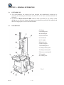
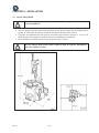
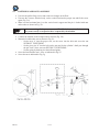
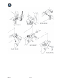
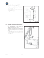
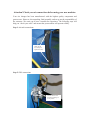
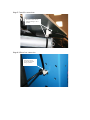
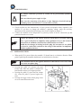
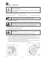
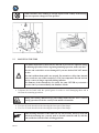
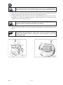
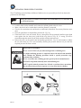
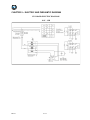
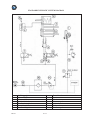
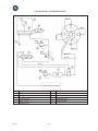
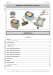
PRINTING CHARACTERS AND SYMBOLS
Throughout this manual, the following symbols and printing characters are used to facilitate reading:
Indicates the operations which need proper care
Indicates prohibition
Indicates a possibility of danger for the operators
BOLD TYPE Important information
WARNING: before operating the lift and carrying out any adjustment, read
carefully chapter 7 “installation” where all proper operations for a better
functioning of the lift are shown.
REV. 01
2 / 27
CONTENTS
1
INTRODUCTION
4
2
GENERAL INFORMATION
6
3
TRANSPORT, UNPACKING AND STORAGE
9
4
INSTALLATION
10
5
OPERATION
16
6
INFLATING
20
7
MAINTENANCE
22
8
TROUBLESHOOTING
24
9
ELECTRIC AND PNEUMATIC DIAGRAM
25
REV. 01
3 / 27
CHAPTER 1 – INTRODUCTION
1.1
INTRODUCTION
Thank you for purchasing a product from the line of tire changers. The machine has been
manufactured in accordance with the very best quality principles. Follow the simple instructions
provided in this manual to ensure the correct operation and long life of the machine. Read the entire
manual thoroughly and make sure you understand it.
1.2
TYRE CHANGER IDENTIFICATION DATA
A complete description of the “Tire Changer Model” and the “Serial number” will make it easier for
our technical assistance to provide service and will facilitate delivery of any required spare parts. For
clarity and convenience, we have inserted the data of your tire changer in the box below. If there is
any discrepancy between the data provided in this manual and that shown on the plate fixed to the tire
changer, the latter should be taken as correct.
LOGO
Type:
Volt
Amp
Kw
Ph
Hz
Year of manufacturing:
Air supply: 8-10 bar (115 – 145 PSI)
1.3
MANUAL KEEPING
For a proper use of this manual, the following is recommended:
x Keep the manual near the lift, in an easily accessible place.
x Keep the manual in an area protected from the damp.
x Use this manual properly without damaging it.
x Any use of the machine made by operators who are not familiar with the instructions and
procedures contained herein shall be forbidden.
This manual is an integral part of the manual: it shall be given to the new owner if and when the
machine is resold.
The illustrations have been made out of prototypes pictures. It is therefore
possible that some parts or components of standard production differ from those
represented in the pictures.
1.4
GENERAL SAFETY PRECAUTIONS
The tire changer may only be used by specially trained and authorized expert
personnel.
REV. 01
4 / 27
x
x
x
Any tampering or modification to the equipment carried out without the manufacturer’s prior
authorization will free him from all responsibility for damage caused directly or indirectly by
the above actions.
Removing or tampering with safety devices immediately invalidates the guarantee.
The tire changer comes complete with instruction and warning transfers which are designed
to be long-lasting. If they should for any reason be damaged or destroyed, please ask
immediately for replacements from the manufacturer.
TO THE READER
Every effort has been made to ensure that the information contained in this manual is correct, complete
and up-to date. The manufacturer is not liable for any mistakes made when drawing up this manual and
reserves the right to make any changes due the development of the product, at any time
REV. 01
5 / 27
CHAPTER 2 – GENERAL INFORMATION
2.1
INTENDED USE
x
x
2.2
This Semi-automatic tire changer has been designed and manufactured exclusively for
removing and mounting tires from/onto rims from 10" to 26" and a maximum diameter of
1000 mm.
In particular THE MANUFACTURER cannot be held responsible for any damage caused
through the use of this tire changer for purposes other than those specified in this manual, and
therefore inappropriate, incorrect and unreasonable.
DESCRIPTION
G) Clamps
I) Mounting head
M) Mounting bar
N) Horizontal arm
P) Vertical arm
Q) Air supply
R) Bead breaker
S) Wheel support
T) Bead lifting lever
U) Clamp control pedal
V) Clamp control pedal
Z) Reverser control pedal
Y) Turntable
K) Locking lever
Fig . 1
REV. 01
6 / 27
2.3
REV. 01
DANGER WARNING SIGNS
7 / 27
2.4
TECHNICAL SPECIFICATION
11 7/8" - 26"
External locking rim dimension
12 7/8" - 27"
13 3/4" - 28"
13 7/8" - 27 7/8
Internal locking rim dimension
14 5/8" - 28 7/8"
15 5/8" - 29 7/8"
Max. tire diameter
1200mm (47.5”)
Max tire width
470mm (18.5”)
Force on bead breaker blade (10 bar)
2500 kg
Working pressure
10 bar (145 psi)
Inflating pressure device max.
3.5 bar (50 psi)
Power supply voltage
110V 1Ph
Motor power
1.1 kw (1ph)
Max spindle torch
885 ft/lbs
Dimension
1140 x 1100 x 950
Net weight
240 kg STND
Noise level in working condition
REV. 01
< 70 dB (A)
8 / 27
ATTENTION!
The TC289 Tire Changer now has an improved turntable size. Please
read the information below.
Due to our continuous efforts to improve our products’ features and performance, the
published specifications of these products are sometimes updated to maintain accuracy.
Your TC289 Tire Changer has a new, larger sized turntable. The clamping ranges that are
listed on pages 8 and 15 in the TC289 Installation and Service Manual have been
changed to show this improvement. The new turntable clamping ranges are listed below:
External Clamping Range
Position 1) 11 7/8" - 26"
Position 2) 12 7/8" - 27"
Position 3) 13 3/4" - 28"
Internal Clamping Range
Position 1) 13 7/8" - 27 7/8"
Position 2) 14 5/8" - 28 7/8"
Position 3) 15 5/8" - 29 7/8"
External Locking Rim Dimension
(With Flip Adapters in the ATV Configuration)
Position 1) 4 7/8" - 19"
Position 2) 5 3/4" - 20"
Position 3) 6 3/4" - 20 7/8"
External Locking Rim Dimension
(With Flip Adapters in the Motorcycle Configuration)
Position 1) 15" - 29 1/8"
Position 2) 15 7/8" - 30"
Position 3) 16 7/8" - 31"
Note: The ranges listed above are actual measurements in inches. These do not indicate
specific wheel sizes. Most vehicle wheels are larger than their nominal size. For example,
a 16” wheel may be up to 17.5” in actual diameter.
Because of variances in wheel designs, a specific clamping range measurement does not
guarantee that a particular wheel size can always be clamped into place.
CHAPTER 3 – TRANSPORTATION, UNPACKING AND STORAGE
3.1
TRANSPORTATION
x
x
3.2
The tire changer must be transported in its original packaging and kept in the position shown
on the package itself.
The packaged machine may be moved by means of a fork lift truck of suitable capacity. Insert
the forks at the points shown in figure 3.
UNPACKING
x
x
Remove the protective cardboard and the nylon bag.
Check that the equipment is in perfect condition, making sure that no parts are damaged or
missing. Use fig. 1 for reference.
If in doubt do not use the machine and contact your retailer.
3.3
STORAGE
In the event of storage for long periods of time, be sure to disconnect all sources of power and grease
the clamp sliding guides on the turntable to prevent them from oxidizing.
REV. 01
9 / 27
CHAPTER 4 – INSTALLATION
4.1 SPACE REQUIRED
When choosing the place of installation be sure that it complies with current safety
at work regulations.
x
x
x
The tire changer must be connected to the main electric power supply and the compressed air
system. It is therefore advisable to install the machine near these power sources.
The place of installation must also provide at least the space shown in pictures 4 - 4/A so as to
allow all parts of the machine to operate correctly and without any restriction.
If the machine is installed outside it must be protected by a lean-to.
The tire changer with electric motor cannot be used in explosive atmospheres,
unless it is a proper version.
REV. 01
10 / 27
4.2
POSITIONING AND PARTS ASSEMBLY
x
x
x
Unscrew the pallet fixing screws and set the tire changer on the floor.
Unscrew the 4 screws from the body, set the vertical arm into the proper seat and fix the screw
again (Fig. 5/a).
Make sure the horizontal arm is on the vertical arm’s support and the pin is locked with nuts
and washers as shown in Fig. 5/b.
Before connecting all the power sources ALWAYS check your installations.
They must exactly correspond to those requested by the machine.
x
x
x
x
REV. 01
Connect the machine to the compressed air network (Fig. 5/d)
Mount the bead breaker arm as shown in Fig. 5/e:
- Set the arm “a” into the proper seat, set the screw into the hole and screw the nut
WITHOUT TIGHTENING.
- Set the pivot pin “b” into the hole on the arm and let the cylinder’s shaft pass through
the pin’s hole. Screw two nuts WITHOUT TIGHTENING.
- Set the spring by hooking it at the indicated points.
Screw the bead breaker arm’s screw as indicated in Fig 5/f
Screw the nut as indicated in Fig 5/g
11 / 27
REV. 01
12 / 27
4.2.2 Mounting and connecting the GT
x
x
Route the tube (1), situated inside the
machine body, though the hole on the back
side of the body.
Connect the hose (4) to the connectors (2)
using the bands (3).
4.2.3 Mounting and connecting the manometer
x
x
x
REV. 01
Fix the manometer to the vertical arm
through the proper screw. Fig. 11.
Route the connecting spiral hose through the
small hole on the back side of the machine
body.
Connect the rilsan hose to the union of the
pressure limiting device, situated on the
inflating pedal.
13 / 27
Attention! Check your air connections before using your new machine.
Your tire changer has been manufactured with the highest quality components and
greatest care. However, the unpacking, final assembly, and set up are the responsibility of
the customer. We want you to have a trouble-free experience. The following steps will
help you “check your work” and ensure that your machine will operate reliably.
Step 1: Air tank connections
Make sure the
hose clamps are
tightened securely
Step 2: FRL connections
Press the air lines into
the push-lock fittings as
far as possible.
Step 3: Turntable connections
Press the air lines into the
push-lock fittings as far as
possible.
Step 4: Inflator box connection
Press the air line as
far into the push-lock
fitting as possible.
Step 5: Accessory connections
Press all of the air lines into the
push-lock connectors as far as
possible.
4.3
COMMISSIONING
Any electric connection job must be carried out by professionally qualified
personnel.
Make sure that the power supply is right.
Make sure the connection of the phases is right. Improper electrical hook-up
can damage motor and will not be covered under warranty.
x
x
Check to make sure the characteristics of your systems correspond to those required by the
machine. If you have to change the machine’s operating voltage, make the necessary
adjustments to the terminal board referring to the electric diagram in chapter 9.
Connect the machine to the compressed air system by means of the air connection (Q) that
protrudes from the rear section.
Connect the machine to the electric network, which must be provided with line
fuses, a good earth plate in compliance with regulations in force and it must be
connected to an automatic circuit breaker (differential) set at 30 mA.
Should the tire-changer be lacking in electric plug, the user must set one, which
is at least 16 A and which conforms to the voltage of the machine, in compliance
with the regulations in force.
4.4
OPERATING TESTS
x
When pedal (Z) is pressed down the turntable (Y) should turn in a clockwise direction. When
pedal is pulled up the turntable should turn in an anticlockwise direction.
If the turntable turns in the opposite direction to that shown, reverse two of the
wires in the tree-phase plug.
x
x
x
REV. 01
Pressing the pedal (U) activates the bead
breaker (R); when the pedal is released the
bead breaker returns to its original position.
Pressing the pedal (V) opens the four clamps
(G); when the pedal is pressed again they
close.
Pressing the trigger on the airline gauge cause
air to be released from the head.
14 / 27
4.4.1
GT version
Do NOT LEAN on the turntable during this operation. Possibly dirty dust on
turntable could offend the operator’s eyes. For the same reason, be carefully as
not to accidentally push the inflating pedal while working.
x
x
4.5
When the pedal located on the left side of the machine
body is pushed down to its intermediate position (B),
air is released from the airline gauge.
When the pedal (C) is pushed down completely, air is
released from the airline gauge with a powerful jet from
the nozzles located on the turntable clamps.
TURNTABLE LOCKING VALUE ADJUSTING
Fig. 13
The tire changer turntable is preset by the manufacturer on a middle range measure from11” to 23”
ext. (considering the rim outer side and) from 13” – 25” int. (if you lock the rim from inner side).
It is however possible to change this dimension range in case of need when working on larger or
small rims; it is enough to change the position of the 4 clamps are shown in the figures below.
The obtainable value starts from a minimum of 10”-22” ext. and 12”-24” int. until a maximum of 12”24” ext. and 14”-26” int.
To change the position, proceed as follows:
x Unscrew screw (1) by means of the Allen wrench.
x Remove the locking clamp (2) and the slide piece (3).
x Align the slide hole with one of the guide holes (4) according to the locking dimensions you
want to set. Use the measures below for reference.
It is important to perform the above mentioned operation for all the 4 clamps to
avoid any unbalance in locking phase.
REV. 01
15 / 27
CHAPTER 5 – OPERATION
Do not use the machine until you have read and understood the entire manual
and the warning provided.
Before carrying out any operation, deflate the tire and take off all the wheel
balancing weights.
The operation of the tire changer is divided into three parts:
a) BREAKING THE BEAD
b) REMOVING THE TIRE
c) MOUNTING THE TIRE
It is advised to equip the tire changer with the pressure regulator.
5.1
BREAKING THE BEAD
Bead breaking must be done with the utmost care and attention. When the bead
breaker pedal is operated the bead breaker arm moves quickly and powerfully.
Anything within its arrange of action can be in danger of being crushed.
x
x
Check that the tire is deflated. If not, deflate it.
Close the turntable clamps completely.
Bead breaking with the clamps in open position can be extremely dangerous for
operator’s hands.
During bead breaking operations NEVER touch the side of the tire.
x
x
x
x
REV. 01
Position the wheel against the rubber stops on the right side of the tire changer (S).
Position the bead breaker (R) against the tire bead at a distance of about 1 cm from the rim (fig.
8). Pay attention to the blade, which must operate correctly onto the tire and not onto the rim.
Press down the pedal (U) to activate the bead breaker and release it when the blade has reached
the end of its travel or in any case when the bead is broken.
Rotate the tire slightly and repeat the operation around the entire circumference if the rim and
from both sides until the bead is completely detached from the rim.
16 / 27
5.2
REMOVING THE TIRE
Before any operation make sure to remove the old wheel balancing weights and
check that the tire is deflated.
During arm tilting make sure that nobody stats behind the tire changer.
x
Spread the supplied grease (or grease of a similar type) onto the tire bead.
Failure to use the grease could cause serious damage to the tire bead.
During rim locking MEVER keep your hands under the tire. For a correct
locking operation set the tire exactly in the middle of turntable.
OUTER LOCKING
INNER LOCKING
x
x
Position the clamps (G) according to the
reference mark on the turntable (Y) by
pressing pedal (V) down to its
intermediate position.
Place the tire on the clamps and keeping
the rim pressed down, press the pedal (V)
as far as it will go.
x
x
Position the clamps (G) so that they are
completely closed.
Place the tire on the clamps and press the
pedal (V) to open the clamps and thereby
lock the rim.
Make sure that the rim is firmly fixed to the clamps.
Never keep your hands onto the wheel: the arm recovery to “working position”
could set the operator at risk of hand crushing between rim and mounting head.
x
x
Lower the mounting bar (M) so that the mounting head (I) rests against the edge of the rim and
lock it using the lever (K). This will lock the arm in both vertical and horizontal direction and
move the mounting head (I) of about 2 mm from the rim.
With the lever (T) inserted between the bead and the front section of the mounting head (I),
move the tire bead over the mounting head.
In order to avoid damaging the inner tube if there is one, it is advisable to carry
out this operation with the valve about 10 cm right of the mounting head. (Fig.
16)
x
x
REV. 01
With the lever held in this position, rotate the turntable (Y) in a clockwise direction by pressing
pedal (Z) down until the tire is completely separated from the wheel rim.
Remove the inner tube if there is one and repeat the operation for the other bead.
17 / 27
Chains, bracelets, loose clothing or foreign objects in the vicinity of the moving
parts can represent a danger for the operator.
5.3
MOUNTING THE TIRE
It is utmost important to check the tire and rim to prevent tire explosion during
the inflating operations. Before beginning mounting operation, make sure that:
The tire and cord fabric are not damaged. If you note defects DO NOT mount
the tire.
The rim is without dents and is not warped. Pay attention to alloy rims, internal
micro-cracks are not visible to naked eye. This can compromise the rim and can
also be a source of danger especially during inflation.
The diameter of the rim and tire are exactly the same. NEVER try to mount a
tire on a rim if you cannot identify the diameter of both.
x
Lubricate the tire beads with the special grease in order to avoid damaging them and to
facilitate the mounting operations.
During rim locking MEVER keep your hands under the tire. For a correct
locking operation set the tire exactly in the middle of turntable.
x
x
For 10 to 20 inch wheels lock the rim using the inner part of the clamps.
For 12 to 22 inch wheels lock the rim using the outer part of the clamps.
When working with rims of the same size it is not necessary always to lock and
unlock the mounting bar; you only need to tilt and return the ram (P) with the
arm and the bar locked in their working positions.
REV. 01
18 / 27
Never keep your hands onto the wheel: the arm recovery to “working position”
could set the operator at risk of hand crushing between rim and mounting head.
x
x
Move the tire so that the bead passes below the front section of the mounting head and is
brought up against the edge of the rear section of the mounting head itself.
Keeping the tire bead pressed down into the wheel rim channel with your hands, press down on
the pedal (Z) to rotate the turntable clockwise. Continue until you have covered the entire
circumference of the wheel rim (Fig. 12).
To prevent industrial accidents, keep hands and other parts of the body as far as
possible from the tool arm when the table top is turning.
x
Insert the inner tube if there is one and repeat the same operations to mount the upper side of
the tire.
Demounting and mounting are always done with the clockwise turntable
rotation. Anticlockwise rotation is used only to correct operator’s errors or if
the turntable stalls.
REV. 01
19 / 27
CHAPTER 6 – INFLATING
The greatest attention is called for when inflating the tires. Keep strictly to the
following instructions since the tire changer is NOT designed and built to
protect (or anyone else in the vicinity of the machine) if the tire bursts
accidentally.
A bust tire can cause serious injury or even death of the operator.
Check carefully that the wheel rim and the tire are of the same size.
Check the state of wear of the tire and that it has no defects before
beginning the inflation.
Inflate the tire with brief jets of air, checking the pressure after every jet.
All our tire changers are automatically limited to a maximum inflating
pressure of 3.5 bar (51 psi). In any case NEVER EXCEEED THE
PRESSURE RECOMMENDED BY THE MANUFACTURER.
Keep your hands and body as far away as possible from the tire.
To inflate a tire proceed as follows:
x
x
x
x
x
Connect the airline gauge to the tire valve.
Make a last check to be certain that tire and rim
diameter correspond.
Check to be certain that rim and beads are
sufficiently lubricated. If necessary lubricate some
more.
Seat the beads with short jets of air. Between air
jets, check the air pressure on the inflator gauge.
Continue to inflate the tire with short jets of air
and constantly checking the pressure between
until the required pressure has been reached.
EXPLOSION HAZARD!
Never exceed 3.5 bar (51 psi) when seating beads or inflating tires.
If a higher inflating pressure is required remove the wheel from turntable
and continue the inflating procedure inside a special protection cage
(commercially available).
Never exceed the max. inflating pressure given by the tire manufacturer.
ALWAYS keep hands and body back from inflating tire.
ONLY special trained personnel are allowed to perform these operations.
Do not allow other persons to operate or to stay near the tire changer.
REV. 01
20 / 27
6.1
INFLATING TIRES WITH GT SYSTEM
The GT inflating system facilitates inflation of tubeless tires to a powerful jet of air from the nozzle
positioned on the clamps.
During this phase of work he level of noise can reach 85db (A). It is advisable to
use a noise protection.
x
x
x
x
x
x
Lock the wheel on the turntable and connect the inflating head to the tire valve.
Make a last check to be certain that tire and rim diameter correspond.
Check to be certain that rim and beads are sufficiently lubricated. If necessary lubricate some
more.
Press the pedal down to intermediate position (B – Fig. 21)
If the bead of tire is not well seated, due to a strong bead, lift tire manually until the upper bead
seats against the rim, then press pedal all the way down (C-Fig. 21). A strong jet will be
released through the nozzles in the slides and this will help the bead seal.
Release the tires; set the pedal in the intermediate position (B – Fig. 21) and continue to inflate
the tire with short jets of air and constantly checking the pressure between air jets until the
required pressure has been reached.
EXPLOSION HAZARD!
Never exceed 3.5 bar (51 psi) when seating beads or inflating tires.
If a higher inflating pressure is required remove the wheel from turntable
and continue the inflating procedure inside a special protection cage
(commercially available).
Never exceed the max. inflating pressure given by the tire manufacturer.
ALWAYS keep hands and body back from inflating tire.
ONLY special trained personnel are allowed to perform these operations.
Do not allow other persons to operate or to stay near the tire changer.
REV. 01
21 / 27
CHAPTER 7 – MAINTENANCE
7.1
GENERAL WARNINGS
Unauthorized personnel may not carry out maintenance work.
x
Regular maintenance as described in the manual is essential for correct operation and long
lifetime of the tire changer.
If maintenance is not carried out regularly, the operation and reliability of the machine may be
compromised, thus placing the operator and anyone else in the vicinity at risk.
x
Before carrying out any maintenance work, disconnect the electric and
pneumatic supplies. Moreover, it is necessary to break the bead without load 3-4
times in order to let the air in pressure go out of the circuit.
x
Defective parts must be replaced exclusively by expert personnel using the manufacturer’s
parts.
Removing or tampering with safety devices (pressure limiting and regulating valves) is
extremely forbidden.
x
In particular the Manufacturer shall not be held responsible for complaints
deriving from the use of spare parts made by other manufacturers or for
damage caused by tampering or removal of safety systems.
7.2
MAINTENANCE OPERATIONS
¾ Clean the turntable once a week with diesel fuel so as to prevent the formation of dirt, and
grease the clamp sliding guides.
¾ Carry out the following operations at least every 30 days:
x Check the oil level in the lubricator tank. If necessary, fill up by unscrewing the reservoir F.
Only use ISO VG viscosity ISOHG class oil for compressed air circuit. (Fig. 14)
x Check that a drop of oil is injected into the reservoir F very 3-4 times the pedal U is pressed
down. If not, regulate using the screw D (fig. 14)
¾ After the first 20 days of work, retighten the clamp tightening screws on the turntable slides
(Fig. 15).
¾ In the event of a loss of power, check that the drive belt is tight as follows.
Before any operation disconnect the electric power supplies.
x Remove the left side body panel of the tire changer by unscrewing the four fixing screws.
x Remove the drive belt by means of the special adjusting screw X on the motor support (Fig.
16).
REV. 01
22 / 27
¾ If necessary to adjust the vertical arm locking plate because the tool does not lock or it does not
rise from the rim of 2mm necessary for working, adjust nuts as shown in Fig. 17.
For cleaning or replacing the silencer for opening/closing clamps, see Fig 18 and proceed as follows:
1. Remove the left side panel of the machine body by unscrewing the four fixing screws.
2. Unscrewing the silencer put on the pedal system, on the clamp opening/closing pedal.
3. Clean by a jet of compressed air or, if damaged, replace by referring to the spare parts
catalogue.
For cleaning or replacing the silencer of bead breaker, see Fig. 19 and proceed as shown on previous
point 1 and 3.
REV. 01
23 / 27
CHAPTER 8 – TROUBLE-SHOOTING
TROUBLE:
POSSIBLE CAUSE:
Turntable rotates only in
Reverser broken
one direction.
Belt broken
Replace reverser
Replace
Reverser broken
Turntable does not rotate.
Problem with motor
Turntable locks
SOLUTION:
Belt loose
Replace reverser
Check for loose wire in the
motor, plug or socket.
Replace motor
Adjust the belt tension (chap. 7
Fig. 24)
Clamp slow to open or
Silencer clogged
Clean or replace silencer
close
Replace clamps
Turntable does not lock Clamps worn
the wheel rim correctly
Turntable cylinder(s) defective
Replace cylinder gasket
The tool touches the rim Locking plate incorrectly adjusted or Adjust or replace locking plate
(chap 7 – Fig 25)
during the tire removing defective
or mounting operations
Turntable locking screw loose
Tighten screw
Pedal lock out of
Return spring broken
Replace spring
working position
Clean or replace silencer (chap 7
Bead breaking operation Silencer clogged
– Fig. 27)
difficult
Bead breaker cylinder gasket broken
Replace gasket
REV. 01
24 / 27
CHAPTER 9 – ELECTRIC AND PNEUAMTIC DIAGRAM
STANDARD ELECTRIC DIAGRAM
110V - 1PH
REV. 01
25 / 27
STANDARD PNEUMATIC SYSTEM DIAGRAM
1
2
3
4
5
6
7
REV. 01
Inflating gauge
Silencer 1/4”
Silencer 1/8”
Quick relief valve
Bead breaker cylinder
Turntable cylinder
Bead breaking valve
8
9
10
11
12
13
14
26 / 27
Turntable valve
Rotation union
Lubricator
Pressure regulator
Air intake cock
Safety valve
Pressure regulator
GT PNEUMATIC SYSTEM DIAGRAM
3
4
5
6
8
9
REV. 01
Safety Valve
Tank
Setting solenoid valve
GT pedal valve
Safety Valve
Inflating head
10
11
12
13
14
27 / 27
Divider
Pressure gauge
Inflating unit
Deflating valve
Rotation union
Warranty
This item has a one (1) year LIMITED warranty.
Atlas® Automotive Equipment warrants the equipment to the
original purchaser against defects in material or workmanship
under normal use for a period of one year from the date of
purchase. This warranty shall be limited to the replacement of
materials or parts found defective, at the discretion of Atlas®
Automotive Equipment and/or its authorized distributors. This limited one (1) year warranty
DOES NOT apply to normal wear items (turntable jaws, belts, gauges, plastic jaw protectors,
etc.). The limited one (1) year warranty does not include a labor warranty. Warranties do not
apply to items that have been abused or misused.
Returned goods must be authorized to be returned (in writing) by Atlas® Automotive Equipment
and/or an authorized distributor and must be prepaid to a designated location. All returns may
be subject to a 15% handling and restocking charge. Returned goods must be in like-new
condition complete with warranty and original shipping papers.
Customer’s Responsibilities
•
•
•
•
•
Shall ensure that all air operated components are properly maintained
Shall ensure components are powered by well lubricated and moisture free compressed air
(if a suspected defective part has not been properly lubricated it will not be covered under
warranty)
Shall establish procedures to periodically maintain and inspect the equipment
Shall ensure that your wheel balancer is protected by a surge protector
Shall ensure that all equipment shall have adequate amperage service
THIS WARRANTY IS EXCLUSIVE AND IS LIEU OF ALL OTHER WARRANTIES EXPRESSED OR
IMPLIED INCLUDING ANY IMPLIED WARRANTY OR MERCHANTABILITY OR ANY IMPLIED
WARRANTY OF FITNESS FROM A PARTICULAR PURPOSE, AND ALL SUCH IMPLIED WARRANTIES
ARE EXPRESSLY EXCLUDED.
THE REMEDIES DESCRIBED ARE EXCLUSIVE AND IN NO EVENT SHALL THE MANUFACTURER,
NOR ANY SALES AGENT OR OTHER COMPANY AFFILIATED WITH IT OR THEM, BE LIABLE
FOR SPECIAL CONSEQUENTIAL OR INCIDENTAL DAMAGES FOR THE BREACH OF OR DELAY
IN PERFORMANCE OF THIS WARRANTY. THIS INCLUDES, BUT IS NOT LIMITED TO, LOSS OF
PROFIT, RENTAL OR SUBSTITUTE EQUIPMENT OR OTHER COMMERCIAL LOSS.
For warranty assistance, please call 866-898-2604. Please have your invoice number ready so
that we may be able to serve you better. Warranty procedures cannot be initiated without an
invoice number corresponding to the product serial number.
For further product and distributor information, please visit www.atlasautoequipment.com