1
EQUO Sensor Series
Air Thermo Logger
ZN-THX11-S□
User’s Manual
Rev.C
Introduction
Thank you for purchasing EQUO Sensor Series Air Thermo Logger ZN-THX11-S□.
This manual describes the information regarding the functions, performance and usage that are necessary to
use the Air Thermo Logger.
・ This product must be handled by specialists with electrical knowledge.
・ Before using this product, read this sheet thoroughly to acquire sufficient knowledge of the product.
・ For your convenience, keep this instruction sheet at hand to refer whenever necessary.
Trademarks
・Microsoft and Windows are registered trademarks or trademarks of Microsoft Corporation in the United
States and other countries.
・Other company names and product names are registered trademarks or trademarks of the respective
company.
Manual type and usage
The major contents of the manuals are shown below. Select and read a manual according to your need.
Included manual (Print)
Instruction Sheet
Describes the information to ensure the safe and proper use of the product, and information
regarding ratings, performance and installation.
Startup Guide
Describes the basic procedures including content check, assembly, setting operation, recording
operation and data display.
Manual included in the Utility Disk (PDF data)
User's Manual (This document)
Information to ensure the safe and proper use of the product
Detailed procedures including content check, assembly, setting operation, recording operation and
data display
Describes the necessary information such as specifications of the unit to use the Air Thermo
Logger ZN-THX11-S□.
i
Read and Understand this Manual
Please read and understand this manual before using the products. Please consult your
OMRON representative if you have any questions or comments.
Warranty and Limitations of Liability
<WARRANTY>
OMRON's exclusive warranty is that the products are free from defects in materials and
workmanship for a period of one year (or other period if specified) from date of sale by
OMRON.
OMRON MAKES NO WARRANTY OR REPRESENTATION, EXPRESS OR IMPLIED,
REGARDING NON-INFRINGEMENT, MERCHANTABILITY, OR FITNESS FOR PARTICULAR
PURPOSE OF THE PRODUCTS. ANY BUYER OR USER ACKNOWLEDGES THAT THE
BUYER OR USER ALONE HAS DETERMINED THAT THE PRODUCTS WILL SUITABLY
MEET THE REQUIREMENTS OF THEIR INTENDED USE. OMRON DISCLAIMS ALL
OTHER WARRANTIES, EXPRESS OR IMPLIED.
<LIMITATIONS OF LIABILITY>
OMRON SHALL NOT BE RESPONSIBLE FOR SPECIAL, INDIRECT, OR CONSEQUENTIAL
DAMAGES, LOSS OF PROFITS OR COMMERCIAL LOSS IN ANY WAY CONNECTED WITH
THE PRODUCTS, WHETHER SUCH CLAIM IS BASED ON CONTRACT, WARRANTY,
NEGLIGENCE, OR STRICT LIABILITY.
In no event shall the responsibility of OMRON for any act exceed the individual price of the
product on which liability is asserted.
IN NO EVENT SHALL OMRON BE RESPONSIBLE FOR WARRANTY, REPAIR, OR OTHER
CLAIMS REGARDING THE PRODUCTS UNLESS OMRON'S ANALYSIS CONFIRMS THAT
THE PRODUCTS WERE PROPERLY HANDLED, STORED, INSTALLED, AND MAINTAINED
AND NOT SUBJECT TO CONTAMINATION, ABUSE, MISUSE, OR INAPPROPRIATE
MODIFICATION OR REPAIR.
ii
Application Considerations
<SUITABILITY FOR USE>
OMRON shall not be responsible for conformity with any standards, codes, or regulations that
apply to the combination of the products in the customer's application or use of the products.
At the customer's request, OMRON will provide applicable third party certification documents
identifying ratings and limitations of use that apply to the products. This information by itself
is not sufficient for a complete determination of the suitability of the products in combination
with the end product, machine, system, or other application or use.
The following are some examples of applications for which particular attention must be given.
This is not intended to be an exhaustive list of all possible uses of the products, nor is it
intended to imply that the uses listed may be suitable for the products:
Outdoor use, uses involving potential chemical contamination or electrical interference, or
conditions or uses not described in this manual.
Nuclear energy control systems, combustion systems, railroad systems, aviation systems,
medical equipment, amusement machines, vehicles, safety equipment, and installations
subject to separate industry or government regulations.
Systems, machines, and equipment that could present a risk to life or property.
Please know and observe all prohibitions of use applicable to the products.
NEVER USE THE PRODUCTS FOR AN APPLICATION INVOLVING SERIOUS RISK TO LIFE
OR PROPERTY WITHOUT ENSURING THAT THE SYSTEM AS A WHOLE HAS BEEN
DESIGNED TO ADDRESS THE RISKS, AND THAT THE OMRON PRODUCTS ARE
PROPERLY RATED AND INSTALLED FOR THE INTENDED USE WITHIN THE OVERALL
EQUIPMENT OR SYSTEM.
<PROGRAMMABLE PRODUCTS>
OMRON shall not be responsible for the user's programming of a programmable product, or
any consequence thereof.
Disclaimers
<CHANGE IN SPECIFICATIONS>
Product specifications and accessories may be changed at any time based on improvements
and other reasons.
It is our practice to change model numbers when published ratings or features are changed, or
when significant construction changes are made. However, some specifications of the
products may be changed without any notice. When in doubt, special model numbers may
be assigned to fix or establish key specifications for your application on your request. Please
consult with your OMRON representative at any time to confirm actual specifications of
purchased products.
<DIMENSIONS AND WEIGHTS>
Dimensions and weights are nominal and are not to be used for manufacturing purposes, even
when tolerances are shown.
<ERRORS AND OMISSIONS>
The information in this manual has been carefully checked and is believed to be accurate;
however, no responsibility is assumed for clerical, typographical, or proofreading errors, or
omissions.
<COPYRIGHT AND COPY PERMISSION>
This manual shall not be copied for sales or promotions without permission.
This manual is protected by copyright and is intended solely for use in conjunction with the
product. Please notify us before copying or reproducing this manual in any manner, for any
other purpose. If copying or transmitting this document to another, please copy or transmit it in
its entirety.
iii
Precautions on Safety
Meanings of Signal Words
For the safe operation of ZN-THX21-S□, this operation manual indicates the precautions by using the marks
and symbols as indicated below. The precautions given here contains important information related to safety.
Be sure to observe them. The marks and symbols for the safety precautions are as follows:
WARNING
Indicates a potentially hazardous situation which, if not avoided,
will result in minor or moderate injury, or may result in serious
injury or death. Additionally there may be significant property
damage.
CAUTION
Indicates a potentially hazardous situation which, if not avoided,
may result in minor or moderate injury or in property damage.
●Meanings of Alert Symbols
●Disassembly Prohibition
Indicates that disassembly is prohibited to prevent electric shock.
●Explosion Caution
Indicates the possibility of explosion under specific conditions.
●Warning Indications
WARNING
As this product contains a lithium battery, fire, explosion or burning hazards may
occur. Dispose of the product as industrial waste. Do not disassemble, deform,
heat, or burn this product.
Do not disassemble or touch inside the unit. Doing so may result in electric
shock and/or injury.
iv
PRECAUTIONS FOR SAFE USE
Observe the following precautions to ensure safe operation.
Do not install the product in the places subject to exposure to water, oil, or chemicals.
When using an AC adapter, use only the provided AC adapter.
When using a DC cable, use only the provided DC cable.
If a voltage that exceeds the rated voltage is applied to the AC adapter or DC cable, smoking may occur.
Do not connect a power supply that exceeds the rated voltage. In a situation where a voltage higher than
the rating is applied, use protective equipment so that the power supply voltage does not exceed the
rated voltage.
Dispose of the product as industrial waste.
To use the batteries properly, read the precautions written by manufacturer before use.
Do not subject the product to a shock such as dropping the product. Doing so may cause damage to or
malfunction of the product. It is recommended to secure screws when mounted on the wall surface to
prevent damage from dropping the product. If strong impact is applied to the product, stop use of the
product.
When inserting or pulling out the SD card, hold the main unit to prevent damage from dropping the
product. When inserting or pulling out an AC adapter or DC cable, alarm output cable or sensor
connector, hold the unit as well.
Mount an appropriate load on the alarm output terminals due to the possibility of smoking.
If liquid crystal leaks due to a damage to the LCD panel, be careful so that your skin will not touch with or
you will not inhale or swallow it. If liquid crystal enters into your mouth, seek medical attention.
v
Precautions for Correct Use
1. Avoid installing the product in the following places:
Places exceeding the rated ambient temperature
Places exposed to extreme temperature changes (prevent condensation.)
Places exceeding the rated RH level
Places subject to corrosive or flammable gases
Places subject to mist, droplets, coarse particles, fiber, salt, metal dust, or large amount of particles
Places subject to direct shock or vibration
Places subject to direct sunlight
Places subject to exposure to water, oil, or chemicals
Places subject to strong magnetic field or electric field
Outdoors
2. Wiring
Lay the product cable away from any high-voltage cable or power line.
If laid in the same conduit or duct, induction noise from them may caused malfunction or breakdown of
the product.
Be sure to turn the power OFF before inserting or removing the I/O terminals. Otherwise it may result in
a failure.
Do not connect the product to a sensor head other than ZN-THS1□□-S. Do not hold only the sensor
head mounted to the product body.
3. Battery Use
Do not combine use of new and old batteries, or do not use batteries in combinations with those of
different makers or models. Doing so may result in malfunction.
Do not insert a battery with the polarity inverted.
Be sure to mount a battery cover during use. Be careful that the operation of the device cannot be
guaranteed if a battery is removed because the battery cover is not mounted.
Remove the batteries if you do not use the product for a long period of time. If leaving the used batteries
in the product for a long period of time, corrosion of the device may occur due to a battery leak.
Do not disassemble or throw the battery into the fire.
When the battery level is low, a restart may be repeated. If such event occurs, replace the batteries with
new ones.
4. Battery Disposal
For disposal of batteries after replacement, restrictions may apply depending on the local government.
Dispose of the battery according to your local government.
5. Seal at the bottom of the main unit
Never remove the seal at the bottom of the unit as there is a connector used for maintenance purpose
conducted by OMRON.
6. Mounting screw holes
The screw hole is M3 and the depth of the screw is 4 mm. Do not tighten a screw with more than 4 mm
in depth. Doing so may damage the product.
vi
Software License Agreement
This is a binding agreement between OMRON Corporation ("OMRON") and you (the "User") on the terms
and conditions of the license of the Software.
1 In this Agreement, "Software" means the computer program and related documentation contained
in this package. The "Software" shall include any derivative works thereto. Copyright of the Software
remains the sole property of OMRON or the third party who has licensed the Software to OMRON and
shall not be assigned to the User under this Agreement.
2 OMRON grants the User a non-exclusive, non-transferable and limited license to use the Software on one
computer owned by the User.
3 The User shall not sub-license, assign nor lease the Software to any third party without prior written
consent of OMRON.
4 The User may copy the Software for back-up purpose only. The User may not de-compile, reverse
engineer nor otherwise attempt to discern the source code of the Software.
5 The User may modify the Software and the modified Software shall be subject to the terms and conditions
of this Agreement, provided however that, OMRON shall not assume any liability for any modified
Software.
6 The User shall treat any information contained in the Software as confidential and shall not disclose it to
any third party. This obligation shall survive the termination of this Agreement.
7 OMRON warrants to the User that, for a period of one (1) year, the Software will perform substantially in
accordance with the user manual provided. If the User discovers defect of the Software (substantial
non-conformity with the manual), and return it to OMRON within the said one (1) year period, OMRON will
replace the Software without charge. The User acknowledges that all errors or bugs of the Software may
not be removed by such replacement.
8 THE ABOVE REPLACEMENT SHALL CONSTITUTE THE USER'S SOLE ANDEXCLUSIVE REMEDIES
AGAINST OMRON AND THERE ARE NO OTHER WARRANTIES, EXPRESSED OR IMPLIED,
INCLUDING BUT NOT LIMITED TO, WARRANTY OF MERCHANTABILITY OR FITNESS FOR
PARTICULAR PURPOSE. INNO EVENT, OMRON WILL BE LIABLE FOR ANY LOST PROFITS OR
OTHERINDIRECT, INCIDENTAL, SPECIAL OR CONSEQUENTIAL DAMAGES ARISING OUTOF THIS
AGREEMENT OR USE OF THE SOFTWARE.
9 In any event, OMRON's entire liability to the User for any cause shall not exceed the amount actually paid
by the User to purchase the Software.
(C)Copyright OMRON Corporation 2011
All Rights Reserved.
vii
How to Read This Manual
■ Meanings of Symbols
Menu items that are displayed on the screen, and windows, dialog boxes and other GUI elements displayed
on the PC are indicated enclosed by brackets "[ ]".
■ Explanation of Symbols
Important: Indicates the description of an essential point regarding a function, such as an important point
regarding operation or advice on how to use it.
Note: Indicates application procedures.
viii
Table of Contents
Introduction ........................................................................................................................................................i
Table of Contents.............................................................................................................................................ix
1.
Product Overview .................................................................................................................................. 1-1
1.1
2.
(1)
High-precision Air Thermo Sensor ............................................................................................ 1-1
(2)
Recording with SD card ............................................................................................................ 1-1
(3)
Graphical display software provided as standard ..................................................................... 1-1
(4)
Alarm output.............................................................................................................................. 1-1
(5)
Battery drive .............................................................................................................................. 1-1
Check and Preparation ......................................................................................................................... 2-1
2.1
Checking the Contents ..................................................................................................................... 2-1
2.2
Preparing Necessary Items .............................................................................................................. 2-1
2.3
Exterior Features .............................................................................................................................. 2-2
2.4
Input/Output Specifications .............................................................................................................. 2-3
2.4.1
Alarm output.............................................................................................................................. 2-3
(1)
Alarm output terminals .............................................................................................................. 2-3
(2)
Output specifications ................................................................................................................ 2-3
2.5
Assembly.......................................................................................................................................... 2-4
2.5.1
Connecting Air Thermo Sensor ................................................................................................. 2-4
2.5.2
Connecting alarm output terminals ........................................................................................... 2-4
2.5.3
Preparing power supply ............................................................................................................ 2-5
(1)
When supplying power from the outside................................................................................... 2-5
(2)
Using batteries .......................................................................................................................... 2-6
2.6
3.
Features and Functions ................................................................................................................... 1-1
Installing Air Thermo Logger ............................................................................................................ 2-7
2.6.1
Standing installation .................................................................................................................. 2-7
2.6.2
Securing with mounting screws ................................................................................................ 2-7
2.6.3
Mounting with screw hook hole................................................................................................. 2-7
2.7
Preparing Software SD Viewer ES................................................................................................... 2-9
2.8
Inserting/removing SD card ............................................................................................................. 2-9
2.8.1
Inserting SD card ...................................................................................................................... 2-9
2.8.2
Removing SD card .................................................................................................................... 2-9
Functions of the Operation Unit and Display ..................................................................................... 3-1
ix
3.1
3.1.1
Control key ................................................................................................................................ 3-1
3.1.2
Reset switch.............................................................................................................................. 3-1
3.2
4.
Control Unit ...................................................................................................................................... 3-1
Display Unit ...................................................................................................................................... 3-2
Setting Air Thermo Logger ................................................................................................................... 4-1
4.1
Setting Procedure and Operation Modes ........................................................................................ 4-1
4.2
Settings in FUN Mode ...................................................................................................................... 4-2
4.2.1
List of setting items ................................................................................................................... 4-2
4.2.2
Selecting operation mode “FUN” .............................................................................................. 4-3
4.2.3
Selecting items.......................................................................................................................... 4-4
4.2.4
Description of items .................................................................................................................. 4-5
(1)
Measured update cycle (CYCLE) ............................................................................................. 4-5
(2)
Processing mode (MEAS) ........................................................................................................ 4-5
(3)
Measurement operation mode (MODE) ................................................................................... 4-6
(4)
Recording mode (REC) ............................................................................................................ 4-7
(5)
Initialization (INIT) ..................................................................................................................... 4-7
(6)
Others (ETC)............................................................................................................................. 4-8
(7)
Reading setting data (RESTR) ................................................................................................. 4-8
(8)
Writing the setting data (BCKUP) ............................................................................................. 4-9
(9)
Setting time (TIME) ................................................................................................................... 4-9
(10)
YEAR, MONTH, DAY, CLOCK ................................................................................................ 4-10
(11)
Display mode at sleep (SDISP) .............................................................................................. 4-10
4.2.5
Changing the setting value ......................................................................................................4-11
(1)
Changing the setting value of the selection type (Example: Changing CYCLE) .....................4-11
(2)
Changing the setting value of the numeric value input type (Example: Changing YEAR) ..... 4-12
4.3
Making Settings (Operation in THR Mode) .................................................................................... 4-13
4.3.1
List of setting items ................................................................................................................. 4-13
4.3.2
Selecting operation mode ....................................................................................................... 4-14
4.3.3
Selecting items........................................................................................................................ 4-14
4.3.4
Description of items ................................................................................................................ 4-14
(1)
Upper limit of the temperature threshold value (DEGHI) ........................................................ 4-14
(2)
Lower limit of the temperature threshold value (DEGLO) ...................................................... 4-15
(3)
Upper limit of the humidity threshold value (RH HI) ............................................................... 4-15
(4)
Lower limit of the humidity threshold value (RH LO) .............................................................. 4-15
(5)
Setting alarm hold ................................................................................................................... 4-16
4.3.5
Changing the setting value ..................................................................................................... 4-16
4.4
Making Settings (Operation in SCL Mode) .................................................................................... 4-17
4.4.1
List of setting items ................................................................................................................. 4-17
x
4.4.2
Selecting operation mode ....................................................................................................... 4-17
4.4.3
Selecting items........................................................................................................................ 4-18
4.4.4
Description of items ................................................................................................................ 4-18
(1)
Adjusting temperature ............................................................................................................. 4-18
(2)
Adjusting humidity ................................................................................................................... 4-18
4.4.5
Changing the setting value ..................................................................................................... 4-19
4.5
5.
6.
Copying the Settings When Using Multiple Air Thermo Stations ................................................... 4-19
Measurement and Recording ............................................................................................................... 5-1
5.1
Selecting Operation Mode ............................................................................................................... 5-1
5.2
Screen Transition in RUN Mode ...................................................................................................... 5-2
5.3
Starting/Stopping Recording ............................................................................................................ 5-3
5.3.1
Starting recording ...................................................................................................................... 5-3
5.3.2
Stopping Recording .................................................................................................................. 5-3
5.4
Outputting the File to the SD card .................................................................................................... 5-4
5.5
Releasing the Held Alarm ................................................................................................................ 5-4
5.6
Hiding the Display ............................................................................................................................ 5-4
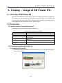
Display – Usage of SD Viewer ES - ...................................................................................................... 6-1
6.1
Overview of SD Viewer ES .............................................................................................................. 6-1
6.2
Preparation ....................................................................................................................................... 6-1
6.2.1
System requirements of SD Viewer ES .................................................................................... 6-1
6.2.2
Installing/uninstalling SD Viewer ES ......................................................................................... 6-1
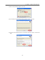
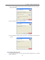
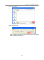
(1)
Installing SD Viewer ES ............................................................................................................ 6-1
(2)
Uninstalling SD Viewer ES........................................................................................................ 6-3
6.2.3
Preparing the recording data .................................................................................................... 6-4
6.3
Starting and Stopping SD Viewer ES ............................................................................................... 6-4
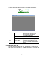
6.3.1
Starting SD Viewer ES .............................................................................................................. 6-4
6.3.2
Stopping SD Viewer ES ............................................................................................................ 6-5
6.4
Opening and Saving Data ................................................................................................................ 6-6
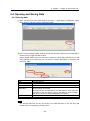
6.4.1
Opening data ............................................................................................................................ 6-6
(1)
”Display connected data” and “Display side-by-side” ............................................................. 6-10
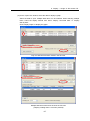
(2)
Resampling cycles ...................................................................................................................6-11
6.4.2
Saving data ............................................................................................................................. 6-13
6.5
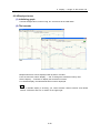
Displaying Graph ............................................................................................................................ 6-15
6.5.1
Names and functions in the graph window ............................................................................. 6-15
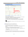
6.5.2
Basic graph operation ............................................................................................................. 6-17
xi
7.
(1)
Selecting the waveform .......................................................................................................... 6-17
(2)
Moving the waveform .............................................................................................................. 6-17
(3)
Moving the scale ..................................................................................................................... 6-18
(4)
Enlarging/reducing the waveform ........................................................................................... 6-18
(5)
Setting the time axis ............................................................................................................... 6-19
(6)
Displaying Max/Min/Average values ....................................................................................... 6-19
(7)
Scrolling the waveform ........................................................................................................... 6-20
(8)
Initializing display settings ...................................................................................................... 6-20
6.5.3
File menu ................................................................................................................................ 6-21
(1)
Opening data .......................................................................................................................... 6-21
(2)
Saving data ............................................................................................................................. 6-21
(3)
Print preview ........................................................................................................................... 6-21
(4)
Print ......................................................................................................................................... 6-21
(5)
Exiting application ................................................................................................................... 6-21
6.5.4
Displayed menu ...................................................................................................................... 6-22
(1)
Initializing graph ...................................................................................................................... 6-22
(2)
Tile/cascade ............................................................................................................................ 6-22
(3)
Narrowing/widening space ...................................................................................................... 6-23
(4)
Widening/reducing in the vertical direction ............................................................................. 6-23
(5)
Enlarging/reducing in the horizontal direction ......................................................................... 6-24
6.5.5
Cursor menu ........................................................................................................................... 6-25
(1)
Displaying cursors .................................................................................................................. 6-25
(2)
Hiding cursor ........................................................................................................................... 6-25
(3)
Cursor information .................................................................................................................. 6-26
(4)
Synchronizing cursors ............................................................................................................ 6-27
(5)
Selecting vertical/horizontal curosor ....................................................................................... 6-27
6.5.6
Others ..................................................................................................................................... 6-28
(1)
Displaying relative time ........................................................................................................... 6-28
(2)
Fixing horizontal grid ............................................................................................................... 6-28
(3)
Displaying scale ...................................................................................................................... 6-28
(4)
Highlighting the background color .......................................................................................... 6-28
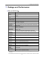
Ratings and Performance ..................................................................................................................... 7-1
(1)
Main unit: ZN-THX11-S□ ......................................................................................................... 7-1
(2)
PC software SD Viewer ES....................................................................................................... 7-2
Appendix ......................................................................................................................................... Appendix-1
List of Displayed Errors .................................................................................................................. Appendix-1
Main Unit: ZN-THX11-S□ .................................................................................................... Appendix-1
PC software SD Viewer ES .................................................................................................. Appendix-2
xii
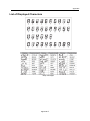
List of Displayed Characters .......................................................................................................... Appendix-3
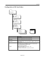
Configuration of SD Card Folder ................................................................................................... Appendix-4
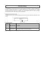
Calibration ...................................................................................................................................... Appendix-5
Dimensions .................................................................................................................................... Appendix-6
Revision History
xiii
1. Product Overview
1. Product Overview
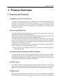
1.1 Features and Functions
(1) High-precision Air Thermo Sensor
Air Thermo Sensor Head ZN-THS1-S allows for the accurate measurement of the
temperature and humidity with a temperature resolution of 0.1C (at 25C) and humidity
accuracy of ±2.5%RH (25C, 10 to 85% RH). The ZN-THS1-S contributes to the
improvement for better quality and management of temperature and humidity through
accurate measurement.
(2) Recording with SD card
The measurement data is accumulated in the internal memory and output as a CSV file to
an SD card by pressing the SET/REC/STOP key.
The internal memory can accumulate approximately 8,500 data, output them to an SD card
without stopping measurement and collect the data when required *1.
In the SD card, the measured data is saved in the folder having a unique name to identify
the Air Thermo Logger. Therefore, even if two or more Air Thermo Loggers are controlled,
the data of each logger can be collected with one SD card while the data in each logger is
normally saved in each internal memory.
Approximately 17 million data items can be recorded (can be stored for 5 years with one Air
Thermo Logger with a measurement interval of 10 sec).
*1: When "SD" blinks in the display of the main unit, do not remove the SD card. Doing so
may damage the data.
(3) Graphical display software provided as standard
The data output to the SD card can be displayed as graphs with the provided PC software
SD Viewer ES. The graphs can be displayed by just specifying the SD card drive on the PC.
The data items of different periods can be connected, and the data items collected from one
or more Air Thermo Logger can be displayed side by side.
(4) Alarm output
The main unit of the Air Thermo Logger has the alarm output terminals. The alarm will
output when the measured differential pressure exceeds upper or lower limit. This function
allows you to quickly handle problems by visualizing the limit of temperature and humidity.
(5) Battery drive
Other than supplying power from the outside, the product can be operated with batteries
(two AAA batteries). The battery drive can last approximately 1 year under the condition with
1-1
1. Product Overview
a measurement interval of 10 minutes, sleep mode and the use of rechargeable nickel metal
hydride batteries.*1 The internal memory is always backed up so that it will not be deleted
after running out of batteries.
*1: The battery life varies according to measurement environment, conditions, and type or
performance of the batteries.
1-2
2. Check and Preparation
2. Check and Preparation
2.1 Checking the Contents
This product includes the following items:
- Main Unit ZN-THX11-S□
- AC Adapter or DC Cable
- Alaram Output Connector
- Utility Disk (CD-ROM)
- Instruction Sheet
- Startup Guide
1
1
1
1
1
1
2.2 Preparing Necessary Items
The following items are required to use this product.
- Fine Differential Pressure Sensor Head ZN-THS1-S
1 (Sold separately)
- SD card (SDHC compatible)
1 (After operation check HMC-SD291 (2 GB))
For saving and moving measured data
- AAA Batteries (for battery operation)
2
Alkaline batteries or rechargeable nickel hydrogen (Ni-MH) batteries
Important
Use two batteries of the same type. Do not mix the old and new batteries.
2-1
2. Check and Preparation
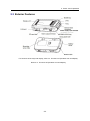
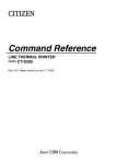
2.3 Exterior Features
Power supply input terminal
For functions of the keys and display, refer to 3. Functions of Operation Unit and Display.
Refer to: 3. Functions of Operation Unit and Display
2-2
2. Check and Preparation
2.4 Input/Output Specifications
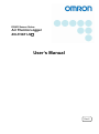
2.4.1 Alarm output
(1) Alarm output terminals
(1) OUT
Outputs the Judgment result allocated in THR mode is output.
(2) GND
It is a common terminal.
Terminal names are inscribed on the unit.
The provided alarm output connector is used for wiring.
(2) Output specifications
Important
Do not directly connect the external power supply between OUT and GND.
Be sure to connect the load.
2-3
2. Check and Preparation
2.5 Assembly
2.5.1 Connecting Air Thermo Sensor
To use this product, an optional Air Thermo Sensor Head ZN-THS1-S is required.
Click
Insert the Sensor Head into the Sensor Head connector until it clicks.
2.5.2 Connecting alarm output terminals
Use the provided alarm output connector to connect OUT and GND to the loads according
to the output specifications.
Refer to : 2.4.1 Alarm output
2-4
2. Check and Preparation
2.5.3 Preparing power supply
This product can be driven by supplying power from the outside or by batteries.
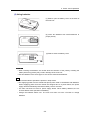
(1) When supplying power from the outside
(1) Insert the plug of the AC adapter or DC cable into the power
supply input terminal.
(2) When using an AC adapter, insert the AC plug of the AC
adapter into an outlet. (100 VAC to 240 VAC).
When using a DC cable,connect the wire with white line on it
to the power(24VDC±10%), and connect the other wire to
0V.
DC power supply
Important
• When using an AC adapter, use the provided AC adapter.
• When using a DC cable, use the provided DC cable.
Note
The main unit does not have a power supply button. When connecting the power supply,
the Air Thermo Station starts operation immediately.
The supplying power from the outside has priority when both the power supply from the
outside and rechargeable battery are used. When supplying power from the outside has
stopped due to a power failure, it will be automatically switched to battery power if
mounted.
2-5
2. Check and Preparation
(2) Using batteries
(1) Slide to open the battery cover on the back of
the main unit.
(2) Insert two batteries with careful attention to
proper polarity.
(3) Slide to close the battery cover.
Important
When inserting the batteries, be careful about the direction of the polarity. Inserting the
battery with wrong polarity may result in damage of the main unit.
Use two batteries of the same type. Do not mix the old and new batteries.
Note
It is recommended to operate the product in sleep mode.
The supplying power from the outside has priority when used in combination with batteries.
When supplying power from the outside has stopped due to a power failure, the power
supply will be automatically switched to battery drive if mounted.
The main unit does not have a power supply button. When battery attached, the Air
Thermo Station starts operation immediately.
Charge the batteries before use. The main unit does not have a function to charge
batteries.
2-6
2. Check and Preparation
2.6 Installing Air Thermo Logger
This section describes how to install the Air Thermo Station.
Important
This product is precision equipment. Do not drop the product when mounting it.
Use the mounting screw hole to secure the product when installing the product to the wall
or equipment where vibration or shock may affect the main unit directly.
2.6.1 Standing installation
Important
When placing the product on the desk, etc., place it enough distance from the edge of the
desk to prevent damage from dropping it. Do not get stuck with the power cable, Sensor
Head cable and LAN cable.
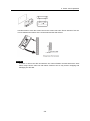
2.6.2 Securing with mounting screws
There are mounting screw holes at the back of the unit to secure the products on the wall or
other surface. The unit also can be secured with round magnets to the screw holes.
M3 screws
Important
The depth of the screw hole is 4 mm. Do not tighten screws more than 4 millimeters. It will
cause the damage to the product.
2.6.3 Mounting with screw hook hole
There are two hook holes below the convex section of the upper unit for the product to be
secured on the wall.
2-7
2. Check and Preparation
Use M3 screws to hook the screw head on the screw hook holes. Set an interval of 2.5 mm
or more between the bottom of the screw head and the wall surface.
Important
To insert or remove the SD card with the Air Thermo Station mounted with screw hook
holes, firmly hold the main unit with hands. Failure to do so may result in dropping and
damaging the SD card.
2-8
2. Check and Preparation
2.7 Preparing Software SD Viewer ES
The Air Thermo Logger is provided with PC software SD Viewer ES that displays the data
recorded with the Air Thermo Logger on the PC.
Fore details on preparation such as installation to use SD Viewer ES, refer to Chapter 6
Display – Usage of SD Viewer ES -.
Refer to: 6. Display – Usage of SD Viewer ES -
2.8 Inserting/removing SD card
The Air Thermo Logger has an SD card slot to record the measurement data and write/read
the setting data.
Important
- When inserting/removing the SD card, firmly hold the main unit with your hands. When the
product is mounted with its screw hook hole, inserting/removing the SD card without firmly
holding the main unit may result in dropping and damaging the SD card.
- When "SD” on the display is blinking, do not remove the SD card. Doing so may destroy
data in the SD card.
- Do not touch the metal terminal of the SD card.
- Do not bend the SD card.
- When inserting/removing the SD card, be aware of static electricity.
- Do not enable the write-protection of the SD card.
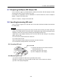
2.8.1 Inserting SD card
“SD” turns ON.
Click
(1) Insert the SD card into SD card slot with the
metal terminal face up.
(2) Insert the SD card until it clicks.
(3) “SD” is displayed on the display.
2.8.2 Removing SD card
(1) Push the inserted SD card as far as possible until it clicks.
(2) When you release your hand, the SD card will come out. Be careful not to drop it.
(3) “SD” on the display disappears.
2-9
3. Functions of the Operation Section and Display
3.
Functions of the Operation Unit and Display
Power supply input terminal
3.1 Control Unit
3.1.1 Control key
Name
MODE key
Item selection key
( key)
Item selection key
( key)
SET/REC/STOP key
Main functions
Switch operating modes.
Release an alarm or an error (press and hold).
Cancel settings before fixing.
Move up the setting items.
Change display screens.
Change setting values (increasing).
Move down the setting items.
Change display screens.
Change setting values (decreasing).
Fix setting values etc.
Start/stop record (press and hold).
Send the recorded data into the SD card.
3.1.2 Reset switch
There is a reset switch at the back of the hole located at the left side of the main unit.
Pressing the reset switch with a thin wire, etc restarts the Air Thermo Logger.
When restarting the Air Thermo Logger, do not touch the front key until the temperature and
humidity is displayed.
Settings are not initialized by the reset.
3-1
3. Functions of the Operation Section and Display
3.2 Display Unit
Display Unit
Display
Meanings of indicators
Meaning and operation when turned on
Recording data in the internal memory.
SD card has been inserted.
SD is being accessed while light blinking.
The measured value exceeds the set threshold value.
The power supply is supplied by the AC adaptor or the DC cable.
The battery level is displayed in 4 levels. Replace batteries when it
blinks
Upper limit threshold
Lower limit threshold
The measurement is processed to extract Max. value.
The measurement is processed to extract Min. value.
The measurement is processed to extract Ave. value.
Current operating mode is set to RUN mode.
Current operating mode is set to FUN mode.
Current operating mode is set to THR mode.
Adjusting the measured values when it is turned on with RUN on.
Current operating mode is SCL when only SCL is turned on.
For alphabets, numerals and major displayed images on the display screen, refer to the
Appendix.
Refer to : List of displayed characters in Appendix.
3-2
4. Setting Air Thermo Logger
4. Setting Air Thermo Logger
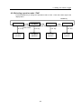
4.1 Setting Procedure and Operation Modes
This section describes the operation and setting procedure of the Air Thermo Logger.
MODE key
RUN Mode
FUN Mode
MODE key
Press 2 times
△▽ key
RUN Mode
operation
THR Mode
MODE key
SCL Mode
MODE key
△▽ key
△▽ key
FUN Mode
operation
THR Mode
operation
△▽ key
SCL Mode
operation
The Air Thermo logger has four operation modes. These modes can be switched with the
MODE key.
To change mode from RUN to FUN, press the MODE key twice. When pressing the MODE
key once, “RUN” blinks. When pressing the MODE key twice, "FUN” blinks to be switched.
Use the and keys to change setting items and display items in each operation mode.
Table: Operation mode
Display
RUN ON
FUN blinks
THR blinks
SCL blinka
Name
Measurement
execution mode
(RUN mode)
Function setting mode
(FUN mode)
Threshold value setting
mode
(THR mode)
Measurement value
adjustment setting
mode
(SCL mode)
Description
Executes measurement and recording of
temperature and humidity.
Makes measurement and recording settings.
Makes settings of threshold values (upper/lower
limits) for an alarm output of temperature and
humidity.
Makes settings of measurement value
adjustment.
4-1
4. Setting Air Thermo Logger
4.2 Settings in FUN Mode
In FUN mode, settings regarding measurement and recording of the Air Thermo Logger are
made.
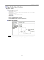
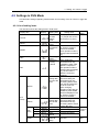
4.2.1 List of setting items
The list below shows the setting items in FUN mode.
Display item
Display
CYCLE
MEAS
MODE
Setting item
Setting value
Measureme
nt value
update
cycle
Processing
mode
Measureme
nt operation
mode
10 s (sec)/20 s/30 s/
1 m (min)/2 m/5 m/10 m
/20 m//30 m/1 h (hour)
Recording
mode
Restore to
factory
default
REC
INIT
Read the
setting data
from the SD
card.
RESTR
ETC
(DISP)
Write the
setting data
into the SD
card.
BCKUP
TIME
(DISP)
YEAR
MONTH
DAY
CLOCK
SDISP
Year
Month
Day
Hour :
Minute
Display
mode at
sleep
4-2
Factoryd
efault
10s
NORM/MAX/MIN/AVE
NORM
NORM/SLEEP
Air Thermo Logger is
reset and restarted
when operation mode is
changed with the MODE
key.
CONT/RING
NORM
When holding the
SET/REC/STOP key,
initialization starts. After
"DONE" is displayed
and operation mode is
changed with the MODE
key, the Air Thermo
Station is reset and
restarted.
When inserting the SD
card and holding the
SET/REC/STOP key,
the setting data is read
from the SD card and is
set to the main unit.
When changing
operation mode with the
MODE key after DONE
has been displayed. The
Air Thermo Logger is
reset and restarted.
When inserting the SD
card and holding the
SET/REC/STOP key,
the setting data is saved
into the SD card.
Year setting
Month setting
Day setting
Hour/minute setting
-
OFF/ON
CONT
-
-
Not
initialized
by INIT.
OFF
4. Setting Air Thermo Logger
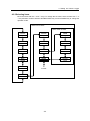
4.2.2 Selecting operation mode “FUN”
Press the MODE key to change the operation mode to “FUN”. “FUN” at the lower right of the
display blinks.
MODE key
RUN Mode
MODE key
Press 2 times
△▽ key
RUN Mode
operation
THR Mode
FUN Mode
MODE key
△▽ key
MODE key
△▽ key
THR Mode
operation
FUN Mode
operation
4-3
SCL Mode
△▽ key
SCL Mode
operation
4. Setting Air Thermo Logger
4.2.3 Selecting items
Move the items with the and keys. To change the set value, select an item with or
key and then confirm it with the SET/REC/STOP key. Press the MODE key to change the
operation mode.
When ETC is DISP
When TIME is DISP.
CYCLE
10s
RESTR
YEAR
2010
MEAS
NORM
BCKUP
MONTH
11
MODE
NORM
TIME
OFF
DAY
17
REC
NORM
SDISP
OFF
CLOCK
14:32
INIT
To
CYCLE
ETC
OFF
4-4
4. Setting Air Thermo Logger
4.2.4 Description of items
(1) Measured update cycle (CYCLE)
Specifies an update interval of measured values.
Selected range (selection type):
10 s (second) / 20 s / 30 s / 1 m (minute) / 2 m / 5 m / 10 m / 20 m / 30 m / 1 h (hour)
Initial value: 10 s
(2) Processing mode (MEAS)
Specifies the calculation method of displayed and recorded measured values.
Selected range (selection type):
NORM / MAX / MIN / AVE
Initial value: NORM
Processing mode
NORM
(Instantaneous
value)
MAX (Maximum
value)
MIN (Minimum
value)
AVE (Average
value)
Measured value
Measured values at each measurement update cycle (CYCLE).
Maximum value of measured values at every 10 seconds during the
measurement update cycle (CYCLE).
Minimum value of measured values at every 10 seconds during the
measurement update cycle (CYCLE).
Average value of measured values at every 10 seconds during the
measurement update cycle (CYCLE).
When the measured value update cycle is 1 minute, the actual measurement is performed 6
times every 10 seconds. When processing mode (MEAS) is set to AVE/MAX/MIN, the
measured values of these 6 are given as the measurement value.
When processing mode is set to MAX/MIN/AVE, “MAX”, “MIN” and “AVE” are turned ON at
lower left of the display.
Note
When MAX/MIN/AVE is specified as processing mode and the operation mode is
switched from “SCL” to “RUN”, the display may keep showing “-----“. This is because the
Air Thermo Logger waits for the necessary data to be accumulated. The estimated time
(which has been set with CYCLE) will be 1 seconds.
4-5
4. Setting Air Thermo Logger
(3) Measurement operation mode (MODE)
Specifies the mode of measurement operation.
Selected range (selection type):
NORM / SLEEP
Initial value: NORM
Measurement
operation mode
NORM
SLEEP
Operation
Normal mode
Sleep mode:
Air Thermo Station operates in power saving mode. The CPU enters
into standby state except when measurement is performed through
measurement update cycles.
If the SDISP, which will be described later, is OFF, even the display
will not be shown. You can press any key to resume the display even
if the display has not been shown. However, when there is no
operation for 5 seconds, the display will disappears again.
It is recommended to operate Air Thermo Station in sleep mode
during battery operation.
Note
Change the measurement mode and press SET/REC/STOP key to confirm. If you change
the operation mode with MODE key, the Air Thermo Logger will be reset to restart.
When the alarm output is ON (including alarm holding state), the power is consumed
even though the Air Thermo Station has been in SLEEP mode. To set the threshold value
to be beyond the assumed range allows unnecessary power consumption to be reduced.
When the display is not shown due to sleep mode, pressing the key can only start it to
show. To execute functions allocated to the key, press the key again after the display is
shown.
4-6
4. Setting Air Thermo Logger
(4) Recording mode (REC)
Specifies the operation for SD card writing during data recording.
Selected range (selection type):
CONT / RING
Initial value: CONT
Recording mode
CONT
RING
Operation
Continue mode
When the internal memory becomes full during recording, a file is
output to the SD card to continue recording. If an error occurs due to
the SD card uninserted, the recording will stop and the data in the
internal memory is maintained.
Ring mode
When the internal memory becomes full during recording, the
internal memory is overwritten from the oldest data to continue
recording.
Note
Press the SET/REC/STOP key (less than 3 seconds) during recording to accumulate the
data in the internal memory up to that point. The data will be output to the SD card as
files while recording continues.
(5) Initialization (INIT)
Initializes the setting values to the factory default (except for year, month, day, hour and
minute).
Operation:
Hold the SET/REC/STOP key to start initialization. It will be completed when “DONE” is
displayed.
After initialization, press the MODE key to change the operation mode. The Air Thermo
Logger will be reset to restart.
4-7
4. Setting Air Thermo Logger
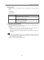
(6) Others (ETC)
Specifies whether or not to display the itmes for the setting files to read/write and time
settngs.
Setting range:
OFF / DISP
Initial value: OFF
Installation value
OFF
DISP
Operation
Not display the items to read/write of the setting data, time setting,
and the display settings in sleep mode.
Pressing the ▽ key after confirmation with the SET/REC/STOP key
returns to the items for CYCLE.
Displays the items to read/write of the setting data, time setting, and
the display setting in sleep mode.
Fix them with the SET/REC/STOP key, then press the ▽ key to
return to the items for RESTR.
(7) Reading setting data (RESTR)
Restore the settings of the main unit by using SD card in which the setting data has been
saved as a backup with BCKUP (described later).
Operation:
Insert the SD card in which the setting data has been saved, and hold the
SET/REC/STOP key. Reading is complete when “DONE” is displayed.
When press the MODE key to change the operation, the Air Thermo Logger will be reset
and restarted.
Note
The number of the setting data items that can be backed up in one SD card is one for one
unit. The setting data that has been backed up with a different Air Thermo Logger can be
restored with other Air Thermo Logger.
When ETC is OFF, setting data cannot be read.
4-8
4. Setting Air Thermo Logger
(8) Writing the setting data (BCKUP)
Saves the setting data of the Air Thermo Logger unit into the SD card.
Operation:
Insert an SD card and hold the SET/REC/STOP key.
Saving is complete when “DONE” is displayed.
Important
The number of the setting data items that can be backed up in one SD card is one for a
unit. If you backup the setting data using the SD card in which the data has already been
backed up, the data will be overwritten. The data will also be overwritten if a backup is
done on another Air Thermo Logger.
Note
• The setting data is written into the system folder of the SD card.
When ETC is OFF, the setting data cannot be written.
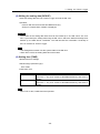
(9) Setting time (TIME)
Specifies the time settings.
Selected range (selection type):
OFF / DISP
Initial value: OFF
Installation value
OFF
DISP
Action
Time cannot be set.
Press the key to fix it with he SET/REC/STOP key and move to
SDISP.
Time can be set.
Press the key to fix it with he SET/REC/STOP key and move to
YEAR.
Note
When ETC is OFF, TIME cannot be specified.
4-9
4. Setting Air Thermo Logger
(10)
YEAR, MONTH, DAY, CLOCK
Sets year, month, day and time.
Setting range (numeric value input type):
YEAR: 2000 to 2099
MONTH: 1 to 12
DAY: 1 to 31
CLOCK: 00:00 to 23:59
Note
When ETC is OFF and TIME is OFF, the year, month, day, hour and minute cannot be
set.
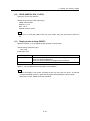
(11)
Display mode at sleep (SDISP)
Specifies whether or not to display during operation in sleep mode.
Selected range (selection type):
OFF / ON
Initial value: OFF
Setting value
OFF
ON
Operation
If there is no operation for 5 seconds during operation in sleep
mode, the display disappears.
When any key is pressed, the display will be restarted.
Continues the display even during operation in sleep mode.
Refer to : 4.2.4 (3) Measurement operation mode (MODE)
Note
When the display is not shown, pressing the key can only start it to show. To execute
functions allocated to the key, press the key again after the display is shown again.
When ETC is OFF, SDISP cannot be specified.
4-10
4. Setting Air Thermo Logger
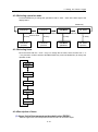
4.2.5 Changing the setting value
There are two specification types: the selection type to select among the predetermined
options, and to input the numeric value.
(1) Changing the setting value of the selection type (Example: Changing
CYCLE)
Press the MODE key for several times to enter FUN mode, and then press the ▽ or △
key to display CYCLE.
Display (upper
line/ lower line)
CYCLE
10 s
Item
Operation
CYCLE
Press the MODE key repeatedly until "FUN" will blink.
Press the or key to display CYCLE in the upper
line of the display.
SET/REC/STOP key↓
Display (upper
Item
line/ lower line)
CYCLE
10 s
↑ blinks
CYCLE
SET/REC/STOP key↓
Display (upper
Item
line/ lower line)
CYCLE
30 s
When pressing the SET/REC/STOP key, the value in
the lower line blinks.
CYCLE
or key↓
Display (upper
Item
line/ lower line)
CYCLE
30 s
↑ blinks
Operation
CYCLE
Operation
Press the or key to display the desired value.
Press the MODE key to cancel the settings.
Operation
Press the or key to display the desired value, and
then press the SET/REC/STOP key.
A value is confirmed and it stops blinking.
After the settings above, has done, the setting items can be changed again with the or
key, as well as the operation mode can be changed again with the MODE key.
4-11
4. Setting Air Thermo Logger
(2) Changing the setting value of the numeric value input type (Example:
Changing YEAR)
Press the MODE key for several times to enter FUN mode, and then press the or key
to display YEAR. To display YEAR, ETC and TIME need to be set to DISP.
Display (upper
line/ lower line)
YEAR
2010
Item
YEAR
SET/REC/STOP key ↓
Display (upper
Item
line/ lower line)
YEAR
2010
↑ blinks
▽ or △ key
Display (upper
line/ lower line)
YEAR
2011
↑ blinks
YEAR
Press the MODE key repeatedly until "FUN" will blink.
“CYCLE” is displayed in the upper line.
Press the or key to display YEAR. To display
YEAR, ETC and TIME need to be set to DISP.
Operation
When pressing the SET/REC/STOP, the least significant
digit in the lower line blinks.
↓
Item
YEAR
SET/REC/STOP key ↓
Display (upper
Item
line/ lower line)
YEAR
2011
Operation
YEAR
Operation
When pressing the or key, the value
increases/decreases.
When holding the or key, the range of
increase/decrease becomes wider.
When pressing the MODE key at this point, the setting
is cancelled.
Operation
Press the or key to display the desired value, and
then press the SET/REC/STOP key.
The value will be confirmed and blinking will stop.
After the settings above, the setting items can be changed again with the or key, as
well as the operation mode can be changed again with the MODE key.
4-12
4. Setting Air Thermo Logger
4.3 Making Settings (Operation in THR Mode)
Set the threshold value regarding the alarm output of the Air Thermo Logger in THR mode.
And set the upper limit and lower limit of temperature and humidity.
When the measured value is whether larger than the upper limit or smaller than the lower
limit during operation in RUN mode, the alarm output terminal turns ON and "ALM" on the
display turns ON.
When returned from the alarm state during measurement, you can set the alarm output state
is maintained can be set.
Note
Alarm monitoring cannot be stopped.
To avoid alarm monitoring, set each threshold value to beyond the assumed measurement
range.
4.3.1 List of setting items
The table below shows a list of setting items in THR mode.
Display
item
DEGHI
DEGLO
RH HI
RH LO
HOLD
Display
Setting item
Function/operation
Upper limit of
temperature
threshold
value
Lower limit of
temperature
threshold
value
Upper limit of
humidity
threshold
value
Lower limit of
humidity
threshold
value
Sets the upper limit of temperature
for an alarm output.
Alarm hold
setting
4-13
Sets the lower limit of temperature
for an alarm output.
Sets the upper limit of humidity for
an alarm output.
Sets the lower limit of humidity for
an alarm output.
Sets whether or not for alarm
output to maintained to be ON
when the measured value returns
to within the range of upper/lower
limit of threshold from the outside
of the range (alarm state) during
measurement in RUN mode.
Factory
default
60℃
-20℃
100%
0%
OFF
4. Setting Air Thermo Logger
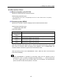
4.3.2 Selecting operation mode
Press the MODE key to change the operation mode to “THR”. “THR” at the lower right of the
display blinks.
MODE key
RUN Mode
MODE key
Press 2 times
△▽key
RUN Mode
operation
FUN Mode
SCL Mode
THR Mode
MODE key
△▽key
FUN Mode
operation
MODE key
△▽key
THR Mode
operation
△▽key
SCL Mode
operation
4.3.3 Selecting items
Move the items with the and keys. To change the set value, select an item with or
key and then confirm it with the SET/REC/STOP key. Press the MODE key to change the
operation mode.
DEGHI
60℃
DEGLO
-20℃
RH HI
100%
RH LO
0%
HOLD
OFF
4.3.4 Description of items
(1) Upper limit of the temperature threshold value (DEGHI)
Sets the upper limit of the temperature threshold value for an alarm output.
4-14
4. Setting Air Thermo Logger
When the measured temperature is higher than the set value, “ALM” and the alarm output
are turned ON.
Setting range (numeric value input type):
-20.0C to 60.0C
Initial value:
60.0C
(2) Lower limit of the temperature threshold value (DEGLO)
Sets the lower limit of the temperature threshold value for an alarm output.
When the measured temperature is lower than the set value, “ALM” and the alarm output
are turned ON.
Setting range (numeric value input type):
-20.0C to 60.0C
Initial value:
-20.0C
(3) Upper limit of the humidity threshold value (RH HI)
Sets the upper limit of the humidity threshold value for an alarm output.
When the measured humidity is higher than the set value, “ALM” and the alarm output are
turned ON.
Setting range (numeric value input type):
0.0% to 100.0%
Initial value:
100.0%
(4) Lower limit of the humidity threshold value (RH LO)
Sets the lower limit of the humidity threshold value for an alarm output.
When the measured humidity is lower than the set value, “ALM” and the alarm output are
turned ON.
Setting range (numeric value input type):
0.0% to 100.0%
Initial value:
0.0%
4-15
4. Setting Air Thermo Logger
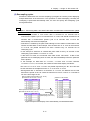
(5) Setting alarm hold
Set whether or not for the alarm output ON state and “ALM” ON state on the display to be
maintained when the measured value is returned to within the range of upper/lower limit of
the threshold value from outside of the range (alarm state) during measurement in RUN
mode.
To release the alarm from the maintained state, hold the MODE key (at least 3 seconds) for
“ALM” to turn off, then the alarm output stops.
Setting range (selection type):
OFF: Maintains an alarm output ON state.
ON: Maintains the alarm output ON state.
Initial value:
OFF
4.3.5 Changing the setting value
Change the value in the same way as changing the settings in FUN mode.
Refer to : 4.2.5 Changing the setting value
4-16
4. Setting Air Thermo Logger
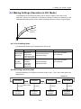
4.4 Making Settings (Operation in SCL Mode)
The adjustment of the measured value of the Air Thermo Logger is set in SCL mode
Adjust the values to be displayed or recorded by adding by adding or subtracting by the
predetermined setting values for the values measured with the Air Thermo Logger (offset).
Display Value
(Adjusted)
Time
4.4.1 List of setting items
The table below shows a list of setting items in SCL mode.
Setting item
Temperature
adjustment
Humidity
adjustment
Display
Upper line:
Measured
temperature
Lower line: Value
after adjustment
Upper line:
Measured
humidity
Lower lilne:
Value after
adjustment
Function/operation
Factory default
Values of the upper and
lower lines are equal.
(not adjusted)
Sets the temperature
adjustment value.
Values of the upper and
lower lines are equal.
(not adjusted)
Sets the humidity
adjustment value.
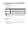
4.4.2 Selecting operation mode
Press the MODE key to change the operation mode to “SCL”. “SCL” at the lower right of the
display blinks.
MODE key
RUN Mode
MODE key
Press 2 times
△▽key
RUN Mode
operation
FUN Mode
THR Mode
MODE key
△▽key
FUN Mode
operation
MODE key
△▽key
THR Mode
operation
4-17
SCL Mode
△▽key
SCL Mode
operation
4. Setting Air Thermo Logger
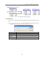
4.4.3 Selecting items
Transition of items can be made with the and keys. To change the set value, select an
item with and keys and then confirm it with the SET/REC/STOP key. Press the MODE
key to change the operation mode.
現在温度℃
Value
after adjustment
調整後の値
Current temperature C
現在湿度%
調整後の値
Current humidity %
Value after adjustment
4.4.4 Description of items
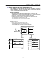
(1) Adjusting temperature
The temperature measurement value is displayed in the upper line, and the value after
adjustment in the lower line.
The value will not be adjusted if in the lower line you set the value after adjustment to the
same as the value currently displayed in the upper line. If a different value is set, the
difference between the values in the upper line and the lower line will be added to the
measured value as an offset. The adjustment range is 10.0C.
When adjustment has been set, “SCL" is ON during measurement in RUN mode.
Setting range (numeric value input type):
-10.0C (Displayed value in the upper line) to +10.0C (Displayed value in the upper
line)
Initial value:
The same value as the measured value (not adjusted)
(2) Adjusting humidity
The humidity measurement value is displayed in the upper line, and the value after
adjustment in the lower line.
The value will not be adjusted if in the lower line you set the value after adjustment to the
same as the value currently displayed in the upper line. If a different value is set, the
difference between the values in the upper line and the lower line will be added to the
measured value as an offset. The adjustment range is 10.0C.
When adjustment has been set, “SCL" is ON during measurement in RUN mode.
Setting range (numeric value input type):
-10.0% (Displayed value in the upper line) to +10.0% (Displayed value in the upper
line)
Initial value:
The same value as the measured value (not adjusted)
4-18
4. Setting Air Thermo Logger
4.4.5 Changing the setting value
Change the value in the same way as changing the settings in FUN mode.
Refer to : 4.2.5 Changing the setting value
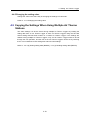
4.5 Copying the Settings When Using Multiple Air Thermo
Stations
The same settings can be the same among multiple Air Thermo Loggers by reading the
setting data from an Air Thermo Logger in other Air Thermo Loggers using the SD card
whose setting data has been written on a certain Air Thermo Logger. If the settings are
shared among multiple Air Thermo Loggers, only one Air Thermo Logger needs to be set
through the unit operation, and the rest of the Air Thermo Loggers can be set by restoring
them. This contributes to less setting time and less miss-settings.
Refer to : 4.2.4 (8) Writing setting data (BCKUP), 4.2.4 (7) Reading setting data (RESTR)
4-19
5. Measurement and Recording
5.
Measurement and Recording
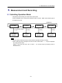
5.1 Selecting Operation Mode
Temperature and humidity are measured in RUN mode.
Press the MODE key to change the operation mode to “RUN”. “RUN” at the bottom right of
the display turns ON.
MODE key
RUN Mode
MODE key
Press 2 times
△▽key
RUN Mode
operation
FUN Mode
THR Mode
MODE key
△▽key
SCL Mode
MODE key
△▽key
FUN Mode
operation
THR Mode
operation
△▽key
SCL Mode
operation
Note
Shift to another mode other than to RUN mode is prohibited during recording.
When mode has been changed from other mode to RUN mode, “-----“ may be displayed
for a long period of time.
(Approx. “time that has been set in CYCLE – 10” seconds when processing mode is
MAX/MIN/AVE.)
5-1
5. Measurement and Recording
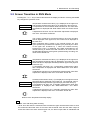
5.2 Screen Transition in RUN Mode
Pressing the or key in RUN mode switches the display as follows. Pressing the MODE
key changes the operation mode.
Measured temperature
Measured humidity
Number of writing
Current time
Measured temperature
Temperature threshold
Measured humidity
Humidity threshold
Temperature measurement value (C) is displayed in the upper line
and humidity measurement value (%) is displayed in the lower line.
If computation for the measured value has been set, the value after
computation is displayed with “MAX”/”MIN”/”AVE” and “RUN” turned
ON.
If adjustment has been set, the value after adjustment is displayed
with “SCL” and “RUN” turned ON.
The number of writings to the internal memory since the recording
start is displayed in the upper line, the current time is displayed in
the lower line.
When measured data is written in the internal memory per time
cycle specified by measurement update cycle (CYCLE), the value
in the upper line increases by 1. When the internal memory
becomes full, "FULL" is displayed. If the data accumulated in the
internal memory is written to the SD card due to an event such as
the SET/REC/STOP key having been pressed during recording, the
value will be cleared to 0.
Temperature measurement value (C) is displayed in the upper line
and temperature threshold value is displayed in the lower line. The
threshold value is displayed alternately between upper limit (Hi) and
lower limit (Lo).
If computation has been set, a temperature measurement value
after computation is displayed with "MAX"/"MIN"/"SCL" and "RUN"
turned ON.
If adjustment has been set, a temperature measurement value after
adjustment is displayed with "SCL" and "RUN" turned ON.
Humidity measurement value (C) is displayed in the upper line and
threshold value is displayed in the lower line. The threshold value is
displayed alternately between upper limit (Hi) and lower limit (Lo).
If computation has been set, a humidity measurement value after
computation is displayed with "MAX"/"MIN"/"SCL" and "RUN"
turned ON.
If adjustment has been set, a humidity measurement value after
adjustment is displayed with "SCL" and "RUN" turned ON.
Returns to the temperature/humidity display.
Note
“REC” turns ON during data recording.
“ALM” turns ON when the measured value exceeds the upper limit threshold value or when
the measured value falls short of the lower limit threshold value and the alarm output is
turned ON. When the alarm hold has been set, the alarm output state is maintained and
5-2
5. Measurement and Recording
“ALM” keeps turned ON even if the alarm state is released. Hold the MODE key for the
maintained alarm.
“MAX”, “MIN” and “AVE” turn ON when processing mode has been set to MAX, MIN and AVE.
They are not displayed in “NORM”.
5.3 Starting/Stopping Recording
5.3.1 Starting recording
When holding the SET/REC/STOP key (for at least 3 seconds) in RUN mode, recordings of
the temperature and humidity start and “REC” turns ON.
The measured data is recorded and accumulated in the internal memory, and is output as a
CSV file into the SD card when the SET/REC/STOP key is pressed.
Important
If a recording starts when the recorded data still remained in the internal memory, the
recorded data will be lost. When pressing the SET/REC/STOP key for less than 3
seconds before recording, the file can be output to the SD card. A state in which the
recorded data remains in the internal memory occurs due to a power failure or the reset
switch being pressed during recording and therefore the Air Thermo Station restarted. If a
recording stop operation is performed properly, the recorded data will not be remained.
In RUN mode, press the or key to display the time at the lower line. If the value in
the lower line is 0, there is no recorded data in the internal memory.
Note
The SD card is not always required to be inserted during recording. However, it needs to
be inserted when pressing the SET/REC/STOP key or stopping the recording.
Shift to another mode other than to RUN mode is prohibited during recording.
5.3.2 Stopping Recording
When pressing the SET/REC/STOP key (for at least 3 seconds) while “REC” is turned ON
during recording, the recording stops and the file is output to the SD card, and “REC” is
turned OFF.
Important
Be sure to insert a writable SD card when recording stops. Though the writing to the SD
card failed, recording will not stop. If the SD card cannot be ready when you want to
change the operation mode due to setting changes, press the reset switch or shut down
the power supply and then restart the Air Thermo Station. Although the data recorded in
the internal memory before a restart will be maintained even after the restart, the data will
be lost after recording starts. Insert the SD card before starting recording and press the
SET/REC/STOP key to output the file.
5-3
5. Measurement and Recording
5.4 Outputting the File to the SD card
The data recorded in the SD card is output to files in the following conditions.
(a) The SET/REC/STOP key has been pressed during recording (less than 3 seconds).
Recording to the internal memory continues.
(b) The SET/REC/STOP key has been pressed during recording (at least 3 seconds).
Recording to the internal memory stops.
Refer to : 5.3.2 Stopping recording
(c) The content of the internal memory has become full. Recording to the internal memory
continues. (Only when the recording mode is set to be continue mode.)
Refer to : 4.2.4 (4) Recording mode (REC)
(d) Not during a recording but the SET/REC/STOP key was pressed when the recorded
data still remains in the internal memory (less than 3 seconds, RUN mode). Such
situation occurs after a restart of the Air Thermo Station due to a power failure or the
reset switch being pressed during recording.
5.5 Releasing the Held Alarm
“ALM” turns ON when the measured value exceeds the upper limit threshold value or when
the measured value falls short of the lower limit threshold value and the alarm output is
turned ON. When the alarm hold setting is ON, the alarm output state is maintained and
“ALM” keeps turned ON even if the alarm state is released.
To release the held alarm, hold the MODE key for at least 3 seconds.
Refer to : 4.3.4 (5) Setting alarm hold
5.6 Hiding the Display
During operation in RUN mode, if no operation is performed in 5 seconds, the display may
disappear. In this case, measurement operation mode is set to be sleep mode and the
sleep display mode is OFF. Recording continues during recording even if the display is not
shown.
Press any key to restart display. Pressing the key when the display is not shown can only
activate the display. To execute functions allocated to the key, press the key again after the
display is shown.
Refer to : 4.2.4 (3) Measurement operation mode (MODE), 4.2.4 (11) Display mode at
sleep (SDISP)
5-4
6. Display – Usage of SD Viewer ES -
6. Display – Usage of SD Viewer ES 6.1 Overview of SD Viewer ES
SD Viewer ES displays the data recorded in the PC as graphs offline with the logging tool,
and displays the data recorded in the SD card in Air Thermo Station unit as graphs. SD
Viewer ES also connects the data items recorded in different periods, and displays side by
side the data items recorded with another Air Thermo Logger.
6.2 Preparation
6.2.1 System requirements of SD Viewer ES
SD Viewer ES operates under the following conditions.
System requirements of SD Viewer ES
Windows XP/Vista/7 (32-bit)
Intel (x86) compatible processor (1 GHz or faster)
1 GB or more (2 GB or more recommended)
Resolution 1024 x 768 or more, 65,535 colors (16-bit
color) or more
HDD
A minimum of 30 GB free space is required to install SD
Viewer ES.
CD-ROM drive
For installation
SD card reader, writer, SD For recorded data reading
card slot
OS
CPU
Memory
Display
6.2.2 Installing/uninstalling SD Viewer ES
(1) Installing SD Viewer ES
(1) Insert the provided Utility Disk into the CD-ROM of the PC. The window below appears.
Click “SD Viewer ES”.
6-1
6. Display – Usage of SD Viewer ES -
(2) When “Security Warning” appears, click “Run”.
(3) In the “Welcome to the SD Viewer ES Setup Wizard” window, click “Next”.
(4) Read the License Agreement shown on the window, and select “I Agree”, and then click
“Next".
6-2
6. Display – Usage of SD Viewer ES -
(5) In the “Select Installation Folder” window, check the installation folder, select “Everyone”,
and then click “Next”.
(6) In the “Confirm Installation” window, click “Next”.
(7) In the “Installation Complete” window, click “Close”. The installation of SD Viewer ES is
complete.
(2) Uninstalling SD Viewer ES
To uninstall SD Viewer ES, click “Add or Remove Programs” (Windows XP), or “Uninstall
program” (Windows 7).
6-3
6. Display – Usage of SD Viewer ES -
6.2.3 Preparing the recording data
Connect a commercially available SD card reader/writer to the PC. This procedure is not
necessary if the main unit of the PC has a SD card slot.
Insert the SD card taken from the Air Thermo Logger in which the recorded data has been
saved into the SD card reader/writer or the SD card slot of the PC.
6.3 Starting and Stopping SD Viewer ES
6.3.1 Starting SD Viewer ES
(1) From the “start” menu of the Windows, select “All Programs” – “OMRON” – “SD Viewer
ES” – “SD Viewer ES Ver.1.00” to start up SD Viewer ES.
Start menu (Windows XP)
You can also click the icon on the desktop to start SD Viewer ES.
Icon
6-4
6. Display – Usage of SD Viewer ES -
(2) After the startup image is displayed for a while, the main window will be displayed.
Startup window
Main window
File
Menu
Open data
Function
Opens recorded data.
Multiple data items can be selected to
specify the display method for either
“connected” or “side-by-side”.
Saves the recorded data.
The data items are saved as one data item
for “connected” or “side-by-side” display.
Exits SD Viewer ES.
Specifies whether or not to display the
toolbar.
Initializes the retained information by each
user such as the window size and time axis
settings.
Displays the version of SD Viewer ES.
Save data
Window
Exit application
Toolbar
Tool
Initialize settings
Help
Version information
6.3.2 Stopping SD Viewer ES
In the menu bar of the main window, select “File” – “Exit application” to exit SD Viewer ES.
If the data has not been saved due to the “tile” display, the message to confirm exiting SD
Viewer ES is displayed.
6-5
6. Display – Usage of SD Viewer ES -
6.4 Opening and Saving Data
6.4.1 Opening data
(1) From the menu bar of the main window, click “File” – “Open Data” to display the “Open
Data” window, and then click the “Add Data” button.
(2) In the “Select additional data” window, specify the SD card in which the recorded data of
the Air Thermo Logger has been saved.
Select “Search folder” and press “Browse” to specify the drive that is allocated to the SD
card (example: E:¥). Check that the check box of “Search Subfolders" is selected, and
then click “Add”.
Item
File
Search folder
Browse
Search
Subfolders
Add
Cancel
Function
Specifies the file.
Specifies all the recorded files in the folder.
Specifies the folder and file names of the recorded data.
Specifies whether or not to browse the subfolder as well when
“Search folder” is selected,
Searches all the recorded files in the SD memory card when the
root folder of the SD memory card is specified on “Search folder”
and the check box of “Search Subfolders” is selected.
Adds the selected recorded file to “Select data:”.
Cancels data addition.
Note
The specific data such as the one saved in the hard disk drive in the PC using SD
Viewer ES can be opened by selecting "File”.
6-6
6. Display – Usage of SD Viewer ES -
(3) On the “Open File” window, select the data to display a graph.
Select the data to open. Multiple data items can be selected. When selecting multiple
items, select the display method from either “Display connected data” or “Display
side-by-side”.
Click “Display Graph” to display the graph.
Only one data item has been saved in the SD card.
Multiple data items have been saved in the SD card
(“Display creating data:+” has been pressed)
6-7
6. Display – Usage of SD Viewer ES -
Select Data
Item
Select
Data
Name
Device
Name
Target
Start Time
End Time
Cycle
Select All
Release All
Add Data
Display connected data
Display side-by-side
Period
Display creating data
Display Graph
Cancel
Hide creating data
Waveform Waveform
to be
Name
created
Device
Name
Target
For "Display waveforms to be created"
Upper Limit
Lower Limit
Included
data
Edit
Resampling cycle
Function
Selects data to be added.
Automatically displays an ID to distinguish the
combination (set) of device name, target, start time
and end time.
Displays the waveform name given when opening data
saved with SD Viewer ES.
Displays the serial number recorded in the recorded
file as a device name.
Displays the target data that is either temperature or
humidity.
Displays the start time of the data recorded in the file.
Displays the end time of the data recorded in the file.
Displays the measurement cycle of the data recorded
in the file.
Selects all the data items displayed in the data
selection column.
Releases all the data items displayed in the data
selection column.
Displays the window to specify the additional data.
Displays the connected data when multiple data items
are selected. Data items that can be connected must
be the same target of the same model.
Displays the data items by overlaying them on a graph
when multiple data items are selected.
Displays start time and end time of the selected data.
Displays the entire period when multiple data items are
selected.
Displays “Waveforms to be created”. Only the
waveform name can be edited by the “Edit” button.
Opens the selected data.
Cancels the data opening operation.
Displays “Waveforms to be created”.
Displays a waveform name. The default is CHx and it
can be changed.
Displays the serial number recorded in the recorded
file as a device name.
Displays the target data that is either temperature or
humidity.
Displays the alarm upper limit.
When the data items are connected and the alarm
upper limits of the data to be connected are matched,
its value is displayed. The value is not displayed if they
are not matched.
Displays the alarm lower limit.
When the data items are connected and the alarm
lower limits of the data to be connected are matched,
its value is displayed. The value is not displayed if they
are not matched.
Displays the ID of the included data when data items
are connected.
Changes the waveform name.
Resamples the data as a dummy with a new cycle
when data items with different sampling cycles are
connected or aligned side by side. Specifies this new
cycle as a resampling cycle. Normally the
automatically calculated value is selected.
6-8
6. Display – Usage of SD Viewer ES -
Note
The waveform name can be changed.
In “Waveform to be created”, highlight the data to change the waveform name and then
click the “Edit” button. Enter the name and click “OK”.
The maximum number of the data items that can be open is 1 million samples.
When the number of waveforms increases, the number of samples per waveform
decreases.
The maximum number of waveforms that can be displayed is 1024.
6-9
6. Display – Usage of SD Viewer ES -
(1) ”Display connected data” and “Display side-by-side”
When displaying the multiple data items that have been recorded with the same Air
Thermo Logger at the same time, the display method can be selected from either
“Display connected data” or “Display side-by-side”.
Display connected data:
Connects the recorded data items and displays them in chronological order.
The data items that can be connected must be the same Air Thermo Logger (same
device name), and the same target type (temperature or humidity).
If a different Air Thermo Logger or type is specified, the data items are tiled.
The connected data can be saved as one file.
The connected data items do not need to be in series.
Display side-by-side:
Displays the recorded data items side-by-side.
The arranged data items can be saved as one file.
The time display of the horizontal axis shows relative time.
データ2
Data
2
データ1
Data
1
温度
Temperature
Temperature
温度
Air Thermo
Sensor
温湿度センサ
湿度
Humidity
Display connected data
Humidity
湿度
Display side-by-side
Waveform
1
波形1
Waveform
1
波形1
Waveform
2
波形2
Waveform
2
波形2
Waveform
3
波形3
Waveform
4
波形4
Time
時間
Time
時間
6-10
6. Display – Usage of SD Viewer ES -
(2) Resampling cycles
Records the data items at a common sampling cycle again as a dummy when displaying
multiple data items at the same time. This operation is called resampling. Normally the
resampling is performed automatically. Also, the user can specify the resampling cycle
among alternatives.
Note
Example 1: Connecting data A and data B that were recorded with a measurement update
cycle of 10 seconds
For example, consider a case where data A recorded for 30 seconds with a
measurement update cycle of 10 seconds from 11:13:04, and data B recorded for 20
seconds with a measurement update cycle of 10 seconds from 11:14:12 are
automatically connected and displayed.
A waveform is created by the plots made starting from the oldest recorded data to the
newest recorded data. In this example, from the start time of 11:13:04 to the end time
of 11:14:42, the plotted waveform has been created every 10 seconds set as
resampling cycle.
In this example a waveform is created with plots made at every 10 seconds of the
resampling cycle between 11:13:04 to 11:14:32.
If data does not exist, the measured value field shows “NO DATA”. If data of the
particular time at resampling does not exist, the data immediately before the particular
time is plotted.
In this example, as data items at “11:13:44”, “11:13:54” and “11:14:04” between
11:13:35 to 11:14:11, do not exist, the measured value fields display “NO DATA”
The hours of “11:14:14” and “11:14:24” are plotted respectively as “B1” and “B2” that
are the data items of the adjacent hours of “11:14:12” and “11:14:22”
Although data “B3” is included in a waveform of “11:14:34”, the data will not be used
because the period of time to create the waveform is from11:13:04 to 11:14:32 that is
out of the time range for B3.
Data データA
A (measured
value update cycle: 10 sec)
(計測値更新間隔:10秒)
(Recorded for 30 sec from 11:13:04)
(11:13:04から30秒間収録)
Time
Waveform
Waveformtotobe
becreated
created
作成される波形
Time
Meas. value
Meas. value
Data
value
update
Data B
B (measured
(measured
value
update cycle:
cycle: 10
10 sec)
sec)
データB
(計測値更新間隔:10秒)
(Recorded
(Recorded for
for 20
20 sec
sec from
from 11:14:12)
11:14:12)
(11:14:12から20秒間収録)
Time
Meas. value
Automatically
connected
自動的に連結
(Resampling cycle: 10 sec)
(リサンプリング間隔:10秒)
Figure Example of the display of the automatically connected data items
6-11
6. Display – Usage of SD Viewer ES -
Example 2: Displays a waveform by connecting data A recorded with a measured value
update cycle of 30 second and data B recorded with a measured value update cycle of 20
seconds
For example, consider a case where data A recorded for 30 seconds with a
measurement update cycle of 30 seconds from 11:13:04, and data B recorded for 40
seconds with a measurement update cycle of 20 seconds from 11:14:02 are
automatically connected and displayed.
In this case a waveform is created by the plots made starting from the oldest recorded
data at the starting time of 11:13:04 to the newest recorded data at the ending time of
11:14:42 in every resampling cycle (10 seconds.)
As the hours “11:13:44” and “11:13:54” have no data, the measured value fields show
“NO DATA”.
An hour without data (such as “11:13:14”) will be plotted by the adjacent hours (for
“11:13:14", the replacement measured value is “A1”, which is the data item at
“11:13:04”).
Data
A (measured
value update cycle: 30 sec)
データA
(計測値更新間隔:30秒)
(Recorded for 30 sec from 11:13:04)
(11:13:04から30秒間収録)
Time
Waveform to be created
作成される波形
Time
Meas. value
Meas. value
Data B (measured
value
update cycle: 20 sec)
データB
(計測値更新間隔:20秒)
(Recorded for 40 sec from 11:14:02)
(11:14:02から40秒間収録)
Time
Meas. value
Automatically
connected
自動的に連結
(Resampling cycle: 10 sec)
(リサンプリング間隔:10秒)
Example 3: Displays waveforms side-by-side for data A recorded with a measured value
update cycle of 30 second and data B recorded with a measured value update cycle of 20
seconds
For example, consider a case where data A recorded for 30 seconds with a
measurement update cycle of 30 seconds from 11:13:04, and data B recorded for 40
seconds with a measurement update cycle of 20 seconds from 11:14:12 are
automatically connected and displayed.
The waveforms will be created from the data at 0:00:00 (relative time), and will be
plotted the recorded time of the data with longer recorded time in every resampling
cycle.
In this example waveforms are created with plots made every 10 seconds of the
resampling cycle for 40 seconds starting from 00:00:00.
The data items of the remaining hours of the shorter recorded time are displayed as
“NO DATA”. In this example, the data of “0:00:40” of waveform A will be displayed as
“NO DATA” since data A is the recording data for 30 seconds.
6-12
6. Display – Usage of SD Viewer ES -
データA value
(計測値更新間隔:30秒)
Data A (measured
update cycle: 30 sec)
(Recorded
for 30 sec from 11:13:04)
(11:13:04から30秒間収録)
Time
Meas. value
Waveform
A to be created
作成される波形A
Waveform
B to be created
作成される波形B
Time
Time
Meas. value
Meas. value
Data B (measured
update cycle: 20 sec)
データBvalue
(計測値更新間隔:20秒)
(Recorded for 40 sec from 11:14:12)
(11:14:12から40秒間収録)
Time
Meas. value
Display
side-by-side
並べて表示
(Resampling cycle: 10 sec)
(リサンプリング間隔:10秒)
Figure Example of side-by-side display
6.4.2 Saving data
You can save the multiple data items to be displayed connected or side-by-side as one data
item.
(1) From the menu bar, select “File” – “Save Data” to display the “Save Data” window. Press
the “Browse” button to specify the folder and file name to save file.
Item
Save to
Browse
Thin out data
Number of
samplings
Save
Cancel
Function
Displays the names of the destination folder and file.
Specifies the names of the destination folder and file.
Select this check box when thinning out the data before saving it.
Displays the number of samples of data to be saved. When “Thin
out data” has been selected, the thinned-out result is displayed.
Saves data.
Cancels data saving.
6-13
6. Display – Usage of SD Viewer ES -
(2) Click the “Save” button.
(3) Click "Save” to save data.
To thin out the data to reduce the file capacity before saving, select the “Thin out data”
check box and specify the thinning rate.
6-14
6. Display – Usage of SD Viewer ES -
6.5 Displaying Graph
6.5.1 Names and functions in the graph window
(1)
(4)
(2)
(3)
(6)
(5)
(1) Recording date (If multiple data items are open, the earliest date is displayed.)
(2) Sampling cycle
(3) Time interval of each scale on the horizontal axis
(4) Waveform name
(5) Vertical axis scale
(6) Right-click menu (ON/OFF to change time axis change and to display max/min/ave.)
List of menu bar items
File
Item
Open Data
Save Data
Print
Print Preview
Exit Application
-
Function
Opens the recorded file.
Multiple data items can be selected and displayed
using tile or cascade display.
The data that has been displayed is closed.
Saves the recorded file.
For tile or cascade display, the data items will be
saved in one file.
Prints the graph.
Check the print image.
Exits SD Viewer ES.
A message to confirm the exit is displayed when
the displayed data has not been saved.
6-15
6. Display – Usage of SD Viewer ES -
Display
Initialize graph
Tile
Cascade
Narrow space
Widen space
Enlarge vertical size
Reduce vertical size
Enlarge horizontal
size
Reduce horizontal
size
Display all horizontally
Cursor
Window
Tool
Help
-
Select
cursor
Hide
Vertical
cursor
Horizontal
cursor
Cursor A&B
Cursor A
Cursor B
Toolbar
Option
Relative
time
Lock
horizontal
grid
Display
scale
Highlight
background
Display help
Version information
-
Returns te graph window to the initial state.
Displays all the waveforms side-by-side with the
reduced size.
Displays all the waveforms overlayed with the
enlarged size.
Narrows the waveform spacing.
Widens the waveform spacing.
Enlarges all the waveforms or selected waveform
in the vertical direction.
Reduces all the waveform or selected waveform in
the vertical direction.
Enlarges all the waveforms in the horizontal
direction.
Reduces all the waveforms in the horizontal
direction.
Reduces the size of waveforms horizontally for
all the waveforms to fit in one screen.
Cursor
Synchronizes A and B cursors.
Calls cursor A.
Calls cursor B.
Enables/disables the toolbar display.
Tool
-
Displays help.
Displays the version information.
List of right-click menu items
Item
Time scale setting
Display Max/Min/Ave
Function
Sets the time axis on the graph.
-
Displays max/min/ave values on the graph.
6-16
6. Display – Usage of SD Viewer ES -
6.5.2 Basic graph operation
(1) Selecting the waveform
Click
Click the tag of the target waveform.
The tage is highlighted and the selected waveform becomes active.
When clicking any location other than the waveform, the selection can be released.
When clicking the waveform while holding the Ctrol key, the multiple waveforms can be
selected.
Click the waveform with holding the Shift key to select all waveforms.
Press the tab key to select the next waveform.
(2) Moving the waveform
Drag
The selected waveform can be moved by a drag.
6-17
6. Display – Usage of SD Viewer ES -
(3) Moving the scale
Drag
Drag the scale to move to any location.
(4) Enlarging/reducing the waveform
Rotating the mouse wheel while pressing the Ctrl key enlarges or reduces the waveform
size.
6-18
6. Display – Usage of SD Viewer ES -
(5) Setting the time axis
Select “Time scale setting” with right-click or click “Time Setting” on the toolbar to set the
time interval in the vertical grid.
(6) Displaying Max/Min/Average values
Max
Average
Min
Values are displayed by
bringing the mouse
cursor near to the graph.
The max/min/average values of the measured data can be displayed in vertical grids.
Select “Display Max/Min/Ave values” with a right-click.
The max/min/average values can be displayed by moving the mouse cursor closer to the
graph.
6-19
6. Display – Usage of SD Viewer ES -
(7) Scrolling the waveform
Scroll bar
Move the scroll bar right and left to view waveforms from the start to end of recording.
(8) Initializing display settings
From the menu bar, select “Display” –“Initialize Graph”, or press “Initialize Graph” on the
toolbar to cancel enlarge/reduce, moving of the scale, etc. to return to the initial state.
6-20
6. Display – Usage of SD Viewer ES -
6.5.3 File menu
(1) Opening data
Opens the data saved with Air Thermo Logger or SD Viewer ES.
Refer to: 6.4.1 Open data
(2) Saving data
Saves the displayed graph.
Refer to: 6.4.2 Save data
(3) Print preview
Displays the print image.
(4) Print
Prints the graph.
(5) Exiting application
Exits SD Viewer ES.
6-21
6. Display – Usage of SD Viewer ES -
6.5.4 Displayed menu
(1) Initializing graph
Cancels enlarge/reduce, scale moving, etc. and returns to the initial state.
(2) Tile/cascade
Tile
Cascade
Multiple waveforms can be displayed side-by-side or overlaid.
From the menu bar, select “Display” – “Tile” to arrange the waveforms side by side.
Select “Display” – “Cascade” to display the waveforms overlaid.
For cascade display, the selected waveform scale is displayed.
Note
While a cascade display is showing, you cannot activate “Narrow interval” and “Widen
interval” command, and “FIX” is shown on the upper right.
6-22
6. Display – Usage of SD Viewer ES -
(3) Narrowing/widening space
Narrow space/
widen space
Narrow or widen the waveform interval.
From the menu bar, select “Display” – “Narrow space” to narrow the space of the waveform.
Selecting “Display” – “Widen space” widens the space of the waveform.
The operation using the keyboard or mouse is also available.
Narrow space: Press the key while holding the Shift key (or mouse wheel operation)
Widen space: Press the key while holding the Shift key (or mouse wheel operation)
Note
While a cascade display is showing, you cannot activate “Narrow space” and “Widen
space” command.
(4) Widening/reducing in the vertical direction
Widen/reduce the graph or waveform in the vertical direction.
From the menu bar, select “Display” – “Enlarge vertical size” to widen the size in the vertical
direction.
Select “Display” – “Narrow vertical size” to reduce the size in the vertical direction.
When a waveform is not selected: Widen/reduce the entire graph.
When a waveform is selected: Only the selected waveform is enlarged/reduced in the
vertical direction.
The operation using the keyboard or mouse is also available.
Reduce vertical size: Press the key while holding the Ctrl key (or mouse wheel operation)
Enlarge vertical size: Press the key while holding the Ctrl key (or mouse wheel operation)
6-23
6. Display – Usage of SD Viewer ES -
(5) Enlarging/reducing in the horizontal direction
Enlarge/reduce the entire waveform in the horizontal direction.
From the menu bar, select “Display” – “Enlarge horizontal size” to widen the size in the
horizontal direction.
Selecting “Display” – “Reduce horizontal size” to reduce the size in the horizontal direction.
Select “Display” – “Display all horizontally” to fit all the waveforms in one screen
These operations can also be performed using the keyboard.
Reduce horizontal size: Press the key while holding the Ctrl key.
Enlarge horizontal size: Press the key while holding the Ctrl key.
Note
From “Tool” – “Option”, a change/lock of “horizontal grid” can be switched.
When [Fix H grid] is selected:
The size of the horizontal grid will not change even if the graph is enlarged or reduced
in the horizontal direction.
When [Fix H grid] is not selected:
The size of the horizontal grid will change when the graph is enlarged or reduced in the
horizontal direction.
The horizontal grid time interval can be set by right-clicking “Set Time Axis”.
When the time interval has been set with “Fix H grid” not selected:
The time interval between horizontal grids will not change even if enlarged or reduced
in the horizontal direction.
When the time interval has been set with “Fix H grid” selected:
The horizontal grid lock will be released when time axis setting is made.
The size of the horizontal grid will not change even if the graph is enlarged or reduced
in the horizontal direction.
When the span of the displayed data is long, executing “Display all horizontally” may turn
the entire graph in gray due to the grid display. In such case, execute “Set Time Axis” to
set the time interval of the horizontal grid wider.
6-24
6. Display – Usage of SD Viewer ES -
6.5.5 Cursor menu
(1) Displaying cursors
Cursor information
window
Drag to move
Cursor A
Cursor B
From the menu bar, select “Cursor” – “Cursor A” to display cursor A.
Selecting “Cursor” – “Cursor B” displays cursor B.
Calling up cursor to display the “Cursor information” window and the position and value that
the cursor is pointed at on the selected waveform.
Drag the cursor by moving the mouse pointer on the cursor.
Note
When cursor information is left blank, a waveform is not selected. Select a waveform to
display the value.
(2) Hiding cursor
From the menu bar, select “Cursor” – “Select Cursor” – “OFF” to hide the cursor.
6-25
6. Display – Usage of SD Viewer ES -
(3) Cursor information
The cursor window appears when a cursor is called.
Name
Select waveform
Cursor A
Cursor B
Cursor A-B
Peak
value between
cursor A and B
Bottom value between
cursor A and B
Average value between
cursor A and B
List
(Vertical cursor only)
“List” button
(Vertical cursor only)
“Copy” button
“Close” button
Function
Displays the selected waveform name.
The waveform name can be displayed as follows.
- “Connection name” waveform name
Displays the position information of cursor A.
- Year month day hour: min: sec (vertical cursor only)
- Value
Displays the position information of cursor B.
- Year month day hour: min: sec (vertical cursor only)
- Value
Displays the difference between cursor A and B
Displays the peak value between cursor A and B
Displays the bottom value between cursor A and B
Displays the average value between cursor A and B
For all the displayed waveforms, displays waveform
name/cursor A/cursor B/difference between cursor A and
B/A-B Peak/A-B Bottom/A-B Average/Unit.
Switches display/nondisplay of waveforms list.
Copys the data of “Cursor Information” to the clip board with a
CSV format.
Closes the “Cursor Information” window.
6-26
6. Display – Usage of SD Viewer ES -
(4) Synchronizing cursors
Cursor A and cursor B can be moved at the same time.
Select “Cursor” – the “Cursor A&B” check box. When the check box is cleared, the cursors
can be moved individually.
(5) Selecting vertical/horizontal curosor
H cursor A
H cursor B
Use of vertical cursor or horizontal cursor can be selected.
From the menu bar, select “Cursor” – “Select Cursor” – “Vertical cursor” to display the
vertical cursor.
Select “Cursor” – “Select Cursor” – “Horizontal cursor” to display the horizontal cursor.
Note
The vertical cursor and horizontal cursor cannot be displayed at the same time.
6-27
6. Display – Usage of SD Viewer ES -
6.5.6 Others
(1) Displaying relative time
Specifies whether or not to display the time of a graph with relative time range.
When it is not selected, the absolute time is displayed. From the menu bar, select “Tool” –
“Option” – “Display Relative Time” to specify.
(2) Fixing horizontal grid
Specifies whether or not to fix the horizontal grid when operating enlarging/reducing graph
horizontally.
When it is not selected, the size can be varied. From the menu bar, select “Tool” – “Option”
– “Fix H grid” to specify.
(3) Displaying scale
Specifies whether or not to display the scale of the all waveforms of the graph.
From the menu bar, select “Tool” – “Option” – “Display Scale”” to specify.
(4) Highlighting the background color
Highlights the background color of the graph.
From the menu bar, select “Tool” – “Option” – “Highlight Background Color” to specify.
6-28
7. Ratings and Performance
7. Ratings and Performance
(1) Main unit: ZN-THX11-S□
Item
Connectable
sensor
Display
Measurement
cycle
Processing mode
Measurement
operation mode
Recording mode
External output
Memory capacity
(internal)
Storage device
(external)
Power supply
Current
consumption
Battery life*5
Operating
temperature
Storage
temperature
Operating
humidity
Storage humidity
Insulation
resistance
Withstand voltage
Vibration
resistance
Shock resistance
Material
Degree of
protection
Mounting method
Dimensions
(WDH)
Weight
(packaged)
Accessories
Content
Air Particle Sensor Head ZN-THS1□□-S
LCD 7-seg 5-digit 2-step display, auxiliary information indicator
display
10s,20s,30s,1min,2min,5min,10min,20min,30min,1h
Instantaneous value, maximum value, minimum value, average value
Normal mode, sleep mode*1
Continue*2, ring*3
Alarm output*4 (Photocoupler output)
Alarm hold is configurable.
Internal memory: Approx. 8,500 data items
SD card with SDHC support (save measured value, save and read
setting value)
DC input: 24 VDC±10%, AC adapter: 100 to 240 VAC/50 to 60 Hz,
Battery: 2 AAA batteries
70 mA max. (AC adapter used)
Approx. 1 year
(2 AAA nickel metal hydride (Ni-MH) batteries, sleep mode,
measurement interval of 10 minutes, and SD card not inserted)
Main unit: 0 to 60C, AC adapter: 0 to 40C
–15 to +60C (no condensation or icing)
20 to 85%RH (no condensation)
20 to 85%RH (no condensation or icing)
20 MΩ (500 VDC)
1000 VAC, 50/60 Hz 1 min
10 to 150 Hz, 0.35 mm double amplitude, acceleration: 50 m/s2 for
each in X, Y and Z directions for 80 min
150 m/s2 in 6 directions (+/-X, +/-Y, and +/-Z directions), 3 times each
ABS
IP30
Screw mounting, hook, floor installation
117.2×24.6×56.8 mm (excluding protruding part)
Approx. 500g
Instruction Sheet, Startup Guide, AC adapter or DC cable*6, alarm
output connector, Utility Disk (CD-ROM)
*1 Power saving mode. The display is always OFF in default setting (It turns ON with button
operation).
*2 Automatically writes data into the SD card when the internal memory reaches the upper
7-1
7. Ratings and Performance
limit, and continues recording until the SD card will reach the capacity limit. If the SD card
is not inserted when the internal memory reaches the upper limit, recording ends. (Data
can be output to the SD card by pressing the button after inserting the SD card.)
*3 A mode to record the latest measurement value for the maximum capacity of the internal
memory at all times. (when reaching the upper limit of the internal memory, data item will
be discarded from the oldest.)
*4 Output when the value exceeds the upper limit that has been set in threshold value setting
mode, or falls short of the lower limit.
*5 The battery life varies according to measurement environment, sampling, measurement
operation mode, battery's type and performance.
*6 AC adaptor is provided to ZN-THX11-S. DC cable and the ferritic core are provided to
ZN-THX11-SA.
(2) PC software SD Viewer ES
Item
Supporting device
OS
CPU
Memory
Display
HDD
CD-ROM drive
SD card reader/writer,
SD card slot
Standard functions
Number of data samples
that can be opened
Number of waveforms that
can be displayed
Content
Air Thermo Logger ZN-THX11-S□
Windows XP/Vista/7 (32-bit version)
Intel (x86) compatible processor (1 GHz or faster)
1 GB or more (2 GB or more recommended)
Resolution 1024 x 768 or more, 65,535 colors (16-bit color)
or more
A minimum of 30 GB free space is required to install SD
Viewer ES.
For installation
For recorded data reading
The following functions are available for Air Thermo Logger:
Displaying waveforms of the recorded data
Displaying multiple recorded data items
connected/side-by-side
Saving the connected/side-by-side data
Up to 1 million samples as a total.
Greater the waveform count, fewer the sample count per
waveform.
1024 at maximum
7-2
Appendix
Appendix
List of Displayed Errors
Main Unit: ZN-THX11-S□
Display
Upper/lower
Contennt
Action to be taken
DATA
E1100
Failed to write
measured data
SEN
E2000
Sensor error
NO SD
E3000
SD card not inserted
BATLO
E3001
Unable to access SD
card
SDLCK
E3002
SD card write prohibited
SD ER
E3003
SD card recognition
error
RESTR
E5000
Invalid setting file data
BCKUP
E5001
Failed to write the
setting file
Failed to write the recorded data to the SD
card due to no free space or card being
removed during writing. Insert the writable SD
card.
Hold the MODE key for 3 seconds or more to
release the error display.
The sensor Head is not connected. Connect
the Sensor Head properly.
SD card is not inserted. Insert the writable SD
card.
Hold the MODE key for 3 seconds or more to
release the error display.
Unable to access to the SD card due to low
battery voltage. Replace the battery or connect
to the AC adapter.
Hold the MODE key for 3 seconds or more to
release the error display.
Writing to the SD card is prohibited. Insert the
writable SD card.
Hold the MODE key for 3 seconds or more to
release the error display.
Failed to recognize the SD card. Insert an
appropriate SD card.
Hold the MODE key for 3 seconds or more to
release the error display.
The setting data within the SD card is invalid
due to invalid model type or setting value.
Hold the MODE key for 3 seconds or more to
release the error display.
Failed to write to the SD card of the setting file
due to no free space or writing prohibited.
Insert a writable SD card.
Hold the MODE key for 3 seconds or more to
release the error display.
Appendix-1
Appendix
RESTR
E5002
Failed to read the
setting file
HARD
E****
Hardware error
There is not setting file in the SD card. Insert
the SD card in which the setting file has been
written.
Hold the MODE key for 3 seconds or more to
release the error display.
There may be a hardware error. Please contact
the distributor or OMRON representative office
to inform the displayed error code.
PC software SD Viewer ES
Message
”You cannot add data of more than
10000 data items.”
”Waveforms of more than 1024 cannot
be displayed.”
Action to be taken
Too many data items selected in “Open Data”.
Execute “Open Data” on the menu again and
select only the data that you want to display.
The number of waveforms that can be
displayed on one graph is 1024. Narrow the
data that you want to display and execute
again.
The number of data items exceeds 1 million
samples. Setting the resampling cycle longer
may allow the data to be displayed.
“All the waveforms cannot be displayed
due to too much data amount. Is it OK
to display data in the following span?”
Even the non-data period is treated as data
called “NO DATA” per sampling cycle and the
number of samples is counted inside. On the
“Open data” window – “Select Data” – the
“Select” column, select data item individually to
reduce the non-data period.
“Data cannot be found because the
necessary data has been broken or
deleted.”
Saving cannot be performed because the data
necessary for file saving does not exist. Redo
the operation from opening the recorded data.
The data necessary to display graph is not
recorded. Check that the recorded data has
not been edited and specify the data again.
Data cannot be open when the recorded data
is open with software such as Excel. Exit other
software and read the data again.
“The following file could not be read.”
Appendix-2
Appendix
List of Displayed Characters
Major messages
Appendix-3
Appendix
Configuration of SD Card Folder
/
Root folder
_FARM
System folder
SYSTEM
System folder
[Serial No]
Folder for
recorded data
[Y/M/D]
[年月日]
(20000101
to
20991231)
File/folder name
_FARM
SYSTEM
“Serial No”
“Y/M/D”
Recorded
data (CSV
file)
Content
For system.
Do not change the file name or internal file.
For system.
Do not change the file name or internal file.
Folder to store recorded data.
The serial number of the Air Thermo Logger is used for the
folder name.
Subflder to store recorded data.
Recorded date (YYYYMMDD) is used for the folder name.
The recorded data file is CSV format.
The file name is as follows.
“Hour, minute, second + serial No” .CSV
Example: 12345601.CSV
Recorded data file written to the file at 12:24:56.
Appendix-4
Appendix
Calibration
Calibration is not required for the Air Thermo Logger unit.
The Air Particle Sensor Head (ZN-THS1-S) is needed to calibrate. Read the Instruction
Sheet of the Sensor Head.
Appendix-5
Appendix
Power supply input
terminal
Dimensions
Appendix-6
Revision History
The specifications of this product you have just purchased are subject to changes in adding new
functions or making improvements. This operation manual will be revised whenever such changes
incur with the changes reflected on its contents. The revised manual contains the history of revision
with the manual revision codes and the revision descriptions.
About the manual revision code
The manual revision code is affixed to the tail of the “Rev. No.” given in the lower right corner of the
manual.
Rev.□
Revision code
History of Revision
Revision
Date
code
Description of revision
A
December 2010
First edition
B
June2011
Addition of DC cable model
C
February2012
Power-supply-voltage clerical error correction
As of February 2012 (WEB Ver.3)