1
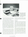
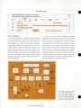
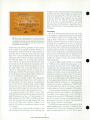
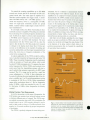
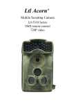
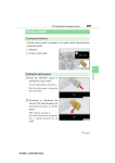
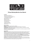
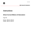
HEWLETT-PACKARDJOURNAL
AUGUST1971
© Copr. 1949-1998 Hewlett-Packard Co.
Lilliputian Measuring System
Does Much, Costs Little
A mainframe costing less than $400, a choice of four functional snap-on
modules including a 500-MHz counter, and an unusual battery pack are the
elements of this rugged, portable, MOS/ LSI/ LED instrument system.
By Ian T. Band, Hans J. Jekat, and Eric E. May
NOT VERY MANY YEARS AGO electronic counters were
strictly laboratory instruments. Nobody needed their
kind of precision in frequency and time measurements
anywhere else. Today, however, what used to be labora
tory precision is now commonplace in all kinds of equip
ment, and as a result electronic counters are in demand
as general-purpose service and maintenance tools.
One only has to look at the communications industry
to see what's happened. The crowded electromagnetic
spectrum has been squeezed to make room for more and
more channels. To guarantee that each transmitter re
mains within its allocated channel, its frequency must be
controlled to within a few parts per million. Measuring
frequency with this degree of accuracy requires an elec
tronic counter. Or look at the vast network of telephone
cable and equipment, over which millions of messages
are transmitted daily. To keep it in working order, carrier
frequencies must be measured and calibrated. Tone bursts
must be counted. Millions of relays must be checked and
timed. These are jobs for electronic counters.
The kind of counter that's needed for service and
maintenance is quite different from the usual laboratory
type. It has to be simple, rugged, and reliable. It has to
be portable — even battery powered — since the equipment
to be serviced is likely to be a communications link on
a distant hilltop or the navigational equipment aboard
a ship. It has to be low enough in cost to be considered
a general service tool. And it has to have sufficient mea
surement capability to fill the majority of service and
test needs.
Mini-System
Hewlett-Packard's answer to these requirements, the
5300 Measuring System, is equally at home on the lab
P R I N T E D
I N
bench or in a maintenance van. Calling it a system may
seem a bit pretentious, since it's the smallest of HP's
counters. Yet its modular design gives it versatility and a
repertoire of measurement capabilities that many fullsize instruments don't have, including frequency mea
surements to 500 MHz, 100 nanosecond time-interval
resolution, autoranging, and battery operation. The 5300
system is one of the first of the new breed of instruments
that rely heavily on the newer technologies: MOS, largescale integration, solid-state light-emitting-diode displays,
high-speed bipolar integrated circuits, read-only memo-
Cover: You probably
wouldn't find a 5300 Measur
ing System among a moun
tain rescue team's standard
equipment. But one could be
used at the base camp for
checking vital radio equip
ment. Shown here is all it
takes: a 5300A mainframe, a
5310 A battery pack, a 5303A
500 MHz counter module,
and a makeshift antenna.
In this Issue:
Lilliputian Measuring System Does
Much, Costs Little, by Ian T. Band,
Hans J. Jekat, and Eric E. May
page 2
A Package for Portability and Ser
v i c e a b i l i t y
p a g e
An Almost All Solid-State Strip-Chart
Recorder, by Charles K. Michener
U . S . A .
© Copr. 1949-1998 Hewlett-Packard Co.
9
page 13
Fig. 1. Compact, low-cost 5300
Measuring System consists of
a mainframe (top half of instru
ment at left), tour snap-on func
tional modules, and a battery
pack (right). Autoranging, serial
BCD digital output, and a highstability crystal reference oscil
lator are standard.
ries, and thin-film hybrid circuits. From the combined
advantages of all these technologies this mini-system de
rives a level of performance that couldn't have been
achieved at such low cost just a few years ago.
Modular design is apparent in the system photograph,
Fig. 1. The heart of the system is a six-digit counter
mainframe, Model 5300A, which can be combined with
any of several functional modules to meet specific appli
cation needs. The first four functional modules are now
available (see table, page 4). There's a low-cost 10 MHz
autoranging counter (Model 5301 A), a wideband 500
MHz counter (Model 5303 A), a 50 MHz general-pur
pose universal counter (Model 5302A), and a precision
timer-counter specifically optimized for timing measure
ments (Model 5304A). Any combination of mainframe
and module can be instantly adapted for battery opera
tion by inserting a rechargeable battery pack (Model
5310A).
The benefits of modular construction are considerable.
Modularity makes it possible to choose from a wide range
of measurement functions, but to have at any one time
only those functions necessary to do the job, without the
extra cost, complexity, and power consumption (in this
case, battery drain) of unused functions. If and when a
need arises, new capability can easily be added to the
system by adding more functional modules. Adding these
only when they are needed assures the user of always
having the latest in measurement capabilities at minimum
cost. Another economic advantage is that the mainframe
can be produced in relatively high volume, thereby bring
ing its cost down.
The Mainframe
The mainframe of the 5300 system is the upper half of
the instrument. All the elements necessary for a complete
10-MHz six-digit counter are contained in this main
module. It houses the solid-state display for the system,
all the basic counting, storing, and timing logic, a highstability 10 MHz crystal-controlled reference oscillator,
and all the functional control logic for precision counting
and timing. All the power for the system is provided by
the high-efficiency switching power supply in the main
frame.
By itself, the mainframe can perform no measure
ments. The bottom half of the instrument, the snap-on
functional module, calls upon the mainframe's capabili
ties as needed for the particular application. This parti
tioning of capabilities maximizes the flexibility of the
system. In the simplest case, the 10 MHz counter, the
snap-on module consists merely of an input amplifier
and trigger circuit to convert a low-level input signal to a
good logic-level signal for the mainframe, plus a hard
wired program to tell the mainframe what to do with the
signal.
© Copr. 1949-1998 Hewlett-Packard Co.
System Architecture
The 5300 is designed as a system from the ground up.
The system approach is evident in the architecture of the
mainframe. The block diagram, Fig. 2, shows the main
frame coupled to a typical snap-on module. All data is
transmitted one digit at a time (digit serial) on a four-line
data bus. Data can be moved from the mainframe to the
module and vice versa and from either location to the
front-panel display and to the rear-panel recorder output.
The flow of data is controlled by a set of address codes
which can be manipulated by the snap-on module. Coded
signals are also used to program the output frequencies
from the time base.
In a low-cost counter, this bus-oriented architecture
represents a radical departure from the past. It's signifi
cant that the basic block diagram of a counter has re
mained relatively unchanged for the last ten years,
surviving the major upheavals of technology from vacuum
tubes to transistors to medium-scale-integrated circuits.
Now, however, with the advent of large-scale-integrated
(LSI) circuits, a break from tradition seems overdue.
When a few dozen extra transistors become insignificant
compared with the cost of a few extra pins on an 1C
package, design rules can easily be changed. In the 5300
system the change was towards a greater emphasis on
signal multiplexing and automatic operation.
Fig. 2. Systems design results
in a block diagram that's dif
ferent from other counters. All
data is transmitted one digit at
a time on a four-line data bus.
The snap-on module determines
the function of the instrument.
© Copr. 1949-1998 Hewlett-Packard Co.
The system approach resulted in reduction of all the
counter logic to a simple combination of only five integrated-circuit packages (see Fig. 3), corresponding to
the five basic blocks of the block diagram, Fig. 2. Inside
each of these packages, however, is a very complex array
of circuitry.
cuit is capable of counting rates in excess of 10 MHz. The
chip measures 96 mils by 118 mils (Fig. 4). It contains
930 transistors, but consumes only 300 mW. It's an
excellent example of the advantages of MOS/LSI over
bipolar IC's: lower package count, lower power con
sumption, and fewer interconnections to cause reliability
problems.
The LSI Circuits
Two of these packages in particular represent a signifi
cant advance in 1C technology. The counting circuitry
and the time-base dividers have always imposed a limita
tion on any counter-based instrument in terms of per
formance, cost, size, and power drain. In the 5300
system, two small 16-pin packages containing MOS/LSI
chips have replaced what was previously half of the
instrument.
Fig. 4. 70 MHz MOS/LSI six-digit counter circuit and
eight-decade time base chips. Counter chip (top) is 0.096
in by 0.118 in and contains 930 transistors. Time base
is 0.109 in square and contains 980 transistors.
Fig. 3. Mainframe contains a complete six-digit 10 MHz
electronic counter except tor an input amplifier and
trigger. Large-scale and medium-scale integration and
a solid-state display reduce the six major blocks in Fig.
2 to ¡ust six components. Benefits are reliability, service
ability, and low power consumption.
A six-digit counter like the 5 3 00 A requires a sixdecade counting circuit and six decades of data storage.
The most common way of implementing such a circuit
today would be with twelve TTL integrated-circuit pack
ages. However, in the 5300A all six counting decades
and six storage registers are on a single integrated-circuit
chip in a 16-pin ceramic package. This metal-oxidesemiconductor (MOS) large-scale-integrated (LSI) cir
The MOS process used by HP is low-threshold p-channel MOS. 10 MHz speeds had never been achieved with
this process before the six-decade counter chip was de
veloped. The high speed comes from a combination of
factors.1 First, the transistors in each of the six decades
are made only as large as necessary for the counting rate
at which they had to operate. Only the first binary of the
first decade actually has to operate at 10 MHz. Second,
geometries are reduced to minimize capacitance. Channel
lengths are 2.5 ¡>.m after side diffusion and gate metal
overlap is 1.25 ,/im before diffusion. Third, the need for
interconnecting metallization is minimized by a unique
'ground riveting' process (see Fig. 5). What this tech
nique does is eliminate all unnecessary ground lines to
the sources of the MOS transistors. An N-f- region is
diffused next to the P+ source diffusion and the two
diffusions are connected by metal. This connects the
source to the substrate, the other side of which is con-
© Copr. 1949-1998 Hewlett-Packard Co.
changed from the traditional divider chain. One change
is that the time-base output frequency is selected on the
chip and is programmed by a three-wire select code to
divide the time-base input frequency by any decade
factor from 10 to 10s. However, the major distinction
from all previous counting instruments is the second
time-base output which produces a logarithmic train of
pulses. This is the key to the autoranging feature of the
instrument.
Autoranging
Fig. 5. Extra N + diffusion next to P+ source, and extra
N + guard band, are elements of a unique 'ground rivet
ing' scheme that was used to eliminate much ground
metallization. This reduced the sizes of the MOS chips
and allowed 10 MHz speeds.
nected to the case, which is grounded. A source riveted
in this manner is not actually grounded. However, it's
separated from ground only by the series resistance of
the source pad. To reduce this series resistance a guard
band of N+ material is diffused around the entire chip.
This reduces the series source resistance to approximately
800 ohms per square mil. A load-to-source resistance
ratio of 100 to 1 is used to assure sufficient noise rejec
tion and the sizes of the source pads are adjusted accord
ingly. Using the riveting method throughout the circuit,
the design engineer for all practical purposes has the
freedom to forget ground lines. He no longer has to
provide space for them. This, of course, reduces the size
of the chip and increases the speed. Direct counting rates
of 12.5 to 20 MHz are consistently achieved.
In a typical six-decade counter with digit-parallel
binary-coded-decimal readout there are 24 outputs to
the display driver. This is too many for a compact pack
age, so in the 5 3 00 A a strobed readout is used: the digits
are read out one at a time on the same four lines. Three
input lines control the digit to be read out and the timing
of the readout. Thus the 24 lines are reduced to seven.
The time-base divider in the 5300A is also a single
MOS/LSI chip measuring 109 mils square and contain
ing 980 transistors (see Fig. 4). It also operates at 10
MHz, consistent with the 5300A's 10 MHz crystal oscil
lator. The time base chip has eight decades; thus it can
divide the 10 MHz crystal oscillator frequency by as
much as 100 million, to provide gate intervals as long
as 10 seconds.
To reduce the pin count and take advantage of the
LSI technology, the architecture of the time base was
One of the major features built into the LSI circuits
is the capability of making measurements automatically,
so the operator doesn't have to change ranges. Auto
ranging, which is built into the mainframe, allows the
display to be filled for maximum resolution, but prevents
the display from overflowing. In the case of a frequency
measurement, this means automatically selecting the opti
mum gate time. For a period-average measurement, the
optimum number of periods to be averaged is selected. In
either case the decimal point is positioned automatically
and the correct measurement units are displayed. Three
of the four snap-on modules make use of this feature to
simplify the function controls and provide foolproof
hands-off operation.
Let's take a simple example (see Fig. 6). A frequency
of 5 MHz is to be measured in the auto mode. As the
measurement proceeds, cycles of the 5 MHz signal are
accumulated in the counting circuits. The measurement
will be terminated after a precise measurement time — for
example, one second — to give a total count that can be
interpreted as cycles per second or hertz. The measure
ment time is determined by the time base. In one second,
however, the 5 MHz signal would overflow the capacity
of the six-digit display; therefore, a shorter measurement
time must be selected. In this case, a 0.1 second gate time
would give an accurate six-digit count of 5.00000 MHz.
Any shorter gate time, such as 0.01 second, would give
a valid reading but would not completely fill the display.
As the measurement progresses, the autoranging cir
cuits detect when the first five digits of the display have
been filled, or more exactly, when a count of 90.000 is
reached. In the case of the 5 MHz signal, this would be
after 0.018 second. The next valid measurement time is
then selected, in this case, 0. 1 second. The measurement
time is always restricted to decade steps.
The MOS time base provides all the necessary timing
signals beginning with a start pulse to initiate the mea
surement. This is followed by a succession of valid stop
pulses at decade intervals of 1 //.s, 10 ¿us, 100 /is, and so
© Copr. 1949-1998 Hewlett-Packard Co.
Logarithmic
Timing Pulses
From Timebase o i ,,s 10 ..$ 100 »s 1 ms 10 ms 100 ms Is 10 s
Fig. 6. Autoranging selects the
gate time lor maximum resolu
tion without overflowing the dis
play. A logarithmic output from
the time-base chip produces
pulses at decade multiples of 1
us. The counter counts until the
fifth decade reaches a count of
9, then terminates the measure
ment on the next logarithmic
pulse. Manually-selected gate
times are also available.
Logarithmic Time Scale
oranging With a 5-MHz Input Signal
on up to 10 seconds. Every stop pulse is precisely timed
in relation to the same start pulse. All these timing signals
are generated at a single output terminal of the time base
and are synchronized with the clock frequency so that
propagation-delay errors are cancelled. Since all possible
stop pulses are available on a single line, it's a simple
matter for the autoranging control circuits to select the
first available stop pulse following the 90,000 count. To
position the decimal point and units correctly, the mea
surement range is determined by counting the number
of stop pulses which occurred before the display was
filled. In the event that the frequency is too low to fill
the display in a reasonable time, an arbitrary limit of one
second is set on the measurement time. (Longer gate
times can be selected manually. )
Let There Be (Solid-State) Light
The display of the 5300 system is another departure
from the past. A light-emitting-diode (LED) display was
chosen as a step towards all-solid-state reliability. Low
voltage drive, low power drain, and an in-plane wideviewing-angle display were other benefits of the LED
approach.
Each digit of the display is formed by a 4 x 7
matrix of red-light-emitting gallium-arsenide-phosphide
(GaAsP) diodes (Fig. 7). Characters of this type have
more esthetic appeal than the simpler and more common
seven-segment type of display. An added advantage of
the dot-matrix approach is redundancy: if a failure oc
curs in any one diode, the character cannot be misinter
preted as a different digit. The 5300 display contains all
six 4 x 7 arrays on a single ceramic substrate.
In keeping with the one-digit-at-a-time data transfer
in the instrument, the display is scanned rather than con
tinuously lighted, only half a digit being lit at any time.
However, the entire display is scanned 1,000 times every
second so the display appears steady. Since each diode
can be on for only 1/12 of the total time, its instantane
ous brightness must be 12 times higher than a static dis
play. This turns out to be an advantage with LED's since
the gallium-arsenide-phosphide diodes have a higher effi
ciency at high currents. Thus although the peak current
is high, the average current and power required are less
than would be needed for a static display of the same
brightness. The power saving is particularly important
when the battery pack is being used.
Measuring Frequencies to 500 MHz
Although the 5 3 00 A mainframe can count only to 10
MHz, the snap-on modules can greatly extend this range.
The upper frequency limit at present is 500 MHz and is
reached by adding the 5303A module. The 5303A prescales the 500-MHz input signal; that is, it divides the
input frequency until it is within range of the 10-MHz
mainframe counting logic.
Fig. 7. Data comes out of the counter chip one digit at
a time, so the solid-state display is scanned instead of
continuously lighted. One-half digit is lighted at a time.
A scan is completed every millisecond, so the display
appears steady.
© Copr. 1949-1998 Hewlett-Packard Co.
To extend the counting capabilities up to 500 MHz
several new circuits had to be developed in HP's inte
grated circuit labs. The input signal is amplified by a
thin-film hybrid amplifier and trigger circuit. A mono
lithic 500 MHz binary and a 250 MHz quinary (-f-5)
divide the frequency down to a manageable 50 MHz.
These two high-speed monolithic circuits are special
EECL (emitter-emitter coupled logic) circuits with twolayer metallization.2
In a six-digit counter, the effect of prescaling on mea
surement accuracy is negligible. Prescaling can sometimes
be an advantage for measuring frequency-modulated sig
nals. To fill all six digits in a direct-count measurement,
a 500-MHz carrier frequency can be measured to sixdigit accuracy in 1 ms with 1 kHz resolution. The same
measurement with the 5303A takes 100 ms, since the
input is first divided by 100. But people don't respond
to changes in the display much faster than 10 times per
second, so the difference in the number of readings per
second is undetectable, and the longer measurement time
allows the errors due to frequency modulation of the
carrier to be averaged out.
A typical application of the 5 3 03 A would be calibra
tion of a mobile transmitter at frequencies just below 500
MHz. These transmitter frequencies must be maintained
within an accuracy of 5 parts per million, which would
be about 2.5 kHz maximum error. To measure the trans
mitter frequency the 5300A/5303A can be placed a few
yards away from the transmitting antenna with just a
small vertical whip antenna connected to its BNC input
terminal. The 0.1 s range can be used for a rapid but
coarse adjustment to ± 1 kHz. A finer adjustment can
be made by allowing the most significant digit of the dis
play to overflow in a 1 or 10 second measurement, giving
a resolution of 100 Hz or 10 Hz. Other measurement
ranges allow resolutions down to 1 Hz for frequencies
below 50 MHz — which are prescaled by only 10 — and
0.1 Hz below 10 MHz, where frequencies are directly
counted.
surements, but it is limited to measurements between
the leading edges of two different signals. Its two input
amplifiers are ac coupled. For better precision in timing
measurements, the 5304A module is more useful. It can
measure time between any two points on the same signal,
and it can select the precise voltage at which triggering
occurs, on the leading edge or the trailing edge of posi
tive or negative signals. Its two matched de-coupled input
amplifiers have bandwidths of 0-10 MHz; they can also
be ac coupled for measurements of signals with large dc
offsets. In addition to timing events, the 5304A can make
measurements of pulse widths, rise times, and other in
tervals between precise points on a waveform.
And that's not all. Besides selecting the exact trigger
point on an input waveform the 5304A can select which
section of a waveform will trigger the stop channel. This
is the function of its delay control, which allows it to
perform measurements that are beyond the capabilities
of most other timer-counters.
— «-I l-« — Normal Measurement Time
asurement Time
With Delay
Gate Open
Relay Timing Measurement Using Delay Control
Start
C h a n n e l
T r i g g e
Level J
.
r
â € ¢ â € ¢
i
T r i
i i
^
g
S t o p
g e r
v
C h a n n e l
L e v e l
=n ^ " —^2 — . 1L -_: tr — ~ — _z¡
Delay A
Measurement A
I Delay B I
Making Precision Time Measurements
As well as measuring a wide range of frequencies, the
5300 system can measure time intervals between events
or between different parts of a signal. The 5302A snapon module can measure time with 100 ns resolution. Its
normal range is up to 1,000 seconds, although it can be
used to time events as long as 10 million seconds (four
months) to 10 second resolution by proper interpretation
of the display.
The 5302A is perfectly adequate for most timing mea
© Copr. 1949-1998 Hewlett-Packard Co.
 «
â € ”
-
-
.
Measurement B
_ _
i Mee a s u r e m e n t C
Using Delay Control To Select Trigger Point
Fig. 8. Model 5304A Timer/ Counter snap-on module is
optimized for time-interval measurements. It has 100-ns
resolution and an unusual delay feature which causes
the counter to ignore extraneous events and measure the
interval of interest. Delay is useful for relay timing and
tone-burst measurements.
A Package for Portability and Serviceability
The packaging of the 5300 system is a good example of
today's demands on human engineering and industrial de
sign. The package had to be rugged, portable and service
able, as well as have high performance and low cost. The
approach taken features a cast aluminum case for ruggedness and RFI shielding*, snap-on modules rather than
plug-ins, and snap-together assembly for serviceability
without a screwdriver. The units are portable, stackable,
and rack-panel mountable.
The snap-on concept was used for several reasons. First,
there is no repackaging. A normal plug-in unit requires its
own package which then must be ¡nsertable into a main
frame package. In the 5300 system, the snap-on module is
simply a bottom half identical to the mainframe top half, and
together the two make up one complete package. In addi
tion, there can be an in-between module, like the batterypack, which fits between the mainframe and the snap-on
module. In concept, the counter could be expanded in
definitely with a whole series of center modules. Another
advantage is that each snap-on and in-between module has
its own rear panel which can change depending on its func
tion.
The package consists of two half-shells which snap to
gether with two integral sliding latches. The shell serves not
only as a covering but as a chassis and RFI shield, since
it is made of cast aluminum. There is no sheet-metal chassis
as such; the extensive use of LSI circuits and 1C packages
has made it possible to put all the circuitry in each module
and the mainframe on one main PC board. The PC board
and the front- and rear-panel assemblies snap into a set of
plastic clips in the casting. This allows instant assembly
or disassembly for servicing.
The case is designed for portability. It is small and
shaped so it can be carried readily in one hand. This makes
it easy to move around a bench; there's no bothersome
handle to fold out of the way. Other units can be stacked
on the case. A tilt stand attached to the front feet is useful
for normal bench viewing, or it can be attached to the rear
feet for easy viewing when the counter is placed on top of
a cabinet or shelf.
For complete portability the power cord is disconnected
and the battery pack is added between the mainframe and
its functional snap-on module. There are handles on the
sides of the battery pack, and there's a shoulder strap for
Making Delayed Timing Measurements
The front-panel delay knob controls a time delay
which begins at the instant the start channel is triggered.
Until the time delay has expired, the stop channel cannot
be triggered. This allows the end point of the measure
ment to be selected in much the same way as the delayed
sweep on an oscilloscope allows a selected portion of a
signal to be displayed.
The delayed time-interval capability is particularly
useful for relay timing measurements, in which relay con
tact bounce usually imposes a measurement problem (see
carrying the counter or for draping it around one's neck
for hands-free operation. The rear of the instrument has no
protrusions, so it can stand on end while on battery power.
Vacuum-formed dust covers are provided with each snapon module to protect them and allow easy stacking when
not in use. Although designed for bench use and portable
operation the counter can be rack mounted in a standard
19 in rack panel, or mounted as a 1/2 module in a com
bining case.
— .'me
- Sliding Latches
I
Front Panel
Rear Panel
--sS.i--~r_.-^
¿ Wgr3 v^--
1 * r -
Plastic Fasteners-
Aluminum Case
•The cast aluminum case is a far better shield than most instrument
cases. RFI itself, however, it isn't a complete RFI shield. Complete RFI
shielding of the 5300A would require a metal screen behind the plastic
front panel of the mainframe.
Fig. 8). Instead of measuring the correct time during
which the relay is closed, most timer-counters would
measure only the duration of the first bounce, terminat
ing the measurement when the signal first passes through
the trigger voltage selected for the stop channel. With the
5304A, however, the contact bounce can be ignored by
adjusting the delay to be longer than the bounce period.
Thus the true time interval until the contacts are opened
again can be measured. The bounce time can also be
measured, by increasing the delay slowly and measuring
the time to each bounce. A delay output and a gate out-
© Copr. 1949-1998 Hewlett-Packard Co.
put, available at rear-panel connectors, can be used to
intensity-modulate an oscilloscope to show the exact in
ternal being measured. Similarly, the duration of a tone
burst can be measured by beginning with a long delay
and decreasing it until the stop channel is triggered by the
last cycle in the burst.
The delay time itself can also be measured precisely
in the check mode. This provides a convenient way of
using the 5304A as a digitally calibrated delay generator,
since the delay output is available at a rear-panel BNC
connector.
Printing Out the Data: Parallel Optional
Fig. 10. Battery pack tits between mainframe and snapon module. It has handles and a detachable shoulder
strap.
Data being measured by the 5300 system can easily
be recorded on a digital printer like the HP 5055A, or
accepted by a computer. A standard rear-panel data out
put sends out the buffered information in a digit-serial
bit-parallel binary-coded-decimal format. The output is
synchronized with the scanning of the display. Conver
sion to an optional parallel format is provided by an
accessory cable, Model 10533A. The serial-to-parallel
converter circuitry is in a small plastic housing at the
remote end of the cable (Fig. 9). Two advantages of this
method are the lightweight flexible cable with only a few
conductors, and a wide range of possible formats to
which the serial data can be converted.
A feature of the data output is the floating decimal
point which is time-multiplexed with the serial data and
printed out in the correct position. On all HP printers the
decimal point is printed out as an asterisk (Fig. 9). Mea
surement units are printed as a true exponent (for ex
ample , ,us is printed as —6).
Portable Power
Not only can the 5300 system go anywhere the user
goes, but it can take its own power, too. Model 5310A
battery pack can power the system for up to eight hours
without recharging. This is essential for calibrating mo
bile equipment where extra power isn't available, where
ground-loop currents may cause false counts, or for awk
ward spots such as the top of a high rack of equipment
which is just a little too far away from the nearest power
outlet for convenience.
The battery pack (Fig. 10) is unusual in that it fits
between the mainframe and the snap-on module like the
meat in a sandwich. It thus becomes an integral part of
the construction instead of an awkward appendage. This
also puts the large mass of the batteries in the middle so
when the instrument is carried by the handles or the
shoulder strap which are provided with the battery pack,
the package is well balanced.
Power to recharge the battery pack comes from the
mainframe power supply. The requirements on this sup
ply are quite severe. Although the total power drain is
usually only a few watts, the tiny power supply in the
mainframe has to be capable of powering many snap-on
modules with widely differing load requirements and of
providing power to recharge the battery pack. It has to
operate from a wide range of ac power inputs or from the
dc battery. The power supply is therefore in two sections,
an ac transformer input which provides an intermediate
dc voltage, and a high-efficiency, high-frequency dc-to-dc
converter. An automatic SCR shutdown protects the
supply and the circuits against overvoltages.
Fig. 9. Serial-to-parallel converter at end of accessory
cable converts BCD output of 5300A mainframe to par
allel form required by many printers.
Safe, Reliable, and Serviceable
When the mainframe is separated from the other mod10
© Copr. 1949-1998 Hewlett-Packard Co.
ules, an interlock circuit automatically shuts off the power
to all exposed circuits. This is one of the many safety
features built into the instrument. Another is the power
line input: the line voltage cannot be changed without
first removing the line cord and the fuse.
Reliability is emphasized by the use of all solid state
components, a minimum number of parts, and low power
levels in all the circuits. However, in the event that a
failure occurs, serviceability has been considered in the
use of sockets for all major 1C and display modules.
Eric E. May
Rick May was responsible for
the mechanical design of the
5300 system, from initial
concepts to production. He
joined HP in 1969, soon after
receiving his B.S. degree in
mechanical engineering from the
University of Massachusetts. A
native of the New England area,
Rick says he came west because
he enjoys 'California weather
and attitudes.' Weather definitely
plays a role in his major leisuretime activities: he likes camping,
tennis, and skiing.
Diagnostics
Finding the problem in a 5300 which is not working
correctly is easy using the diagnostic kit (Fig. 11). This
kit contains a set of simple PC cards and an interface
connector which plugs onto the 5300A mainframe. A set
of diagnostic routines which are built into the mainframe
circuits can be exercised by programming the mainframe
from the PC cards. Each card programs four tests; these
are called upon by plugging the card into the connector
on each of its four edges in turn. For example, test 5 on
card B makes a self-check frequency measurement on the
counter's own 10-MHz oscillator. Test 4 checks out the
display by slowly cycling the numbers 0 through 9 in all
six digits of the display. A step-by-step diagnostic rou
tine, using only these four cards and the troubleshooting
trees in the service manual, can usually pinpoint the
trouble down to the individual components without even
opening up the mainframe. If the mainframe checks out
correctly, it is then used to diagnose trouble in the snapon module.
Hans J. Jekat
Hans Jekat holds the equivalent
of a B.S. degree from a technical
school in Munich. After moving
to the USA in 1958 he designed
mobile telephone equipment for
four years, then switched to
linear integrated-circuit develop•J ment. He joined HP in 1964 to
work in counter design, but his
last few years have been
occupied with developing the
MOS/LSI circuits that made the
5300 system possible. Hans has
several patents and a profes
sional paper to his credit. He
recently built his own home, and he has a rather unusual
avocation — training show horses.
Ian T. Band
Ian Band is project manager for
the 5300 system. A native of
Scotland, Ian received B.Sc. and
B.Sc. Honours degrees in physics
from the University of St.
Andrews in 1957 and 1958. He
came to the United States in 1 963
and joined HP in 1965 to take
charge of the first HP integratedcircuit design section. After
designing many special IC's for
several HP counters, it was a
logical step for him to begin
'designing complete counters and
counter systems. Ian holds
several patents and has authored two previous HewlettPackard Journal articles. He's a skier, and he owns and
races a 420 sailboat.
Fig. 11. Diagnostic kit, an accessory, quickly pinpoints
faults in 5300A mainframe.
11
© Copr. 1949-1998 Hewlett-Packard Co.
SPECIFICATIONS
HP Model 5302A
Universal Counter
HP Model 5300A
Measuring System Mainframe
TIME BASE
INPUT CHANNELS A AND B
INPUT CHANNELS A AND B
CRYSTAL FREQUENCY: 10 MHz.
STABILITY:
AGING RATE: <3 parts in lOVmo.
TEMPERATURE: <±5 parts In 10*, 0° to 50°C.
LINE VOLTAGE: <±1 part In 10' (or 10% line variations.
GENERAL
DISPLAY: 6-digit solid state LED display.
DISPLAY STORAGE: Holds reading between samples.
RESET: Front panel pushbutton switch.
OPERATING TEMPERATURE: 0° to 50°C.
POWER REQUIREMENTS: 115 or 230 volts ±10%, 50 to 400 Hz,
25 VA maximum (depends on snap-on module). Mainframe
power without snap-on nominally 5 watts. Battery operation
with 5310A rechargeable battery pack.
DIGITAL OUTPUT: Digit-serial. 4-bit parallel BCD available at
rear panel connector.
CODE: 4-line 1-2-4-8 BCD, T state low. TTL logic levels.
HOLDOFF: Contact closure to ground or TTL low level, inhibits
start of new measurement cycle.
PARALLEL DATA OUTPUT: Available with Printer Interface,
HP 10533 A.
ACCESSORIES AVAILABLE:
DIGITAL RECORDER INTERFACE: Model 10533A, $150.00.
SERVICE SUPPORT PACKAGE: Contains an interface card and
4 diagnostic cards for easy troubleshooting of the 5300A,
Model 10548A, $90.00.
RACK MOUNT KIT: 10573A single, 10574A double. Price $35.00.
DIMENSIONS (with plug-on module): Height, 31/z In. (89 mm),
width 6V4 in. (160 mm), depth, 9% in. (248 mm).
PRICE: $395.00
SENSITIVITY (min): 25 mV rms sine wave 50 Hz to 1 MHz. 50
mV rms sine wave 10 Hz to 10 MHz. 100 mV rms sine wave
at 50 MHz. 150 mV p-p pulse at minimum pulse width, 50 ns.
Sensitivity can be varied continuously up to 2.5 V rms by
adjusting the SENSITIVITY control.
IMPEDANCE: 1 Mii shunted'by less than 30 pF.
n .
FREQUENCY
RANGE: Channel A: 10 Hz to 50 MHz, prescaled by 10.
Channel B: 10 Hz to 10 MHz.
GATE TIMES: Manually selected 0.1, 1, 10 seconds or AUTO.
TIME INTERVAL
RANGE: 100 ns to 1000 seconds.
RESOLUTION: 100 ns to 1 ms in decade steps.
PERIOD
RANGE: 10 Hz to 1 MHz.
RESOLUTION; 100 ns to 1 ms in decade steps.
PERIOD AVERAGE
RANGE: 10 Hz to 1 MHz.
PERIODS AVERAGED: 1 to 10' automatically selected.
FREQUENCY COUNTED: 10 MHz.
RATIO
DISPLAY: Fe/F. times multiplier (N). N = 10 to 107, selectable
in decade steps.
RANGE: Channel A: 10 Hz to 1 MHz.
Channel B: 10 Hz to 10 MHz.
OPEN/CLOSE (Totalizing)
RANGE: 10 MHz max.
PRICE: $250.00
HP Model 5303A
Frequency Counter
HP Model 5301A
Frequency Counter
INPUT CHANNEL A
INPUT CHANNEL
RANGE: 10 Hz to 10 MHz.
SENSITIVITY (min): 25 mV rms sine wave 50 Hz to 1 MHz. 50
mV rms sine wave 10 Hz to 10 MHz. 150 mV p-p pulse at
minimum pulse width, 50 ns. Sensitivity can be varied con
tinuously up to 2.5 V rms by adjusting the SENSITIVITY
control.
IMPEDANCE: 1 MQ shunted by less than 30 pF.
TRIGGER LEVEL: Selectable positive, negative, or zero volts
for optimum triggering from sinusoidal inputs or pulses.
FREQUENCY MEASUREMENT
RANGE: 10 Hz to 10 MHz.
GATE
AUTO.
OPEN/CLOSE (Totalizing)
RANGE: 10 MHz max.
EXTERNAL GATE: Gate signal via front-panel BNC con'
gate time by contact closure to ground or TTL low level.
PRICE: $125.00
HP Model 5304A
Timer/Counter
RANGE: dc to 500 MHz, prescaled by 100.
dc to 50 MHz, prescaled by 10.
SENSITIVITY (min): 100 mV rms sine wave.
IMPEDANCE: 503.
OVERLOAD PROTECTION: 5 V rms.
INPUT CHANNEL B
RANGE: 10 Hz to 50 MHz, prescaled by 10.
10 Hz to 10 MHz, direct.
SENSITIVITY (min): 50 mV rms sine wave 20 Hz to 10 MHz.
100 mV rms sine wave 10 Hz to 50 MHz. 150 mV p-p pulse
at minimum pulse width, 20 ns (70 ns on 10 MHz range).
Sensitivity can be varied continuously up to 2.5 V x attenua
tor setting.
ATTENUATOR: x1 or x 25.
IMPEDANCE: 1 M£ shunted by less than 40 pF.
TRIGGER LEVEL: Selectable positive, negative, or zero volts.
FREQUENCY MEASUREMENT
GATE TIMES: 0.1, 1, or 10 seconds.
PRICE: $750.00
Acknowledgments
The 5300 family was very much a team effort. Lewis
Masters was responsible for the 5301A and 5302A mod
ules. Ron Freimuth designed the 5303A in addition to
creating the power supplies and the battery pack. The
5304A was the work of Tom Mingle who also designed
the control 1C. The mechanical design of the battery
pack was contributed by Bill Anson. We would also like
to thank Steve Combs, who gave us the 5301 A prototype
last summer, and Iton Wang for his 1C support.
RANGE: dc coupled; 0 to 10 MHz.
ac coupled; 100 Hz to 10 MHz.
SENSITIVITY (mln): 25 mV rms sine wave to 1 MHz. 50 mV
rms sine wave to 10 MHz. 150 mV p-p pulse at minimum
pulse width, 40 ns. Sensitivity can be decreased by 10 or
100 times using ATTENUATOR switch.
IMPEDANCE: 1 Mii shunted by less than 30 pF.
TRIGGER LEVEL: PRESET position centers triggering about
0 volts, or continuously variable over the range of —1 V to
+ 1 V times attenuator setting.
SLOPE: Independent selection of triggering on positive or
negative slope.
TIME INTERVAL
RANGE: 500 ns to 10* s.
RESOLUTION: 100 ns to 10 ms in decade step».
TIME INTERVAL HOLDOFF: Front-panel concentric knob in
serts variable delay of approximately 100 us to 100 ms
between START (Channel A) and enabling of STOP (Channel
B); may be disabled. Electrical Inputs during delay time are
ignored.
PERIOD AVERAGE
RANGE: 10 Hz to 1 MHz.
PERIODS AVERAGED: 1 to 10' automatically selected.
FREQUENCY COUNTED: 10 MHz.
FREQUENCY
RANGE: 0 to 10 MHz.
GATE TIMES: Manually selected 0.1, 1,10 seconds or AUTO.
OPEN/CLOSE (Totalizing)
RANGE: 10 MHz max.
PRICE: $300.00
HP Model 5310A
Battery Pack
BATTERY CAPACITY: 48 watt-hours, nominal. Typically 4 to 8
hours continuous operation depending on snap-on module
power requirements.
RECHARGING TIME: 18 hours from minimum level (Indicated by
Low Voltage Indicator) to full charge.
BATTERY VOLTAGE: 12 V dc.
LOW VOLTAGE INDICATOR: Solid state warning light begins to
glow at approximately 90% discharge.
LINE FAILURE PROTECTION: Allows instrument to be operated
in LINE position with automatic switch-over to battery power
if line voltage fails.
OPERATING TEMPERATURE: 0" to 50°C.
POWER REQUIREMENTS: Charging power via 5300A mainframe,
nominal 7.5 watts.
WEIGHT: Net, 5 Ib (2,3 kg).
DIMENSIONS: Battery pack plugs between 5300A mainframe and
plug-on module. Increases height of instrument by 1.5 in
(38.4 mm).
PRICE: $175.00
MANUFACTURING DIVISION: SANTA CLARA DIVISION
5301 Stevens Creek Boulevard
Santa Clara, California 95050
Of the many others who contributed their wisdom,
knowledge and hard work we would particularly like to
acknowledge the help of Dexter Hartke, Roy Ingham,
Dave Johnstone and Joe Elston. S
References
1 . 1. T. Band. H. J. Jekat, and J. B. Folsom, Three new tech
nologies converge in high-performance instruments,' Elec
tronics, April 26. 1971.
2. M. Brooksby. R. Paring, and R. Smith. 'Fast logic extends
range of high-frequency counters/ Electronics, December 7,
1970.
12
© Copr. 1949-1998 Hewlett-Packard Co.
An Almost All Solid-State
Strip-Chart Recorder
Linear part. pen drive replaces complex servo system with only one moving part.
By Charles K. Michener
has only one moving part — the slider/pen assembly is
the motor armature which slides back and forth over the
length of the fixed cylindrical stator. This is similar to
the mechanism of electromagnetic loud speakers and
solenoids, except that the armature travel is much
greater. The Model 7123A/B uses chart paper with a
ADAPTING A LINEAR MOTOR to a small strip-chart re
corder has resulted in a family of low-silhouette recorders
for dedicated applications. These new Hewlett-Packard
Model 7123A/B and 7143A/B Strip Chart Recorders,
Fig. 1, are only 3l/2 inches high. Small size and high
reliability is achieved largely because the linear motor
Fig. Recorder de new Hewlett-Packard Model 7123A/B Strip Chart Recorder has been de
veloped one tor dedicated applications. The linear servo motor has only one
moving part and has high reliability.
13
© Copr. 1949-1998 Hewlett-Packard Co.
Linear Motor Design
The linear motor, Fig. 2, has a radial permanent mag
net field (B) that interacts with a tangential current (I)
producing an axial force (F). Reversing the current
reverses the force. In this configuration, the linear motor
may be considered a large amplitude (10 inches), low
frequency (2 Hz) woofer. With a field of 1000 gauss, a
coil of 200 turns with a circumference of 5'/2 inches, a
coil current of 2 amps produces 1.2 pounds of axial force
(F = BNIL). Bobbins of the 5 and 10 inch recorders
are wound differently to assure similar dynamic per
formance.
Computer design was used to get the maximum axial
force for the best motor geometry within the size limits
of the recorder. Magnet diameter and thickness for a
given air gap were computed for the highest force. Iron
cross-section areas A, and A2 (Fig. 3) were made equal
since both areas must conduct the same magnetic flux.
The annular gap between Aj and A2 contains the ceramic
permanent magnet and the coil with sufficient clearance
for free coil travel. The relative areas of these four sec
tions were calculated to provide maximum Bpm without
saturating the iron at the ends of the linear motor. Thus,
the motor has the highest permanent magnet field with
the lowest possible servo amplifier power required.
Magnets, (South Pole On Inside)
Fig. 2. Construction ot the Hewlett-Packard linear motor.
The linear motor positions a wiper on a potentiometer
made ot conductive epoxy tilm. The resulting position
signal is compared to an applied inp.ut signal. The dif
ference voltage between these signals is amplified and
applied to drive the bobbin to reduce the error signal
to a minimum.
10-inch wide grid; the Model 7143A/B takes paper with
a 5-inch wide grid.
The entire radial field of the motor is produced by a
permanent magnet. Power consumption is lower than ac
servo systems, and there is almost no internal tempera
ture rise. Also, the motor can be driven off scale con
tinuously with no noise or damage to the recorder. Some
conventional systems need either complex off-scale power
reduction switches or expensive and noisy slip clutches
to prevent overheating the motor.
Fig. 4. Magnetization curves and operating points of
alnico and ceramic magnetic material. Conventional dc
motors using alnico have small air gaps, small magnet
areas and thick magnets. The linear motor has a large
air gap, large magnetic area and thin magnets.
Ceramic permanent magnet material, rather than al
nico, is used because it has a higher magnetic coercive
force. It is better adapted to a thin-wall, large magnetic
gap and large area design, Fig. 4. Also it has a nearly
Fig. 3. Cross-section ot the linear motor. Optimum di
ameters and cross sections were computer calculated.
14
© Copr. 1949-1998 Hewlett-Packard Co.
Electronic Integrator
An easy way to record the areas under peaks of re
corded curves is to record the integral of the main pen
signal. A second motor slider/pen assembly can be in
stalled on the Model 7123A/B. It shares the slider rod
and magnetic circuit of the main pen assembly. The main
pen signal is integrated and recorded by the integrator
pen on the grid at the right side of the chart paper. Fig. 6.
The distance traversed by the integrator pen is related to
the area under the main trace. A movable front scale
tab sets the baseline point. Accuracy of the electronic
integrator is ±0.2% at 20° to 30°C.
Operating Point Reassembled
Without Remagnetizing
Writing System
The dynamic range of a capillary ink writing system
(ratio of fastest pen speed to the slowest) depends upon
pen tip geometry, ink viscosity and ink pressure. Writing
systems with good high speed writing characteristics (no
skipping) may have poor low-speed characteristics, such
as ink bleeding. Good writing characteristics over the
entire dynamic range of the Models 7123A/7143A re
corders are achieved with a new ink pump. It is designed
to use ink inertia and bobbin acceleration to maintain
uniform ink pressure from the highest to the lowest
pen speeds.
Electric writing is available as an option.
Fig. 5. What happens when a magnetic assembly is dis
assembled then reassembled. Operating point of a/nico
drops, while the operating point ot a ceramic magnet
assembly is the same when reassembled; remagnetizing
is unnecessary.
linear B-H demagnetization curve. Magnetized pieces
can be disassembled and reassembled without requiring
remagnetization of the assembled motor, Fig. 5. Finally,
expensive materials such as cobalt and nickel are not
used.
Fig. areas trace all-electronic integrator used for measuring the areas under the main trace
is an shares with the Model 7123A/B recorders. Its separate pen shares the slider rod
and magnetic circuit of the linear motor with the main pen assembly.
15
© Copr. 1949-1998 Hewlett-Packard Co.
Chart Drive
The basic chart drive for the Models 7123A/B and
7143A/B recorders is single speed, synchronous with
line frequency. A number of gear reductions are avail
able for speeds from 6 inches per minute to 1 inch per
hour.
An optional multi-speed chart drive is also available.
Pulses from either an external or internal source are
amplified and drive a stepper motor. The internally gen
erated pulses are provided by counting down from line
frequency. The drive, then, is synchronous with line fre
quency. With external pulses, the data can be plotted
against a variable other than time, such as distance,
weight or fluid flow.
Acknowledgments
I would like to acknowledge the valuable contri
butions made by the following: Jim Follansbee for the
mainframe and preamplifier electrical design; Steve White
for the mainframe and integrator electrical design; Lloyd
Yabsley for the product and industrial design; Hendrick
Swart for preamplifier and integrator product design;
Marv Underhill for his work on the ink writing systems;
and Tom Barker for his work on the chart drive. S
SPECIFICATIONS
HP Model 7123A/B and 7143A/B
Strip Chart Recorders
INPUT RANGES: Single span, 1 mV-100 V (specified by option).
TYPE OF INPUT: Single ended, floating.
INPUT RESISTANCE: 1 Mi! constant on all spans.
MAXIMUM ALLOWABLE SOURCE RESISTANCE (R.): 10 ki) (un
restricted for spans below 1 V).
NORMAL MODE REJECTION (at line frequency): >40 dB.
COMMON MODE REJECTION: 100 dB at dc and 80 dB at line
frequency.
RESPONSE TIME (R, £10 kO): <1/3 s for 7123A/B; <1/4 s for
7143A/B «1/2 s for spans below 1 V).
OVERSHOOT: <1%.
ACCURACY: ±0.2% full scale.
ZERO DRIFT: <±0.005%/°C.
LINEARITY (terminal based): ±0.1% full scale.
REFERENCE STABILITY: ±0.002%/°C.
CHART SPEEDS: Speed determined by option choice.
CHART SPEED ACCURACY: Synchronous with line frequency.
ZERO SET: Left hand, adjustable ±1 full scale (right hand
optional).
ENVIRONMENTAL (operating): 0° to 55"C, <95% RH (25° to
40°C).
WRITING MECHANISM: Servo actuated ink pen (electric writing
optional).
GRID WIDTH: 10 in or 25 cm for 712?A/B; 5 in or 12 cm for
7143A/B.
PEN LIFT: Manual (electric optional).
POWER — 7123A: 115/230 V ±10%, 60 Hz, 30 VA.
— 7123B: 115/230 V ±10%, 50 Hz, 30 VA.
— 7143A: 115/230 V ±10%, 60 Hz, 30 VA.
— 7143B: 115/230 V ±10%, 50 Hz, 30 VA.
PRICE: Option choice for both span and chart speed must be
specified:
7 1 2 3 A ( 6 0 H z ) $ 7 5 0 . 0 0
7123B (50 Hz) $750.00
7 1 4 3 A ( 6 0 H z ) $ 6 9 5 . 0 0
7 1 4 3 8 ( 5 0 H z ) $ 6 9 5 . 0 0
OEM discounts available.
Electronic Chart Integrator
Option 035
Charles K. Michener
Chuck Michener received both
his Bachelor of Science and
Master of Science Degrees in
Mechanical Engineering from the
California Institute of Tech
nology. He joined the San Diego
Division of Hewlett-Packard
Company after receiving his M.S.
in 1966. Since then Chuck has
been involved in mechanical
design of recorder servo drives,
including the linear motor. He
was project leader for the
development of the 7123A/7143A
linear motor Strip Chart
Recorders.
ACCURACY: ±0.2% of full scale count rate (20°C to 30°C).
±0.4% of full scale count rate (0°C to 55°C).
LINEARITY: ±0.2% of full scale count rate.
READABILITY: ±1 count.
RESPONSE TIME: Integration continuous, zero time lag between
main pen motion and Integrator pen response.
BASELINE: Front panel adjustable over entire chart width.
ENVIRONMENTAL (Operating): 0°C to 55°C, 95% RH (25°C to
40°C).
FULL SCALE COUNT RATE: 6,000 counts per minute (standard).
ZERO DRIFT: ±12 counts per minute.
TYPE: All electronic, the Integrator records + and — areas
formed between main pen's trace and baseline set point.
WRITING MECHANISM: Servo actuated ink pen.
WRITING WIDTH: Integral recorded on 1 inch grid, right side of
chart. Main signal recorded on 8.0 inch grid (10 major divi
sions).
PEN LIFT: Manual (remote optional), common with main pen.
PRICE: Option 035 (factory installed in 7123A/B), add $750. OEM
Discounts available.
MANUFACTURING DIVISION: SAN DIEGO DIVISION
16399 W. Bernardo Drive
San Diego, California 92127
HEWLETT-PACKARD JOURNAL^ AUGUST 1971 volume 22 • Number 12
FROM ROAD, LABORATORIES OF HEWLETT-PACKARD COMPANY 1501 PAGE MILL ROAD, PALO ALTO. CALIFORNIA 94304 U S.A.
Hewlett-Packard S A 1217 Meyrin - Geneva, Switzerland • Yokagawa-Hewlett-Packard Ltd.. Shibuya-Ku. Tokyo 151 Japan
Editor Director Arvid Assistant Editorial Board R P Dolan. H L Roberts. L D. Shergalis Art Director Arvid A Damelson Assistant Mandel Jordan
© Copr. 1949-1998 Hewlett-Packard Co.