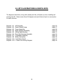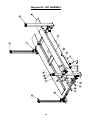
1
9,000 lb. (4091 kg) Closed Front 4-Post Lifts LSS4P9PLXLAL – Quatro-Stacker XL 8,000 lb. (3636 kg) Closed Front 4-Post Lifts LSS4P8PLDXAL – Quatro-Stacker (Minimum wheel base 110’’ at rated capacity) READ the Manual Thoroughly Before Installing, Operating, Servicing, or Maintaining the Lift SAVE this MANUAL and ALL INSTRUCTIONS Lift Superstore Issue 03 2300 Speers Rd. Oakville, Ontario L6L 2X8 Phone: (866) 766-‐5438 Fax: (905) 891-‐1214 www.liftsuperstore.com 1 Effective: Aug. 12 , 2014 Your new lift will provide years of dependable service if installed, operated and maintained properly. Follow all safety, installation, operation, and maintenance instructions in this manual before installing and operating the lift. In addition, follow all safety and other information included on and with the lift before operating the lift. Keep this manual in a secure place for future reference, training and service part identification. TABLE of CONTENTS 1. Unloading Procedure & Lift Package Contents page 3 2. Warranty & Safety page 4 3. General Requirements & Lift Specifications page 7 4. Tools Required & Pre Installation Procedures page 8 5. Installation Procedures page 10 6. Operating Instructions & Lift Maintenance page 15 7. Troubleshooting page 21 8. Lift Installation Diagrams & Parts Lists page 24 It is the shop owner's responsibility to provide a satisfactory installation area for the lift. Lift should only be installed on level concrete floors with no more than 3º of slope and with a minimum of 4 inches (102mm) and 3000 psi (20.7MPa) concrete that has been aged a minimum of 30 days. Please consult a qualified individual if any doubt exists concerning proper installation and subsequent safe operation of the lift. Do not install the lift on asphalt or outdoors. Failure to comply with these minimum standards could result in personal injury or death. Prior to installation, it is the shop owner's responsibility to provide constant electrical power in the correct voltage, phase, etc., and all wiring for electrical hook-up of the lift. The shop owner must insure that the electrical installation conforms to local building and safety codes. Where required, the shop owner will provide an electrical isolation switch located in close proximity to the lift. This switch will have an emergency stop capability and isolate electrical power from the lift for servicing requirements. It is the shop owner's responsibility to provide necessary lockout/tagout means for energy sources per ANSI Z244.1-1982 (R1993), Safety Requirements for the Lockout/Tagout of Energy Sources, before beginning any lift repairs. Hydraulic oil will be supplied by either the shop owner or the installer. ISO 32 hydraulic oil (10W non detergent) must be used to fill the reservoir tank before operating the lift. It is the shop owner's responsibility to train all operators in lift operation and lift safety. 2 1. UNLOADING PROCEDURE & LIFT PACKAGE CONTENTS For your information: All lift components are packaged together in one module held together by steel frames Optional accessories (rolling jacks and turnplates) are packaged separately. UNPACKING PROCEDURE: When the lift arrives on site: 1. If possible have lift unloaded in the installation area and on two 4"x 4" x 24" Wooden Blocks (required for unpacking). 2. Check for freight damage and report immediately to the trucking company who delivered the lift. 3. Check for missing parts and report immediately to the factory 1-877-799-LIFT(5438) or (289) 291-3335 Main Components include: Columns – 4 pc Runway Assemblies – 2 pc Crossmembers – 2 pc (1 front – 1 rear) Powerpack – 1 pc Accessories (see list below) Accessory includes: Lifting Cables - 4 Hydraulic Hose – 1 pc Approach Ramps – 2pc Wheel Stops - 2 WL 200 Series Safety Information Label Kit ALI - “Lifting It Right “ Manual Automotive Lift Safety Tips Hang Card Automotive Lift, Operation, Inspection and Maintenance Manual Owner’s Manual Hardware Box includes: Fittings, bolts, washers, nuts, shims, and anchor bolts, etc. 3 2. WARRANTY & SAFETY Warranty: The four post lift models identified in this manual have the following warranty from date of purchase: Structural Components - 5 year Hydraulic and Other Components - 2 year The above items are warranted to be free of defects in material and workmanship to the original owner of the lift as follows: This warranty does not extend to defects caused by ordinary wear, misuse, abuse, improper maintenance, shipping damage or where repairs have been attempted or made by anyone other than the manufacturer or a manufacturer certified technician. This warranty is exclusive and in lieu of all other warranties express or implied. In no event shall the manufacturer be liable for special, incidental or consequential damages for any breach or delay in performance of the warranty. The manufacturer reserves the right to change specifications, designs or add improvements to its product line without incurring any obligation to make such changes to products sold previously. IMPORTANT SAFETY INSTRUCTIONS When using your garage equipment, basic safety precautions should always be followed, including the following: 1. Read all instructions 2. Care must be taken as burns can result from touching hot parts 3. Do not operate equipment with a damaged cord or if equipment has been dropped or damaged – until it has been examined by a qualified service person 4. Do not let a cord hang over the edge of the table, bench, or counter or come in contact with hot manifolds or moving fan blades 5. Let equipment cool completely before putting away. Loop cord loosely around equipment when storing 6. To reduce risk of fire, do not operate equipment in the vicinity of open containers of flammable liquids (gasoline) 7. Adequate ventilation should be provided when working on operating internal combustion engines 8. Keep hair, loose clothing, fingers, and all parts of body away from moving parts 9. To reduce the risk of electric shock, do not use on wet surfaces or expose to rain 10. Use only as directed in this manual. Use only manufacturer’s recommended attachments 11. ALWAYS WEAR SAFETY GLASSES. Everyday eyeglasses only have impact resistant lenses, they are not safety glasses SAVE THESE INSTRUCTIONS 4 Basic common sense safety precautions should always be followed when installing, operating and maintaining the lift as a risk of fire, electric shock, injury or death may be present. In addition: 1. Read and follow all safety instructions and decals included with the lift. Read and follow all safety instructions in this manual. Read and follow the ALI "Lifting It Right" manual (included with the lift). Always use the "Vehicle Lifting Points" reference guide when lifting a vehicle. Insure all materials stay up to date »» www.autolift.org/ 2. Only trained and authorized personnel should position a vehicle and operate the lift. 3. Inspect the lift daily. Do not operate if potential problems have been identified or lift malfunctions. Do not operate if lift has damaged or broken components. Never walk or work under the lift unless all safety locks are completely engaged. 4. Never overload the lift. The hydraulic system on this lift is not designed to be a load holding device. Mechanical safety locks must be engaged before proceeding under the lift for vehicle servicing or lift maintenance. Never override operating controls. This is unsafe and will void the warranty. 5. Before driving a vehicle onto the lift, insure that the lift and lift area is clear of all debris and that all oil and grease has been cleaned from runway surfaces. 6. Always chock wheels and set parking brake before lifting vehicle. 7. When using a jack(s) to raise a vehicle, position jack lifting pads to contact vehicle manufacturers recommended lifting points. Raise jack slowly until all pads contact the vehicle. Confirm that the vehicle is stable on the jack(s) before raising to desired working height. 8. Important: Removal or installation of heavier parts can change the vehicle's center of gravity on the jack(s) resulting in a critical load shift. The vehicle may then be unstable. Plan ahead for this possibility to insure continued safety and refer to the vehicle manufacturer’s service manual for recommended procedures. 9. Always keep the lift area free of obstructions and debris. Grease and oil spills should be cleaned up immediately. 10. Never raise a vehicle on the lift with passengers inside. Before lowering, check the lift and lift area and remove all obstructions. Before removing vehicle from the lift or lift area, confirm an unobstructed exit. 11. DO NOT PERFORM ANY MAINTENANCE OR INSTALLATION OF ANY COMPONENTS WITH OUT FIRST ENSURING THAT ELECTRICAL POWER HAS BEEN DISCONNECTED AT THE SOURCE OR PANEL AND CANNOT BE RE-ENERGIZED UNTIL ALL MAINTENANCE AND/OR INSTALLATION PROCEDURES ARE COMPLETED (ANSI 244.1). 5 Safety Instruction and Information Decal Kit (included with the lift) Review all safety information daily with all lift operators IMPORTANT : Insure Safety Instruction Decals and Hang Card are affixed to the lift immediately following installation and before the lift is used LIFT SAFETY AND LIFT MAINTENANCE MUST BE PART OF YOUR DAILY ROUTINE 6 3. GENERAL REQUIREMENTS & LIFT SPECIFICATIONS 9,000 lb. (4091 kg) Capacity - 4,500 lbs. (2045.5 kg) each Runway 8,000 lb. (3636 kg) Capacity - 4,000 lbs. (1818 kg) each Runway A constant supply of 230V 1PH 60Hz 30A electrical power is required for this lift. Ongoing design modifications and quality improvements may change specifications listed in this manual without notice 7 4. TOOLS REQUIRED & PRE INSTALLATION PROCEDURES TOOLS REQUIRED ü ü ü ü ü ü ü 30ft. measuring tape, chalk line and chalk, 2 x 4 ft. level (laser level also suggested) Wooden blocks, Step Ladder Work stands - 4 (runway set-up and installation) Metric and SAE wrenches sets, ratchet sets and Allen key sets Crow bar, hammer and screwdrivers Rotary hammer drill c/w ¾ inch diameter masonry drill bit 3 Gallon of Hydraulic Oil (ISO 32) PRE-INSTALLATION PROCEDURE Before proceeding with installation, read the installation manual and insure all instructions are fully understood and all component parts listed on page 3 are accounted for. Identify bay center line near the front and mark the floor. Also mark center of the bay entrance. Connect these two points with a chalk line "A". Refer to diagram on the next page for minimum clearance from bay entrance door and draw a second chalk line "C" at 90° to the centerline “A”. Measure 175.4’’ (8000lb lift) or 190.6’’ (9000lb lift) from line “C” and mark front baseplate line “B”. Make sure “B” is perpendicular to “A” and has enough (24’’) clearance to the front obstacles, e.g. wall and any other equipment. Refer to diagram and draw line “D” and “E” symmetrically to “A”. Distance between “D” and “E” is 103.6’’ (8000lb lift) or 109.5’’ (9000lb lift). “D” and “E” shall both perpendicular to “B” and ”C”. Line “B”, “C”, “D” and “E” are baseplate outlines. These locations will be used to initially position each column, however, the 4 most critical measurements will be inside column to inside column measurements confirmed later in the installation process. Confirm that the column baseplate locations you have marked are a minimum distance of 6 inches from any floor seam. Do not install if floor has cracks or deterioration that could affect lift stability. The shop/lift owner is responsible for confirming there are no obstructions in the installation area like floor drains, under floor piping or electrical conduit that could be damaged or prevent safe lift installation and secure lift anchoring. Check ceiling for beams or heating ducts and walls for protruding structures, etc. (overhead clearance must be the height of both vehicles added together plus 8’’). Insure that the lift can be safely installed in the position you have marked out on the bay floor. INSTALLATION NOTE: Installation Step #20/#21 require at least 60” of clearance to allow the installer to insert the required linkages. If room does not permit, the lift should be assembled in a temporary position, and using the wheel dollies provided with the lift, moved into final position after Step #21 8 9 5. INSTALLATION PROCEDURE Insure the lift installation complies with ANSI/ALI/ALIS, Safety Requirements for installation and Service of Automotive Lifts. 1. Remove protective wrapping from the lift and clear installation area of packaging materials. Place two wooden blocks under the lift to enable fork lift or other access and to allow for removal of shipping frames. Unbolt steel shipping frames and remove from installation area. Take adequate precautions when working with runways, columns and other components. 2. Find the end of the hose that is mounted to the cylinder and tighten the elbow that attaches the hose to the side of the runway using the nut. Check the fitting at the cylinder bottom and make sure it is tight. 3. Pull or push the plate on the end of the cylinder to make the cylinder rod out of the cylinder by about 40’’. Make sure that the 1/2’’ plate is threaded tight against the cylinder rod. Also, be sure that the 1/4’’ plate is on the rod and hand tighten the lock nut on the rod. 4. Unbolt the top runway (with cylinder underneath) from the shipping frame. Secure runway with a hoist if necessary. Place the runway in the bay with the hydraulic fitting facing toward the outside. Ensure the hydraulic fitting is near the power side column position. 5. Unbolt the four Vertical Columns from the shipping frame and place the column with the power unit mounting bracket at the far left corner from the bay entrance. Stand these Vertical Columns on their base plate by following the pre installation diagram (pg. 8). Ensure each Vertical Column Top Plate has the longer side, with the hole, oriented towards the inside of the lift layout ( see Diagram#8) 6. Unpack the bottom runway (no cylinder). Place the two crossbeam at each end of the lift with the pulley facing inside. Remove the shipping brackets from the bottom runway and turn over placing the runway in the bay next to the other runway with the “L” shaped edges facing each other. 7. Remove the top plates, and slide each crossbeam into the front or rear two columns. 8. Unpack the Lock Ladders from the package and slide them into the precut slot on the slider (item # 15, diagram #7) inside each column. After removing the top nut from the lock ladder and now you are ready to install the top plates on to the columns (see diagram #3). 9. Secure top cap and lock ladder assemblies together with washer and nut. Position the crossbeams at the third lowest locking position on all columns. 10 10. Square the lift by following pre installation diagram. Confirm the baseplates distances. Measure diagonal distance between front driver side column and rear passenger side. Compare this distance to the other baseplates diagonal distance. This should be within 1/2’’ to allow some forgiveness to bolt on runways. 11. Lift the runways onto the cross beam and bolt them in place using the 20mm holes towards the outside of the crossbeams. The four drop-in ramp plates will be used with the spacer side facing the lift and through bolted from the outside of the cross rail, through the runway using M18 bolts provided with washers, lock washers and nuts. 12. Cable installation: Lay out all cables and measure from end to end and compare with diagram #5 for the correct cable positions. 13. Route the cables by starting with the pulley at the end of the crossbeam and work way back to the cylinder. Ensure the cable runs inside the small upper pulley in the crossbeam. (see diagram below for cable lock pulley relative position to cable). 14. Secure each of the four cables in the wire rope anchor located at the shaft end of the hydraulic cylinder. 15. Run the threaded cable ends into the holes in the top plates of the columns and secure with washers and nuts. At this stage only hand-tighten as final adjustments will be needed. Tighten the nylock nut on the end of the cylinder at this time. 16. Hydraulic assembly - Refer diagram #1, locate 5/16’’ Bolt and Washers (item 25 and 27), and mount the power unit on the mounting bracket on the power-side column. 17. Refer diagram #1, attach the elbow fitting on the power unit’s P-port. Do not over tighten. Install the hose (item 17) to the fitting on the side of the runway and connect opposite end to the elbow fitting on the power unit. 18. Safety release assembly – The single point safety lock release assembly is a system of connecting rods and linkage that disengage the four lock latches. Refer Diagram #4 and locate the required items. 11 19. Slip spacer (item 3 in diagram #4) over threaded end of handle rod (item 6 in diagram #4) and insert rod into hole on crossbeam near power column. 20. Slip another spacer over threaded end of T-rod (item 9 in diagram #4) and insert end into hole located on the rear crossbeam. Run rod through rod guides located under the deck. 21. Locate connecting rod (item 10 in diagram #4) and the two connectors (item 1 in diagram #4). Install the rod in between by flowing diagram #4. Make sure the rod is in rod guides under the deck. Adjust connectors to take the slack out of the rods. The rods should remain free enough to move with no slack. Do not tighten connectors or lock nuts at this time. 22. Locate the two long rods (item 5 in diagram #4) and remove one end from each rod and slide off the eye bolt (item 4 in diagram #1). Install the eye bolt on the middle of each crossbeam with the M10 nuts. 23. Attach short rods (item 7 in diagram #4) on the T shape lock on the bottom of the T and hand tighten. Slide long rod through the eye bolt and attach on end to the top side of the T. Install the other sides of the rods on each safety lock lever (see item 8 in diagram #7). Do the same on the other crossbeam. Before tightening, ensure each of the T-rods are oriented in a vertical manner. Tighten all jam nuts. 24. Tighten the jam nuts on the handle rod and the T rod. 25. Finally, adjust and tighten the rod connectors under the deck, and tighten the jam nuts against the connectors. 26. Fill oil tank with three gallons of ISO32 hydraulic oil. Install breather (black) on top of of the oil tank, and put cap (red) on the bottom of tank (DO NOT DRILL OIL TANK). 27. Final adjustments: Check all cables and make sure they are all in their pulleys. Press up button on the power Unit and let fluid pump into the cylinder. Once the lift is raised off the locks, release the up button and pull the safety lock release handle to disengage all locks and then lower the lift with the lowering lever on the power unit (locks must be disengaged while lowering). Keep holding decent lever for seconds after the lift reaches its bottom position to let air escape. 28. Raise the lift up by about 10’’. Measure the height of the crossbeam at each column to determine the highest point. Adjust the cable on the highest point column until at least 3 threads pass through the nylock nut. Then adjust the other three cables to match this height to ensure the runways are level. 29. Raise the lift until you hear each column lock “click” into position. Using the down lever only, allow the runways to sit into the locks. Measure each corner of the runways and adjust the lock ladder accordingly to ensure level. 30. Operate the lift with a vehicle. Raise and lower the lift three times. Confirm all the operational functions, equalizing cables and safety lock work well. 12 NOTE: This lift does not require bolting to the floor, but if you choose the option to anchor the lift to the floor please follow the detailed instructions and criteria below. FOUNDATION and ANCHORING REQUIREMENTS: Lift should only be installed on level concrete floors with no more than 3º of slope and a minimum of 4 inches (102mm) and 3000 psi (20.7MPa) concrete that has been aged a minimum of 30 days. A qualified person should be consulted to address seismic loads and other local requirements. Do not install the lift on asphalt or outdoors. Maintain a 6’’ minimum distance from any slab edge or seam. Hole depth should be a minimum of 4’’. When use shims, MAKE SURE shim thickness not exceed 1/2’’ when using the anchors with the lift. 13 14 6. Operating Instructions & Lift Maintenance Insure this manual along with all operation, inspection and maintenance instructions are delivered to the owner/user/employer LIFT OPERATION: Before lifting a vehicle, insure all operators are qualified, have been trained and are following all safety instructions. Read and follow the ALI "Lifting It Right" manual included with the lift. Always use the "Vehicle Lifting Points" reference guide when lifting a vehicle. Insure all materials stay up to date »» www.autolift.org/ (see example of SAE J2184 standard below) Insure that every vehicle will be securely positioned on the lift. When using air/hydraulic rolling jacks, always use vehicle manufacturer's recommended lifting points (see picture below). Never allow anyone under the lift when raising or lowering. Always insure mechanical safety locks are completely engaged on all four columns before proceeding under the lift or a vehicle. Controls on the powerpack and crossbeam perform the following functions: Push button on power unit: raises the lift. Safety Release Handle: retracts or releases safety locks at all four columns. This handle (along with the "DOWN HANDLE") must be pressed and held during the entire lowering procedure. Down handle on power unit: lowers the lift. Note: Before lowering the lift you should raise it slightly to remove pressure from safety locks allowing them to disengage completely. 15 PRE-OPERATION CHECK LIST Trained Lift Operator ü All lift operators must be fully trained and qualified to safely and effectively operate the lift described and covered in this manual. Absence of All Obstructions ü The total work area must be free of any and all obstructions and be generally clean of oil and debris. Visual Inspections ü Every lift operator must thoroughly inspect the lift noting any problem area. An inspection of the floor area and anchor bolts must also be completed. Report any questionable item. "No Load" Performance Check ü ü ü ü ü ü ü All mechanical safety locks are operating properly and consistently No External Fluid Leaks No Lift "Bleed Down". Effortless and Simultaneous Movement Level Lifting All Controls Function Properly Safety Mechanisms all functional Previous Operator's Report ü Verify with previous operator and/or supervisor that there is no problem with the lift. If any problem has been reported, insure all necessary repairs have been completed. 16 LIFT OPERATION with a TYPICAL VEHICLE Lift Operation ü Perform pre-operation check list item by item ü Ensure lift is completely lowered ü Position vehicle on the lift Caution ü Avoid sudden "starts and stops" during loading and unloading of vehicle To Load a Typical Vehicle ü Position vehicle on the lift runways by using the approaching ramp. Make sure the center of gravity is located evenly between the columns. The individual axle weight should not exceed 50% of the lift capacity. ü Set vehicle parking brake and chock tires. ü Make sure vehicle is neither front nor rear heavy. To Raise the Lift ü Insert runway stops before raising the lift. ü Push up button to raise the lift by about 10’’. ü Check for the vehicle movement and weight distribution. Raise to desired height if secure. ü Press "DOWN" handle to lower lift on to the mechanical safeties. ü DO NOT WORK UNDER A LIFT THAT IS NOT IN THE LOCK POSITION. To Lower the Lift ü Inspect the lifting area to insure all personnel and debris have been cleared away. ü Raise the lift slightly and disengage all safety locks by pulling the safety release handle. ü Press the lowering lever on the power unit to begin lowering. Safety locks must be all disengaged during the lowering. ü Lower lift completely to the floor. Remove runway stops, carefully drive off the vehicle from the lift runways. 17 MAINTENANCE INSTRUCTIONS Maintenance is to be performed by factory trained lift service personnel only. Important: Regularly inspect the hydraulic pressure developed upon the rated capacity, and make sure the pressure doesn’t exceed the operating pressure (2000 psi for 9000lb lift and 1800 psi for 8000lb lift). The following is a minimum maintenance schedule: DAILY: üRaise and lower the lift (with no vehicle) at the beginning of each shift to verify the runways are level, safety locks are engaging, and the lift is operating properly. üCheck all hydraulic fittings and lines for damage and leaks. Check electrical wiring for damage. üCheck all moving parts for uneven or excessive wear. Repair or replace all damaged, worn, or broken components immediately. üClean all debris from the base frame area üRemove oil/grease on runways and rolling jack lift pads. WEEKLY: üCheck hydraulic fluid in reservoir and top up if required. üCheck cables, cable pulleys and lifting cylinder. MONTHLY: üCheck that all anchor bolts are torqued to minimum 75 ft-lbs (102Nm). üClean and lubricate moving parts. EVERY YEAR: üHave a certified lift technician inspect and certify all aspects of the lift. EVERY TWO YEARS: üChange and replace hydraulic oil in cylinders and powerpack reservoir. LUBRICATION: üRefer diagram #10 for lubrication points. üWhere grease is required use a multi-purpose lithium grease. üWhere lubricating oil is required use a SAE 30 oil. üWhere hydraulic oil is required use ISO 32 hydraulic oil (10W non detergent ). 18 The following criteria will determine when a lifting cable is no longer acceptable for service: • 12 randomly distributed broken wires in one lay or four broken wires in one strand in one lay in running ropes • one outer wire broken at the contact point with the core of the rope, which has worked its way out of the rope structure and protrudes or loops out from the rope structure • wear of one-third the original diameter of outside individual wires • kinking, crushing, bird caging, or any other damage resulting in distortion of the rope structure • evidence of heat damage from any cause • reduction from nominal diameter greater than those listed in the following table: Rope Diameter (inch) Max. allowable reduction (inch) Less than or equal to 5/16’’ 1/64’’ More than 5/16‘’to 1/2’’ 1/32’’ More than 1/2’’ to 3/4’’ 3/64’’ If any of the cable is as shown in the following pictures, do not use. 19 Note: Attention shall be given to end connections. Upon development of two broken wires adjacent to socket end connections, the rope shall be resocketed or replaced. Resocketing shall not be attempted if the resulting rope length will be insufficient for proper operation. CABLE ADUSTMENT Initial adjustment Adjust cable with lift fully lowered. Loosen jam nut and tighten nut on cable stud on top of column until crossbeam end is raised 1/4’’ and back off nut one turn. Retighten jam nut. Repeat for all four cables. Final adjustment 1. Load a typical vehicle on lift. 2. Raise lift to full height and then lower lift onto top latch position. 3. Starting with the right front column, use a straight edge to mark the position of the crossbeam bottom on the column. 4. Raise lift to full height again and mark second position. If gap between two marks is less than 2’’, adjust locking latch bar to reach clearance of 2’’. Repeat for the other three columns. 5. Adjust locking latch bar by adjusting nut so that the bottom of the top-most locking slot is at least 2’’ below locking latch. After adjustment, tighten jam nut underneath column top plate. 6. If the entire 2’’ clearance cannot be attained by adjusting the locking latch bar, adjust the cable. Turn cable adjusting nut to raise the locking latch 2’’ above bottom of latch bar slot. Then tighten cable jam nut. 7. Lower lift and remove vehicle. Raise the lift to full height. Listen and watch as the first locking latch clicks into place. Synchronize the other three columns with this column by adjusting their cables so all four latches click at the same time. Tighten jam nuts. When adjusting cables, always leave at least 1/4’’ showing between nut and stud end. Latches may not click in at the same time when vehicle is being raised. They should be close. Be sure all four corners have passed the locking latch bar slot before lowering lift on locking latches. 20 7. TROUBLESHOOTING The following are suggestions to consider if you have problems with the lift. Please call a qualified lift technician and/or a qualified electrician for further clarification and information. Problem Lift Will Not Raise or Lower 1. 2. 3. 4. 5. 6. Possible Causes Blown fuse or circuit breaker Tripped thermal overload Incorrect voltage to motor Bad wiring connections "UP" switch burned out Motor windings burned out 1. 2. 3. 4. 5. 6. Lift Will Not Raise 1. 2. 3. 4. 5. 6. 7. 8. Air in oil or low oil level Lowering Valve leaks Motor runs backward Pump damaged Pump will not prime Relief Valve leaks Voltage to motor incorrect Lift overloaded 1. 2. 3. 4. 5. 6. 7. 8. Lift Will Not Lower 1. Mechanical locks are engaged 2. Obstruction under lift or in glide block tracks 1. Raise unit slightly and disengage mechanical locks 2. Carefully remove obstruction - clean glide block tracks Lift Will Not Hold Pressure 1. 2. 3. 4. 5. Lift Will Not Raise A Vehicle 1. Low hydraulic fluid 2. Malfunction of pressure relief valve 3. Insufficient electrical voltage 4. Lift overload 5. Motor is running backwards 6. Air in hydraulic oil 7. Pump will not prime 8. Pump is damaged 9. Faulty lowering valve 1. Check oil level - bleed cylinders - remove contamination - replace oil seal 2. Check fitting, replace cylinder 3. Contaminated fluid, handle binds, clean valves 4. Clean check valve (replace if necessary) 5. Check all fittings and repair leaks 1. Lower lift. Using ISO grade 32 hydraulic oil, fill the powerpack reservoir to 1" below the top 2. Clean pressure relief valve. if problem continues, call a service technician 3. Confirm a 208/230 volt power supply to the lift 4. Check that vehicle weight is evenly distributed and does not exceed rated capacity. 5. Confirm proper motor rotation - rewire if required 6. Check oil seal and bleed hydraulic system 7. Check hydraulic oil level and pick-up tube. Replace pump if required 8. Repair or replace pump 9. Clean or replace valve Contamination in system Internal Cylinder leaks Lowering Valve leaks Check Valve leaks External leaks 21 Solution Replace fuse or reset/replace circuit breaker Reset thermal overload Supply correct voltage to motor Repair and insulate all connections Replace switch Replace motor Check fluid level, oil seal, bleed system Clean valve or replace Check for correct wiring Repair of replace pump Check fluid level and pick-up tube - replace pump Clean Relief Valve (replace if necessary) Supply correct voltage to motor Verify that loaded vehicle weight does not exceed rated lift capacity Problem Slow Drift Down Possible Causes 1. Mechanical safety locks not engaged 2. Powerpack lowering valve contamination 3. Hydraulic system leaks Solutions 1. Raise lift to engage all safety locks then lower lift and confirm all safety locks are engaged 2. Back flush powerpack by opening manual overright valve. Engage "up" switch and down lever at the same time and run approximately 10 seconds 3. Check cylinder and all fittings for any hydraulic oil leak Lift Going Up Out of Level 1. Lift installed on un-level floor 2. Cable(s) out of adjustment 1. Reinstall on level surface 2. re-adjust cables - Call service technician if problem persists Anchors Will Not Stay Tight 1. Holes drilled oversize 2. Concrete floor thickness or holding strength not sufficient 1. Relocate lift using the correct bit to drill holes 2. Break out old concrete and re-pour new foundation per lift installation instruction Call factory for technical assistance if lift becomes inoperative in the raised position, and the maximum operating hydraulic pressure developed upon lifting the rated capacity. Replace all worn or broken parts and components only with manufacturer approved/supplied parts and components Replacement parts may be purchased from your local lift supplier or the manufacturer at: 1-877-799-LIFT(5438) or (289) 291-3335 22 9,000 lb. (4091 kg) Closed Front 4-Post Lifts LSS4P9PLXLAL – Quatro-StackerXL 8,000 lb. (3636 kg) Closed Front 4-Post Lifts LSS4P8PLDX – Quatro-Stacker for installation & service part reference SAVE this MANUAL and ALL INSTRUCTIONS Lift Superstore Issue 03 2300 Speers Rd. Oakville, Ontario L6L 2X8 Phone: (866) 799-‐5438 Fax: (905) 891-‐1214 www.Liftsuperstore.com 23 Effective: Aug. 12, 2014 8. LIFT ILLUSTRATIONS & PARTS LISTS The diagrams listed below, along with related parts lists, will assist you when installing and servicing this lift. Please ensure these lift diagrams and parts lists are kept in a secure place for quick reference. Diagram Diagram Diagram Diagram Diagram Diagram Diagram Diagram Diagram Diagram #1 - Lift Assembly #2 - Caster Wheel Frame #3 - Tower Assembly #4 - Safety Release Assembly #5 - Lifting Cable Routing #6 - Diver Side Runway Assembly #7 – Crossbeam Assembly #8 - Safety Instruction #9 – Lubrication Points #10 – Power Unit Wiring Diagram 24 page page page page page page page page page page 25 27 28 29 31 32 34 36 37 38 Diagram #1: LIFT ASSEMBLY 25 ITEM NO. 1 2 3 4 PART NUMBER 44090005/44080005* 44090002/44080002* 24090012 14090074 5 44090001/44080001* 6 7 8 9 10 14090063 24090015/24080015* 44090003/44080003* 24090007/24080007* 34090009 11 12 13 34090007 HYDRAULIC HOSE 44090010/44080010* SAFETY RELEASE ASSEMBLY 34090011 CYLINDER ELBOW FITTING TOWER ASSEMBLY (REAR PASSENGER 44090009/44080009* SIDE) 44090004/44080004* FRONT CROSSBEAM ASSEMBLY 34090010 POWER PACK 34090008 HYDRAULIC HOSE 24090013 WHEEL STOP HOLDING PLATE 3C000172 M18X100 HEX BOLT 3C000101 20MM PLAIN WASHER 3C000173 18MM SPRING LOCK 3C000174 M18 NUT 3C000100 3/4 UNF NUT 3C000104 M10 NUT 3C000143 5/16’’ FLAT WASHER 3C000000 5/16’’ SPRING LOCK WASHER 3C000001 5/16’’ HEX BOLT 3C000145 5/16’’ HEX BOLT 14 15 16 17 18 19 20 21 22 23 24 25 26 27 28 DESCRIPTION REAR CROSSBEAM ASSEMBLY TOWER ASSEMBLY (POWER SIDE) RAMP SAFETY RELEASE BAR HOOK TOWER ASSEMBLY (FRONT PASSENGER SIDE & REAR DRIVER SIDE) WHEEL STOP JACK TRAY DRIVER SIDE DECK PASSENGER SIDE DECK HYDRAULIC ELBOW FITTING *: 8000lb LIFT 26 QTY. 1 1 2 2 2 4 1 1 1 2 1 1 1 1 1 1 1 4 8 12 8 8 4 3 8 4 4 4 Diagram #2: CASTER WHEEL FRAME ITEM NO. PART NUMBER DESCRIPTION QTY. 1 2 3 4 5 6 7 8 24090014 34090005 44090077 3C000076 3C000156 3C000067 3C000104 3C000168 WHEEL BRACKET WELD. WHEEL ASSEMBLY WHEEL SUPPORT SHAFT 10MM PLAIN WASHER M12X35 BOLT 10MM SPRING LOCK WASHER M10 NUT 4X50MM SPLIT PIN 4 4 4 32 16 16 16 4 27 Diagram #3: Tower Assembly FRONT DRIVER SIDE: ITEM NO. PART NUMBER 1 24090005/24080005* 2 24090001/24080001* 3 24090003 4 3C000054 5 3C000101 6 3C000156 7 3C000055 8 3C000157 9 3C000100 REAR DRIVER SIDE: DESCRIPTION QTY. SAFETY LADDER WELDMENT TOWER POWER SIDE WELD. TOP PLATE WELDMENT A 12mm PLAIN WASHER 20mm PLAIN WASHER M12X35 BOLT 12mm SPRING LOCK WASHER M12 NUT M20 NUT 4 1 2 32 4 16 16 16 8 ITEM NO. PART NUMBER DESCRIPTION 2 24090002/24080002* TOWER NON POWERSIDE WELD. FRONT PASSENGER SIDE & REAR DRIVER SIDE: ITEM NO. PART NUMBER 3 24090004 *: 8000lb LIFT DESCRIPTION TOP PLATE WELDMENT B 28 QTY. 3 QTY. 2 Diagram #4: Safety Release Assembly 29 ITEM NO. 1 2 3 4 5 6 7 8 9 10 11 12 13 14 *: 8000lb PART NUMBER 14090078 34090006 14090081 14090085 14090083/14080083* 44090008 14090084 14090086 24090016 14090077/14080077* 3C000169 3C000169 3C000169 3C000175 LIFT DESCRIPTION QTY. CONNECTOR LEVER JOINT SI6TK M6 COVER PIPE LEVER BUSHING SAFETY RELEASE BAR SAFETY RELEASE BAR W/ LEVER SAFETY RELEASE BAR PLASTIC HANDLE BALL SAFETY RELEASE BAR WELD. SAFETY RELEASE BAR 6MM WASHER M6X35 HEX BOLT M6 NYLON NUT M6 NUT 2 8 2 4 2 1 2 1 1 1 4 4 4 8 30 Diagram #5: Lifting Cable Routing ITEM NO. PART NUMBER 1 34091001/34081001* 2 34091002/34081002* 3 34091003/34081003* 4 34091004/34081004* *: 8000lb LIFT CABLE LENGTH 289’’/266.5’’* 351’’/323’’* 115’’/107’’* 176.5’’/161.5’’* 31 QTY 1 1 1 1 Diagram #6: Driver (left) Side Runway Assembly 32 ITEM PART NUMBER NO. 1 24090006/24080006* 2 14090087 3 14090088 4 14090089 5 14090090 6 14090092 7 14090049 8 44090011/44080011* 9 14090091 10 3C000159 11 3C000163 12 3C000160 13 3C000161 14 3C000162 15 44090012 *: 8000lb LIFT DESCRIPTION QTY. MAIN DECK WELDMENT PULLEY SPACER(SHORT) PULLEY SPACER(LONG) CYLINDER FIX PIN CABLE PLATE PULLEY SHAFT SHAFT CLIP CYLINDER CABLE PLATE(THICK) M6X12 SCREW 6MM SPRING LOCK WASHER SPLIT PIN CYLINDER NYLOCK NUT 24MM PLAIN WASHER PULLEY W/ BUSHING 1 2 2 1 1 4 4 1 1 8 8 2 1 1 10 33 Diagram #7: Crossbeam Assembly 34 ITEM NO. 1 2 3 4 5 6 PART NUMBER 14090045 14090056 14090042 14090048 24090010 24090011 7 24090009 8 9 10 11 14090053 14090054 14090057 14090043 DESCRIPTION QTY. LOCK SHAFT 4 SAFETY LOCK SPACER 4 COVER A 2 SAFETY LOCK 4 SPINDLE 4 LOCKING BLOCK B 2 LOCKING BLOCK A (NOT SHOWN, ON THE 2 OTHER SIDE) SAFETY RELEASE LEVER 4 BOSS 4 TORSION SPRING B 2 COVER B 2 12 13 14 15 16 17 18 19 20 21 22 23 24 25 26 27 28 29 30 14090046 14090058 14090059 14090044 14090047 24090008/24080008* 14090049 44090012 3C000101 3C000162 3C000107 3C000164 3C000166 3C000167 3C000163 3C000061 3C000111 3C000159 3C000165 PULLEY SHAFT TORSION SPRING A (ON THE OPP. SIDE) SPRING SLIDER CABLE SAFETY WHEEL CROSSBEAM WELDMENT SHAFT CLIP PULLEY W/ BUSHING 20MM PLAIN WASHER 24MM PLAIN WASHER 6MM PLAIN WASHER 8MM PLAIN WASHER M8X12 SET SCREW 8MM LOCK WASHER 6MM SPRING LOCK WASHER M8 NUT M6X10 SCREW M6X12 SCREW M8X35 SOCKET BOLT *: 8000lb LIFT 35 4 2 4 4 4 2 4 10 8 12 4 32 4 8 8 8 4 8 32 Diagram #8: SAFETY INSTRUCTIONS 36 Diagram #9: Lubrication Points 37 Diagram #10: Power Unit Wiring Diagram 38