1
STM Electronics Corporation
Authorized Dealer
Manual
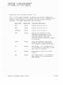
DEALER MANUAL
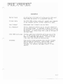
Subject
Section
11
PIED PIPER
11 1
Peripherals
IV
Expansion
V
WarrantyjService
VI
Pricing
V11
Hardware Information
VIII
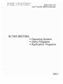
Software Information
IX
User's Manual
Х
AdvertisingjPromotion
XI
Ое а 1er
INDEX
Information
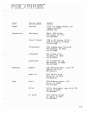
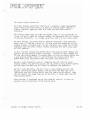
SECTION 11:
PIED PIPER
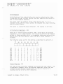
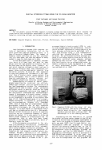
The PIED PIPER ропаЫе microcomputer with integral1 МЬ drive
а
The P1ED P1PER introduces
new breed of low cost, high performance
computers for both beginners and advanced users who demand that their
system expand with their requirements.
The P1ED P1PER is the least
expensive, truly portable, fully featured, expandable computer with
integral disk drive.
1t is compatible with both video monitors and
televisions.
Designed so both the beginner and sophisticated user will find it
pleasure to operate, the P1ED P1PER offers
hardware and software at
ТНЕ
а
ап
а
excellent combination of
surprisingly low price.
FULLY FEATURED P1ED P1PER 1NCLUDES:
P1ED PIPER with built-in floppy disk.
СР/М
2.2 operating system and utilities.
PIED PIPER utilities.
The Perfect Software package of word processing, spelling
checker, spreadsheet, and filer programs.
lnstruction manuals for the system and application programs.
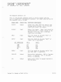
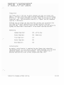
11.2
HARDWARE
Processor
Memory
FEATURES
Z80A microprocessor / 4Mhz
64К
4К
2К
2К
bytes of RAM
bytes of read оп1у memory
bytes of video disp1ay
buffer.
bytes of read оп 1у memory
for character generation.
BENEF lТS
The Z80A provides access to ап
enormous library of existing
programs and the 4Mhz (speed)
a110ws the programs to run in
approximate1y half the time of
conventiona1 micro computers.
The PIED PIPER uses а ful1 64К
of RAM. p1us, Ьу using other
memories, it a110ws as much
user space as possib1e.
Keyboard
Ful1 size, ASC11 typewritersty1e keyboard; 61 keys.
With this typewriter sty1e keyboard, there is по need to
relearn key locations.
Printer
Centronics type para11el
printer port.
Accepts апу of the 1etter quality
and/or dot matrix printers which
use а standard paralle1 port
connector.
Disp1ay
Capabi1ity
24 lines of 80 characters
for video monitor.
24 lines of 40 characters
for TV with horizonta1
scro11ing feature to view
80 со 1umns.
Upper/lower case p1us
character graphics.
View standard 24 х 80 format оп
your video monitor or use а TV
set.
RF Modu1ator
Connector for ап RF modu1ator The connector оп the back of the
PIED PIPER allows the use of апу
a110ws display оп TV.
TV using the ASTEC UM 1381 TV
modu 1ator.
11. 3
HARDWARE
Floppy Disk
Drive
Expandabl е
FEATURES
5-1/411 slimline drive with
1М
byte of unformatted
storage, 784К bytes
formatted.
See Section IV for latest
details
SOFТWARE
BENEF IТS
The most significant part of the
PIED PIPER is its high capacity
disk drive. The PIED PIPER has
twice the capacity of most other
port аЫ es and it re ads/wri tes
much faster to the disk than
тапу of these other computers.
The user сап personalize the
PIEO PIPER to solve his/her
probl ems.
FEATURES
BENEF IТS
Operating
System
СР/М
2.2 and PIEO PIPER
ut i 1 it i es, i пс 1ud i ng
formatting, file transfer
and backup with опе disk
drive.
The PIED PIPER comes complete
with the industry standard operating system сР/м. Additionally
the PIEO PIPER includes тапу
utilities in order to make it
user friendly.
Application
Programs
Perf ect Writer - Word
process i ng.
Perfect Speller - 50,000
word spe11ing dictionary.
Perfect Calc - Electronic
spread sheet
Perfect Filer - Filing
system with form letter/
mail merge capability.
Expensive software options оп
'пате brand ' computers are
standard оп the PIEO PIPER. We
invite you to use these powerful,
yet easy to understand integrated
application software packages to
solve 80% of your business needs.
Options
See Section VIII (Software)
for а complete list of
software.
The PIEO PIPER's powerful
hardware and high capacity disk
storage system lends itself
perfectly to тапу popular
СР/М programs.
тапу
11.4
GENERAL DESCRIPTION
Features
Benefits
Dimепsiопs
Height: 4.0 iп (10 cm)
Width: 20.2 in (51 ст)
Weight: 11.5 1bs (5.б kg)
Through its uпiquе dеsigп, the
PIED PIPER is truly 1ightweight
апd easy to carry.
E1ectrica1
115 VAC БО Hz/220 VAC 50 Hz
(Optiona1)
Power орtiопs a110ws use of
the PIED PIPER апуwhеrе.
Temperature
50°F -95°F
If you сап take it, the PIED
PIPER сап:
3 PIED PIPERS ran
поп-stор 8 hours/day in the
outrageous temperatues at NCC
iп Апаhеim, Мау, 1983.
Whеп
the temperatures reached 113°,
the exhibitors rebe11ed, but
the PIED PIPERS kept оп
Rеquirеmепts
Епvi rоп
mепtа1
(10 /С-350/С
0
Humidity
20%-80%
wоrkiпg.
11.5
CJ)
.-
Standard
N/A
Standard
Z80
НХ20
N/A
Note:
N/A
N/A
N/A
$1,230
Standard
$1,230
Standard
Perfect
Software
Package
по
No
4 1bs.
по
по
yes
15 lbs.
26 1bs.
31 1bs.
11.5 1bs
Weight
Nationwide
Service
784К
Yes
Yes
Yes
Di s k s t о r ag е
Business software
СР/М
Printer Port
64К
Yes
$1,299
RAM
Price
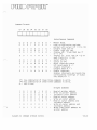
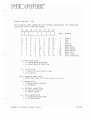
PIED PIPER
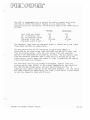
Compare the PIED PIPER against
апу
Competitor
competitor yourself:
It's not the cheapest, it is the BEST VALUE in microcomputers today.
N/A
Standard
170К
Standard
$300
N/A
Standard
Standard
320К
380К
Standard
784К
Standard
Standard
Standard
64К
Para11e1
sk
Printer
Storage
Port
О;
Standard
$60
Standard
СР/М
RAM
$795
$2,699
$1,595
$4,285
$1,299
Pri се
Competitive information extracted from manufacturer's 1iterature for comparison purposes only.
Specifications subject to change without notice.
Compare the PIED PIPER.
Epson
Commodore 64 $179
Kaypro II
Compaq
PIED PIPER
)
)
:1:
~
[iЩ]
~
~
C=J
О
[iЩ]
ГI
~
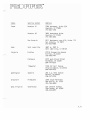
ACCESSORIES
Monitor Stand
Printer
СаЫе
attractive slim stand will allow уои to store your
PIED PIPER and monitor in а convenient setting.
Ап
The PIED PIPER printer саЫе will connect your computer
to апу standard parallel printer (Centronics type).
User's Manual
Replacement User's Manuals are available.
R.F. Modulator
The R.F. Modulator permits уои to use your te1evision
as а display screen. It provides а view of 24 lines of
40 characters with hori zonta 1 scro 11 i ng feature to у; ew
80 columns. It simply plugs into а jack at the back of
the PIED PIPER.
PIED PIPER Carry Case
Provides additional protection while уои are оп the
go. It has storage space for diskettes, electrical
cord. R.F. Modulator and manuals. All this in опе
slim, smart and attractive carrying case.
Diskettes
High quality floppy diskettes that provide reliable
data storage are available. Double-sided, double
density, 96 TPI and а reinforced hub ring are
included. For detai1s, see pages 8 and 9 in this
section.
11.7
The PI ЕО PI PER is:
•
•
•
•
POWERFUL
EXPAN DABLE
PORTABLE
AFFORDABLE
SECTION 111:
PERIPHERALS
IN THIS SECTION:
.
• Floppy Dlsk
• Video Display
• тv Display
• Printer
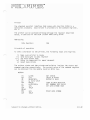
F10ppy Disk Drive:
Add
а
floppy disk drive to your PIED PIPER and you ' l1
have 1.6 megabytes of usab1e storage!
This externa1
disk drive has the same specifications as the
interna1 floppy disk. 8ecause of the high capacity
of this system. 1eave the extra disk behind when
you1re
оп
the go and the PIED PIPER is tru1y
роrtаЫ е. ~
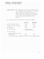
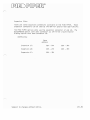
letls crn1pare the two disk PIED PIPER to
а
'пате
brand ' computer:
PIED PIPER
NAME I3RAND
Two Disks Formatted Storage
1568К
380К
Suggested list (with two disks)
$1.850
$1.595
Cost/1000 bytes
$1. 18
$4.20
The PIED PIPER va1ue
1/4 the cost per
Ki10byte of storage
The user advantage:
Storage available when using
Perf ect Writer
190К
560К
PIED PIPER advantage - 295% more avai1able user space
оп
each diskette!
111.2
Video Display:
The PIED PIPER allows the use of апу video
monitor with а 'composite video ' input. (This
excludes а few color monitors.) The recommended
method of viewing the computer
with
а
80х24
video monitor.
Choose the monitor that is right for
large/small; green/amber.
уои
won't
screen.
output is
Ье
And
stuck with
уои
а
yoи~
With the PIED PIPER
smal1. hard-to-see
won't have to lug it around with
уои
if it is not necessary.
опе
for the office.
опе
Виу
two monitors -
for home.
111. 3
TV Oisplay:
Use the PIEO PIPER just about anywhere,because it
has
ап
integral connector for
modulator for use with with
а
а
standard R.F.
television set.
Just think, the PIEO PIPER сап Ье used with
several different types of displays (TV, video
monitor, etc.), so уои don't have to carry а
bulky monitor while you1re traveling. А special
PIEO PIPER program is inc1uded so that standard
80 column disp1ays
t ime.
сап Ье
The program has
а
viewed, 40 columns at
а
hori zont а 1 scro 11 i ng
feature to view 80 columns of text
оп а
regular
te1evision screen.
111.4
Printer Port:
The PIED PIPER has
port built in.
а
standard parallel printer
Use it with high speed dot matrix
printers or letter quality, printers simply Ьу
plugging them into the PIED PIPER. STM supplies
the
саЫе
to ensure trouble-free printing for the
user.
111.5
SECTION IV:
EXPANSION
IN THIS SECTION:
• Second Floppy Drive
• Serial Board
• STD Bus Interface
5erial
Вoard
with two RS232C ports:
тhis serial board option has dual
RS232C ports. Each port has а
0025 рin cormection for use with
standard seri.al type peripherals
such as printers, plotters and
roodems . тhis serial board uses
опе of the expansion board
l<Y"--аtiоns in the PIED PIPER.
IV.2
1
Мbyte
drive
тhe PIED PIPER was designed with mass storage
expansion in mind. А secon f10ppy drive is
easi1y connected Ьу iлstа11ing а new саЬ1е
and adding а back plate. тhe power 1ead is
already in р1асе.
тhe
back p1ate permits rapi p1ug-in and
of both the 1/0 interface as we11 as
the power supp1y.
rerюval
With 2 drives, the user
of online storage.
псм
has 1.6
Мbytes
IV.З
SТD Сапраtiblе ВUs:
тhe edge connector wi11 al10w the PIED
PIPER access to the outside world.
М=>rе infОIиа.tiоп
is avai1ab1e in the
technica1 :jection for users who wish to
knaw the 1/0 positions оп the edge card.
see
page VII, 51-52.
IV.4
[РО[]О [P[I[P[]~M
SECTION V:
WA RAI'JТY AND SERVICE
IN THIS SECTION:
• PI ЕО PI РЕА Service
• List of Хегох Service Centers
• PIED PIPER Limited Warranty
• PIED PIPER Extended Warra.nty
• Initiating the Warranty
• Sarт~ple Warranty Card
PIED PIPER WARRANTY AND SERVICE
STM offers
а
complete service program that includes:
Limited Warranty
90 days from date of purchase
Extended Warranty
1 year - starting when the 90 day
(optional)
limited warranty expires.
Maintenance is performed in authorized locations
Ьу
qualified personnel.
Facilities are conveniently located across the nation.
Nationally/Locally
Xerox Service Centers (listed
оп
the
following pages)
Loca lly
Authorized STM Service Centers
With this serv;ce program for your PIED PIPER.
уои
are assured of
quality. reliable repairs locally or nationwide.
V.2
HOW
ТО
ACTIVATE
ТНЕ
PIED
PIP~R
WARRANTY
We at STM E1ectronics have endeavored to make the process of activating
the PIED PIPER warranty as simp1e, yet complete as possible in order to
protect both the customer and the dea1er.
When the PIED PIPER is sold, simply follow these step
Ьу
step
instructions to activate the end-user's warranty.
first~
1. Complete the sales transaction
2. Remove the warranty registration card from the sleeve located
the outside of the PIED PIPER
З.
Punch out the purchase date
оп
Ьох.
оп
the si1ver registration 1abe1,
piercing the registration card.
4. Comp1ete:
(а)
PIED PIPER seria1 number blank;
information section;
(с)
(Ь)
Dealer
STM software serial numbers;
(d) Extended warranty information section (if applicable).
5. Complete customer
пате,
address and phone number section.
6. Customer should read the end-user agreement acknowledgment and
sign
оп
the blank 1ine where indicated
Ьу
"end-user signature."
7. Customer shou1d comp1ete the persona1 information section.
8. Dea1er should comp1ete the Inspection Report оп the reverse side
of the card.
Note:
only check boxes if the module is defective.
9. Review all sections to ensure that the card has Ьееп complete1y
prepared and then separate and distribute the form as indicated.
1О. Affix the si1ver warranty registration 1abel to the PIED PIPER as
indicated in the picture оп the warranty card.
11 • Mai1 the warranty card to STM E1ectronics.
~
..
V.З
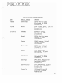
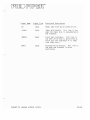
PIED PIPER/XEROX SERVICE CENTERS
State
Service Center
Address
А1аЬата
Birmingham
167-А Citation Court
Birmingham, AL 35209
205-954-1280
Arizona
Phoenix
2109 S. 48th Street, Suite 101
AZ 85282
602-967-1922
Теmре,
Ca1ifornia
A1hambra
614 South Marengo
A1hambra, СА 91803
213-278-0174
Anaheim
232 ~. Cerritos Ауепие
Anaheim, СА 92805
714-776-8143
Carson
20630 Leapwood, Suite
Carson, СА 90746
213-516-6650
Chatsworth
20802 P1ummer Street
Chatsworth, СА 91311
213-709-0226
Oak1and
1981 Adams Street
San Leandro, СА 94577
415-635-9300
Sacramento
4247 S. Market Court
Sacramento, СА 95834
916-920-2275
San Diego
7454 Ronson Road, Suite N
San Diego, СА 92111
619-569-1212
San Francisco
1555 Burke Ауепие, Suite
San Francisco, СА 94124
415-821-7719
Sunnyva1e
Е
В
540 Weddel Drive, #6
Sunnyva1e, СА 94086
408-734-2540
У.4
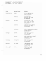
State
Service Center
Address
Co1orado
Denver
8200 East Pacific
Denver, СО 80231
303-696-8966
Connecticut
Hartford
593 Farmington АУепие
Hartford, СТ 06105
203-236-2381
De1aware
Wi1mington
301 Wi11owbrook Lane
Westchester, РА 19380
215-431-0533
F10rida
Ft. Lauderda1e
1500 N.W. 62nd Street, #502
Ft. Lauderda1e, FL 33308
305-491-3202
Jacksonvi11e
3035 Powers Ауепие, Unit #4
Jacksonvi11e, FL 32207
904-731-7218
Miami
6908 NW 72nd Avenue
Miami, FL 33166
305-887-2711
Or1ando
716 North Lake 8ou1evard
A1tamonte Springs, FL 32701
305-830-8109
Татра
6201 Johns Road, Suite 6
Таmра, FL 33614
813-886-0779
Georgia
At1anta
2215 Perimeter Park Dr., Suite 10
At1anta, GA 30341
404-458-1016
Hawa i i
Hono1u1u
627 South Street, Suite 104
Hono1u1u, HI 96813
808-526-0885
Iowa
Des Moines
700 Е. 4th Street
Des Moines, IA 50306
515-282-8700
Р1асе,
Suite 201
V.5
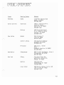
State
Service Center
Address
I11inois
Chicago Loop
165 North Сапа1 Street
Chicago, IL 60606
312-559-9440
E1k Grove Vi11age
2216 Landmeier Road
E1k Grove Vi11age, IL 60007
312-437-3180
Lombard
436А Eisenhower Lane
Lombard, IL 60148
312-953-1113
Springfie1d
2036 S. MacArthur
Springfie1d, IL 62704
217-523-1007
Indiana
Indianiapo1is
5335 West Minnesota Street
Indianapo1is, IN 46241
3187-241-2888
Kansas
Kansas
--
.~
СНу
6383 West 110th Street
Over1and Park, KS 66211
913-381-9819
Wichita
7804 East Funston
Cherry Creek Bus;ness Park
Wichita, KS 67202
316-685-4731
Kentucky
Louisvi llе
10308 B1uegrass Parkway
Louisvi11e, КУ 40223
502-499-7224
Louisiana
Baton Rouge
10466 Air1ine Highway, Suite
Baton Rouge, LA 70816
504-291-5974
New Or1eans
550 Who1esa1ers Parkway, Suite F
Harahan, LA 70123
504-733-1201
К
У.6
State
Service Center
Address
Massachusetts
Boston
248 W. Cummings Park
Woburn, МА 01801
617-938-0845
Braintree
190 Forbes Road
Braintree, МА 02184
617-848-5750
Ва
100 Lakefront Drive
Hunt Va11ey Bus. Сот.
Hunt Va11ey, МD 21030
301-667-8711
Mary1and
1t imore
Rockvi11e
12288 Н. Wi1kens Ауепие
Rockville, МD 20852
301-468-8870
Washington
9730А-l
Detroit
1270 Rankin, $uite
Troy, MI 48084
313-583-2935
Lansing
6810 South Cedar, Suite 7
Lansing, MI 48910
517-694-3350
Minnesota
Minneapolis
3650 Haze1ton Road
Ed i па, r4N 55435
612-920-4472
Missouri
St. Louis
11984 Dorsett Road
St. Louis, МО 63141
314-991-2106
Mississippi
Jackson
870 Fo1ey Street
Jackson, MS 39202
601-948-6302
Michigan
George Palmer Highway
Lanham, МD 20801
301-459-3973
С
~.
У.7
State
Service Center
Address
Nebraska
Omaha
11129 Mi11 Уа11еу Road
Omaha, NE 68154
402-493-0387
North Caro1ina
Char10tte
1838 G Interstate 85
Caro1ina Center
Char1otte, NC 28208
704-399-1523
Ra1eigh
5225 North Bou1evard
#1 N. Commerce Center
Ra1eigh, NC 27604
919-876-1610
Bergen
300-1В Route 17
Lodi, NJ 07644
201-777-4441
New Jersey
Centra1 Jersey
s.
145 A1gonquin Parkway
NJ 07981
201-428-1275
Whippany~
Princeton
248 US Rt. 1 North
B1dg. 1
Monmouth Junction~ NJ 08852
201-329-2050
New Mexico
A1buquerque
5659 Kircher Bou1evard, Suite
A1buquerque, NM 87109
505-344-3563
New York
А1Ьапу
Pine West P1aza Опе
Washington Ауепие Ext.
А1Ьапу, NY 12205
Buffa10
198 Sugg Road
Cheektowaga~
О
NY 14227
716-634-2993
Long Is1and
3000 Marcus Ауепие, Suite
Lake Success~NY 11042
516-437-1134
1-Е8
У.8
State
Service Center
Address
New York
Мапhаttап
405 Lexington Аvепuе
Chrys1er Вui1diпg
New York, NY 10017
212-697-2190
Rochester
333 Metro Park
Rochester, NY 14623
716-424-401 О
Syracuse
7150 Henry С1ау Bou1evard
Liverpoo1, NY 13088
315-451-7420
Tarrytown
5 Westchester P1aza
E1msford, NY 10523
914-592-4454
Ohio
Аkrоп
2650
s.
Аkrоп,
Аr1iпgtоп
Road
ОН
44319
216-644-3251
Ok1ahoma
Сiпсiппаti
4814 Interstate Drive
сiпсiппаti, ОН 45246
513-874-0884
C1eve1and
Тесhпо10gу
Co1umbus
3711 Corporate Dr;ve
Co1umbus, ОН 43229
614-895-3033
Ok1ahoma C;ty
2122 South Меridiап
Ok1ahoma City, ОК 73108
405-682-5030
Tu1sa
4725А
P1aza
5267 East 98th Street
C1eve1and, ОН 44125
216-587-1546
South Memoria1 Dr;ve
Tu1sa, ОК 74145
918-665-0811
У.9
State
Service Center
Address
Oregon
Portland
10110 S.W. Nimbus
Tigard, OR 97223
503-684-1152
Pennsylvania
Harrisburg
806 S. 29th Street
Harrisburg, РА 17111
717 -564-2602
King of Prussia
1006 W. 8th Avenue, Suite
King of Prussia, РА 19409
215-337-4486
Philadelphia
9140 Academy Road, Suite H&I
Philadelphia, РА 19136
215-331-0999
Р i ttsburgh
601 Holiday Drive
Pittsburg, РА 15220
412-921-8202
Hestchester
301 Willowbrook Lane
Westchester, РА 19380
215-431-0533
Nemphis
1835 Nonconnah Blvd., Suite 143
Memphis, TN 37132
901-346-2211
Nashville
1854 Airlane Drive
Nashvil1e, TN 37210
615-883-5102
Austin
7950 Anderson Square, #112
Austin, ТХ 78758
512-451-6263
Dallas
1525 W. Mockingbird Lane, Suite 104
Dallas, ТХ 75235
214-630-6647
Ft. Worth
3273 Crabtree Street
Ft. Worth, ТХ 76111
817 -626-8243
Tennessee
Texas
Ауепие,
8-9
С
У. 1О
State
Texas
Service
Сепtеr
Address
Ноustоп
#1
7280 Wуппwооd, Suite 220
Houston, ТХ 77008
713-862-1784
Ноustоп
#2
3642 Westchase Drive
Ноustоп, ТХ 77042
71 3-789 -3070
San
Апtопiо
2411 Northeast Loop 410, Suite 112
Sап Апtопiо, ТХ 78217
512-655-0085
Utah
Sa1t Lake City
3697 W. 1987 S.
Sa1t Lake СНу, UT 84104
Virginia
Fairfax
27318 Prosperity Аvепuе
Fairfax, VA 22031
703-698-7477
Riсhmопd
8707 West 8road Street
Richmond, VA 23229
804-747-0275
Tidewater
1448 Air Rai1 Аvепuе
Beach, VA 23455
804-464-4752
Virgiпiа
Wаshiпgtоп
Seatt1e
Wisсопsiп
М]
West
Virgiпiа
1waukee
Сhаr1еstоп
266 S.W. 43rd Avenue
Rепtоп, WA 98055
206-251-9155
2995 South Moreland
New Веr1iп, WI 53151
414-784-3690
523 Centra1
Аvепuе
Сhаr1еstоп,
WV 25302
304-342-8015
V. 11
[J)[I~D [J)D[J)~[R{M
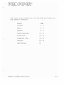
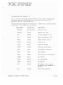
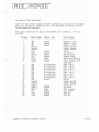
SECTION VII:
TECHNICAL INFORMATION
THIS SEC1-ION CONTAINS А SET OF
PIED PIPER TECHNICAL DАТА SHEETS
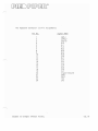
This section contains exp1anations of the PIEO PIPER specifications and
other technica1 information:
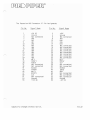
Section
Processor
1 -
2
Memory
3 -
8
Keyboard
9 - 18
Disp1ay
{'
Page
СараЬ; 1 Ну
19
31
Printer Port
32 - 34
Floppy Disk Drive
35 - 49
Expansion
50 - 54
Specifications
55
Subject to changes without notice.
v11. 1
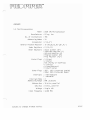
HARDWARE
1.0 The Microprocessor
Mode1
Manuf acturer
No. of 1nstructions
Addressing Modes
Accumu1 ator
General Purpose Register
Z80A CPU Microprocessor
Zi1og, lnc.
158
10
2 (A,A 1 )
12 (В С, DЕ , HL , ВС' , ОЕ ' , HL
1ndex Registers
2 (1X,1Y)
Other Registers
Stack pointer (SP)
1nterrupt Register (1)
Refresh Register (R)
Program Counter (РС)
Flag Register (F,F 1 )
Status Flags
I )
S (Sign)
Z (Zero)
P/V (Parity or Overflow)
С (Carry)
N (Add/Subtract)
н (Ha1f Carry)
Other F1ags
1nterrupts
1nterrupt Mode
Addressing Range
Address Bus
Data Bus
Vo lt age
C10ck Frequency
Subject to changes without notice.
1FF1, 1FF2 (1nterrupt ЕпаЫе)
1MF а, 1MFb (1 nterrupt MOde)
1 Non-maskab1e
1 Maskable
3
64К
Locations
16 bits, para11el
8 bits, para11el
Sing1e +5V
4.000 MHz
V11.2
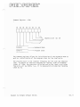
The processor gets its timing signal 4.000 MHz clock from the clock
generator circuit which uses
8.000 MHz crysta1 as its time basis.
ап
Other clock timing like the 2 MHz and 1 MHz clock for peripheral
control1ers are obtained
Ьу
using
а
counter
74LS1бl
to sca1e down the
system c1ock.
The microprocessor has
address bus lines
bus lines
D~0-087
а
address bus and
1б-Ьit
АВО-АВ7
are buffered
are buffered
Ьу а
Ьу а
ап
8-bit data bus.
The
buffer 74LS244, and the data
tri-state buffer 74LS245.
The BUSRQ, HALT/,NMI/,INT/ and WAIT/ are held high Ьу 1К Ohm resistors to
+5V. I/O write and read signa1s are decoded Ьу 10gic gates using signa1s
IORQ/, WR/ and RD/ from the CPU.
The RFSH/ signal is used
Ьу
the Memory Refresh Circuitry to prov;de the
signal necessary for dynamic memory refreshing.
Subject to changes without notice.
VI I. 3
(
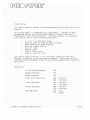
Memory Organization
The P1ED PIPER has
the fol1owing:
а
total memory capacity of
64К RAM system memory
4К bootstrap ROM
2К RAM display memory
2К character generator
72К
bytes.
These include
ROM
Only the bootstrap ROM and the system memory uses the Z80A processor
memory address lines. The display memory is accessed through 1/0
addresses, and the character generator ROM is accessed solely Ьу the
video display controller.
Although the bootstrap ROM is only 4К bytes in size, the P1EO P1PER is
сараЫе of accommodating ROM of up to lБК bytes in size.
Both the system
memory and the bootstrap ROM share the memory addresses from 0000 hex to
7FFF hex, but only опе will Ье activated at any given time. When the ROM
is enabled, accesses to memory address 0000 to 7FFF hex will Ье directed
to the ROM. When the ROM is disabled, accesses will Ье directed to the
system RAM memory.
The bootstrap RUM contains tlardware initialization procedures, self-test
diagnostics, and bootstrap routine for Dringing in the first sector of
the first track оп the floppy disk. The content of this ROM is copied to
RАГ>') starting from location OFOOO hex after some рrеlimiпаrу self test.
The ROM is then disabled, and the remaining seTf tests plus the bootstrap
procedure are executed from the R~~ area.
Г',
Subject to changes without notice.
v11.4
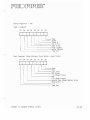
ООООН
Page
OOFFH
OlOOH
О,
reserved for CPjM
Transient Program Area
(ТРА)
OCBFFH
ОССООН
Console Command Processor
(ССР)
OD3FFH
ОD400Н
Basic Disk Operating 5ystem
(8005)
OE1FFH
ОЕ200Н
OF4FFH
OF500H
OFAFFH
OFBOOH
OFBOFH
OFB10H
Basic Input Output System
(BI05)
Reserved Area for Option
Card Programs
Interrupt Vectors
Interrupt Handling Routines
+
Disk InputjOutput Routines
+
Reserved Data Area
+
Jump Vectors for Usefu1
Rout i nes
OFFFFH
5ubject to changes without notice.
VII.5
ROM Memory
The PIED PIPER Boot Utility Program is stored оп а 32К bits PROM which
occupies memory address from ООООН to OFFFH. The circuit is designed to
accommodate ROM of up to 128K bits in size which will then occupy memory
address from ООООН to ЗFFFН.
In order to fully utilize the 64К bytes RAM address capability for the
system. both the RAM and ROM will occupy the same memory address from
ООООН to 7FFFH.
However, only опе wi11 Ье activated at any given time.
The ROM SELECT flag dictates which of the two is to Ье activated. If the
ROM SELECT flag is set. the ROM will Ье enabled, and if it is off, then
RAM will Ье selected. The RAM address from 8000Н to FFFFH is independent
of the flag and is accessible all the time.
When the system is reset, the ROM SELECT flag is set Ьу the RESET line.
Hence the RAМ from address ООООН to 7FFFH is disabled and RQM memory is
activated. The stored program in the ROM will then start loading the
СР/М Operating System from the system diskette onto the RAM.
When
completed. the ROMSEL/ bit is set high. and а read Status Register
instruction will Ье issued which will set off the ROM SELECT flag.
Thereafter. the lower portion RAM will resume its memory address, and we
will get the full б4К bytes of memory storage.
Subject to changes without notice.
VII.б
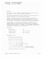
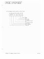
ROM Size Se1ection Jumper
The jumper JU insta11ed оп the board сап
that сап Ье insta11ed in the ROM socket.
Ье
used to se1ect the ROM size
When jumper to JU2 is connected to +5V, ап 8К х 8 bit ROM сап Ье
insta11ed in the socket. When trace to JU2 is cut and jumper to JU1 is
connected to А13, а 16К х 8 bit ROM сап Ье used. The existing board is
with JUl connected to А13.
ROM SOCKET PINOUT
А01
АОО
1
2
3
4
5
6
7
8
9
10
000
001
002
GNO
12
13
14
+5V
А12
А07
А06
А05
А04
А03
А02
11
SUbject to changes without notice.
28
27
26
25
24
23
22
21
20
19
18
17
16
15
+5V
+5V
*JU2 +5V
----- ----*
А08
*JUl
А13
АО9
А11
ОЕ/
A10
СЕ/
007
ООб
005
004
003
Vll.7
RAM Memory
The PIED PIPER uses eight б4К х 1 bit Dynamic ~AMs for its 64К bytes
memory storage. The memory address is from оооан to FFFFH.
The address for RAМ is provided Ьу two address multiplexers wh;ch give
the low and hi g~l address byte to RAMs, dependi ng оп the st atus of Row
Address Strobe RAS/ and the Column Address Strobe CAS/.
The data lines are direct1y tied to the system data bus, and data
read/write mode is se1ected Ьу the write enable line WE/. А 10g;c high
оп the WE/ se1ects the read mode, and а 10gic low se1ects the write mode.
The Dynamic RAMs are automatica11y refreshed during the instruction fetch
cycles. The CAS/ 1ine is set high when the refresh signal 1;пе RSH/ is
low to avoid апу data output during refresh. When RFSH/ and MREQ/ are
10w, the RAS/ 1ine takes the 10wer system address byte as а refresh
address and causes а11 bits in each row to Ье refreshed.
Subject to changes without notice.
v11.8
О;
spl ау Memory
The video display control1er uses information in the display memory to
generate its display. The value stored in а disp1ay memory location
controls the character block to Ье displayed оп the monitor. The value
is а regular 7-bit ASCII va1ue. The most significant bit denotes high
intensity or low intensity when the highlight mode is selected. If the
reverse video mode is selected, the display ~ill Ье in reverse video or
regular video, depending оп the value of the most significant bit.
The display memory address starts from 0000 hex to 07FF hex. The screen
start registers contain the starting address of memory that corresponds
with the top left hand corner of the disp1ay screen. The contro1ler is
smart enough to automatical1y wrap around the display memory so that the
screen start address сап Ье changed dynamically. As ап example. the PIEO
PIPER uses а 24 Ьу 80 display and the display buffer starting address is
initia1ized to 0080 hex. The number of memory cells from 0080 hex to
07FF hex is 1920, which is equal to 24 times 80. If the screen start
registers contain 0120 hex, the memory location at this address will
represent the top left hand corner of the display. Dие to the wrap
around nature, memory address OllF hex will represent the lower right
hand corner of the display.
The cursor registers contain the memory address of the current cursor
position оп the monitor. For example, if the screen start address is
0120 hex, and the cursor is оп the first column of the third 1ine, the
cursor registers wil1 contain the address 01СО hex.
The pointer registers are used most of the time for initializing а
portion of the display memory to а certain value. This is accomplished
Ьу using опе of the controller commands to write from the cursor position
to the pointer position. Continuing the above ехатр1е, to blank out the
third line of the display, a11 опе has to do is to modify the pointer
registers to equal to the cursor registers plus 80 (for 80 columns), and
then i ssue the "wri te cursor to ро; nter" command to the command reg i ster.
Subject to changes without notice.
v11.9
Keyboard
The keyboard is опе of the main communication too1s for the user
PIEO PIPER. А11 user inputs are through the keyboard.
оп
the
The PIEO PIPEk keyboard has 61 keys. Except for а few specia1 keys, the
keyboard resembles а ful1 sized typewriter keyboara.
Except for the FUNCT, CTRL, SHIFT, and CAPS LOCK keys, which do not
generate а code Ьу themse1ves, а11 other keys generate а 6-bit va1ue.
The CTRL, SHIFТ, апа FUNCT keys contribute the remaining 2 bits to t'orrn
ап 8-bit code.
This 8-bit code is accessible through the data register.
A1though there is по repeat key оп the keyboard, Ьу pressing а key
without re1easing it for more than опе second, the key is duplicated
automatica11y until the key is released. This auto repeat feature does
not work with the FUNCT key. This feature is imp1emented Ьу software and
is described in more detai1 in а later section.
Addressing
Oata Register:
08Н
Command Register:
09Н
- Write only
Status Register:
09Н
- Read
Oata Register 07
06
05
оп1у
08Н
04
03
02
01
00
'--~----~/
6-bit value
,/
"'------------ =
'--------------- =
Function
Кеу
Pressed
==е
О
07 and 06 =
Subject to changes without notice.
Sflift Кеу Pressed
Contro 1 Кеу Pressed
О
О
VII.10
Command Register -
07
Об
05
04
09Н
03
02
01
00
Oepend
1010101
- - - Keyboard Mode
1010111
' - - - Prograrn Clock
оп
07
Об
05
The command register a110ws for initia1ization of the keyboard mode as
we11 as initia1ization of the program c10ck for the scan сус1е.
The program clock is the internal frequency for the scan and debounce
time. То obtain an interna1 frequency of 100 KHz, with an incoming
signa1 of 1 MHz. the presca1er va1ue defined Ьу the 1east significant
five bits wi11 Ье 01010, i.e., it is necessary to divide the incoming
c10ck Ьу 10.
Subject to changes without notice.
VII.ll
Status Register -
07
Об
05
04
09Н
03
02
01
00
1---- ------Т- -т--т--т--т-- ]
) Number of keys i n buffer
FIFO fu11
- - - - - - - - - - Error underrun
L.....--Error overrun
, - - - - - - - - - - - - - Sensor closure
,--------------~
Oisp1ay unavai1able
Initia1ization
ехатр1е
То initialize the keyboard for
frequency:
LO
А,ООООООООВ
ОИТ
09Н,А
А,ОО101010В
09Н,А
LD
ОИТ
а
2-key lockout and 50 KHz operating
SET ENCOOEO SCAN &
2 КЕУ LOCKOUT
SET UP PROGRAM CLOCK
Auto Repeat
When а key is pressed but not released. the decoding circuitry оп1у
reports а sing1e key pressed event. In order to imp1ement the auto
repeat feature, the decoding circuitry must Ье tricked into thinking that
the key has Ьееп released and pressed again. То accomplish this, the
keyboard scan must Ье disаЫеd and then enabled again to simulate а key
release and press action. The timer is used extensively in control1ing
the frequency of the аЬоуе simulаtiоп.
Subject to changes without notice.
VII.12
Decoding
The 8-bit value from the data register is used to translate the key
pressed into the appropriate ASCII value of the key before the operating
system retains control. The non-translated value сап Ье obtained
directly from the data register.
Although the CTRL~ SHIFT and FUNCT keys alter the 8-bit value of the data
register, the same does not apply for the CAPS LOCK key. The latter key
only alters the translated value. CAPS LOCK causes all lower case
alphabetic values to Ье transformed into upper case.
The CTRL key works with all alphabetic letter keys, plus the following:
- shift 2
- shift б
- [
]
\
- shift -
-
All other keys are translated as if the CTRL key is not pressed.
The 5HIFT key works the same way as оп а typewriter; i.e.~ letter keys
are capitalized, and special characters above the number keys are
produced.
The FUNCT key works with all alphabetic letter keys, the number keys
except 2 and 6, and the arrow keys.
The numeric functions апа the arrow functions are reserved for the
horizontal scrolling under the TV display and also for display
manipulation under Liquid Crystal Display option. The alphaDetic letter
functions сап Ье decoded Ьу calling the СР/М CONIN 8005 function. The
translated value of а function key has the most significant bit set.
r
Subject to changes without notice.
VII.lЗ
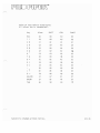
Va1ue of keys before trans1ation.
values are in hexadecima1.
А11
Кеу
~.
А1опе
SHIFT
CTRL
FUNCТ
ESC
СО
80
40
00
1
С8
88
48
08
2 @
С1
81
41
01
3 #
С9
89
49
09
4 $
СА
8А
4А
ОА
5 %
С2
82
42
01-
б
СЗ
аз
43
03
7 &
С8
813
4В
013
*
СС
8С
4С
ОС
9 (
С4
84
44
04
О )
С5
85
45
05
СО
8О
4О
ОО
+
СЕ
8Е
4Е
ОЕ
i~
С6
86
46
06
DELEТE
С7
87
47
07
BREAK
CF
8F
4F
OF
ТАВ
Оо
90
50
10
8
=
~
Subject to changes without notice.
VII.14
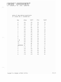
Va1ue of keys before trans1ation.
va1ues are in hexadecimal.
А11
Кеу
Alone
SHIFТ
CTf<L
FUNCT
Q
08
98
5~
18
W
09
99
59
19
Е
01
91
51
11
R
02
92
52
12
Т
ОА
9А
5А
1А
У
ОБ
98
58
18
U
03
93
53
13
1
04
94
54
14
О
ОС
9С
5С
1С
Р
00
90
50
1D
[l
05
95
55
15
]}
06
96
56
16
\1
ОЕ
9Е
5Е
1Е
8ACKSPACE
DF
9F
5F
1F
А
Е1
А1
61
21
S
Е9
А9
69
29
О
ЕА
АА
6А
2А
F
Е2
А2
62
22
G
Е3
А3
63
23
Subject to changes without notice.
VII.15
Va1ue of keys before trans1ation.
All va1ues are in hexadecimal.
Кеу
А1опе
SHIFT
CTRL
FUNCТ
Н
ЕВ
АВ
6В
28
J
ЕС
АС
6С
2С
К
Е4
А4
64
24
L
Е5
А5
65
25
ЕО
АО
60
20
ЕЕ
АЕ
6Е
2Е
RETURN
Е6
А6
66
26
LINE FEEO
Е7
А7
67
27
Z
F9
В9
79
39
Х
Fl
81
71
31
С
F2
В2
72
32
V
FA
ВА
7А
3А
В
FB
ВВ
7В
311
N
F3
В3
7з
33
М
F4
В4
74
34
,<
FC
ВС
7С
3С
.>
FO
ВО
70
зо
/
?
F5
В5
75
35
--t
F6
В6
76
36
FE
ВЕ
7Е
ЗЕ
F8
88
78
38
I
11
-'
SPACE 8AR
Subject to changes without notice.
VII.lб
The Keyboard
The keyboard controller is built around the Intel 8279 programmable
keyboard controller and inferfaces with the keyboard via the connecting
саЫе at Connector J13.
The controller rapidly scans through the column lines CLO-CL7 of the key
matrix оп the keyboard. Its row values from the returned lines RLO-RL7
are latched and scanned for key closure ;п that row. When а low is
detected in апу of RLO to RL7 lines, а key closure is found and а
debounce circuit is activated to check if it ;s а proper key switch
depression. If the closure is shorter than 20 msec. ;t is regarded as а
bounce. and the controller looks for another key closure. Otherwise, the
key position ;s returned together with the status of the CONTROL and
SHIFT lines and stored into the controller's character buffer.
When а key closure is detected and lasts for more than 2 seconds, the
keyboard is disabled Ьу setting off the K8REL line and then reenabled
again to check for key depression. If а key closure is detected and the
key value is the same as that previously stored in the controller's
character buffer. the key is placed in the auto repeat mode. The K8REL
line is disabled and reenabled every 0.05 seconds to generate а multiple
key closure effect. This process is repeated until the key is released.
If по key or а different key closure is detected at апу time after the
KBREL line is reenabled, the keyboard scan cycle is repeated.
Subject to changes without notice.
VII.17
The Keyboard Connector J13
This is а 24-pin male connector which is used to connect with the
built-in typewriter-1ike keyboard assembly. The signa1 descriptions for
the connector are as fo1lows:
Signal Name
Signa1 F10w
functiona1 Description
CLO-Cl7
Output
Соlитп scan 1ines which are used to scan
the key switch c1osure. SL7 is the most
significant co1umn line number.
RLO-RL7
Input
Return 1ine inputs. These 1ines shou1d Ье
pu11ed high unti1 а switch c10sure in the
row pu11s it to low. RL7 is the most
significant row number.
CNTl/
Input
This line should Ье low when "CTRL 11 or
"FUNCT" key is depressed.
SHIFТ/
Input
This line should Ье low when
"FUNCТ" key is depressed.
КЕУ
DEPRESSION
CNTL/
SHIFТ/
FUNC
Low
Low
Н; gh
High
Low
High
Low
Н; gh
CТRL
SHIFT
NIL
IISHIFТ
II
or
CAPLK/
Input
This line should Ье low when capital lock
key "CAPS LOCK" is depressed.
COO/-C01
Output
Drive select indicators. СОО/ is low when
Drive 1 is se1ected. C01/ is low when
Drive 2 is selected.
SPK
Output
Audio signal output to speaker mounted
the РСВ board.
Subject to changes without notice.
оп
VII.18
The Keyboard Connector J13
Р;
n Assignments
Pin No.
1
2
3
4
5
6
7
8
9
10
11
12
13
14
15
16
17
18
19
20
21
22
23
24
Subject to changes without notice.
Si gna 1 Name
CNTL/
CAPLK/
SHIFТ/
RLO
RL 1
RL2
RL3
RL4
RL5
RL6
CLO
RL7
CLl
CL2
CL3
CL4
CL5
CL6
CL7
Signal Ground
СО 0/
С01/
+5V
SPK
VII.19
Video Display
The video display is another vital communication tool for the user
compute r .
оп
the
The display memory is independent of system memory. Transfer of data
between the CPU and the display buffer memory is controlled Ьу the
Programmable Video Timing Controller. The video display is а character
block display and has the fol1owing capabilities:
8 х 9 or 7 х 9 character block
White оп black or black оп white displacy
High intensity or mono-intensity
80 or 40 columns display
24 or 25 1i nes
Reverse video
Line or block cursor
Blink or no-blink cursor
The video display controller is ап intelligent controller with тапу
features in addition to the ones described аЬоуе. P1ease refer to the
Signetics 2672 Programmable Video Timing Controller Application Notes for
more detai 1.
Addressing
1nit i а 1i z а t i оп Reg i s t е r :
ООН
Соmmапd
Register:
Status Register:
OlH
Sсrееп
02Н
Start Registers:
01Н
ОЗН
Cursor Registers:
04Н
05Н
Роiпtеr
Registers:
06Н
07Н
Data Registers:
ООН
1СН
Subject to
сhапgеs
without
поtiсе.
-
low byte
high byte
low byte
high byte
low byte
high byte
iпрut
output
V11.20
Initialization
Initia1ization of the video disp1ay chip involves se1ecting the video
disp1ay mode through the mode register and a1so supp1ying the va1ues to
the 11 initia1ization registers.
The norma1 start up condition of the video disp1ay chip is: 7 х 9
character block, white оп b1ack screen, 2К character set, high intensity,
and 80 co1umns disp1ay.
а
The cursor is
non-blink block character.
Initia1ization Registers -
The aisp1ay is 24 1ines.
ООН
There are 11 initia1ization registers (lRO - lR10) which are accessed
sequentia11y via а sing1e address. The contro11er maintains ап internal
pointer to these registers which is incremented after each write at this
address until the 1ast register (lR10, the sp1it screen register) is
accessed.
The fo11owing values are for the setting as described in section 5.2.
IRO
lR1
IR2
IR3
IR4
IR5
IRб
IR7
IR8
IR9
lRl0
О
О
О
О
О
О
О
О
1
О
О
О
1
1
О
О
1
1
О
О
О
О
1
1
О
О
О
О
О
1
О
О
О
О
О
О
О
1
Command Register
О
О
О
О
1
О
О
О
1
1
О
1
1
О
О
О
44Н
О
1
О
ббН
1
1
4FH
32Н
О
О
1
1
1
1
1
1
1
1
О
О
О
О
О
08Н
1
1
09Н
О
О
О
80Н
О
О
О
О
О
О
О
О
О
ОЕН
17H
10Н
80Н
OlH
The video disp1ay control1er commands are divided into two c1asses: the
instantaneous commands, which are executed iroolediately after they are
i nvokgd, and the delayed commands which тау require а delay for а
blanking interva1 prior to their execution.
Subject to changes without notice.
VII.21
Command Formats
07
И6
05
04
DЗ
02
О1
ОО
Instantaneous Commands
О
О
О
О
О
О
О
1
V
V
V
V
d
d
1
d
d
N
1
О
Т
1
О
d
d
d
d
О
О
О
d
N
d
О
о
О
о
1
1
О
1
О
О
О
О
О
О
О
О
О
О
d
d
N
d
d
N
d
d
N
О
О
1
1
N
О
N
N
N
N
N
N
N
N
N
N
О
Апу
(*)
(**)
d =
Апу
Ооп'
1
N
Master Reset
Load initialization register
pointer with value V (V = о to 1О)
Disable 1ight реп (*)
ЕпаЫе 1ight реп (**)
Di sp 1ау off. Float ОАОО bus if
N = 1 (*)
Display оп. Sc ап 1i пе (N = о) or
next field (N = 1) (**)
Cursor off (*)
Cursor оп (**)
Reset interrupt/status
8it reset where N - 1
Disable interrupt.
Disable where N = 1
ЕпаЫе interrupt.
Enables interrupts and resets the
corresponding interrupt or status
bits where N = 1.
combi nat i оп of these three commands is val id.
combination of these three commands i s valid.
t care.
Ое 1ayed
О
1
О
О
О
О
О
О
О
О
О
О
О
1
О
1
1
О
О
О
1
О
1
О
О
О
О
1
1
О
1
О
О
О
1
О
О
О
О
Subject to changes without notice.
О
1
Command s
Read at pointer address
Write at pointer address
Increment cursor address
Read at cursor address
Write at cursor address
Read at cursor address and
increment address
Write at cursor address and
increment address
Write from cursor address to
pointer address
VII.22
Status Register - OlH
07
Об
05
04
03
02
01
00
I~I~::с:::::::::::-liI1]
Light
Реп
Ready
'-------Sp1it Screen
' - - - - - - - - - Line Zero
' - - - - - - - - - VBLANK
' - - - - - - - - - - - - - RDFLG
ROFLG - А "zero ll indicates that the contro11er is current1y executing the
previous1y issued command. А " 0пе " indicates that the controller is
ready to accept а new command.
VBLANK - This indicates the beginning of а vertical blanking
i nterva 1. It i s set to а Ilone'l at the beg i пп; ng of the f i rs t sc ап 1i пе
of the vertical front porch.
Line Zero - It is set to а "опе" at the beginning of the first scan 1ine
(line О) of each active character row.
Split Screen - This bit is set when а match occurs between the current
character row number and the value conta'1.1ed in the split screen
interrupt register, which is set at initia1ization time.
Ready - Certain commands affect the display and тау require the
controller to wait for а Ыапkiпg interval before enacting the command.
This bit is set to "oп€" when execution ot' the command is completed.
Light Реп - А "Oп€" i ndicates that а 1ight реп hit has occurred and that
the contents of the light реп register have Ьееп updated.
Subject to changes without
поtiсе.
VII.23
Data Registers - ООН (Read) and 1СН (Write)
The data regi sters are used for stori ng and retrievi ng data to and from
the display memory. These registers must Ье used together with опе of
the de1 ayed commands.
Examples:
1.
C1ear disp1ay to blank at start
ир.
NOTRDY:
IN
AND
JR
LD
OUT
LD
OUT
LD
OUT
LD
OUT
LD
OUT
LD
OUT
2.
А,ОlН:
20Н:
Z,NOTRDY:
А,20Н:
lCH,A:
А80Н:
04Н.А:
А,ООН
05Н,А
A.OFFH:
06Н.А:
А.07Н:
GET STATUS
СНЕСК IF READY
REPEAT 1F BUSY
SET ТО INITALIZE ТО BLANKS
SEND ТО ОАТА REGISTER
INITIALIZE CURSOR REGISTERS
ТО ТОР LEFT CORNER OF SCREEN
INITIALIZE POINTER REGISTERS
RIGHT CORNER
OF SCREEN
ТО ВОТТОМ
07Н,А:
А,10111011В
OlH,A:
WRITE CURSOR
ТО
POINTER
Read back content of disp1ay memory at cursor position.
LD
OUT
NOTRDY:
IN
AND
JR
IN
А,10101100В:
READ
АТ
CURSOR
01Н.А
А,ОlН:
20Н:
Z.NOTRDY:
А,ООН:
Subject to changes without notice.
GET STATUS
СНЕСК IF READY
REPEAT IF BUSY
READ ОАТА FROM
ОАТА
REGISTER
VII.24
Termina1 Emulation
The video display as hand1ed Ьу the СР/М CONOUT BDOS function emulates а
Hazeltine 1500 terminal. То configure application programs such as
Wordstar, which makes use of screen functions, select the Haze1tine 1500
as the termina1 during the insta11ation procedure.
А11
functions of the Hazeltine 1500 are emu1ated, except the fo11owing:
Fie1d ТаЬ
Block Mode
In addition to the above functions, the following functions are added:
Turn cursor ON
Turn cursor OFF
Turn di sp 1ау ON
Turn disp1ay OFF
Graphic character
Lead-i п, SOH
Lead-in, STX
Lead-in, ЕТХ
Lead-in, ЕОТ
Lead-i п, RS, char
(7EH,OlH)
(7ЕН,О2Н)
( 7ЕН,03Н)
(7ЕН,04Н)
(7ЕН,lЕН)
The graphic character function a110ws app1ication programs to uti1ize the
special table-drawing character set.
Subject to changes without notice.
VII.25
Reverse Video
Reverse video is accomplished
mode register.
Programming
Ьу
setting the reverse video bit ln the
ехаmрlе
LD
RES
А,
SEТ
1,A:
(OFFEOH),A:
lDH,A:
LD
OUT
(OFFEOH):
2,А:
GET CURRENT VALUE
RESET HIGH INTENSITY
SET REVERSE VIDEO
SAVE CHANGED VALUE
UPDATE rvЮDЕ
Character Set
Basically the normal character set as found in most terminals is
supported. Exceptions are:
The British pound sign
IIfll
replaces the single back quote
11
11
Graphic characters for drawing table are included.
When displaying, the 7-bit ASCII value of а character is supplied to the
Video Display Controller. The most significant bit is used to indicate
highlight or reverse video, depending оп the mode selected.
Subject to changes without notice.
VII.2б
О
L
О
г
2
r~
-..
3
4
5
О
@
р
А
Q
а
q
6
7
р
2 .-1
::.
11
2
В
R
Ь
r
-,
...::.
#
3
С
S
с
5
4 -L
Г
$
4
О
Т
d
t
5 Т
L
%
5
Е
U
е
u
~
О
&
r/.
F
V
f
v
.1.
7
G
W
9
w
+
8
Н
Х
h
х
+
9
1
У
*
J
Z
J
+
k
[
k
]
m
3
6
7
~
8 С;-с.
9
А
~
+ ....
I
В
-
С
\.
О
::>
Е
F
j
Q
z
L
=
.6
о
у
/
?
м
N
n
О
о
The character generator ROM contains information required Ьу the video
disp1ay contro11er to display each character.
Each character is defined
in the ROM Ьу 16 bytes. The first nine bytes are determined from the
coding of 9 rows Ьу 8 co1umns matrix. This matrix is first used to
determine the dots location for а particular character. The hex value of
each row then constitute ап 8-bit value. These 9 rows thus define the
first 9 bytes for the character and the remaining bytes for the character
are zeros.
Subject to changes without notice.
VII.27
The Video Display Control1er
The video disp1ay controller consists of а Signetics 2672 programmable
video timing controller (PVTC), 2К bytes of display buffer memory, а
disp1ay character generator kUM, and video and atrribute control
с; rcuitry.
1he display buffer does not take апу memory space in the system RAM, as
it has its own 2К bytes of interna1 memory for storage of опе fu1l screen
of disp1ay characters. It is made ир Ьу four 1024 х 4 bits static RAMs.
The PVTC derives its timing from ап external character c10ck generator
which uses а 13.000 MHz crystal as its time basis and generates al1 the
disp1ay timing, inc1uding scan line per character row, video dot timing,
composite sync and other contro1 signals necessary for the display data
оп а CRT termina1.
It a1so provides consecutive addressing to the display buffer memory and
controls the CPU-display buffer interface. Transfer of data between the
CPU and the display memory is accomplished via а write display buffer and
а read disp1ay buffer which is contro1led Ьу the signa1s write data
buffer WRD/, read data buffer RDB/ and buffer chip епаЫе СЕ/.
During а write operation, data is loaded Ьу the CPU into the write
display buffer, and the PVTC outputs the specified disp1ay buffer address
and activates the WRD/ and СЕ/ signa1 to complete the operation.
During а read operation, the CPU issues а read command and the PVTC
outputs the disp1ay buffer address and activates the RD~/ and СЕ/ to
1atch data from the disp1ay buffer onto the read disp1ay buffer. When
the CPU detects the ready flag set Ьу the PVTC, it reads data from the
read disp1ay buffer.
Data transfer is performed during the blanking interva1 in order to
prevent visual disturbance of the display data.
Subject to changes without notice.
VII.28
The PVTC is programmable for а variety of display formats and timing
profiles оп either the monitor display or оп а television. The
characteristics for the monitor and television mode сап Ье summarized as
f 011 ows :
Scan lines per screen
No. of character row
No. of character column
Character clock time
Character width in dot
Monitor
Te1evision
216
24
216
24
80
13.0 MHz
8
40
6.5 MHz
7
The character clock time апа character width is control1ed
lines 40COL and DIV7-8/ respective1y.
('"
Ьу
the signal
The dot pattern disp1ay for characters in the display memory is
controlled Ьу the scan co1umn 1ines DАDЗ-DАD7 and the ASCII value read
from the disp1ay buffer. 80th the scan column lines and character
address 1ines ОАDО-DАО9 are provided Ьу the PVTC. The aot pattern read
from the character generator ROM is then seria11y shifted out to the
video contro1 circuit where the composite video is generatea and special
visual attributes are produced.
The attribute circuitry сап produce highlighted, reverse video and
black-on-white videa effects оп the screen, depending оп the signals of
HIL, REV and 80W respective1y, and also the attribute bit СС7. А
composite sync signal conforms to the EIA RS170 Standard. А11 the timing
and video signals are generated Ьу the video circuit which is then output
to both the composite video and RF jacks.
SUbject to changes without notice.
VII.29
The Video Connector J2
This is ап RCA phone jack connector for hook up to
monitor compatible with the RS170 standard.
апу
standard video
The pin assignments for the interface signals are as follows:
Pin No.
Oescription
Composite video signal of
approximately 1.5v peak to peak
amplitude into ап 75 ohm load
impedance.
2
Subject to changes without notice.
Chassis ground.
VII.ЗО
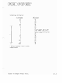
The RF Video Connector J4
This is а 5 pin Oin type socket compatible with the ASTEC UМ1З81 video
modulator or any FCC approved video modulator with the same pinout and
signal configuration.
The pin assignments for the video connector are as follows:
Pin No
Oescription
12V
ОС
supply
2
Video shield ground:
OV
3
Audio Out. 1.OV
р-р:
АС
coupled.
4
Video Uut. O.8V
р-р:
АС
coupled.
5
Not connec ted.
Socket Pinout Oiagram
Subject to changes without notice.
VII.Зl
Printer
The standard parallel interface that comes with the PIEU PIPER is а
Centronics standard. Data strobe is provided via the command register,
ЬН 3.
The printer сап Ье accessed directly through the register described
below, in addition to the СР/М LISTOUT BOOS entry point.
Address i ng
Oat а Reg i ster:
ООН
Principle of operation
То
send
i)
ii)
iii)
iv)
v)
а
character to the printer, the following steps are required:
Make sure printer is ready
Send data byte to data register
Set data strobe high
Оеlау to compensate for paper movement
Reset data strobe
The printer status and data strobe manipulation involves the status and
command register respectively. The current value of the command register
сап Ье obtained from the memory location OFFE2 hex.
NOTRDY:
IN
8IТ
A,18H:
5.А:
JR
LD
OUT
LD
NZ,NOTROY:
А, data value
SEТ
3.А:
18Н,А
OUT
DELAY
RES
OUT
ООН,А:
А, (OFFE2H):
3,А:
GET STATUS
СНЕСК IF REAOY
REPEAT IF HUSY
SENO ТО ОАТА REGISTER
GET COMMAND REG. VALUE
SET ОАТА STROBE HIGH
RESET
DАТА
STR08E
18H ,А
Subject to changes without notice.
vll. 32
The Para11e1 Printer Port
This is а 15 pin D-type fema1e connector which сап hook up to апу
Centronics СОЩJаtiblе printer. It consists of eight bit data 1ines and
two contro1 lines for printer handshaking. The signa1 descriptions are
as follows:
Si9 па 1 Name
Si9na1 F10w
DATA1-DATA8
Output
Data L i nes. These eight data 1; nes
are used to transmit data to the
printer. DАТА8 is the most
significant bit.
DSTA
Output
Data Strobe. The pri nter should use
this signal line to strobe in the
d at а оп t he d at а 1i пе s •
PRBUST
Input
This 1ine shou1d Ье high when printer
i s busy or not ready to recei уе d ata
from the printer port.
Subject to changes without notice.
Description
VII.ЗЗ
Para11el Pri nter Connector JЗ Pin Assignments
Pin No.
Signa1 Name
1
2
DАТА1
3
4
5
DАТАЗ
б
7
8
9
10
11
12
13
14
15
ОАТА2
DАТА4
DАТА5
DАТАб
DSTR
PRBUSY
DАТА7
DАТА8
GROUND
GROUND
GROUND
GROUND
GROUND
.~
Subject to changes without notice.
VII.З4
F10ppy Oisk
The f10ppy disk is the too1 Ьу which programs and data are loaded into
memory. The disk drive that comes with the P1EO P1PER is а 5-1/4" f10ppy
disk drive. The f10ppy diskettes are double sided. double density and 96
tracks per inch. The unformatted сарасНу is 1 Mbyte. and the formatted
capacity is 800 Kbyte.
Although опе сап a1ways use the contro11er register set to perform disk
1/0. some of the basic operations are a1ready avai1able from the
bootstrap ROM. These routines, which are a1so used Ьу the СР/М operating
system. are described in more detai1 in the usefu1 routines section.
Address i ng
Command Reg i ster:
10Н
- Write
Status Register:
10Н
- Read
т r ас k
11 Н
Reg i st е r :
,"---
Sector Regi ster:
12Н
Оаt а
13Н
Reg i st е r :
оп 1у
оп1у
1nitia1ization
No special initialization is required for the f10ppy disk control1er.
The diskette that is to Ье used оп the P1ED P1PER. together with the СР/М
operating system. must first Ье formatted. The userls тапиаl has а
detailed description оп the utility program that does this.
Subject to changes without notice.
VII. 35
Command Register - lOH
The fol1owing table summarizes the commands supported
contro11er used in the PIEO PIPER:
07
06
О
О
О
О
О
04
О
О
О
1
03
V
V
V
V
V
Е
Е
О
1
1
О
1
1
1
О
О
1
u
u
u
m
m
О
О
О
1
О
1
1
1
О
О
1
1
1
1
1
1
О
О
02
h
h
h
h
h
F2
F2
О
О
1
1
1
,r--......
05
13
01
the floppy disk
00
rl
rl
r1
rl
rl
F1
Fl
rO
rO
rO
rO
rO
О
О
Е
О
О
О
12
11
10
Е
Е
Ьу
О
аО
О
Туре
Command
1
1
1
1
1
11
11
111
111
111
Restore
Seek
Step
Step In
Step Out
Read Sector
Write Sector
Read Address
Read Track
Write Track
Force Interrupt
IV
h = Head load flag
= 1, load head at beginning
О, un10ad head at beginning
V
= Verify f 1ag
;::
1, verify оп destination track
по verify
O~
r1rO = Stepping motor rate
00 for the PIED PIPER disk drive, i . е. 6 ms.
u = Update f1 ag
= 1, update track register
= О, по update
m ;:: Multip1e record f1ag
1~ mu1tiple records
O~
single record
'"
аО
= Oata address mark
'" 1, F8 (De1eted data mark)
О,
FB (Data Mark)
Subject to changes without notice.
VII.Зб
Е
15 ms de1 ау
1, 15 ms de1ay
= О, по 15 ms de1
=
:;;:
ау
F2 = Side se1ect flag
1, compare for side 1
= О, compare for side О
:;;:
F1
:;;:
Si de
с olТp а
re f 1ag
= 1, епаЫе side se1ect compare
= О, disable side se1ect compare
10, 11 , 12, 13 = 1nterrupt condition flags
10 :;;:
11
12 =
13 =
13 =
:;;:
1,
1,
1,
1,
10
not ready to ready transition
ready to not ready transition
i nd ех ри1 se
immediate interrupt
= О, te rm i nate with по i nterrupt
Subject to changes without notice.
VII.З7
Status Register Туре
1
10Н
Соmmапd
07
06
05
04
03
02
01
00
I I I I I I I I 1
I
Busy
Iпdех
Track О
CRC Error
Seek Error
Head Loaded
Wri te PRotect
Time Out
Read Соmmапds (Read Address. Read Sector, Read Track)
О7
О6
О5
I I I I
04
03
r
О1
02
I
r
Subject to сhапgеs without поtiсе.
00
J
I
~
8usy
ORQ
Lost Oata
CRC Error
= О (Read Track)
RNF
= О (Read Track)
Record Туре (Read Sector
Otherwi se = О
;;: О
Time Out
Оп1у)
VII.38
Write Commands (Write Sector, Write Track)
07
I
Об
r
05
I
04
03
02
01
00
I I I I I I
I
Subject to changes without notice.
Busy
ORQ
Lost Oata
CRC Error
= О (Write Track)
RNF
; О (Write Track)
Write Fault
Write Protect
Time Out
VII . 39
О;
skette Format
The formatting method used is MFM.
The physical format of
512
10
2
80
а
formatted diskette:
bytes/sector
sectors/track
tracks/cy1inder
cy1inders/disk
The logical format as seen through
ср/м:
6272: 128 Byte Record Capacity
784: Ki10byte Orive Capacity
256: 32 Byte Oirectory Entries
256: Checked Oirectory Entries
128: Records/Extent
16: Records/B1ock
40: Sectors/Track
3: Reserved Tracks
B10cking Factor:
4 logica1 sectors (128 bytes) per physical sector (512 bytes)
Sector translation information:
Skew f actor = 2
Logica1 sector
1,2,3,4
5,6,7,8
9,10,11,12
13,14.15,16
17,18,19,20
21,22.23,24
25,26,27,28
29,30,31,32
33,34,35,36
37,38,39,40
Subject to changes without notice.
Physical sector
1
3
5
7
9
2
4
6
8
10
Formatting Information:
# of bytes
50
12
3
1
50
12
3
1
1
1
1
1
1
22
12
3
1
512
1
32
*
**
1680
НЕХ
va1ue
4Е
00
F6
FC
4Е
00
F5
FE
Т rack
number (00 to 4F)
Side number (00 to 01)
Sector number (01 to ОА)
()2
F7
4Е
00
F5
FB
Е5
F7
4Е
4Е
* Write bracketed fie1d 10 times
**Approx imate
Subject to changes without notice.
VII.41
Useful Routi nes
There are four useful routines that are used
Ьу
the floppy disk interface:
Disk drive selection and side selection
Restore) seek, steps handling
Read, write handling
Тi
mi ng dе 1ау
These routines сап Ье called through
location ОFFFЗ hex.
FDRWS - jump vector
DSKSEL - jump vector
Туре
ОFFFЗ
ОFFFб
а
jump vector starting at memory
hex
hex
1 - jump vector OFFF9 hex
DELAY - jump vector OFFFC hex
Subject to changes without notice.
VII.42
FDRWS - F10ppy Disk Read/Write.
This routine is used for hand1ing read and write of the f10ppy disk.
This routine оп1у sets ир the corтrnand уа1ие and directs it to tlle command
register. The physica1 input/output is performed Ьу the interrupt
routine.
There are two input parameters for this routine. Опе is the f10ppy disk
eOfn;,and, wheh сап Ье read or write, and is passed through the
~ceumuldtor. The other parameter is the starting address of the data
buffer; this is passed via the HL register pairs of the Z80A processor.
The уа1ие of the status register at the eompletion of the command is
passed back through the aceumu1ator.
е.
1)
g. ,
То read а seetor from the disk: the disk must have Ьееп se1eeted with
the read/write head position at the proper track and the proper side
se 1ее ted.
LD
LD
CAlL
2)
То
А,100000108:
SET UP READ SECTOR COMMANU
HL,buffer address
OFFF ЗН
write
LD
LD
CALL
а
sector to the disk:
А,101000108:
SET UP WRITE SECTOR COMMAND
HL, buffer address
ОFFFЗН
Subject to changes without notiee.
v11.43
DSKSEL - Floppy Disk Selection; Side Se1ection
This routine is used for se1ecting the floppy disk drive А or drive В,
and al so for switchi ng from опе side to the other. Thi s routi пе updates
the memory location OFFE2 hex to keep thc current va1ue of the command
register up to date.
Since the drive selection or side se1ection process only affects the
three 1east significant bits of the command register, the оп1у input
parameter for this routine is the target уа1ие of the three 1east
significant bits of the command register. This input parameter is
specified Ьу the accumu1ator of the Z80A processor.
Note that when switching sides. the drive selection bit for the target
disk drive must also Ье set оп the input parameter.
The routine first obtains the current va1ue of the command register, then
updates the three 1east significant bits based оп the input parameter,
saves the new va1ue of the command register in memory 10cation OFFE2 hex,
and finally sends the value to the command register.
e.g •• to se1ect drive
1nput :
LD
CALL
А
В
side
- 00000110
A,00000110B
OFFF6H
Subject to changes without notice.
VII.44
ТУРЕ
1 - Restore; step; seek
This routine hand1es all the ТУРЕ 1 commands as defined in th~ Western
Digital F10ppy Disk Controller Specification. Among the ТУРЕ:. 1 сошmапds
are restoring the disk~ seeking а track~ and stepping from опе track to
another.
The only input parameter for this routine is the command value~ which is
passed through the accumulator of the Z80A processor. The va1ue of the
status register at the completion of the соmтапа is passed back through
the accumulator.
е.
1)
g.
~
То
restore drive
А
with verify:
LD
A,000000018:
CALL ОFFFБН
LD
A~OOOOllOOB;
CALL OFFF9H
2)
Continuing the
То
SET UP RESTORE COMMAND
аЬоуе
LD
A~OlOlllOOB:
CALL OFFF9H
3)
SELECT DRIVE А
example. to step in
опе
track:
SET UP STEP-IN COMMAND
seek to Track 40:
LD
А.40;
OUT 13H,A:
LD
A~OOOll100~;
CALL OFFF9H
SET UP TARGET TRACK
SEND DАТА TU REGISTER
SET UP SEEK СОММАND
r---"
Subject to changes without not ice.
VII.45
DELAY - Software timing loop of 1 mi11isecond.
This routine performs а delay loop of approximately 1 millisecond. This
routine is used mainly before and/or after issuing а ТУРЕ I command,
since there are certain timing requirements for some of these commands.
No input parameter is required for this routine.
Subject to changes without notice.
1111.46
The Floppy Disk Drive Contro1ler
The PIED PIPER's f10ppy disk drive contro1ler is bui1t around the Western
Digita1 FD1793 F10ppy Disk Formatter/Control1er which is configured for
5-1/411 mini floppy disk drive in double density format.
The contro1ler performs al1 the functions necessary to read and write
data to the drive. Оп Disk Read operation, data from the disk in
Modified-Frequency-Modu1ated (MFM) format is fed into the data separator
circuit, made up Ьу FDC 9216 to retrieve the RAW READ data and tne READ
CLOCK signa1s. The serial data is then converted into paral1e1 and
transferred to the CPU via the data bus lines. The read operation
continues unti1 the end of the sector is reached and set оп the Interrupt
request 1ine.
Оп Disk Write operation, the Write Gate is enabled.
Write aata in the
form of а series of pu1ses in MFM format is output to the drive. Write
Precompensation is done digitally Ьу the shift register 74LS195 and
depends оп the states of Write Uata, EARLY and LATE signa1s.
Writing to the disk is inhibited when the Write Protect input is at а
logical low, in which case апу Write Command is irrrnediately terminated.
Subject to changes without notice.
VII.47
Floppy Disk Drive Interface Connector
J12
This is а 40 pin male connector for hookup to 5-1/4" mini floppy disk
drives. it consists of all the signals required for disk read/write data
transfer, motor stepping and step direction, drive status and drive
selection. The signal descriptions are as follows:
Signal Name
Signal Flow
Functional Description
DR1/
Output
Enables the Drive Unit
А.
DR2/
Output
Enables the Drive Unit
В.
MOTOREN/
Output
Enables the drive motor.
DIR/
Output
Controls the direction of the
Read/Write head movement. Low
indicates movement away from the
center of the drive and high
indicates movement towards the center
of the drive.
STEP/
Output
Steps the read/write head Ьу опе
track for each step pulse output.
Its direction is specifierd Ьу DIR/.
55/
Output
Side Select. It is low when side 1
of the diskette is selected and high
when side О is selected.
WD
Output
Writes data to disk drive in MFM
formats.
WG/
Output
Write Gate ЕпаЫе.
when writing is to
the diskette.
Subject to changes without notice.
It is turned оп
performed оп
Ье
VII.48
Signal Name
Signal Flow
Functional Description
RD
Input
Reads data from the diskette drive.
Index/
Input
Index Hole Detect. This line is low
when the index hole is encountered оп
the diskette.
TRKOO/
Input
Track Zero Indicator. This line is
low when drive head is positioned at
track zero and high when it is away
from track zero.
WPRT/
Input
Diskette Write Protect. This line is
low when the diskette is write
prohi bited.
Subject to changes without notice.
VII.49
Expansion Slots
There are three expansion connectors available оп the PIED PIPER. These
expansion connectors сап Ье used Ьу the ОЕМ for specialized applications.
The PIED PIPER option cards use the expansion connector J7 and J8. The
RS232+Modem option card uses connector J7, while the Liquid Crystal
Display option card uses connector J8.
Addressing:
Base
address
Expansion J7 :
28Н -
2FH
38Н
Expansion J8:
20Н
-
27Н
38Н -
Expansion Jl :
38Н
- 3FH
Subject to changes without notice.
- 3FH
3FH
VII.50
The Expansion
~US
Connector Jl
This is а 56 pin card edge connector which сап Ье used to interconnect
with other external peripherals or 1/О devices which are STD ~US
compatible and for future expansions.
The Expansion BUS organization consists of
control bus. The signals are as fol10ws:
а
power bus,
а
data bus and
5ignal Flow
Oescription
OBO-O~7
Bi-direction
lJata bus 1i nes
АВО-АВ7
Output
Address bus lines
WR ' /
Output
Write to memory or 1/0
RD ' /
Output
Read from memory or 1/0
MREQ/
Output
Memory address select
RE5ET/
Uutput
System reset
1NTO/
1nput
1nterrupt request
1NTAK/
Uutput
1nterrupt acknowledge
NMII
1nput
Non-maskable interrupt
WA1T/
1nput
Wait request
AUD10
Output
Audio Output to RF modulator
BUSRQ/
Input
Bus request
BU5AK/
Output
Bus acknowledge
10RQ' /
Output
1/0 Request
С57/
Output
1/0 select. Аl so used Ьу
peripheral card connector J7
and J8.
CLK
Uutput
Clock from processor.
5ignal Name
Subject to changes without notice.
а
V11.51
The Expansion 8US Connector Jl
Pin No.
1
3
5
7
9
11
13
15
17
1~
21
23
25
27
29
31
33
35
37
39
41
43
45
47
49
51
53
55
Р;
Signa1 Name
+5V ОС
Ground
Not connected
ОВ3
ОВ2
ОБ1
ОВО
A~7
АВ6
АВ5
А84
АВ3
АВ2
АВ1
АВО
WR'/
IORQ' /
AUOIO
Not connected
Not connected
BUSAK/
INTAK/
WAIТ /
RESEТ /
CLK
Not connected 1
Ground
+12V ОС
Subject to changes without notice.
n Assignments
Pin No.
2
4
6
8
10
12
14
16
18
2()
22
24
26
28
30
32
34
36
38
40
42
44
46
48
50
52
54
56
Signa1 Name
+5ОС
Ground
Not connected
O~7
D~6
O~5
ОВ4
Not connected
Not connected
Not connected
Not connected
Not connected
Not connected
Not connected
Not connected
RD' /
MREQ/
CS 7
Not connected
Not соппес ted
8USRQ/
INTO/
NMI/
Not connected
Not connected
Not connected
Ground
-12V ОС
VII.52
Periphera1 Card Connectors
There are two 28 pin sing1e row та1е connectors J7 and J8 оп the board
which сап Ье used to interface with user designed 1/0 devices and for
future expansion options.
The signa1 descriptions and pin assignments for connector J7 are as
fo11ows:
Pin No.
1
2
3
4
5
5igna1 Name
АВО
АВ1
АВ2
+5V
7
8
9
10
С55/
RE5ET/
CLK
1NТl /
11
AU010
12
13
14
15
ОВ7
DВ6
16
ОВ5
ОВ4
ОВ3
17
18
ОВ1
ОВ2
19
ОВО
20
21
+5V
22
Ground
Ground
IOWR 1 /
10RO'/
WAIТ /
26
С57
27
+12V
-12V
28
Oescription
Output
Output
Output
Address Line О
Address 1i пе 1
Add res 5 1 i пе 2
Signal Ground
Signa1 Ground
Output
Output
Output
Output
1nput
Output
+5V
Ground
Ground
6
23
24
25
5igna1 F10w
Bi-direction
Bi-direction
Bi-direction
Bi-direction
Bi-direction
t3i-direction
Bi-direction
Bi-direction
Output
Output
Output
Input
Output
Output
Output
Subject to changes without notice.
ОС
1/0 5е 1ect
System Reset
5ystem C10ck
1nterrupt Request
Audio output to RF
modul ator
О at а 1i пе 7
Oata 1i пе 6
Data 1i пе 5
Data 1ine 4
Data 1ine 3
Oata 1i пе 2
Data 1i пе 1
Data 1ine О
+5V
ОС
5ignal Ground
5 i 9 па 1 Gro und
1/0 write
I/O read
Wait request
1/0 select
+12V
-12V
ОС
ОС
V1I.53
5igna1 Oescriptions and Pin Assigments for Gus Connector J8
Pin No.
1
2
3
4
5
6
7
8
9
10
11
12
13
14
15
16
17
18
19
20
21
22
23
24
25
26
27
28
5igna1 Name
АВО
АВ1
АВ2
Ground
Ground
+5V
С54/
RESET/
CLK
1NT2/
AU010
ОВ7
ОВ6
ОВ5
ОВ4
ОВ3
1)В2
ОВ1
ОВО
+5V
Ground
Ground
1OWR ' /
1ORO'/
WAIТ /
С57
+12V
-12V
5igna1 F10w
Oescription
Output
Output
Output
Address Line О
Address 1ine 1
Address 1ine 2
Signa1 Ground
5igna1 Ground
+5V ОС
1/0 5е 1ect
System Reset
System C10ck
1nterrupt Request
Audio output to RF
modu1ator
Oata 1ine 7
Oata 1ine 6
Oata 1ine 5
Oata 1i пе 4
Oata 1ine 3
Oat а 1i пе 2
О at а 1i ne 1
Oata 1ine О
+5V ОС
5igna1 Ground
Signal Ground
I/O wri te
I/O read
Wait request
I/O se 1ect
+12V ОС
-12V ОС
Output
Output
Output
Output
1nput
Output
Bi-direction
Bi-direction
Bi-direction
Bi-direction
Bi-direction
8i-direction
Bi-direction
Bi-direction
Output
Output
Output
1nput
Output
Output
Output
Subject to changes without notice.
V11.54
СРО[§О CPDCP[§CRr"
SOFТWARE
SECTION VIII:
INFORMATIO
IN THIS SECTION:
• Operating System
• Utility Programs
• Application Programs
VIII.1
SOFTWARE INFORMATION
Operating System:
СР/М
2.2
The PIED PIPER utilizes СР/М 2.2 for its operating system. Мапу
utilities and programs are included with the PIED PIPER (described
below).
perfectly
Additionally, most programs designed to run
оп
оп СР/М
2.2 run
the PIED PIPER.
The latest software catalog will
Ье
supplied, and updated, in your
regular dealer newsletter.
r--.
VIII.2
СР/М
AND PIED PIPER UTILITIES:
TV
The TV program is used to convert the screen display to 40 characters
in width.
This enables
for your c011puter.
уои
to use
а
сап
(Television sets
characters possible at
апу опе
а
television set as
display device
display only 40 of the 80
time.)
STAT
The STAT or Status command is used to provide information about the
size and status of the files
оп
the diskettes
уои
use.
PREPARE
The PREPARE program prepares new diskettes for use оп the system.
PREPARE performs the functions of formatting, verifying and copying the
СР/М
operating system to the diskette with
опе
single command.
VERIFY
The program VERIFY is
а
уои
stand-alone program which allows
to check
diskette for errors without performing the other PREPARE functions.
апу
useful for checking old diskettes or
TRANSFER
The T~ANSFER program is used to
to another using
а
сору
single disk drive.
А
ир
This is
problem diskettes for errors.
single files from
опе
diskette
wild card function operates
using the "*" to make multiple file copying simpler.
to use when backing
апу
recently created data files
This is the program
оп а
disk.
It is user
friendly, with continuous prompts.
СОРУ
This program is used to
another using
а
сору
the entire contents of
опе
diskette to
single disk drive.
VIII.З
СР/М
2.2 software included with the PIED PIPER:
DDТ
Technical debugging/programming tool
ЕD
Text editor
ASM
Machine code compiler
SUBMIТ
Command line automation
MOVCPM
Adjust
СР/М
to memory
SYSGEN
Places
СР/М
system
PIP
Copies f i 1es from one place to another
сарае Ну
оп а
disk
XSUB
,~
а
file from di sk
LOAD
Load
DUMP
Save memory to disk
VIII.4
PERFECT WR IТER
Perfect Writer gets better notices than
program оп the market.
апу
other word processing
Multiple Editing Buffers with Split Screen: With virtual memory, уои сап
work in and edit ир to seven files, ир to as many as 200 pages of text.
Dиа1 Display Windows:
View and edit two of the seven on-line files оп your
CRT screen at the same time. Уои сап еуеп scroll through опе file while
editing in the other.
User-Selectable Commands: Use Perfect Writer's highly logical commands, or
redefine them to your own liking. Еуеп the arrow and function keys are at
your command.
User-Protection Features: Perfect Writer automatically saves your document
as уои write - after every paragraph of text. And the "OopS~ option'l 1ets
уои recapture accidenta1 deletions.
Document Design Bonuses:
formats.
Ninety-one (91) built-in page and document design
Just press опе key when уои are ready to insert а quotation, itemize а list,
or change а type face. Style options permit уои to override the default
settings to suit your personal preferences.
Multiple Mailings Management: Insert one-of-a-kind from your keyboard as
your document is printing. Or select and insert blocks of special text from
existing files. Merge Perfect Filer mailing lists to achieve unmatched
levels of personalization.
Automatic Footnotes and Intext Referencing: As уои write, Perfect Writer
places footnotes just where уои want them - properly numbered in the text,
at the bottom of each page, or at the end of the document. It tags text for
automatic referencing with the document, too.
Automatic Index and ТаЫе of Contents: Кеу words of your choice сап Ье
tagged for inclusion in ап alphabetized and paginated index. Press а key
and the index is automatically generated. А ТаЫе of Contents is produced
in the same way.
In Context Spelling Checker: Perfect Speller displays your spelling errors
in the context of your document. Checks 4,000 words per minute against а
40,000 word dictionary, including additiona1 words unique to your subject.
Perfect Speller еуеп catches and corrects document design errors.
Vlll.5
PERFECT FILER
Perfect Filer works hard behind the scenes with other Perfect programs
for easy, fast and accurate records management.
With Perfect Filer, уои type important information just опсе. When уои
are ready to use your data, Perfect Filer will find it for уои, then print
it with total accurcacy how and where уои want it - оп monthly statements,
shipping labe1s, form letters, audit forms.
. уои пате Н.
Incorprate Perfect Fi1er files as а vast data resource to support your
financial projections. Store stock quotations, earnings tables, advertising
response data. or sales territory call reports.
Use Perfect Filer to handle accounting functions and see it рау off.
For example, when уои are ready to prepare invoices, а few simple commands
produce your entire accounts receivable ledger.
Mailings: Link your address file, pre-sort and Ilcomments" file.
Envelopes for those customers whose invoices require special attention
are then printed automatically with а Ilcomment'l of your choosing.
If уои need to reach your client list еп masse, yet in а personal way,
Perfect Filer will generate individually addressed form letters. Уои сап
еуеп target certain portions of your mailing list for special attention
during printing.
Here are just
-- .
-
......
а
few Perfect Filer special features:
о
Two mailing list data bases provided:
organizations
о
Easy, menu-guided programs help
in under five minutes.
о
Versatile sort routines permit
о
Subset definitions allow ир to 20 selective subsets for а single
data base. Relational operators, date/time, and financial formats
are all buit-in.
о
Easy list-format procedures help generate lists, labels, invoices,
checks, forms, and reports - all just as уои want them.
о
уои
ир
опе
for individuals,
опе
for
create customized data bases -
to five simultaneous sorts
оп ир.
Integrated command structure just like all other Perfect Software.
Learn just
опе
set of easy commands,
опе
time.
VIII.6
PERFECT CALC
Perfect
Саlс
is simply unmatched
Ьу апу
other product in the industry.
It handles much more than standard row-and-column financial
forecasting. In fact, Perfect Ca1c's user-expandable function library
provides limitless capabilities. Expand the 1ibrary to include апу function
unique to your interests - апу app1ication requiring specialized functions.
Supplied w;th Perfect Саlс are 17 applications programs. Fu11y
integrated, they inc1ude Cash F10w and Income Statements, Weekly!Month1y
Payro11 Statements, even Stocks and Bonds, and Personal Income Тах. А11
соте ready to use.
Са11 up the BUdgeting program, for ехатрlе, and just fill in the
blanks. Change а figure and every other re1ated fi1e - up to seven - is
automatical1y updated.
You record your raw data just опсе, i n just опе рl асе. Then move it and
merge it between the Perfect programs with the same simple keystroke
sequences you use in Perfect Writer. No more bulky, line-oriented command
hierarchies.
True program integration such as this means that you сап use Perfect
for апу application that requires planning and financial control:
engineering, agriculture, trucking, politics, scientific research - the
possibilities are endless.
Саlс
With Perfect Calc. you сап сору а file to buffer, then display both the
original and the сору оп а split screen. This way. you сап perform "what
if" ca1culations in the file displayed оп the top half of the screen while
comparing it to its original form оп the lower half.
That's just for starters. Perfect Саlс really begins to shine when you want
to share results between files and other Perfect programs while continuing
to ask "what if" questions. Put as тапу as seven files оп 1ine at опсе and
perform "cut and paste" changes. Move characters, 1ines of figures. even
whole regions. Presto.
When you are satisfied with the data уои have entered in your Perfect
spreadsheet, merge and correlate it with your other Perfect Calc
spreadsheets. You сап even gather data from Perfect Filer 1ists.
Саlс
Include your forecasting summary in
truly convincing final presentation.
апу
Perfect Writer document for
а
VIII.7
оп
The fоllоwiпg is
the PIEO PIPER:
1.
System
а
list of
аррliсаtiоп
programs that have
Ьееп
tested
Тоо 1s
OESPOOL
Utility program from Oigital Research, Iпс. which
permits simultапеоus рriпtiпg from ехistiпg text files
duriпg data епtrу, еditiпg or debugging.
Will operate
with апу program that iпtеrасts with system сопsоlе, but
опlу effective if executed program has sigпifiсапt
аmоuпt of сопsоlе iпрut.
MACRO-80
Assembly
lапguаgе dеvеlорmепt
package from Microsoft
For Z80 and 8080 assembly lапguаgе
programming; it supports both Iпtеl апd Zilog
mпеmопiсs. The assembler produces relocatable, liпkаblе
output. The whole package сопtаiпs four modules:
Macro-80 (relocatable macro assembler), Liпk-80 (liпkiпg
loader), CREF-80 (cross rеfеrепсе 1ist facility) апd
LIB-80 (library mапаgеr).
Соrроrаtiоп.
,,r---..
ZSIU
2.
Z80 Symbolic Oebugger from Oigital Research
Similar to S10, the 8080 Symbolic Oebugger.
Iпс.
Теlесоmmuпiсаtiопs
МООЕМ
7
ASCOM
Utility for trапsfеrriпg files Ьеtwееп two computers.
Available from СР/М User Group CPMUG.
Utility for
It features
f ас i 1 Ну.
trапsfеrriпg
files
two computers.
plus on-line help
Ьеtwееп
mепu drivеп соmmапds
BSTAM
Utility for trапsfеrriпg files Ьеtwееп two computers.
Supports either Ыпаrу or ASCII files. Тrапsmits at
9600 baud with wire апd 300 baud with рhопе liпе over
mod ет.
МiсrоLiпk-80
File trапsfеr utility for Ьiпаrу or ASCII files.
error соrrесtiоп protocol.
Has
VIII.8
З.
. '"
Languages
MBAS1C
From Microsoft Corp. The BAS1C 1nterpreter is the most
extensive implementation of BAS1C available for
mic roproc es 50 rs •
FOfПRАN-80
ANS1 '66 plus enhancements. Fortran compiler from
Microsoft Corp. Comes with the MACRO-80 deve10pment
р aCkage.
PA~CAL/MT
Available from Uigital Re5earch Inc. Supports the
entire 1nternational 5tandards Organization (150)
standard plus extensions.
РА5
Pascal compiler from 1thaca InterSystems.
nat i уе Z80 code.
CAL/Z
CBA51C
4.
,---...
From Digital Research Inc.
Office Applications
Word5tar
Ма
Generates
i 1Merge
Word processi ng package from iVlicroPro. What you see is
what you get. The screen shows exact ly what wi 11 Ье
printed. Features automatic pagination, justification,
and hyphenation. User aids include online help menus,
reference card, and trai п; ng gui de.
Powerful multipurpose file merging program. Together
with WordStar, form 1etters, mai1ing labels, invoice,
and boilerplate legal document5 сап Ье generated with
ease.
DataStar
Data handling program allowing entry, retrieval, and
update of data to Ье а relatively simp1e task. Form
definition program al10w5 CU5tom designed data entry
forms. Сап Ье used together with WordStar, MailMerge
and Super50rt to generate а variety of business
арр1 ications.
Spel1Star
Spel1ing checker program that works with WordStar to
find spe11ing and typing errors. 20.000 word dictionary.
VIII.9
SpellStar
Spelling checker program that works with WordStar to
find spelling and typing errors. 20,000 word dictionary.
Са 1cSt ar
Electronic spreadsheet and financial modeling program.
Сап Ье used together with WordStar to take advantage of
printing options such as boldface and underlining to
dress ир the financial documents.
SuperSort
Сап sort and merge ир
а rate of 560 records
сап include upper or
Spellguard
Spelling checker program.
SuperCa lc
Electronic spreadsheet program from SORC1M Corporation.
User aids include on-line help messages. Answer card
for quick reference and lessons in user guide.
Scratchpad
to 32 files into а single file at
per minute or better. Data record
lower case letters, float;ng
decimals, and exponential notation.
Electronic spreadsheet program that features virtual
1t provides virtually ипl imited number of
entries, unlimited number of screen splitting and
unlimited title locking. Only limit is the сарасНу of
the disk drive.
memory.
PLAN80
Electronic spreadsheet program. Models are constructed
with descriptive names assigned to columns, rows and
entries which make understanding and referencing а
simple task. Models сап Ье defined using ап editor.
dBASE 11
А
T/Maker 111
Word processing, spread sheet and file management
program.
Мопеу
М;
Maestro
1estone
powerful relational information handler. Uses
English-like language. Manipulates data from entire
data bases down to single character in а data field.
Сап Ье customized to generate а wide variety of business
applications.
Financial management program.
А
project management and time scheduling program using
the critical path technique.
VIII.10
[рО[]О[J)O[J)[]~H
'----"
MARKET FEEDBACK FORM
We at STM Electronics are vitally interested in hearing from you, our
dealer.
P1ease use the enclosed MARKET FEEDBACK FORM to let us know
about anything you fee1 is important.
We have made several product
improvements based оп specific information from these forms.
If there is а problem with the product regarding service or
advertising, for ехатр1е, feel free to let us know.
Additionally,
if you
would like to see changes or improvements, the MARKET FEEDBACK FORM is а
great way to let us know.
'--/
Опсе
we receive your input, STM wi11 contact you either Ьу phone or
through correspondence.
Dоп' t
worry about runni ng out of MARKEТ FEEDBACK
FORMS because we wi11 send you some every time we receive а completed
form.
х
1. 1