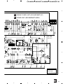
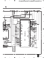
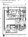
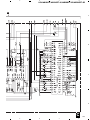
1
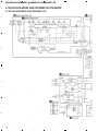
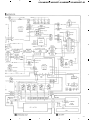
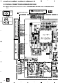
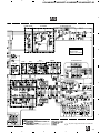
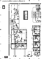
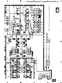
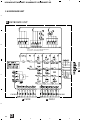
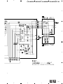
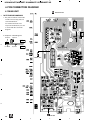
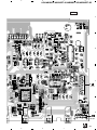
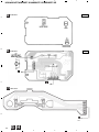
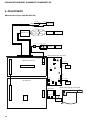
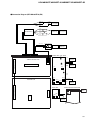
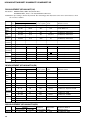
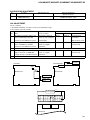
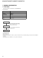
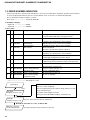
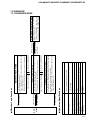
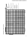
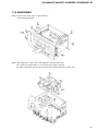
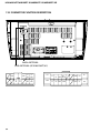
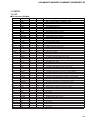
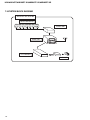
Service
Manual
ORDER NO.
CRT2393
ES300
AUDIO SYSTEM
HEAD UNIT
VEHICLE
LEXUS ES300
DESTINATION
PRODUCED AFTER
U.S.A.,CANADA August 1999
ID No.
P1715
TOYOTA PART No.
86120-33320
LEXUS ES300
MIDDLE EAST
P2724
86120-33241
Manufactured for TOYOTA
by PIONEER CORPORATION
August 1999
PIONEER MODEL No.
KEX-M8196ZT/UC
KEX-M8196ZT-91/UC
KEX-M8396ZT-02/ES
KEX-M8396ZT-92/ES
PUB. NO. CRT2393
Service
Manual
ORDER NO.
CRT2456
ES300
AUDIO SYSTEM
HEAD UNIT
VEHICLE
LEXUS ES300
DESTINATION
MIDDLE EAST
Manufactured for TOYOTA
by PIONEER CORPORATION
PRODUCED AFTER
January 2000
ID No.
P2726
TOYOTA PART No.
86120-33390
PIONEER MODEL No.
KEX-M8396ZT-03/ES
KEX-M8396ZT-93/ES
PUB. NO. CRT2456
KEX-M8396ZT-03,M8396ZT-93
NOTE:
- KEX-M8396ZT-93/ES is supplementary genuine part for a TOYOTA vehicle, and a Pioneer product for
recycling stock.
- Supplementary model is identical to the original except for the addition of following items.
Part No.
KEX-M8396ZT-93/ES
CEG1026
CHA2025
CHL4051
CHP1888,1889
Description
Polyethylene Bag
Carton
Contain Box
Protector
- This service manual should be used together with the following manual(s):
Model
Order No. Mech. Module Remarks
CX-529
CRT1507
KEX-M8396ZT-02/ES CRT2393
2L
Cassette Mech. Module:Mech.Description, Disassembly
EXPLODED VIEWS AND PARTS LIST
EXTERIOR(Page 4)
- EXTERIOR SECTION PARTS LIST
Mark No.
48
49
58
Description
Grille Unit
Door
Panel
Part No.
KEX-M8396ZT-02/ES KEX-M8396ZT-03/ES
CXB5281
CXB5860
CAT2126
CAT2163
CNS5175
CNS5954
PIONEER CORPORATION
4-1, Meguro 1-Chome, Meguro-ku, Tokyo 153-8654, Japan
PIONEER ELECTRONICS SERVICE INC. P.O.Box 1760, Long Beach, CA 90801-1760 U.S.A.
PIONEER ELECTRONIC [EUROPE] N.V. Haven 1087 Keetberglaan 1, 9120 Melsele, Belgium
PIONEER ELECTRONICS ASIACENTRE PTE.LTD. 253 Alexandra Road, #04-01, Singapore 159936
C PIONEER CORPORATION 1999
K-ZZS. DEC. 1999 Printed in Japan
KEX-M8196ZT,M8196ZT-91,M8396ZT-02,M8396ZT-92
KEX-M8396ZT-02/ES
KEX-M8196ZT/UC
P1715
P2721
ID No. P1715
ID No. P2724
NOTE:
- KEX-M8196ZT-91/UC and KEX-M8396ZT-92/ES are supplementary genuine part for a TOYOTA vehicle,
and a Pioneer product for recycling stock.
- Supplementary model is identical to the original except for the addition of following items.
Description
Polyethylene Bag
Carton
Contain Box
Protector
Part No.
KEX-M8196ZT-91/UC
CEG1026
CHA2025
CHL3842
CHP1888,1889
KEX-M8396ZT-92/ES
CEG1026
CHA2025
CHL3841
CHP1888,1889
- This service manual should be used together with the following manual(s):
Model
CX-529
Order No.
CRT1507
Mech. Module Remarks
2L
Cassette Mech. Module:Circuit Description, Mech.Description, Disassembly
- Dolby noise reduction manufactured under license from Dolby Laboratories Licensing Corporation.
"Dolby" and the double-D symbol are trademarks of Dolby Laboratories Licensing Corporation.
CONTENTS
1.
2.
3.
4.
5.
6.
2
SAFETY INFORMATION ............................................3
EXPLODED VIEWS AND PARTS LIST .......................4
BLOCK DIAGRAM AND SCHEMATIC DIAGRAM ...10
PCB CONNECTION DIAGRAM ................................28
ELECTRICAL PARTS LIST ........................................45
ADJUSTMENT..........................................................56
7. GENERAL INFORMATION .......................................60
7.1 TEST MODE ......................................................60
7.2 ERROR NUMBERS INDICATION......................62
7.3 DIAGNOSIS .......................................................63
7.3.1 DIAGNOSIS MODE .................................63
7.3.2 DISASSEMBLY ........................................67
7.3.3 CONNECTOR FUNCTION DESCRIPTION ..68
7.4 PARTS ................................................................69
7.4.1 IC ..............................................................69
7.4.2 DISPLAY...................................................71
7.5 SYSTEM BLOCK DIAGRAM .............................72
8. OPERATIONS AND SPECIFICATIONS.....................73
KEX-M8196ZT,M8196ZT-91,M8396ZT-02,M8396ZT-92
1. SAFETY INFORMATION
This service manual is intended for qualified service technicians; it is not meant for the casual do-it-yourselfer.
Qualified technicians have the necessary test equipment and tools, and have been trained to properly and safely repair
complex products such as those covered by this manual.
Improperly performed repairs can adversely affect the safety and reliability of the product and may void the warranty.
If you are not qualified to perform the repair of this product properly and safely; you should not risk trying to do so
and refer the repair to a qualified service technician.
3
KEX-M8196ZT,M8196ZT-91,M8396ZT-02,M8396ZT-92
2. EXPLODED VIEWS AND PARTS LIST
2.1 EXTERIOR
- KEX-M8196ZT/UC
4
KEX-M8196ZT,M8196ZT-91,M8396ZT-02,M8396ZT-92
NOTE:
- Parts marked by “*” are generally unavailable because they are not in our Master Spare Parts List.
- Screws adjacent to ∇ mark on the product are used for disassembly.
- EXTERIOR SECTION PARTS LIST
- KEX-M8196ZT/UC
Mark No. Description
1
2
3
4
5
Screw
Screw
Case
Insulator
Spacer
Part No.
BMZ26P050FMC
BMZ30P050FMC
CNB1980
CNM5987
CNM5293
Mark No. Description
Part No.
36
37
38
39
40
Button(TAPE)
Button(CD)
Holder
Holder
Holder
CAC6020
CAC6021
CNV5561
CNV5560
CNV3647
6
7
8
9
10
Main Unit
Chassis Unit
CWM6072
CXB3159
Cassette Mechanism Module EXK3240
Screw
IMS30P050FMC
MIC(MIC351)
CPM1011
41
42
43
44
45
Holder
LCD Unit
Keyboard Unit
Knob Unit
Spring
CNV3648
CWM6074
CWM6073
CXB3157
CBL-108
11
12
13
14
15
Screw
Screw(M3x5)
Connector
Connector(CN901)
Plug(CN902)
BMZ30P060FMC
CBA1409
CDE5764
CKM1311
CKM1221
46
47
48
49
50
Knob Unit
Spring
Grille Unit
Door
Spring
CXB3158
CBL-108
CXB3160
CAT1990
CBH1371
16
17
18
19
20
Connector(CN751)
Connector(CN401)
Connector(CN652,653)
Plug(CN701,702)
Antenna Jack(CN651)
CKS2826
CKS3578
CKS3009
CKS3156
CKX1024
51
52
53
54
55
Cushion
Earth Plate
Rubber
Rubber
Rubber
CNM6317
CNC8383
CNV5558
CNV5556
CNV5557
21
22
23
24
25
Holder(CN1)
Holder
Holder
Holder
•••••
CNC2218
CNC4981
CNC7716
CNC6058
56
57
58
59
60
Holder
Cushion
Panel
Screw
LCD
CNC6774
CNM6411
CNS5175
BPZ20P060FMC
CAW1528
26
27
28
29
30
FM/AM Tuner Unit
Screw
Button(UP,DOWN)
Button(EJECT)
Button(1,2)
CWE1523
BPZ26P100FMC
CAC5889
CAC6181
CAC6177
61
62
63
64
65
Connector(CN1905)
Holder
Connector(CN1901,1902)
Connector(CN1904)
IC(IC921)
CKS2757
CNV5559
CKS2666
CKS2757
PA2024A
31
32
33
34
35
Button(3,4)
Button(5,6)
Button(SCAN,P.SCAN)
Button(AM)
Button(FM1/2)
CAC6178
CAC6179
CAC6180
CAC6182
CAC6019
66 Transistor(Q958,959)
67 Volume(VR901-905)
68 Volume(VR1901)
2SB942
CCS1119
CCS1226
5
KEX-M8196ZT,M8196ZT-91,M8396ZT-02,M8396ZT-92
- KEX-M8396ZT-02/ES
6
KEX-M8196ZT,M8196ZT-91,M8396ZT-02,M8396ZT-92
- EXTERIOR SECTION PARTS LIST
- KEX-M8396ZT-02/ES
Mark No. Description
1
2
3
4
5
Screw
Screw
Case
Insulator
Spacer
Part No.
BMZ26P050FMC
BMZ30P050FMC
CNB1980
CNM5987
CNM5293
Mark No. Description
Part No.
36
37
38
39
40
Button(TAPE)
Button(CD)
Holder
Holder
Holder
CAC6020
CAC6021
CNV5561
CNV5560
CNV3647
6
7
8
9
10
CWM7069
CXB3159
Cassette Mechanism Module EXK3240
Screw
IMS30P050FMC
MIC(MIC351)
CPM1011
41
42
43
44
45
Holder
LCD Unit
Keyboard Unit
Knob Unit
Spring
CNV3648
CWM7071
CWM7070
CXB3157
CBL-108
11
12
13
14
15
Screw
Screw(M3x5)
Connector
Connector(CN901)
Plug(CN902)
BMZ30P060FMC
CBA1409
CDE5764
CKM1311
CKM1221
46
47
48
49
50
Knob Unit
Spring
Grille Unit
Door
Spring
CXB3158
CBL-108
CXB5281
CAT2126
CBH1371
16
17
18
19
20
Connector(CN751)
Connector(CN401)
Connector(CN652,653)
Plug(CN701,702)
Antenna Jack(CN651)
CKS2826
CKS3578
CKS3009
CKS3156
CKX1024
51
52
53
54
55
•••••
•••••
Rubber
Rubber
Rubber
CNV5558
CNV5556
CNV5557
21
22
23
24
25
Holder(CN1)
Holder
Holder
Holder
Shield Unit
CNC2218
CNC4981
CNC7716
CNC6058
CXB3865
56
57
58
59
60
Holder
Cushion
Panel
Screw
LCD
CNC6122
CNM6411
CNS5175
BPZ20P060FMC
CAW1528
26
27
28
29
30
Tuner Unit
Screw
Button(UP,DOWN)
Button(EJECT)
Button(1,2)
CWE1457
BPZ26P100FMC
CAC5889
CAC6181
CAC6177
61
62
63
64
65
Connector(CN1905)
Holder
Connector(CN1901,1902)
Connector(CN1904)
IC(IC921)
CKS2757
CNV5559
CKS2666
CKS2757
PA2024A
31
32
33
34
35
Button(3,4)
Button(5,6)
Button(SCAN,P.SCAN)
Button(AM/SW)
Button(FM)
CAC6178
CAC6179
CAC6180
CAC6183
CAC6022
66 Transistor(Q958,959)
67 Volume(VR901-905)
68 Volume(VR1901)
Main Unit
Chassis Unit
2SB942
CCS1119
CCS1226
7
KEX-M8196ZT,M8196ZT-91,M8396ZT-02,M8396ZT-92
2.2 CASSETTE MECHANISM MODULE
8
KEX-M8196ZT,M8196ZT-91,M8396ZT-02,M8396ZT-92
- CASSETTE MECHANISM MODULE SECTION PARTS LIST
Mark No. Description
Part No.
Mark No. Description
Part No.
Screw
Washer
Washer
Washer
Deck Unit
BSZ20P040FMC
CBF1037
CBF1038
CBG1003
EWM1008
46
47
48
49
50
Pinch Roller Unit
Reel Unit
Head Base Unit
Lever Unit
Gear Unit
EXA1473
EXA1484
EXA1434
EXA1438
EXA1436
6
7
8
9
10
Screw(M2×5)
Screw(M2×2.5)
Spring
Spring
Cushion
EBA1028
EBA1037
EBH1531
EBH1589
ENM1034
51
52
53
54
55
Frame Unit
Lever Unit
Head Assy(HD1)
Motor Unit(M1)
Washer
EXA1476
EXA1425
EXA1481
EXA1497
HBF-179
11
12
13
14
15
Spring
Spring
Spring
Spring
Spring
EBH1515
EBH1587
EBH1517
EBH1547
EBH1519
56
57
58
59
60
Screw
Resistor(R1)
Washer
Connector(CN251)
Connector(CN252)
BMZ20P022FMC
RD1/4HM181J
YE20FUC
CKS1711
CKS2127
16
17
18
19
20
Spring
Cord
Photo-reflector(EGN2, 3)
Photo-Interrupter(EGN1)
Roller
EBH1537
EDD1015
EGN1004
EGN1005
ENR1031
61
62
63
64
65
Connector(CN253)
•••••
Spring
Switch(S2)
Roller
CKS2129
EBH1545
ESG1004
ENR1023
21
22
23
24
25
Shaft
Roller
Arm
Arm
Guide
ELA1362
ELA1348
ENC1416
ENC1397
ENC1398
66
67
68
69
70
Cover
Cover
Spring
Washer
Washer
ENC1412
ENC1413
EBH1546
EBE1008
YE15FUC
26
27
28
29
30
Holder
Lever
Arm
Roller
Belt
ENC1417
ENC1449
ENC1401
ENR1027
ENT1027
71
72
73
74
75
Lever Unit
Spring
Screw(M2×2)
Capacitor(C1)
Bracket
EXA1424
EBL1026
CBA1250
CEA4R7M35LS2
ENC1472
31
32
33
34
35
Gear
Collar
Gear
Flywheel
Worm Gear
ENV1347
ENV1508
ENV1350
ENV1410
ENV1439
76 Inductor(L1)
77 Cushion
36
37
38
39
40
Worm Wheel
Gear
Lever
Arm
Gathering PCB
ENV1440
ENR1028
ENV1455
ENV1445
ENX1029
41
42
43
44
45
Gathering PCB
Switch(S1)
Motor Unit(M2)
Chassis Unit
Pinch Roller Unit
ENX1041
ESG1004
EXA1485
EXA1494
EXA1472
1
2
3
4
5
ETH0001
ENM1036
9
1
2
3
4
KEX-M8196ZT,M8196ZT-91,M8396ZT-02,M8396ZT-92
3. BLOCK DIAGRAM AND SCHEMATIC DIAGRAM
3.1 BLOCK DIAGRAM (KEX-M8196ZT/UC)
A
B
C
D
10
1
2
3
4
5
6
7
8
KEX-M8196ZT,M8196ZT-91,M8396ZT-02,M8396ZT-92
A
B
C
D
11
5
6
7
8
1
2
3
4
KEX-M8196ZT,M8196ZT-91,M8396ZT-02,M8396ZT-92
3.2 OVERALL CONNECTION DIAGRAM(GUIDE PAGE)
Note: When ordering service parts,be sure to refer to "EXPLODED VIEWS AND PARTS LIST"or"ELECTRICAL PARTS
LIST".
A-a
Large size
SCH diagram
A-b
A MOTHER PCB
CN1902
CN1901
CN702
CN701
Guide page
B
CN401
M8396ZT-02/ES ONLY
FM : -30dBs
AM : -30dBs
CN653
Detailed page
A-b
B TUNER CONTROL PCB
A-a
A-b
CN652
A-a
A-a
D KEYBOARD UNIT
A
CN751
F DECK UNIT
TAPE : -7.8dBs
(1kHz 0dB)
C
CN251
UC
R411 1R8K
R412 1R8K
ES
470
470
AVC-LAN
PEE
ASL
50K(W)
50K(W)
50K(W)
50K(W)
CD : +8.6dBs (1kHz 0dB)
D
50K(W)
CN902
12
A
1
2
3
4
6
5
8
7
KEX-M8196ZT,M8196ZT-91,M8396ZT-02,M8396ZT-92
A-b
LAMP DRIVE
A
8V REGURATOR
ILL DRIVE
Main Unit
Consists of
Mother PCB
Tuner Control PCB
TSW
AMP
MUTE
ANT
B
8V REGURATOR
M8396ZT-02/ES ONLY
RESET
FM : -15.9dBs
AM : -14.3dBs
TAPE : -4.5dBs
CD : +5.0dBs
5V REGURATOR
C
125µH
CN1
FM : -16.4dBs
AM : -14.9dBs
TAPE : -5.1dBs
CD : +4.4dBs
EARTH PLATE
CN901
E-VOL
M8396ZT-02/ES ONLY
D
: The power supply is shown with the marked box.
A
5
6
7
8
13
14
A-a
1
2
CN751
CN401
3
TAPE : -7.8dBs
(1kHz 0dB)
FM : -30dBs
AM : -30dBs
A MOTHER PCB
D
CN701
CN1901
M8396ZT-02/ES ONLY
CN702
CN1902
D KEYBOARD UNIT
RESET
4
3
2
1
2
3
B TUNER CONTROL PCB
UNIT
C
CN652
1
CN653
A
A-a A-b
KEX-M8196ZT,M8196ZT-91,M8396ZT-02,M8396ZT-92
4
B
4
5
6
ASL
ES
470
470
7
CN902
CD : +8.6dBs (1kHz 0dB)
A-a A-b
E-V
6
5
6
50K(W)
50K(W)
50K(W)
50K(W)
50K(W)
PEE
AVC-LAN
UC
R411 1R8K
R412 1R8K
FM : -15.9dBs
AM : -14.3dBs
TAPE : -4.5dBs
CD : +5.0dBs
5
KEX-M8196ZT,M8196ZT-91,M8396ZT-02,M8396ZT-92
7
8
A-a
8
15
A
B
C
D
CN251
F DECK UNI
16
A-b
1
2
3
ESET
TSW
AMP
ANT
M8396ZT-02/ES ONLY
MUTE
8V REGURATOR
3
4
3
Main Unit
Consists of
Mother PCB
Tuner Control PCB
8V REGURATOR
B
2
2
C
ILL DRIVE
1
1
LAMP DRIVE
A
A-a A-b
KEX-M8196ZT,M8196ZT-91,M8396ZT-02,M8396ZT-92
4
D
4
5
E-VOL
FM : -16.4dBs
AM : -14.9dBs
TAPE : -5.1dBs
CD : +4.4dBs
6
CN901
CN1
7
EARTH PLATE
125µH
7
A-a A-b
: The power supply is shown with the marked box.
M8396ZT-02/ES ONLY
5V REGURATOR
6
6
5
15.9dBs
14.3dBs
: -4.5dBs
5.0dBs
5
KEX-M8196ZT,M8196ZT-91,M8396ZT-02,M8396ZT-92
8
A-b
8
17
A
B
C
D
1
2
3
4
KEX-M8196ZT,M8196ZT-91,M8396ZT-02,M8396ZT-92
3.3 TUNER CONTROL PCB
A
B
TUNER CONTROL PCB
M8396ZT-02/ES ONLY
R651
SUB
ANTENNA
MAIN
ANTENNA
0R0
FM DIVERSITY
B
M8396ZT-02/ES
R661
C666
C680
ES
UC
33K
27K
R22 R022
R039 R015
M8196ZT/UC ONLY
C
***
***
***
FM : -30dBs
AM : -30dBs
CN653
CN652
D
A CN401
18
A CN401
B
1
2
3
4
6
5
8
7
KEX-M8196ZT,M8196ZT-91,M8396ZT-02,M8396ZT-92
A
FM/AM TUNER UNIT (KEX-M8196ZT/UC)
TUNER UNIT (KEX-M8396ZT-02/ES)
UC
C649 R033
C650 R033
C664 3900P
C665 3900P
***
***
***
M8396ZT-02/ES ONLY
ES
R022
R022
R018
R018
***
C
C
B
96ZT-02/ES ONLY
FM : -26dBs
AM : -16dBs
(400Hz 30%)
M8396ZT-02/ES ONLY
M8396ZT-02/ES ONLY
ES
UC
R512 4R7K 2R2K
R513 0R0 2R2K
***
***
C
Main Unit
Consists of
Mother PCB
Tuner Control PCB
B
5
6
7
8
D
19
1
2
3
4
KEX-M8196ZT,M8196ZT-91,M8396ZT-02,M8396ZT-92
3.4 FM/AM TUNER UNIT (KEX-M8196ZT/UC)
C
A
FM/AM TUNER UNIT
B
B
39K
56K
C
D
20
C
1
2
3
4
5
6
7
8
KEX-M8196ZT,M8196ZT-91,M8396ZT-02,M8396ZT-92
B
A
B
C
D
C
5
6
7
8
21
1
2
3
4
KEX-M8196ZT,M8196ZT-91,M8396ZT-02,M8396ZT-92
3.5 TUNER UNIT (KEX-M8396ZT-02/ES)
C
A
B
TUNER UNIT
B
KV1410-F1
KV1410-F1
KV1410-F1
C
D
22
C
1
2
3
4
5
6
7
8
KEX-M8196ZT,M8196ZT-91,M8396ZT-02,M8396ZT-92
B
A
B
C
D
C
5
6
7
8
23
1
2
3
4
KEX-M8196ZT,M8196ZT-91,M8396ZT-02,M8396ZT-92
3.6 KEYBOARD UNIT
A
KEYBOARD UNIT
15
15
15
15
D
B
E CN1905
LAMP
IL1903, 1904, 1911~1915 : CEL1464 (8V 60mA)
IL1906~1910 : CEL1492 (8V 60mA)
C
POWER
CN1904
VOLUME
CN1901
CN1902
A CN702
A CN701
D
24
D
1
2
3
4
2
1
3
4
KEX-M8196ZT,M8196ZT-91,M8396ZT-02,M8396ZT-92
3.7 LCD UNIT
A
E
LCD UNIT
D CN1904
B
CN1905
C
LCD DRIVER
LAMP
CEL1633 (8V 80mA)
D
E
1
2
3
4
25
1
2
3
4
KEX-M8196ZT,M8196ZT-91,M8396ZT-02,M8396ZT-92
3.8 CASSETTE MECHANISM MODULE
A
F
CN252
B
C
CN251
A
D
26
F
1
2
3
4
5
6
8
7
KEX-M8196ZT,M8196ZT-91,M8396ZT-02,M8396ZT-92
A
G
CN253
B
H
C
D
G H
5
6
7
8
27
1
2
3
4
KEX-M8196ZT,M8196ZT-91,M8396ZT-02,M8396ZT-92
4. PCB CONNECTION DIAGRAM
4.1 MAIN UNIT
A
A
MOTHER PCB
NOTE FOR PCB DIAGRAMS
1. The parts mounted on this PCB
include all necessary parts for
several destination.
For further information for
respective destinations, be sure
to check with the schematic
diagram.
2. Viewpoint of PCB diagrams
Capacitor
Connector
SIDE A
B
Chip Part
P.C.Board
SIDE B
B
CN652, 653
C
D
28
A
1
D
2
BASS
MID
CN1902
3
4
5
6
8
7
KEX-M8196ZT,M8196ZT-91,M8396ZT-02,M8396ZT-92
SIDE A
A
B
C
F
CN251
D
D
CN1901
D
TREBLE
5
FADER
BALANCE
6
7
A
8
29
1
2
3
4
KEX-M8196ZT,M8196ZT-91,M8396ZT-02,M8396ZT-92
A
MOTHER PCB
A
B
C
D
30
A
1
2
3
4
5
6
7
8
KEX-M8196ZT,M8196ZT-91,M8396ZT-02,M8396ZT-92
SIDE B
A
B
C
D
A
5
6
7
8
31
1
2
3
4
KEX-M8196ZT,M8196ZT-91,M8396ZT-02,M8396ZT-92
A
B
TUNER CONTROL PCB
B
C
A
D
32
CN401
B
1
2
3
4
5
6
8
7
KEX-M8196ZT,M8196ZT-91,M8396ZT-02,M8396ZT-92
A
SIDE A
B
C
C
D
B
5
6
7
8
33
1
2
3
4
KEX-M8196ZT,M8196ZT-91,M8396ZT-02,M8396ZT-92
A
B
TUNER CONTROL PCB
B
C
D
34
B
1
2
3
4
5
6
8
7
KEX-M8196ZT,M8196ZT-91,M8396ZT-02,M8396ZT-92
A
SIDE B
B
C
D
B
5
6
7
8
35
1
2
3
4
KEX-M8196ZT,M8196ZT-91,M8396ZT-02,M8396ZT-92
4.2 FM/AM TUNER UNIT (KEX-M8196ZT/UC)
SIDE A
28 14 15 16 17 18 19 20 21 22 23 24 25 26
A
8
9 10 11 12 13 27
B
B
C
1
2
3
4
5
FM/AM TUNER UNIT
6
7
C
D
36
C
1
2
3
4
2
1
4
3
KEX-M8196ZT,M8196ZT-91,M8396ZT-02,M8396ZT-92
SIDE B
A
B
C
FM/AM TUNER UNIT
C
D
1
2
3
C
4
37
1
2
3
4
KEX-M8196ZT,M8196ZT-91,M8396ZT-02,M8396ZT-92
4.3 TUNER UNIT (KEX-M8396ZT-02/ES)
SIDE A
A
B
B
C TUNER UNIT
C
D
38
C
1
2
3
4
2
1
4
3
KEX-M8196ZT,M8196ZT-91,M8396ZT-02,M8396ZT-92
SIDE B
A
B
C
TUNER UNIT
C
D
C
1
2
3
4
39
1
2
3
4
KEX-M8196ZT,M8196ZT-91,M8396ZT-02,M8396ZT-92
4.4 KEYBOARD UNIT
SIDE A
CD
SCAN
P.SCAN
AM (UC)
AM/SW (ES)
FM1/2 (UC)
FM (ES)
TAPE
A
4
5
6
B
EJECT
DOWN
D
D
UP
KEYBOARD UNIT
1
2
3
C
40
D
1
2
3
4
2
1
4
3
KEX-M8196ZT,M8196ZT-91,M8396ZT-02,M8396ZT-92
SIDE B
A
A
CN701
B
C
E
CN1905
CN702
D
KEYBOARD UNIT
A
D
D
1
2
3
4
41
1
2
3
4
KEX-M8196ZT,M8196ZT-91,M8396ZT-02,M8396ZT-92
4.5 LCD UNIT
SIDE B
SIDE A
A
B
E
E
LCD UNIT
CN1904
42
D
D
LCD UNIT
C
E
1
2
3
4
2
1
3
4
KEX-M8196ZT,M8196ZT-91,M8396ZT-02,M8396ZT-92
4.6 CASSETTE MECHANISM MODULE
G
A
A
CN751
B
F
DECK UNIT
C
D
F
1
2
3
4
43
1
2
3
4
KEX-M8196ZT,M8196ZT-91,M8396ZT-02,M8396ZT-92
A
B
G
PCB UNIT
SIDE A
G
PCB UNIT
SIDE B
F
C
H
H
REEL PCB
D
G
44
G H
1
2
3
4
KEX-M8196ZT,M8196ZT-91,M8396ZT-02,M8396ZT-92
5. ELECTRICAL PARTS LIST
NOTE:
- Parts whose parts numbers are omitted are subject to being not supplied.
- The part numbers shown below indicate chip components.
Chip Resistor
RS1/_S___J,RS1/__S___J
Chip Capacitor (except for CQS.....)
CKS....., CCS....., CSZS.....
=====Circuit Symbol and No.===Part Name
--- -------------------------------------------------
Part No.
-------------------------
Main Unit
Consists of
Mother PCB
Tuner Control PCB
CWM6072
(KEX-M8196ZT/UC)
A B Unit Number :: CWM6134
Unit Name
(KEX-M8396ZT-02/ES)
: Main Unit
=====Circuit Symbol and No.===Part Name
--- -------------------------------------------------
Part No.
-------------------------
Q
Q
Q
Q
Q
857
858
861
862
863
Transistor
Transistor
Transistor
Transistor
Transistor
2SB1260
2SA1162
IMD3A
DTC123YK
DTA114EK
Q
Q
Q
Q
Q
864
891
901
902
903
Transistor
Transistor
Chip Transistor
Chip Transistor
Chip Transistor
IMD3A
DTC144EK
2SC2712
2SC2712
2SC2712
Q
Q
Q
Q
Q
911
915
917
921
922
Transistor
Transistor
Transistor
Transistor
Transistor
2SC3651
DTA114TK
2SA1162
2SA1162
DTC114EK
Q
Q
Q
Q
Q
923
924
925
944
957
Transistor
Transistor
Transistor
Transistor
Chip Transistor
2SA1162
DTC114EK
IMD3A
DTA114EK
2SC2712
Q
Q
Q
Q
Q
958
959
960
961
962
Transistor
Transistor
Transistor
Chip Transistor
Transistor
2SB942
2SB942
2SD1767
2SC2712
2SA1162
D
D
D
D
D
301
302
303
471
472
Diode
Diode
Diode
Diode
Diode
1SS355
1SS355
1SS355
1SS355
1SS355
D
D
D
D
D
473
474
475
476
477
Diode
Diode
Diode
Diode
Diode
1SS355
1SS355
UDZS10(B)
UDZS10(B)
UDZS10(B)
D
D
D
D
D
478
503
652
655
680
Diode
Diode
Chip Diode
Diode (KEX-M8196ZT/UC)
Chip Diode
UDZS10(B)
MA8027(H)
MA151WK
1SV241
MA151WK
D
D
D
D
D
681
720
721
722
723
Chip Diode
Diode
Diode
Diode
Diode
MA151WK
1SS355
1SS355
1SS355
1SS355
D
D
D
D
D
724
725
831
841
863
Diode
Diode (KEX-M8396ZT-02/ES)
Diode
Diode (KEX-M8396ZT-02/ES)
Diode
1SS355
1SS355
UDZ20(B)
1SS355
1SS355
MISCELLANEOUS
IC
IC
IC
IC
IC
301
411
421
431
471
IC
IC
IC
IC
IC
PM2002
NJM2068MD
NJM2068MD
PMJ002A
TA2050F
IC
IC
IC
IC
IC
472
491
501
652
701
IC
IC
IC
IC (KEX-M8196ZT/UC)
IC
TA2050F
NJM2068MD
LC72146MQ
LA1061M
PE5009A
IC
IC
IC
Q
Q
821
881
921
301
351
IC
IC
IC
Transistor
Chip Transistor
S-80736AN-D0
CA0008AM
PA2024A
2SK209
2SC2712
Q
Q
Q
Q
Q
501
502
503
504
505
Transistor (KEX-M8396ZT-02/ES)
DTA114EK
Transistor (KEX-M8396ZT-02/ES)
DTC114EK
Chip Transistor (KEX-M8396ZT-02/ES)2SC2712
Transistor (KEX-M8396ZT-02/ES)
DTA114EK
Transistor (KEX-M8396ZT-02/ES)
DTC124EK
Q
Q
Q
Q
Q
506
511
512
661
662
Transistor
Chip Transistor
Transistor
Chip Transistor (KEX-M8196ZT/UC)
Transistor (KEX-M8196ZT/UC)
DTC144EK
2SC2712
2SK208
2SC2712
DTC143TK
Q
Q
Q
Q
Q
680
681
682
699
811
Chip Transistor
Chip Transistor
Chip Transistor
Transistor
Transistor
2SC2712
2SC2712
2SC2712
DTC144EK
DTC144EK
Q
Q
Q
Q
Q
831
832
841
842
851
Transistor
Transistor
Transistor (KEX-M8396ZT-02/ES)
Transistor (KEX-M8396ZT-02/ES)
Transistor
2SA1162
DTC144EK
2SA1162
DTC144EK
2SB1260
Q
Q
Q
Q
Q
852
853
854
855
856
Transistor
Transistor
Transistor
Transistor
Transistor
2SA1162
2SB1260
2SA1162
2SB1260
2SA1162
45
KEX-M8196ZT,M8196ZT-91,M8396ZT-02,M8396ZT-92
=====Circuit Symbol and No.===Part Name
--- -------------------------------------------------
Part No.
-------------------------
=====Circuit Symbol and No.===Part Name
--- -------------------------------------------------
Part No.
-------------------------
D
D
D
D
D
882
883
891
892
893
Diode
Diode
Diode
Diode
Diode
UDZ20(B)
UDZ20(B)
1SS355
1SS355
UDZ20(B)
R
R
R
R
R
306
307
308
309
310
RS1/10S472J
RS1/10S472J
RS1/10S684J
RS1/10S472J
RS1/10S682J
D
D
D
D
D
894
895
896
901
902
Diode
Diode
Diode
Diode
Diode
UDZ20(B)
1SS355
1SS355
GP30ML
1SS355
R
R
R
R
R
311
312
313
314
315
RS1/10S103J
RS1/10S154J
RS1/10S303J
RS1/10S472J
RS1/10S104J
D
D
D
D
D
903
904
905
906
911
Diode
Diode
Diode
Diode
Diode
1SS355
MA8075(H)
MA8075(H)
MA8075(H)
ERA15-02VH
R
R
R
R
R
316
317
318
351
352
RS1/10S102J
RS1/10S473J
RS1/10S912J
RS1/10S472J
RS1/10S471J
D
D
D
D
D
912
913
921
922
941
Diode
Diode
Diode
Diode
Diode
1SS355
UDZS5R6(B)
1SS355
1SS355
HZU4R3(B2)
R
R
R
R
R
353
354
355
356
357
RS1/10S683J
RS1/10S103J
RS1/10S222J
RS1/10S0R0J
RS1/10S102J
D
D
D
L
L
953
954
955
501
598
Diode
Diode
Diode
Inductor
Inductor
MA153
UDZS10(B)
UDZS8R2(B)
LCYA150K3225
LCYA100K3225
R
R
R
R
R
411
411
412
412
413
L
L
L
L
L
599
610
611
612
613
Inductor
Inductor (KEX-M8196ZT/UC)
Inductor (KEX-M8196ZT/UC)
Inductor (KEX-M8196ZT/UC)
Inductor (KEX-M8196ZT/UC)
LCYA100K3225
LCTBR33K3216
LCTBR33K3216
LCTB100K3216
LCTB100K3216
R
R
R
R
R
414
415
416
417
418
RS1/10S123J
RS1/10S123J
RS1/10S123J
RS1/10S183J
RS1/10S183J
L
L
L
L
L
614
615
616
617
618
Inductor (KEX-M8196ZT/UC)
Inductor (KEX-M8196ZT/UC)
Inductor (KEX-M8196ZT/UC)
Inductor (KEX-M8196ZT/UC)
Inductor (KEX-M8196ZT/UC)
LCTA561J4532
LCTBR33K3216
LCTBR33K3216
LCTBR33K3216
LCTB100K3216
R
R
R
R
R
421
422
423
424
425
RS1/10S473J
RS1/10S473J
RS1/10S473J
RS1/10S473J
RS1/10S473J
L
L
L
L
L
619
620
651
671
881
Inductor (KEX-M8196ZT/UC)
Inductor (KEX-M8196ZT/UC)
Inductor (KEX-M8196ZT/UC)
Inductor
Inductor
LCTB100K3216
LCTBR33K3216
LCYA150K3225
LCYA100K3225
LCTA100J3225
R
R
R
R
R
426
427
428
429
430
RS1/10S473J
RS1/10S473J
RS1/10S473J
RS1/10S103J
RS1/10S103J
L
L
L
L
L
901
921
922
923
924
Choke Coil 125µH
Inductor
Inductor
Inductor
Inductor
CTH1069
LCTA4R7J2520
LCTA4R7J2520
LCTA4R7J2520
LCTA4R7J2520
R
R
R
R
R
431
432
433
434
435
RS1/10S273J
RS1/10S273J
RS1/10S101J
RS1/10S101J
RS1/10S361J
L
L
X
X
VR
931
935
501
701
301
Inductor
Inductor
Crystal Resonator 4.5MHz
Ceramic Resonator 6.290MHz
Semi-fixed 10kΩ(B)
LCTA100J3225
LCTA100J3225
CSS1011
CSS1305
CCP1206
R
R
R
R
R
436
437
438
439
440
RS1/10S361J
RS1/10S471J
RS1/10S471J
RS1/10S181J
RS1/10S181J
VR
VR
VR
VR
VR
351
352
901
902
903
Semi-fixed 10kΩ(B)
Semi-fixed 10kΩ(B)
Volume 50kΩ(W)
Volume 50kΩ(W)
Volume 50kΩ(W)
CCP1206
CCP1206
CCS1119
CCS1119
CCS1119
R
R
R
R
R
441
442
443
471
472
RS1/10S153J
RS1/10S152J
RS1/10S123J
RS1/10S102J
RS1/10S102J
Volume 50kΩ(W)
CCS1119
Volume 50kΩ(W)
CCS1119
Microphone
CPM1011
FM/AM Tuner Unit (KEX-M8196ZT/UC) CWE1523
Tuner Unit (KEX-M8396ZT-02/ES) CWE1457
R
R
R
R
R
473
474
475
476
477
RS1/10S102J
RS1/10S102J
RS1/10S473J
RS1/10S473J
RS1/10S473J
R
R
R
R
R
478
479
480
481
482
RS1/10S473J
RS1/10S101J
RS1/10S101J
RS1/10S101J
RS1/10S101J
VR 904
VR 905
MIC 351
AR
AR
651
652
(KEX-M8196ZT/UC)
DSP-201M-A21F
DSP-201M-A21F
RESISTORS
R
R
R
R
R
46
301
302
303
304
305
RS1/10S103J
RS1/10S474J
RS1/10S472J
RS1/10S153J
RS1/10S153J
(KEX-M8196ZT/UC)
(KEX-M8396ZT-02/ES)
(KEX-M8196ZT/UC)
(KEX-M8396ZT-02/ES)
RS1/10S182J
RS1/10S471J
RS1/10S182J
RS1/10S471J
RS1/10S123J
KEX-M8196ZT,M8196ZT-91,M8396ZT-02,M8396ZT-92
=====Circuit Symbol and No.===Part Name
--- -------------------------------------------------
Part No.
-------------------------
=====Circuit Symbol and No.===Part Name
--- -------------------------------------------------
Part No.
-------------------------
R
R
R
R
R
491
492
493
494
495
RS1/10S103J
RS1/10S103J
RS1/10S103J
RS1/10S103J
RS1/10S103J
R
R
R
R
R
683
684
685
686
687
RS1/10S333J
RS1/10S222J
RS1/10S222J
RS1/10S0R0J
RS1/10S0R0J
R
R
R
R
R
496
497
498
501
502
RS1/10S103J
RAB4C473J
RS1/10S183J
RS1/10S473J
RAB4C681J
R
R
R
R
R
694
695
696
697
699
RS1/10S102J
RS1/10S103J
RS1/10S393J
RS1/10S102J
RS1/10S221J
R
R
R
R
R
506
507
508
510
511
(KEX-M8396ZT-02/ES)
(KEX-M8396ZT-02/ES)
(KEX-M8396ZT-02/ES)
(KEX-M8396ZT-02/ES)
RS1/10S473J
RS1/10S473J
RS1/10S222J
RS1/10S473J
RS1/10S473J
R
R
R
R
R
701
702
705
706
707
RS1/10S222J
RS1/10S222J
RS1/10S102J
RAB4C681J
RS1/10S223J
R
R
R
R
R
512
512
513
513
514
(KEX-M8196ZT/UC)
(KEX-M8396ZT-02/ES)
(KEX-M8196ZT/UC)
(KEX-M8396ZT-02/ES)
RS1/10S472J
RS1/10S222J
RS1/10S0R0J
RS1/10S222J
RS1/10S152J
R
R
R
R
R
708
709
710
711
712
RS1/10S473J
RS1/10S472J
RS1/10S472J
RS1/10S472J
RS1/10S103J
R
R
R
R
R
515
516
517
518
519
RS1/10S222J
RS1/10S102J
RS1/10S103J
RS1/16S821J
RS1/16S151J
R
R
R
R
R
713
714
715
716
717
RS1/10S103J
RS1/10S473J
RS1/10S473J
RS1/10S102J
RS1/10S102J
R
R
R
R
R
530
534
537
538
545
RS1/10S0R0J
RS1/10S102J
RS1/10S102J
RS1/10S0R0J
RS1/10S332J
R
R
R
R
R
718
719
720
721
725
RS1/10S473J
RS1/10S473J
RS1/10S102J
RAB4C102J
RS1/10S102J
R
R
R
R
R
546
548
570
571
572
(KEX-M8196ZT/UC)
(KEX-M8196ZT/UC)
(KEX-M8196ZT/UC)
RS1/10S473J
RS1/10S103J
RS1/10S471J
RS1/10S103J
RS1/10S103J
R
R
R
R
R
727
728
731
732
733
RAB4C102J
RAB4C473J
RAB4C102J
RS1/10S473J
RS1/10S473J
R
R
R
R
R
573
574
575
576
577
(KEX-M8196ZT/UC)
(KEX-M8196ZT/UC)
(KEX-M8196ZT/UC)
(KEX-M8196ZT/UC)
(KEX-M8196ZT/UC)
RS1/10S104J
RS1/10S103J
RS1/10S104J
RS1/10S182J
RS1/10S683J
R
R
R
R
R
734
735
736
737
738
RS1/10S473J
RS1/10S473J
RS1/10S102J
RS1/10S102J
RS1/10S102J
R
R
R
R
R
578
581
582
583
584
(KEX-M8196ZT/UC)
(KEX-M8196ZT/UC)
(KEX-M8196ZT/UC)
(KEX-M8196ZT/UC)
(KEX-M8196ZT/UC)
RS1/10S334J
RS1/10S104J
RS1/10S101J
RS1/10S101J
RS1/10S473J
R
R
R
R
R
739
740
741
743
744
RAB4C102J
RS1/10S473J
RS1/10S473J
RS1/10S681J
RS1/10S102J
R
R
R
R
R
585
586
587
633
634
(KEX-M8196ZT/UC)
(KEX-M8196ZT/UC)
(KEX-M8196ZT/UC)
RS1/10S473J
RS1/10S224J
RS1/10S391J
RS1/10S101J
RS1/10S102J
R
R
R
R
R
745
746
747
748
749
RS1/10S102J
RS1/10S102J
RS1/10S102J
RS1/10S102J
RS1/10S102J
R
R
R
R
R
649
650
651
659
660
RS1/10S272J
RS1/10S272J
RS1/10S0R0J
RS1/10S562J
RS1/10S562J
R
R
R
R
R
754
755
756
757
759
RS1/10S102J
RS1/10S102J
RS1/10S102J
RS1/10S102J
RS1/10S102J
R
R
R
R
R
661
661
662
674
675
RS1/10S333J
RS1/10S273J
RS1/10S822J
RS1/10S102J
RS1/10S102J
R
R
R
R
R
760
761
762
763
767
RS1/10S102J
RS1/10S473J
RA3C102J
RA3C473J
RS1/10S222J
R
R
R
R
R
678
679
680
681
682
RS1/10S333J
RS1/10S333J
RS1/10S103J
RS1/10S222J
RS1/10S333J
R
R
R
R
R
768
769
773
776
777
RS1/10S473J
RS1/10S222J
RS1/10S473J
RS1/10S102J
RS1/10S102J
(KEX-M8396ZT-02/ES)
(KEX-M8196ZT/UC)
(KEX-M8396ZT-02/ES)
(KEX-M8396ZT-02/ES)
47
KEX-M8196ZT,M8196ZT-91,M8396ZT-02,M8396ZT-92
=====Circuit Symbol and No.===Part Name
--- -------------------------------------------------
Part No.
-------------------------
=====Circuit Symbol and No.===Part Name
--- -------------------------------------------------
Part No.
-------------------------
R
R
R
R
R
778
779
780
811
821
RS1/10S222J
RS1/10S222J
RS1/10S222J
RS1/8S222J
RS1/10S104J
R
R
R
R
R
944
959
960
961
962
RS1/10S104J
RS1/10S222J
RS1/10S223J
RS1/4S101J
RS1/4S101J
R
R
R
R
R
831
832
833
834
835
RS1/10S103J
RS1/10S103J
RS1/10S473J
RS1/4S101J
RS1/4S101J
R
R
R
R
R
963
965
966
967
968
RS1/10S103J
RS1/10S223J
RS1/10S103J
RS1/10S103J
RS1/10S123J
R
R
R
R
R
841
842
843
844
845
RS1/10S103J
RS1/10S103J
RS1/10S473J
RS1/4S101J
RS1/4S101J
R
R
R
R
R
969
970
971
972
973
RS1/10S103J
RS1/10S103J
RS1/10S103J
RS1/4S821J
RS1/10S103J
R
R
R
R
R
851
852
853
854
855
RS1/10S2R2J
RS1/10S471J
RS1/10S2R2J
RS1/10S471J
RS1/10S2R2J
R
R
R
R
R
974
975
976
977
978
RS1/8S472J
RS1/4S2R2J
RS1/4S2R2J
RS1/4S2R2J
RS1/4S2R2J
R
R
R
R
R
856
857
858
861
862
RS1/10S471J
RS1/10S2R2J
RS1/10S471J
RS1/10S102J
RS1/10S103J
R
998
RS1/4S0R0J
R
R
R
R
R
863
864
865
866
867
RS1/10S102J
RS1/10S102J
RS1/10S103J
RS1/10S102J
RS1/10S103J
R
R
R
R
R
868
869
870
871
885
RS1/10S153J
RS1/10S153J
RS1/10S153J
RS1/10S153J
RS1/4S101J
R
R
R
R
R
886
887
891
892
893
RS1/4S101J
RS1PMF680J
RS1/4S221J
RS1/4S471J
RS1/4S221J
R
R
R
R
R
894
903
904
905
906
RS1/10S103J
RS1/10S104J
RS1/10S473J
RS1/8S472J
RS1/8S222J
R
R
R
R
R
907
908
909
910
911
RS1/10S104J
RS1/10S223J
RS1/8S472J
RS1/8S222J
RS1/10S104J
R
R
R
R
R
912
913
914
915
916
RS1/10S223J
RS1/4S100J
RS1/4S100J
RS1/8S4R7J
RS1/10S153J
R
R
R
R
R
917
918
921
922
923
RS1/10S222J
RS1/10S474J
RS1/10S473J
RS1/10S102J
RS1/10S103J
R
R
R
R
R
924
925
926
927
941
RS1/10S183J
RS1/10S103J
RS1/10S183J
RS1/10S102J
RS1/10S102J
48
(KEX-M8396ZT-02/ES)
(KEX-M8396ZT-02/ES)
(KEX-M8396ZT-02/ES)
(KEX-M8396ZT-02/ES)
(KEX-M8396ZT-02/ES)
CAPACITORS
C
C
C
C
C
301
302
303
304
305
CEJA470M10
CEJA470M10
CEJA330M10
CEAL6R8M35
CEJA220M10
C
C
C
C
C
306
307
308
309
310
CEJANP100M16
CKSQYB823K25
CEJANP100M16
CEJANP220M16
CEJAR68M50
C
C
C
C
C
311
312
313
314
315
CEJA100M16
CEJA470M10
CEJA100M16
CEJANP100M16
CEJA220M10
C
C
C
C
C
316
317
318
351
352
CEJA101M10
CEJA470M10
CKSQYB103K50
CEJAR68M50
CEJA470M10
C
C
C
C
C
411
412
413
414
417
CEJA100M16
CEJA100M16
CEJANP3R3M25
CEJANP3R3M25
CCSQCH390J50
C
C
C
C
C
418
419
421
422
425
CCSQCH390J50
CKSQYB103K50
CCSQCH150J50
CCSQCH150J50
CEJA4R7M35
C
C
C
C
C
426
427
428
429
431
CEJA4R7M35
CEJA4R7M35
CEJA4R7M35
CKSQYB103K50
CKSQYB272K50
C
C
C
C
C
432
433
434
435
436
CKSQYB272K50
CEJA100M16
CEJA100M16
CEJA100M16
CEJA100M16
KEX-M8196ZT,M8196ZT-91,M8396ZT-02,M8396ZT-92
=====Circuit Symbol and No.===Part Name
--- -------------------------------------------------
Part No.
-------------------------
=====Circuit Symbol and No.===Part Name
--- -------------------------------------------------
Part No.
-------------------------
C
C
C
C
C
437
438
439
440
441
CEJA2R2M50
CEJA2R2M50
CKSQYB152K50
CKSQYB152K50
CKSQYB682K50
C
C
C
C
C
510
511
512
513
514
CEASR47M50
CCH1165
CKSQYB103K50
CKSQYB472K50
CGCYX103K25
C
C
C
C
C
442
443
444
445
446
CKSQYB682K50
CKSQYB222K50
CKSQYB222K50
CKSQYB124K25
CKSQYB124K25
C
C
C
C
C
515
520
523
594
595
CKSQYB103K50
CKSQYB103K50
CKSQYB223K50
CKSQYB102K50
CKSQYB103K50
C
C
C
C
C
447
448
449
450
451
CKSQYB682K50
CKSQYB682K50
CEJANP2R2M35
CEJANP2R2M35
CKSQYB823K25
C
C
C
C
C
599
627
629
630
631
CKSQYB102K50
CKSQYB103K50
CKSQYB103K50
CEAS100M16
CKSQYB392K50
C
C
C
C
C
452
453
454
455
456
CKSQYB823K25
CCSQCH101J50
CCSQCH101J50
CEJA100M16
CEJA100M16
C
C
C
C
C
632
633
637
639
643
C
C
C
C
C
457
458
459
461
462
CKSQYB104K50
CKSQYB103K50
CKSQYB102K50
CEJA100M16
CKSQYB104K25
C
C
C
C
C
644
645
649
649
650
(KEX-M8396ZT-02/ES)
(KEX-M8196ZT/UC)
(KEX-M8396ZT-02/ES)
(KEX-M8196ZT/UC)
CKSQYB103K50
CKSQYB103K50
CKSQYB333K50
CKSQYB223K50
CKSQYB333K50
C
C
C
C
C
463
464
471
472
473
CEJA2R2M50
CEJA100M16
CEJANP3R3M25
CEJANP3R3M25
CEJANP3R3M25
C
C
C
C
C
650
651
652
653
654
(KEX-M8396ZT-02/ES)
(KEX-M8196ZT/UC)
(KEX-M8196ZT/UC)
(KEX-M8196ZT/UC)
(KEX-M8196ZT/UC)
CKSQYB223K50
CEAS100M16
CCSQCH220J50
CCSQCH150J50
CCSQCH390J50
C
C
C
C
C
474
475
476
477
478
CEJANP3R3M25
CEJANP3R3M25
CEJANP3R3M25
CKSQYB102K50
CKSQYB102K50
C
C
C
C
C
655
656
657
658
659
(KEX-M8196ZT/UC)
(KEX-M8196ZT/UC)
(KEX-M8196ZT/UC)
(KEX-M8196ZT/UC)
(KEX-M8196ZT/UC)
CCSQCH220J50
CKSQYB222K50
CKSQYB473K25
CKSQYB472K50
CEAS100M16
C
C
C
C
C
479
480
481
482
483
CEJA101M10
CEJA101M10
CEJANP3R3M25
CEJANP3R3M25
CEJA3R3M50
C
C
C
C
C
660
661
664
664
665
(KEX-M8196ZT/UC)
(KEX-M8196ZT/UC)
(KEX-M8196ZT/UC)
(KEX-M8396ZT-02/ES)
(KEX-M8196ZT/UC)
CKSQYB103K50
CKSQYB103K50
CKSQYB392K50
CKSQYB183K50
CKSQYB392K50
C
C
C
C
C
484
485
486
487
488
CEJA3R3M50
CEJA3R3M50
CEJA3R3M50
CKSQYB223K50
CKSQYB223K50
C
C
C
C
C
665
666
666
667
668
(KEX-M8396ZT-02/ES)
(KEX-M8196ZT/UC)
(KEX-M8396ZT-02/ES)
(KEX-M8196ZT/UC)
(KEX-M8396ZT-02/ES)
CKSQYB183K50
CKSQYB224K16
CKSQYB223K50
CKSQYB103K50
CKSQYB103K50
C
C
C
C
C
489
490
491
492
493
CKSQYB223K50
CKSQYB223K50
CEJA101M10
CKSQYB104K50
CKSQYB471K50
C
C
C
C
C
670
675
676
677
678
C
C
C
C
C
494
495
496
497
498
CKSQYB471K50
CKSQYB471K50
CKSQYB471K50
CEJA3R3M50
CCSQCH390J50
C
C
C
C
C
679
680
680
681
682
C
C
C
C
C
499
501
502
503
504
CKSQYB103K50
CCSQCH120J50
CKSQYB102K50
CKSQYB223K50
CKSQYB102K50
C
C
C
C
C
683
687
690
691
692
CEAS3R3M50
CEAS101M10
CKSQYB223K50
CKSQYB103K50
CKSQYB102K50
C
C
C
C
C
505
506
507
508
509
CCSRCH101J50
CCSRCH101J50
CCSQCH120J50
CEAS100M16
CKSQYB103K50
C
C
C
C
C
701
702
703
705
727
CKSQYB102K50
CKSQYB102K50
CKSQYB102K50
CKSQYB102K50
CKSYB102K50
(KEX-M8396ZT-02/ES)
(KEX-M8396ZT-02/ES)
4.7µF/16V
(KEX-M8196ZT/UC)
(KEX-M8196ZT/UC)
(KEX-M8196ZT/UC)
(KEX-M8196ZT/UC)
(KEX-M8196ZT/UC)
(KEX-M8196ZT/UC)
(KEX-M8196ZT/UC)
(KEX-M8396ZT-02/ES)
CKSQYB103K50
CKSQYB103K50
CEAS2R2M50
CCSQCH150J50
CKSQYB102K50
CKSQYB103K50
CKSQYB103K50
CEAS100M16
CKSQYB102K50
CEAS1R0M50
CEAS1R0M50
CKSQYB393K25
CKSQYB153K50
CKSQYB682K50
CEAS3R3M50
49
KEX-M8196ZT,M8196ZT-91,M8396ZT-02,M8396ZT-92
=====Circuit Symbol and No.===Part Name
--- -------------------------------------------------
Part No.
-------------------------
C
C
C
C
C
728
729
730
745
760
CKSYB102K50
CKSYB102K50
CKSYB102K50
CKSQYB103K50
CKSYB102K50
C
C
C
C
C
767
768
776
777
778
CKSYB102K50
CKSYB102K50
CKSQYB102K50
CKSQYB103K50
CKSQYB102K50
C
C
C
C
C
779
780
821
822
831
CKSQYB102K50
CKSQYB102K50
CKSYB102K50
CKSQYB103K50
CKSQYB103K50
C
C
C
C
C
841
851
853
855
857
C
C
C
C
C
881
882
883
884
884
C
C
C
C
C
885
885
894
901
902
C
C
C
C
C
903
904
905
906
907
C
C
C
C
C
907
911
912
913
914
C
C
C
C
C
915
916
917
921
922
C
C
C
C
C
923
924
925
926
927
CEHAQ1R0M50
CEHAQ470M10
CEHAQ470M10
CEHAQ470M10
CKSQYB102K50
C
C
C
C
C
931
932
933
941
942
CEJA100M16
CKSQYB473K25
CKSQYB102K50
CEJA101M10
CKSQYB223K50
C
C
C
C
C
944
945
955
956
960
CKSQYB103K50
CKSQYB102K50
CKSQYB102K50
CKSQYB102K50
CEHAQ220M50
C
C
C
C
961
962
963
999
50
(KEX-M8396ZT-02/ES)
(KEX-M8196ZT/UC)
(KEX-M8396ZT-02/ES)
(KEX-M8196ZT/UC)
(KEX-M8396ZT-02/ES)
2200µF/16V
(KEX-M8196ZT/UC)
(KEX-M8396ZT-02/ES)
470µF/16V
0.047F/5.5V
(KEX-M8396ZT-02/ES)
CKSQYB103K50
CKSQYB102K50
CKSQYB102K50
CKSQYB102K50
CKSQYB102K50
CKSQYB473K25
CCSQCH101J50
CCSQCH101J50
CKSQYB101K50
CCSQCH101J50
CKSQYB101K50
CCSQCH101J50
CKSQYB102K50
CCH1001
CKSQYB473K50
CEJA1R0M50
CKSQYB473K50
CEJA1R0M50
CKSQYB473K50
CKSQYB101K50
CCSQCH101J50
CCH1183
CEAS1R0M50
CKSQYB473K25
CKSQYB103K50
CEAS101M10
CCL1040
CCSQCH471J50
CKSQYB102K50
CEHAQ470M10
CEJA1R0M50
CEJA1R0M50
CKSQYB103K50
CKSQYB102K50
=====Circuit Symbol and No.===Part Name
--- -------------------------------------------------
Part No.
-------------------------
Number : CWE1523 (KEX-M8196ZT/UC)
Unit Name : FM/AM Tuner Unit
C Unit
MISCELLANEOUS
IC
IC
Q
Q
Q
1
2
1
3
5
IC
IC
Transistor
FET
Transistor
PA4026A
PA4024A
2SC2712
3SK263
2SK1067
Q
Q
Q
Q
D
31
151
201
202
3
Transistor
Transistor
FET
Transistor
Diode
2SC2712
DTC144EU
2SK291
2SC2712
1SV251
D
D
D
D
D
4
5
6
7
8
Diode
Diode
Diode
Diode
Diode
1SV250
KV1410-F1
MA157
KV1410-F1
KV1410-F1
D
D
D
D
D
9
10
201
202
231
Diode
Diode
Diode
Diode
Diode
KV1410-F1
1SV250
MA157
1SV251
SVC253
L
L
L
L
L
1
2
3
4
5
Inductor
Air-core Coil
Air-core Coil
Air-core Coil
Coil
LCTBR12K2125
CTC1152
CTC1152
CTC1151
CTC1147
L
L
L
L
L
6
40
51
52
201
Air-core Coil
Inductor
Ferri-Inductor
Coil
Ferri-Inductor
CTC1153
LCTBR15K1608
LAU150K
CTC1136
LAU4R7K
L
L
L
L
L
202
203
208
209
210
Ferri-Inductor
Inductor
Inductor
Ferri-Inductor
Coil
LAU330K
CTF1371
LAU390K
LAU680K
CTB1103
L
T
TC
TC
TC
231
31
1
2
3
Inductor
Coil
Capacitor
Capacitor
Capacitor
LAU3R3J
CTE1116
CCL1046
CCL1046
CCL1046
CF
CF
CF
CF
CF
25
51
52
53
230
Ceramic Filter
Ceramic Filter
Ceramic Filter
Ceramic Filter
Crystal Filter
CTF1290
CTF1290
CTF1144
CTF1145
CTF1262
CF
X
X
VR
VR
232
151
231
101
151
Ceramic Filter
Radiator 918.5Hz
Crystal Resonator 10.26MHz
Semi-fixed 15kΩ(B)
Semi-fixed 10kΩ(B)
CTF1348
CSS1365
CSS1111
CCP1230
CCP1229
VR
VR
154
156
Semi-fixed 150kΩ(B)
Semi-fixed 100kΩ(B)
CCP1236
CCP1235
RESISTORS
R
R
R
R
R
3
4
6
8
9
RS1/16S223J
RS1/16S101J
RS1/16S101J
RS1/16S332J
RS1/16S823J
KEX-M8196ZT,M8196ZT-91,M8396ZT-02,M8396ZT-92
=====Circuit Symbol and No.===Part Name
--- -------------------------------------------------
Part No.
-------------------------
=====Circuit Symbol and No.===Part Name
--- -------------------------------------------------
Part No.
-------------------------
R
R
R
R
R
10
11
12
15
16
RS1/16S223J
RS1/16S124J
RS1/16S474J
RS1/16S161J
RS1/16S104J
C
C
C
C
C
7
8
9
10
11
CKSQYB473K16
CKSQYB104K16
CKSRYB222K50
CEJA1R0M50
CCSRCH470J50
R
R
R
R
R
17
18
19
21
22
RS1/16S332J
RS1/16S332J
RS1/16S154J
RS1/16S332J
RS1/16S510J
C
C
C
C
C
12
13
15
17
18
CCSRCJ3R0C50
CKSRYB222K50
CCSRCJ3R0D50
CCSRCH120J50
CKSRYB103K25
R
R
R
R
R
24
25
26
31
32
RS1/16S101J
RS1/16S221J
RS1/16S102J
RS1/16S470J
RS1/16S912J
C
C
C
C
C
19
20
21
22
23
CCSRCH120J50
CKSRYB222K50
CEJA100M16
CCSRRH100D50
CCSRRH150J50
R
R
R
R
R
33
34
35
51
55
RS1/16S912J
RS1/16S331J
RS1/16S331J
RS1/16S331J
RS1/16S102J
C
C
C
C
C
24
30
31
32
33
CCSRCH471J50
CCSRRH201J50
CKSRYB103K25
CKSQYB473K16
CCSRCH220J50
R
R
R
R
R
56
61
62
103
104
RS1/16S823J
RS1/16S392J
RS1/16S273J
RS1/16S333J
RS1/16S334J
C
C
C
C
C
34
41
51
52
54
CCSRCH4R0D50
CKSQYB104K16
CKSRYB223K25
CKSRYB103K25
CCSRCH470J50
R
R
R
R
R
105
107
152
155
157
RS1/16S683J
RS1/16S222J
RS1/16S393J
RS1/16S393J
RS1/10S223J
C
C
C
C
C
55
56
57
58
59
CKSQYB223K25
CKSQYB104K16
CKSRYB472K50
CEJA330M10
CKSRYB103K25
R
R
R
R
R
160
161
162
163
164
RS1/16S222J
RS1/16S563J
RS1/16S225J
RS1/16S222J
RS1/16S823J
C
C
C
C
C
61
62
63
65
101
CCSRCH270J50
CKSRYB103K25
CEJAR22M50
CKSQYB104K16
CEJANP100M10
R
R
R
R
R
165
201
202
203
204
RS1/16S102J
RS1/16S103J
RS1/16S103J
RS1/16S225J
RS1/16S472J
C
C
C
C
C
102
103
104
105
106
CKSRYB182K50
CKSQYB682K50
CEJA2R2M50
CKSRYB103K25
CCSRCH151J50
R
R
R
R
R
205
206
207
208
214
RS1/16S471J
RS1/16S220J
RS1/16S101J
RS1/16S102J
RS1/16S563J
C
C
C
C
C
107
151
152
153
154
CKSRYB103K25
CKSRYB562K25
CKSQYB104K16
CEJA3R3M50
CKSQYB104K16
R
R
R
R
R
215
230
231
232
237
RS1/16S393J
RS1/16S0R0J
RS1/16S242J
RS1/16S473J
RS1/16S103J
C
C
C
C
C
157
158
159
160
161
CEJA3R3M50
CKSYB474K16
CEJA220M6R3
CKSQYB104K16
CKSQYB104K16
R
R
R
R
R
238
239
240
241
243
RS1/16S104J
RS1/16S104J
RS1/16S103J
RS1/16S202J
RS1/16S123J
C
C
C
C
C
162
163
165
201
202
CEJA3R3M50
CKSRYB102K50
CCSRCH100D50
CKSRYB103K25
CCSRCH100D50
R
R
R
R
R
244
246
247
248
250
RS1/16S103J
RS1/16S0R0J
RS1/10S303J
RS1/16S0R0J
RS1/16S0R0J
C
C
C
C
C
203
204
205
206
207
CKSRYB332K50
CKSQYB473K16
CKSQYB473K16
CKSRYB103K25
CCSRCH120J50
C
C
C
C
C
211
212
213
215
216
CCSRCH560J50
CEJA101M10
CKSRYB103K25
CCSRCH680J50
CCSRCH101J50
CAPACITORS
C
C
C
C
C
1
2
3
5
6
CCSRCH220J50
CKSRYB222K50
CCSRCH4R0D50
CKSRYB222K50
CKSQYB473K16
51
KEX-M8196ZT,M8196ZT-91,M8396ZT-02,M8396ZT-92
=====Circuit Symbol and No.===Part Name
--- -------------------------------------------------
Part No.
-------------------------
=====Circuit Symbol and No.===Part Name
--- -------------------------------------------------
Part No.
-------------------------
C
C
C
C
C
217
219
220
221
230
CEJA1R0M50
CKSRYB223K25
CKSRYB103K25
CKSRYB103K25
CKSQYB104K16
T
T
CF
CF
CF
31
231
25
51
52
Coil
Coil
Ceramic Filter
Ceramic Filter
Ceramic Filter
CTE1116
CTB1106
CTF1290
CTF1290
CTF1290
C
C
C
C
C
231
232
233
234
235
CCSRCH330J50
CCSRCH150J50
CKSRYB103K25
CEJA330M10
CKSRYB332K50
CF
CF
CF
X
X
53
230
232
151
231
Ceramic Filter
Crystal Filter
Ceramic Filter
Radiator 918.5Hz
Crystal Resonator 10.26MHz
CTF1290
CTF1262
CTF1348
CSS1365
CSS1111
C
C
C
C
C
236
237
239
240
241
CKSQYB473K16
CCSRTH180J50
CKSRYB103K25
CKSYB104K16
CKSQYB104K16
VR
VR
VR
VR
101
151
154
156
Semi-fixed 15kΩ(B)
Semi-fixed 10kΩ(B)
Semi-fixed 150kΩ(B)
Semi-fixed 68kΩ(B)
CCP1230
CCP1229
CCP1236
CCP1234
C
C
C
C
C
242
243
244
245
250
CEJAR47M50
CKSQYB334K16
CKSQYB473K16
CKSQYB103K25
CCSRCJ3R0C50
RESISTORS
Number : CWE1457 (KEX-M8396ZT-02/ES)
Unit Name : Tuner Unit
C Unit
MISCELLANEOUS
IC
IC
Q
Q
Q
1
2
1
3
31
IC
IC
Transistor
FET
Transistor
PA4026A
PA4024A
2SC2712
3SK263
2SC2712
Q
Q
Q
Q
Q
151
201
203
204
205
Transistor
Transistor
Transistor
Transistor
Transistor
DTC124EU
FC12
DTC124EU
DTC124EU
DTC124EU
Q
Q
D
D
D
206
231
3
4
5
Transistor
Transistor
Diode
Diode
Diode
2SC4116
2SC4116
1SV251
1SV250
KV1410-F1
D
D
D
D
D
6
7
8
201
202
Diode
Diode
Diode
Diode
Diode
MA157
KV1410-F1
KV1410-F1
MA157
1SV251
D
D
D
D
L
203
204
205
231
1
Diode
Diode
Diode
Diode
Inductor
MA141WA
MA110
MA110
KV1590
LCTBR12K2125
L
L
L
L
L
2
3
4
5
51
Coil
Inductor
Coil
Coil
Ferri-Inductor
CTC1145
LCTB4R7K2125
CTC1131
CTC1147
LAU150K
L
L
L
L
L
52
201
202
203
205
Coil
Inductor
Ferri-Inductor
Inductor
Inductor
CTC1136
LAU3R3K
LAU4R7K
CTF1371
LCTB3R3K2125
L
L
L
L
L
206
207
208
209
210
Inductor
Inductor
Inductor
Inductor
Coil
LCTB4R7K2125
LCTB120K2125
LAU180K
LAU120K
CTB1103
52
R
R
R
R
R
3
4
5
6
7
RS1/16S223J
RS1/16S101J
RS1/16S181J
RS1/16S101J
RS1/10S331J
R
R
R
R
R
8
9
10
11
12
RS1/16S473J
RS1/16S473J
RS1/16S223J
RS1/16S124J
RS1/16S474J
R
R
R
R
R
15
16
17
18
19
RS1/16S271J
RS1/16S104J
RS1/16S473J
RS1/16S473J
RS1/16S154J
R
R
R
R
R
27
31
32
33
34
RS1/16S0R0J
RS1/16S470J
RS1/16S912J
RS1/16S912J
RS1/16S331J
R
R
R
R
R
35
39
51
55
56
RS1/16S331J
RS1/16S0R0J
RS1/16S331J
RS1/16S102J
RS1/16S823J
R
R
R
R
R
61
62
103
104
105
RS1/16S392J
RS1/16S273J
RS1/16S333J
RS1/16S334J
RS1/16S683J
R
R
R
R
R
107
152
155
157
160
RS1/16S222J
RS1/16S393J
RS1/16S393J
RS1/10S203J
RS1/16S222J
R
R
R
R
R
161
162
163
165
201
RS1/16S563J
RS1/16S225J
RS1/16S222J
RS1/16S102J
RS1/16S471J
R
R
R
R
R
202
204
205
206
207
RS1/16S182J
RS1/16S103J
RS1/16S471J
RS1/16S220J
RS1/16S162J
R
R
R
R
R
208
210
211
212
213
RS1/16S0R0J
RS1/16S104J
RS1/16S103J
RS1/16S104J
RS1/16S103J
KEX-M8196ZT,M8196ZT-91,M8396ZT-02,M8396ZT-92
=====Circuit Symbol and No.===Part Name
--- -------------------------------------------------
Part No.
-------------------------
=====Circuit Symbol and No.===Part Name
--- -------------------------------------------------
Part No.
-------------------------
R
R
R
R
R
214
215
216
217
231
RS1/16S563J
RS1/16S473J
RS1/16S104J
RS1/16S393J
RS1/16S242J
C
C
C
C
C
103
104
105
106
107
CKSQYB682K50
CEJA2R2M50
CKSRYB103K25
CCSRCH151J50
CKSRYB103K25
R
R
R
R
R
232
234
235
237
238
RS1/16S473J
RS1/16S473J
RS1/16S472J
RS1/16S103J
RS1/16S104J
C
C
C
C
C
151
152
153
154
157
CKSRYB392K50
CKSQYB104K16
CEJA3R3M50
CKSQYB104K16
CEJA3R3M50
R
R
R
R
R
239
240
241
243
244
RS1/16S104J
RS1/16S472J
RS1/16S202J
RS1/16S123J
RS1/16S103J
C
C
C
C
C
158
159
160
161
162
CKSYB474K16
CEJA220M6R3
CKSQYB104K16
CKSQYB104K16
CEJA3R3M50
R
R
R
R
R
245
246
247
248
249
RS1/16S0R0J
RS1/16S0R0J
RS1/10S153J
RS1/16S473J
RS1/16S0R0J
C
C
C
C
C
163
165
201
202
203
CKSRYB102K50
CCSRCH100D50
CKSRYB103K25
CCSRCH180J50
CKSRYB332K50
C
C
C
C
C
204
205
206
207
208
CKSQYB473K16
CKSQYB473K16
CKSQYB103K25
CCSRCH120J50
CCSRCH180J50
C
C
C
C
C
209
210
211
212
213
CCSRCH470J50
CCSRCH470J50
CCSRCH270J50
CEJA101M10
CKSRYB103K25
C
C
C
C
C
215
216
217
218
219
CCSRCH470J50
CCSRCH100D50
CEJAR47M50
CKSRYB102K50
CCSRCH101J50
C
C
C
C
C
220
221
222
230
231
CKSRYB103K25
CKSRYB103K25
CCSRCH180J50
CKSQYB104K16
CCSRCH330J50
C
C
C
C
C
232
233
234
235
236
CCSRCH150J50
CKSRYB103K25
CEJA330M10
CKSRYB332K50
CKSQYB473K16
C
C
C
C
C
237
238
239
240
241
CCSRCH8R0D50
CCSRCH181J50
CKSRYB103K25
CKLSR104K16
CKSQYB104K16
C
C
C
C
C
242
243
244
245
250
CEJAR47M50
CEJAR33M50
CKSQYB473K16
CKSQYB103K25
CCSRCJ3R0C50
CAPACITORS
C
C
C
C
C
1
2
3
5
6
CCSRCH220J50
CKSRYB222K50
CCSRCH6R0D50
CKSRYB222K50
CKSQYB473K16
C
C
C
C
C
7
8
9
10
11
CKSQYB473K16
CKSQYB104K16
CCSRCJ3R0C50
CEJA1R0M50
CCSRCH470J50
C
C
C
C
C
12
13
14
15
16
CCSRCH820J50
CKSRYB222K50
CCSRCH4R0D50
CCSRCH7R0D50
CCSRCH120J50
C
C
C
C
C
17
18
19
20
21
CKSRYB222K50
CKSRYB103K25
CKSRYB222K50
CKSRYB222K50
CEJA100M16
C
C
C
C
C
22
23
24
30
31
CCSRRH100D50
CCSRRH120J50
CKSRYB103K25
CCSRRH201J50
CKSRYB103K25
C
C
C
C
C
32
33
35
36
40
CKSQYB473K16
CCSRCK2R0C50
CCSRCH270J50
CCSRCH120J50
CKSRYB222K50
C
C
C
C
C
41
51
52
54
55
CKSQYB104K16
CKSRYB223K25
CKSRYB103K25
CCSRCH470J50
CKSQYB223K25
C
C
C
C
C
56
57
58
59
61
CKSQYB104K16
CKSRYB472K50
CEJA330M10
CKSRYB103K25
CCSRCH270J50
MISCELLANEOUS
C
C
C
C
C
62
63
65
101
102
CKSRYB103K25
CEJAR22M50
CKSQYB104K16
CEJANP100M10
CKSRYB182K50
IL
IL
IL
IL
IL
D
Unit Number : CWM6073
(KEX-M8196ZT/UC)
: CWM7070
(KEX-M8396ZT-02/UC)
Unit Name : Keyboard Unit
1903
1904
1906
1907
1908
Lamp 8V 60mA
Lamp 8V 60mA
Lamp 8V 60mA
Lamp 8V 60mA
Lamp 8V 60mA
CEL1464
CEL1464
CEL1492
CEL1492
CEL1492
53
KEX-M8196ZT,M8196ZT-91,M8396ZT-02,M8396ZT-92
=====Circuit Symbol and No.===Part Name
--- -------------------------------------------------
Part No.
-------------------------
=====Circuit Symbol and No.===Part Name
--- -------------------------------------------------
Part No.
-------------------------
IL
IL
IL
IL
IL
Lamp 8V 60mA
Lamp 8V 60mA
Lamp 8V 60mA
Lamp 8V 60mA
Lamp 8V 60mA
CEL1492
CEL1492
CEL1464
CEL1464
CEL1464
R
R
R
R
R
278
281
282
283
284
RS1/16S104J
RS1/8S0R0J
RS1/8S0R0J
RS1/8S0R0J
RS1/8S0R0J
Lamp 8V 60mA
Lamp 8V 60mA
Volume 50kΩ(B)
CEL1464
CEL1464
CCS1226
R
R
R
R
R
285
286
287
288
289
RS1/16S0R0J
RS1/16S0R0J
RS1/16S0R0J
RS1/16S0R0J
RS1/16S0R0J
RS1/8S150J
RS1/4S150J
RS1/4S150J
RS1/8S150J
R
R
R
R
R
290
301
302
303
304
RS1/8S0R0J
RS1/16S223J
RS1/16S223J
RS1/16S561J
RS1/16S561J
R
R
R
R
R
321
322
351
352
353
RS1/8S223J
RS1/8S223J
RS1/16S102J
RS1/16S102J
RS1/16S102J
R
R
R
R
R
354
355
356
357
358
RS1/16S102J
RS1/10S274J
RS1/10S202J
RS1/10S472J
RS1/10S103J
R
R
R
R
R
359
360
361
373
374
RS1/10S103J
RS1/10S102J
RS1/10S622J
RS1/8S0R0J
RS1/8S0R0J
R
R
R
R
R
375
401
402
403
404
RS1/8S0R0J
RS1/16S273J
RS1/16S223J
RS1/16S274J
RS1/16S823J
R
405
RS1/16S274J
1909
1910
1911
1912
1913
IL 1914
IL 1915
VR 1901
RESISTORS
R
R
R
R
1901
1902
1903
1904
E
Unit Number : CWM6074
(KEX-M8196ZT/UC)
: CWM7071
(KEX-M8396ZT-02/ES)
Unit Name : LCD Unit
MISCELLANEOUS
IC 1902
IL 1901
IL 1902
IC
Lamp 8V 80mA
Lamp 8V 80mA
LCD
LC75821W
CEL1633
CEL1633
CAW1528
RESISTORS
R
R
R
R
R
1902
1904
1906
1908
1910
RS1/10S473J
RS1/10S102J
RS1/10S102J
RS1/10S102J
RS1/10S102J
CAPACITORS
C
C
C
C
F
1902
1904
1906
1908
CCSQCH681J50
CKSQYB103K50
CKSQYB473K25
CKSQYB102K50
CAPACITORS
Unit Number : EWM1008
Unit Name : Deck Unit
MISCELLANEOUS
IC
IC
Q
Q
Q
251
351
271
351
352
IC
IC
Transistor
Transistor
Transistor
HA12173-01
PA2020A
2SC4116
2SB1260
2SC4102
D
VR
VR
351
301
302
Diode
Semi-fixed 33kΩ(B)
Semi-fixed 33kΩ(B)
MA141K
CCP1130
CCP1130
RESISTORS
R
R
R
R
R
255
256
257
258
259
RS1/16S181J
RS1/16S181J
RS1/16S183J
RS1/16S183J
RS1/16S133J
R
R
R
R
R
260
261
262
271
272
RS1/16S133J
RS1/16S274J
RS1/16S274J
RS1/16S183J
RS1/8S223J
R
R
R
R
R
273
274
275
276
277
RS1/8S223J
RS1/8S103J
RS1/16S473J
RS1/16S104J
RS1/16S224J
54
C
C
C
C
C
251
252
253
254
255
CKSRYB391K50
CKSRYB391K50
CKSRYB391K50
CKSRYB391K50
CKSRYB103K25
C
C
C
C
C
256
271
272
301
302
CKSRYB103K25
CEV1R0M50
CKSQYB104K16
CKSYB474K16
CKSYB474K16
C
C
C
C
C
303
304
305
306
307
CKSRYB222K50
CKSRYB222K50
CKSRYB222K50
CKSRYB222K50
CKSRYB222K50
C
C
C
C
C
308
309
310
311
312
CKSRYB222K50
CKSQYB104K16
CKSQYB104K16
CKSQYB104K16
CKSQYB104K16
C
C
C
C
C
322
351
352
353
354
CEV100M16
CKSYB224K25
CKSQYB392K50
CKSQYB103K50
CKSQYB103K50
KEX-M8196ZT,M8196ZT-91,M8396ZT-02,M8396ZT-92
=====Circuit Symbol and No.===Part Name
--- -------------------------------------------------
Part No.
-------------------------
C
C
C
C
C
355
356
401
402
403
CKSYB104K50
CKSQYB103K50
CKSRYB182K50
CKSRYB822K25
CKSRYB333K16
C
404
CKSRYB471K50
Number :
Unit Name : PCB Unit
G Unit
L
S
S
EGN
R
1
1
2
1
1
Inductor
Switch(Load)
Switch(70µS)
Photo-Interruptor
ETH0001
ESG1004
ESG1004
EGN1005
RD1/4HM181J
Number :
Unit Name : Reel PCB
H Unit
EGN
EGN
2
3
Photo-Reflector
Photo-Reflector
EGN1004
EGN1004
Miscellaneous Parts List
M
M
HD
C
1
2
1
1
Motor Unit(Main)
Motor Unit(Sub)
Head Assy
EXA1497
EXA1485
EXA1481
CEA4R7M35LS2
55
KEX-M8196ZT,M8196ZT-91,M8396ZT-02,M8396ZT-92
6. ADJUSTMENT
- Connection Diagram (KEX-M8196ZT/UC)
BACK UP
+13.2V
ACC
GND
DC Regulated
Power Supply
GND
Lch +
Lch -
GM-8066ZT/UC
4Ω
Oscilloscope(1)
mV Meter(1)
Rch +
Rch -
Antenna Plug
4Ω
Dummy Antenna
50Ω(37.5Ω)
Stereo
Modulator
FM SSG
50Ω(75Ω)
FM/AM TUNER UNIT (TOP VIEW)
Main
Antenna Jack
TUNER CONTROL PCB
To MOTHER PCB
Pin26
TC1
TC2
Pin 19 (FMTV)
TC3
FM/AM TUNER UNIT
DC V
Meter(1)
Pin14
Pin28
L6
T31
L5
Pin27
Pin13
VR151
MOTHER PCB
VR156
VR154
FM/AM TUNER UNIT(BOTTOM VIEW)
L52
VR302(R)
Pin3
Pin2
R
L
VR301(L)
mV
Meter(2)
56
DC V
Meter(2)
Pin1
DECK UNIT
DECK UNIT
To TUNER CONTROL PCB
L52
IC701
Pin 6 (FMSD)
VR101
C63
Center
Meter
KEX-M8196ZT,M8196ZT-91,M8396ZT-02,M8396ZT-92
- Connection Diagram (KEX-M8396ZT-02/ES)
BACK UP
+13.2V
ACC
GND
DC Regulated
Power Supply
GND
Lch +
Lch -
GM-8066ZT/UC
4Ω
mV Meter(1)
Oscilloscope(1)
Rch +
Rch -
Antenna Plug
4Ω
Dummy Antenna
50Ω(37.5Ω)
FM SSG
Stereo
Modulator
50Ω(75Ω)
TUNER UNIT (TOP VIEW)
L2
Main
Antenna Jack
Pin26
DC V
Meter(3)
To MOTHER PCB
TUNER CONTROL PCB
Pin 18(AMTV)
L4
Pin 19(FMTV)
TUNER UNIT
DC V
Meter(1)
Pin 14
Pin 28
T231
T31
L5
Pin 27
Pin 13
VR151
MOTHER PCB
VR156
VR154
DC V
Meter(2)
Pin 1
TUNER UNIT(BOTTOM VIEW)
DECK UNIT
DECK UNIT
To TUNER CONTROL PCB
L52
IC701
Pin 6(SD)
VR101
L52
VR302(R)
Pin3
Pin2
R
L
Center
Meter
C63
VR301(L)
mV
Meter(2)
57
KEX-M8196ZT,M8196ZT-91,M8396ZT-02,M8396ZT-92
FM ADJUSTMENT (KEX-M8196ZT/UC)
Modulation
M:MONO MOD., 400Hz 30%(22.5kHz Dev.)
S1:STEREO MOD., 1kHz, L or R=30%(20.25kHz+7.5kHz Dev.)
NOTE:Before proceeding to further adjustments after switching power ON, let the tuner run for ten minutes to allow
the circuits to stabilize.
FM SSG
No.
TUN Volt 1
Center
1
Meter
IFT
1
ANT
1
Trimmer
RF Coil
1
RF
1
Trimmer
Separation 1
ARC
1
Frequency(MHz)
•••••
98.1 M
Displayed
Level(dBf)
•••••
65-85
107.9
98.1
Adjustment
Point
L5
L52
Frequency(MHz)
Adjustment Method
(Switch Position)
DC V Meter(1) : 6V
Center Meter : 0
98.1 M
98.1 M
5-15
5-15
98.1
98.1
T31
TC1,TC2
mV Meter(1) : Maximum
mV Meter(1) : Maximum
89.9 M
106.1 M
5-15
5-15
89.9
106.1
L6
TC3
mV Meter(1) : Maximum
mV Meter(1) : Maximum
Repeat steps RF Coil and RF Trimmer until the adjustment standards are satisfied.
98.1 S
65
98.1
VR101
mV Meter(1) : Maximum
98.1 S
38
98.1
VR154
mV Meter(1) : Separation 5dB
Separation
Interstation 1
98.1 M
65
98.1
Noise
2
98.1 M
-∞
98.1
Search
1
Sensitivity 2
3
mV Meter(1) : AdB
VR151
mV Meter(1) : A-20dB
98.1 M
33
98.1
VR156
DC V Meter(2) : more than 3.5V
98.1 M
32
98.1
VR156
DC V Meter(2) : 0
Repeat steps 1 and 2 until the adjustment standards are satisfied.
FM ADJUSTMENT (KEX-M8396ZT-02/ES)
FM SSG
No.
TUN Volt 1
Center
1
Meter
IFT
1
ANT
1
Coil
RF Coil
1
Separation 1
ARC
1
Frequency(MHz)
•••••
98.1 M
Displayed
Level(dBf)
•••••
65-85
108.0
98.1
Adjustment
Point
L5
L52
Frequency(MHz)
98.1 M
89.9 M
5-15
5-15
98.1
89.9
T31
L2
89.9 M
98.1 S
98.1 S
5-15
65
40
89.9
98.1
98.1
L4
VR101
VR154
98.1 M
65
98.1
98.1 M
-∞
98.1
Adjustment Method
(Switch Position)
DC V Meter(1) : 6.5V
Center Meter : 0
mV Meter(1) : Maximum
mV Meter(1) : Maximum
mV Meter(1) : Maximum
mV Meter(1) : Maximum
mV Meter(1) : Separation 5dB
Separation
Interstation 1
Noise
2
1
Sensitivity 2
3
Search
mV Meter(1) : AdB
VR151
mV Meter(1) : A-20dB
98.1 M
27
98.1
VR156
DC V Meter(2) : more than 3.5V
98.1 M
26
98.1
VR156
DC V Meter(2) : 0
Repeat steps 1 and 2 until the adjustment standards are satisfied.
SW2 ADJUSTMENT (KEX-M8396ZT-02/ES)
AM SSG
No.
TUN Volt 1
58
Frequency(MHz)
•••••
Displayed
Level(dBf)
•••••
Frequency(MHz)
21.975
Adjustment
Point
T231
Adjustment Method
(Switch Position)
DC V Meter(3) : 6.0V
KEX-M8196ZT,M8196ZT-91,M8396ZT-02,M8396ZT-92
DOLBY B/C NR ADJUSTMENT
No.
1
Test Tape
Adjustment Point
NCT-150
(400Hz,200nwb/m)
VR301(Lch),VR302(Rch)
Adjustment Method
(Switch Position)
mV Meter(2) : –8.24dBs+1.5dB,-0.5dB
(DOLBY NR Switch : OFF)
ASL ADJUSTMENT
Preset conditions
1. Set VR301 and VR351 around the center of the adjustable range.
2. Ground pins 3 and 16 of IC301.
Step Input
Output
No. (MIC)
(Pin 22 of IC301)
Adj.point
1
By using an oscillator, apply a sine
Observe the output at
VR351
wave of 7Hz/2.0mV to the MIC
Pin 22 on a DC voltmeter
terminal (+) via a 600-ohm resistor.
(pointer-type).
2
By using an oscillator, apply a sine
Observe the output at
VR301
wave of 7Hz/20mV to the MIC
Pin 22 on a digital
terminal (+) via a 600-ohm resistor.
multimeter.
3
Repeat Steps 1 and 2 until doth adjustments satisfy the specifications.
4
By using the jig(CAN-906,CAN-912), Observe the output at
VR351
apply a sine wave of 100dB-SPL
Pin 22 on a digital
voltage directly to the MIC terminal. multimeter.
5
End
Adjustment
Spec.
Conditions
1.8±0.3V
Pin 16:Ground
Pin 3:Open
Wait for 20 seconds.
5.2±0.1V
Pin 16:Ground
Pin 3:Ground
5.2±0.1V
Pin 16:Ground
Pin 3:Ground
Oscillator
BOTTOM VIEW
TOP VIEW
VR351
600Ω
MIC
22pin
MOTHER PCB
MOTHER PCB
VR301
DC volt meter
Digital multi
meter
DC Regulated
Power Supply
GND
13.2V
SLD
FL
FR
MUTE TEL
MUTE
AMPB
ILL+
BU
GND
RL
RR
BEEP
SGND
ANTB
ILL-
ACC
CN901
CN901
CN902
MOTHER PCB
59
KEX-M8196ZT,M8196ZT-91,M8396ZT-02,M8396ZT-92
7. GENERAL INFORMATION
7.1 TEST MODE
Test mode is mainly used adjustment of CDX-M8066ZT/WL.
a) CD multi-player
Function
SCAN
Power ON/OFF
TRK UP
FWD kick
TRK DOWN
REV kick
RDM
Tracking close
REV
Tracking open
RPT
Focus close
• Switching to test mode
Normal mode
Press the CD key three times,
while holding down the [1] and
[6] keys simultaneously.
Diagnosis mode
Press the TRK UP and CD keys
simultaneously.
CD test mode
• Canceling test mode
Switch the ACC off.
• SINGLE/10TRK/32TRK will continue to operate even after the key is released.Tracking closed the moment C-MOVE is
released.
• JUMP MODE resets to SINGLE as soon as power is switched off.
60
KEX-M8196ZT,M8196ZT-91,M8396ZT-02,M8396ZT-92
- Flow Chart
1
6
Press the CD key three times,
while holding down the [1] and
[6] keys simultaneously.
Diagnosis mode
Press the TRK UP and CD
keys simultaneously.
CD test mode
<Regulator OFF>
CD player select
CD
DISC
Display
Regulator ON
CD 6
DISC
Display
Normal focus close 00
*2
Normal display
S curve check 01
Focus gain
Focus EQ check 02
Track gain
TRACK
'
*3 100 TRK jump & carriage move
*4 SINGLE/4/10/32
<Regulator ON>
SCAN
*1
Tracking Close in a little while the keys are released
continuous even after key release
*1
TRACK
CD 6 0 -0'00
Power
OFF
SCAN
DISC
DOWN
RPT
<Close focus>
Focus mode
select
*1
DISC
Display
TRK
DOWN
TRK UP
Carriage shifted
outwards while
this key is pressed
TRACK
CD 6 11-1'11
Carriage shifted
inwards while
this key is pressed
Power
OFF
SCAN
DISC
DOWN
RDM
<Close tracking>
<Close tracking>
DISC
Display
example
Power
OFF
SCAN
RPT
TRK
DOWN
TRK UP
No AGC
TRACK
*2
CD 6 1 -0'50
Carriage move
or T. jump
TRK
TRK UP
DOWN
<Close spindle>
(Rough)
Carriage shifted
outwards while
this key is pressed
Carriage shifted
inwards while
this key is pressed
Carriage move
or T. jump
DISC
DOWN
RPT
RDM
REV
*3
AGC display
select
*4
Power
OFF
Single
SCAN
REV
C.MOVE
4TRK
10TRK
100TRK
32TRK
*2
AGC
Tracking open
Select T.jump mode
Tracking open
(in the case of continuous
jumping)
61
KEX-M8196ZT,M8196ZT-91,M8396ZT-02,M8396ZT-92
7.2. ERROR NUMBERS INDICATION
If the CD should fail to operate in CD multi player or if an error has taken place during the operation and resulted in
an error, the player will enter into the error mode. And the cause of such error is numerically indicated.
This is armed at assisting an analysis or repair.
Error mode ............................... Mode (A), Mode (B)
(1) Examples of Display
• Mode (A) ............................... ERR-X
• Mode (B) ............................... ERR-XX
(2) Error Codes
*1
*2
Classification
Description
Cause/Detail
1
10
ELECTRIC
Carriage home failure
Carriage doesn't move to or from the innermost position
11
ELECTRIC
Focus failure
12
ELECTRIC
SETUP failure
Spindle failed to lock or subcode unreadable
Subcode failure
tSpindle defective, defect, severe vibration
14
ELECTRIC
Mirror failure
17
ELECTRIC
Set up failure
Unrecorded CD-R
The disc is upside-down, defects, vibration
AGC protect failed
tHome switch failed and/or carriage immobile
Focus failed
tDefects, disc upside-down, severe vibration
tDefects, disc upside-down, severe vibration
30
ELECTRIC
Search time out
Failed to reach target address
tCarriage/tracking defective and/or defects
4
A0
SYSTEM
Power failure
Power overvoltage or short circuit detected
tSwitching transistor defective and/or power abnormal
3
50
MECHANISM
60
MECHANISM
An error upon ejection
An error while putting in
and out the tray
70 MECHANISM An error upon elevation
2
80 MECHANISM An error with an empty
magazine inserted
• *1 ........................................... Mode (A) error code
• *2 ........................................... Mode (B) error code
Nomal play
Error
Mode(A):
Displays an error code
Mode(B):
Displays an error code
MAG switch release time has time out
Elevation time out when eject
Tray in / out time has time out
Tray is caught when put in
Elevation time has time out
No disc is available
To obtain more information:
While error code is displayed:
1.Press the CD key three times, while holding down the (1) and
(6) keys simultaneously.
(The system enters Diagnosis mode.)
2.Then,press the TRK DOWN and 4keys simultaneously.
The error status of the product is maintained.
Mode(B):To cancel the error code, set ACC to OFF
Returns to normal
mode with ACC ON.
62
The system performs retry operation for the error.
4Return to LAN CHECK
4Return to LAN CHECK
The system displays historical operational errors
recorded for each physical address (for each device)
during normal operation in the past.
•Max. 6 Diagnostic codes for each physical address (for
each connected device)
Diagnosis Memory mode
5Go to Diagnosis Memory
The system displays the physical address of each
device connected to AVC-LAN.
•The device's own physical address is included.
LAN CHECK mode
3Go to System Check
CH6
CH2
CH5 (Press and hold for 1.7 seconds.)
TUNE +
TUNE -
4Return to LAN CHECK
5Go to Diagnosis Memory
6Memory Clear
•Page up
•Page down
CH1
ACC OFF/ON
CD key (Press and hold for 1.7 seconds.)
while holding down CH1 or CH6.
Press the CD key three times,
KEX-M8196ZT/UC, M8396ZT-02/ES
3Go to System Check
2End Diagnosis
System Check mode
The system runs a self-diagnosis and displays the
results (diagnostic codes).
•Max. 6 Diagnostic codes for each physical address (for
each connected device)
•Displays the current status (past errors not displayed)
Operation Specifications
1Go to Diagnosis
-
2End Diagnosis
2End Diagnosis
1Go to Diagnosis
2End Diagnosis
Flowchart and Functions
Normal
mode
-
Complete clearing
(automatic)
6Memory Clear
Diagnosis Memory Clear
The system clears Diagnosis
Memory (the codes).
•After completing clearing, the
system goes to LAN CHECK mode.
KEX-M8196ZT,M8196ZT-91,M8396ZT-02,M8396ZT-92
7.3 DIAGNOSIS
7.3.1 DIAGNOSIS MODE
63
64
1-F
0
1
6
1-F
0
1
5
1-F
0
1
4
1-7
9-F
8
0
1
3
1-F
0
1
2
1-8
A-F
8
0
1
1
1
1
A/C
computer
1
ATIS
decoder
GPS
receiver
0
1
1
1
0
Equalizer
0
Radio
0
Navigation ATIS
computer
0
M.DISP
computer
0
2
2
FM
multiplex
decoder
2
2
Cassette
2
FM
multiple
2
2
4
CD-CH
with
video
4
AV
machine
4
3
3
3
4
CD-CH
4
DSP
4
Radio/cas- CD-P
sette
without CH
controller
3
TV tuner
3
3
Physical Address Assignment
3
-
5
5
5
5
5
1DIN
-TV
5
6
MD-CH
6
6
CD-CH
6
6
EMV
6
7
7
7
7
7
CD-ROM
navigation
7
Body
computer
8
CD-ROM
-CH
8
H. W
AMP
8
MD-P
8
9
9
9
9
9
Audio
H/U
Audio
ECU
8
9
8
A
MD-ROM
-CH
A
A
MD-CH
A
A
A
C
B
B
B
B
B
C
C
C
DAT
C
C
Rear seat Rear
TV
control
SW
Display
with SW
B
D
D
D
D
D
D
E
E
E
DCC
E
E
MD-CH
commander
CD-CH
commander
E
F
F
F
TEL
ECU
F
F
F
—
123
1 : Controllers
2 : Video output devices
3 : Audio output devices
4 : Audio processing devices
5 : Information output devices
6 : Vehicle devices
1Device groups
The second device
connected is
an “audio H/U.”
Example: 2—190
Serial No. Physical address
1
Display
KEX-M8196ZT,M8196ZT-91,M8396ZT-02,M8396ZT-92
2
-
F
D/E
C
B
A
9
8
7
6
5
4
3
2
1
0
Microprocessor
error
ROM
error
RAM
error
ACC
error
MUTE
error
2
+B error
1
3
Common Diagnostic code
among devices
NO
ERR
1
0
Cassette
deck
error
5
TV tuner
error
7
8
9
CH
elevator
error
CD, CH
clamp
error
CH
tray error
CD, CH
EJT
failure
Dirt, scar
and upsidedown in
CD, CH
Detected
P.U temperature
in CD, CH
Detected
overcurrent in
CD, CH
r
r
MD, CH
CH
MD, CH
recording
function
error
r
MD, CH
r
MD, CH
r
MD, CH
r
MD, CH
DSP
error
LCD
error
CD deck MD deck Amplifier EQ error
or CD-CH or MD-CH error
error
error
6
Main
antenna
error
Sub
antenna
error
TV
antenna
error
Antenna
selector
error
Antenna
error
Switch
error
A
B
AUDIO
ECU
error
Diagnostic code specific to a particular device
AM tuner Cassette
deck EJT
error
failure
FM tuner Tape entanerror
gled in the
cassette
deck
Dirt in
cassette
deck
head
Broken
cassette
deck belt
4
Assignment of Diagnostic Codes
C
*1
E
No response
to Diagnosis
F
Diagnostic code for
communications
Communications
failure
No response
to periodical
communications
No response
to communications
D
No Diagnostic code assigned 00
<During System Check mode>
• KEX-M8196ZT/UC
• KEX-M8396ZT-02/ES
• KEX-M8196ZT/UC
• KEX-M8396ZT-02/ES
D1, D2, D4, FF, 50
<During Diagnosis Memory mode>
- Items corresponding each model
NOTES:
*1 Instruction to check for an error
in periodical communications is
interrupted.
The third content of Diagnosis is
"No response to periodical
communications."
D2
Diagnostic code
Serial No.
Example: 3
12
1
Display
KEX-M8196ZT,M8196ZT-91,M8396ZT-02,M8396ZT-92
65
66
Beep
• When changing to another mode
• When changing to another mode
1
Serial No.
Example:
1E0
Physical address
(CD commander)
—
1
Diagnostic code
—
1
360
Physical address (CD-CH)
—
—
———
The system changes as shown above, as this unit
does not include System Check.
00
• When there is no Diagnostic code after completion
of System Check
Displays a physical address.
The next lowest physical address
When there is no physical address:
1
1DIN-TV has recorded an error indicating there
is no response to periodical communications
in CD-CH.
Serial No.
Example:
Displays an auxiliary code
••Identifies the device involved in the error.
Max. 6 for each physical address
(no response to periodical
communications)
Serial No.
Example:
d2
Physical address (1DIN-TV)
Distinguishes from LAN-CHECK.
150
Displays a Diagnostic code.
••Identifies the type of error.
Example: H
Displays a physical address.
••Identifies the device.
• After completing System Check
Elapsed time (31 minutes)
1F
1
—
02
00
• When there is no Diagnostic data:
Displays a physical address.
Displays an auxiliary code. (Same as the left.)
Displays Diagnostic code. (Same as the left.)
Serial No. Elapsed time (2 minutes)
Example:
Displays a periodical communications
number.
••Displays the time when the error occurred.
Displays a physical address.
(Same as the left.)
• Displays the details of Diagnosis.
• The system displays a number from 00 to
FF (increases a digit every minute).
• When 256 minutes are reached, the system
returns to 00.
Example:
• Then, "Latest periodical communications
number" is displayed.
••Elapsed time at the current point is displayed.
Blinking "CODE" is displayed.
• The system beeps once every time
a physical address is displayed.
• The system beeps once every time
a physical address is displayed.
Blinking "SYS" is displayed.
• The system beeps three times
when changing to another mode.
• The system beeps three times
when changing to another mode.
• The system beeps three times
when starting up Diagnosis.
• The system displays the physical address of each
device connected to AVC-LAN in sequence from
the lowest address.
Diagnosis Memory mode
System Check mode
LAN-CHECK mode
Go to Diagnosis (Beep and Display)
Display
-
KEX-M8196ZT,M8196ZT-91,M8396ZT-02,M8396ZT-92
KEX-M8196ZT,M8196ZT-91,M8396ZT-02,M8396ZT-92
7.3.2 DISASSEMBLY
NOTE : Remove in the order of the circled numbers in
the disassembly diagram.
NOTE : The temperature of the screw on the right side of the rear panel rises.
• The cassette mechanism will not come off unless the grille is removed.
• The main volume knob may be removed easily if it is pulled off from the reverse side.
67
KEX-M8196ZT,M8196ZT-91,M8396ZT-02,M8396ZT-92
7.3.3 CONNECTOR FUNCTION DESCRIPTION
MAIN ANTENNA
SUB ANTENNA (KEX-M8196ZT/UC)
GND
MUTE
(-)
TX
68
(+)
TX
(+)
(+)
CDL
CDR
(-)
CDL
(-)
CDR
SLD
GND
BU
FL
FR
MUTE
TELMUTE
AMPB
ILL+
RL
RR
BEEP SGND
ANTB
ILL-
ACC
KEX-M8196ZT,M8196ZT-91,M8396ZT-02,M8396ZT-92
7.4 PARTS
7.4.1 IC
- Pin Functions (PE5009A)
Pin No.
1
2
3
4
5
6
7
8
9
10
11
12
13
14
15
16
17
18
19
20–25
26
27–30
31
32
33
34
35
36
37
38
39
40
41
42
43
44
45
46
47
48
49
50
51
52
53
54
55
56
57
58
59
60
61
Pin Name
BAL
FAD
ASL
AVSS
SDIN
PLCE
AVREF1
PLDI
PLDO
PLCK
TUNOFF
LDO
LCK
lcdbl
ill
LCE
linh
SYSPWR
TAPEPWR
kst0-5
NC
kd0-3
MSIN
f/R
VSS
PLAY
mtlin
LOAD
POS
RES
NES
SCO2
SCO1
CMO
staby
b/C
PEE
NROUT
VCK
VDT
VST
ANTB
AMP
NC
swdvdd
FM/am
IPPWR
IPDO
IPDI
NC
SYSMUTE
reset
NC
I/O
Format
I
O
C
I
O
O
O
O
O
O
O
O
O
O
O
O
C
C
C
C
C
C
C
C
C
C
C
C
I
I
O
C
O
I
I
I
I
I
O
O
O
O
O
O
O
O
O
O
O
O
C
C
C
C
C
C
C
C
C
C
C
C
C
O
O
O
O
I
C
C
C
C
O
I
C
Function and Operation
A/D converter input from BALANCE volume
A/D converter input from FADER volume
A/D converter input from ASL noise detection
A/D converter ground potential
Tuner SD detect input
Chip select output for PLL IC
(D/A converter reference voltage)
Serial data input from PLL IC
Serial data output for PLL IC
Serial clock output for PLL IC
Tuner power control output
Serial data output for LCD driver
Serial clock output for LCD driver
LCD back light output
ILL output
Chip select output for LCD driver
Inhibit output for LCD driver
System power control output
Tape power output
Key strobe output
Not used
Key return input
Cassette mechanism MS sense input
Cassette mechanism head forward/reverse select output
Grand potential
Tape MS filter output
Cassette mechanism metal tape detect input
Loading motor sense input
Cassette mechanism position sense input
Cassette mechanism reverse end sense input
Cassette mechanism normal end sense input
Cassette mechanism sub motor control output 2
Cassette mechanism sub motor control output 1
Cassette mechanism capstan motor control output
Cassette mechanism driver stand-by control output
Cassette mechanism dolbyNR B/C select output
PEE sound output
Cassette mechanism noise reduction output
Clock output for electronic volume
Data output for electronic volume
Strobe pulse output for electronic volume
Antenna power supply control output
Amp power supply control output
Not used
Switched VDD output
FM/AM select output
IE-BUS driver power output
IE-BUS driver data output
IE-BUS driver data input
Not used
System mute output
System reset input
Not used
69
KEX-M8196ZT,M8196ZT-91,M8396ZT-02,M8396ZT-92
Pin No.
62
63
64
65,66
67
68
69
70
71
72
73
74
75
76
77
78
79
80
Pin Name
asens
isens
bsens
NC
eject
VDD
X2
X1
IC
NC
TEST
AVDD
AVREF0
SL
VOL
BAS
MID
TRE
*PE5009A
80
I/O
I
I
I
Format
I
I
61
1
60
Function and Operation
ACC power sense input
Illumination sense input
Back up power sense input
Not used
Eject key input
Power supply
Crystal oscillator connection pin
Crystal oscillator connection pin
Connect to GND
Not used
Chip test mode detect input
A/D converter analog power supply (VDD)
(A/D converter reference voltage input)
Tuner signal level input
A/D converter input from POWER-VOL volume
A/D converter input from BASS volume
A/D converter input from MID volume
A/D converter input from TREBLE volume
IC's marked by* are MOS type.
Be careful in handling them because they are very
liable to be damaged by electrostatic induction.
Format
C
20
41
21
PA4026A
70
40
Meaning
C MOS
KEX-M8196ZT,M8196ZT-91,M8396ZT-02,M8396ZT-92
7.4.2 DISPLAY
COMMON
SEGMENT
- CAW1528
71
KEX-M8196ZT,M8196ZT-91,M8396ZT-02,M8396ZT-92
7.5 SYSTEM BLOCK DIAGRAM
AUDIO SYSTEM
SEVEN SPEAKERS
FR TW FL TW RR
RL WF
AUDIO AMP
HEAD UNIT
CD CHANGER
MUSIC CD
72
KEX-M8196ZT,M8196ZT-91,M8396ZT-02,M8396ZT-92
8. OPERATIONS AND SPECIFICATIONS
8.1 OPERATIONS (KEX-M8196ZT/UC)
- RADIO
PRESET RECALL
PRESET CH.MEMORY
SCAN
PRESET
SCAN
AM
VOLUME,
POWER ON/OFF
UP
P1715
MANUAL,
SEEK
TUNING
DOWN
FADER
BASS
MID
TREBLE
BALANCE
FAST
FORWARD
BLANK
SKIP
FM
- TAPE
DOLBY NR
DIRECTION CHANGE
REWIND
MUSIC
REPEAT
SCAN
VOLUME,
POWER ON/OFF
TAPE EJECT
UP
P1715
AUTOMATIC
PROGRAM
SEARCH
DOWN
FADER
BASS
MID
TREBLE
BALANCE
TAPE
73
KEX-M8196ZT,M8196ZT-91,M8396ZT-02,M8396ZT-92
- CD
DISC NUMBER
SEARCH
DOWN UP
FAST
FORWARD
REWIND
RANDOM
PLAY
TRACK
REPEAT
DISC SCAN,
TRACK SCAN
VOLUME,
POWER ON/OFF
UP
P1715
TRACK
NUMBER
SEARCH
DOWN
FADER
BASS
MID
TREBLE
BALANCE
CD
8.2 SPECIFICATIONS
General
Power source ...........................13.2 V (10.5 V -16.0 V allowable)
Grounding system..................................................Negative type
Dimensions ..........250 ± 0.5 (W) × 114 ± 0.5 (H) × 163.9 (D) mm
Weight ..................................................................................1.7 kg
Tape player
Tape .....................................Compact cassette tape (C -30 - C90)
Tape speed ........4.76 cm / sec. (+0.14 cm / sec., -0.05 cm / sec.)
Wow and flutter ......................................Less than 0.2%(WRMS)
Fast forward/rewind time.................Less than 120sec. for C -60
Stereo separation...............................................More than 30 dB
Signal-to-noise ratio ..........................................More than 41 dB
FM tuner
Frequency range (KEX-M8196ZT/UC) ............87.75 - 107.9 MHz
(KEX-M8396ZT-02/ES) .............87.5 - 108.0 MHz
Signal-to-noise ratio .............................More than 48 dB(stereo)
Distortion ...........................Less than 3.0%(60 dBf, 1kHz, stereo)
Stereo separation ......................More than 25 dB (60 dBf, 1kHz)
AM tuner
Frequency range (KEX-M8196ZT/UC) .................530 - 1,710 kHz
(KEX-M8396ZT-02/ES)................531 - 1,602 kHz
Usable sensitivity (KEX-M8196ZT/UC) 27dBµ ± 5dB (S/N:20dB)
(KEX-M8396ZT-02/ES) 29dBµ ± 5dB (S/N:20dB)
Selectivity.............................................More than 50 dB (±9 kHz)
Signal-to-noise ratio...........................More than 44 dB (74 dBµ)
Distortion................................................Less than 1.0% (74 dBµ)
PIONEER CORPORATION
4-1, Meguro 1-Chome, Meguro-ku, Tokyo 153-8654, Japan
PIONEER ELECTRONICS SERVICE INC. P.O.Box 1760, Long Beach, CA 90801-1760 U.S.A.
PIONEER ELECTRONIC [EUROPE] N.V. Haven 1087 Keetberglaan 1, 9120 Melsele, Belgium
PIONEER ELECTRONICS ASIACENTRE PTE.LTD. 253 Alexandra Road, #04-01, Singapore 159936
C PIONEER CORPORATION 1999
K-ZZY. JULY 1999 Printed in Japan