1
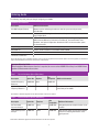
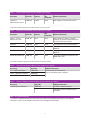
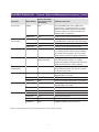
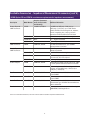
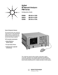
Agilent 4396B RF Network/
Spectrum/Impedance Analyzer
Configuration Guide
Ordering Guide
The following steps will guide you through configuring your 4396B.
Standard Furnished Item
Description
Additional Information
N to BNC adapter (50 ohm)
Adapter used for calibrating the reference level for spectrum analyzer mode;
PN 1250-0780
BNC cable
Cable used for calibrating the reference level for spectrum analyzer mode; 24 inch
long, PN 8120-1839
CD-ROM Manual
Contains Task Reference, User’s Guide, Function Reference, Programming Guide,
GPIB Command Reference, Performance Test Manual, Instrument BASIC User’s
Handbook, and Option 010 Operation Handbook in PDF. See documentation option
for printed manuals.
Sample Program Disk
Contains sample programs in two disks (3.5 inch).
INTUILINK CD
Contains Intuilink software for the 4294A/4395A/4396B.
Power Cable
Certificate of Calibration
Note: The following are not furnished: Printed copies of manuals, keyboard and test fixture. Refer to Accessory Option, Documentation Option and Available Accessories for the selection of these items.
Important Selection Guide
When Impedance Measurement function is required, be sure to select 4396B-010 at Step 3 and 43961A from
Impedance Measurement Accessories.
Step 1. Choose Hardware Option (Mandatory)
Description
Option No.
Requires
Not
Compatible
Standard Frequency
Reference
4396B-800
None
4396B-1D5
High Stability
Frequency Reference
4396B-1D5
None
4396B-800
Additional Information
This option improves the frequency accuracy
and stability of the 4396B.
Note: Refer to Hardware Upgrade for retrofit information on the above options.
Step 2. Choose Hardware Option (Mandatory)
Description
Option No.
Requires
Not
Compatible
No Time-Gated
Spectrum Analysis
4396B-706
None
4396B-1D6
Time-gated spectrum analysis function is not
installed.
Time-Gated Spectrum
Analysis
4396B-1D6
None
4396B-706
Adds the time-gated spectrum measurement
function for analyzing intermittent / burst
signal spectrum.
Note: Refer to Hardware Upgrade for retrofit information on the above options.
Additional Information
Step 3. Choose Software Option (If not required, go to Step 4)
Description
Option No.
Requires
Not
Compatible
Additional Information
Impedance
Measurement Function
4396B-010
43961A
None
Adds impedance measurement function.
Note: Refer to Software Upgrade for retrofit information on the above option.
Step 4. Choose Accessory Option (If not required, go to Step 5)
Description
Option No.
Requires
Not
Compatible
50 ohm – 75 ohm
Minimum Loss Pad
4396B-1D7
None
None
Adds minimum loss pad for converting
impedance of spectrum measurement input
port into 75 ohms from 50 ohms.
Keyboard
4396B-810
None
None
PS/2 keyboard for using Instrument Basic
Rackmount Kit
4396B-1CM
None
None
Can not be installable simultaneously with
4396B-1CP
Front Handle Kit
4396B-1CN
None
None
Can not be installable simultaneously with
4396B-1CP
Handle/Rack Mount Kit
4396B-1CP
None
None
Can not be installable simultaneously with
4396B-1CM or 1CN
Additional Information
Note: Refer to Hardware Upgrade for retrofit information on the above options.
Step 5. Choose Documentation Option (If not required, go to Step 6)
Description
Option No.
Additional Information
U.S. - English Localization
4396B-ABA
Japan - Japanese Localization
4396B-ABJ
Printed manuals are not furnished.
Order documentation option if required.
Service Manual
4396B-0BW
Step 6. Choose Calibration Certificate Option (If not required, go to Step 7)
Description
Option No.
Additional Information
17025 Compliant Calibration
4396B-1A7
ISO 17025 compliant calibration
–
ANSI Z540 compliant calibration option is
unavailable
Step 7. Choose Warranty Plan
1 year Return-to-Agilent Warranty and Service Plan are standard. For extended warranty options and additional
information, contact your local Agilent sales office or visit the Agilent home website.
Hardware Upgrade
Upgrade
Model No.
or Equivalent
Part Number
Customer
Installable
Requires
(Instrument
must already
include the
following)
Not
Compatible
Additional
Information
Option No.
Description
4396B-1D5
High Stability Frequency
Reference
4396V-1D5
No
None
None
Installable at
service center
only
4396B-1D6
Time-Gated Spectrum
Analysis
4396V-1D6
No
None
None
Installable at
service center
only
4396B-1D7
50 ohm – 75 ohm
Minimum Loss Pad
11852B-004
Yes
None
None
4396B-810
Keyboard
1150-7970
Yes
None
None
4396B-1CM
Rackmount Kit
5063-9216
Yes
None
4396B-1CP
4396B-1CN
Front Handle Kit
5063-9229
Yes
None
4396B-1CP
4396B-1CP
Handle/Rack Mount Kit
5188-4430
Yes
None
4396B-1CM
4396B-1CN
Note: For details of the upgrade information, refer to product homepage on the Agilent home website.
Software Upgrade
Upgrade
Model No.
or Equivalent
Part Number
Customer
Installable
Requires
(Instrument
must already
include the
following)
Not
Compatible
Additional
Information
None
(The 43961A
Impedance
Test Kit is
required)
None
See Available
Accessories for
additional information on the
43961A Impedance Test Kit.
Yes
None
None
Adds printed
copy of English
manual for
4396B-010
Yes
None
None
Adds printed
copy of Japanese manual for
4396B-010
Option No.
Description
4396B-010
Impedance
Measurement Function
4396V-010
Yes
U.S. - English
Localization
4396V-ABA
Japan - Japanese
Localization
4396V-ABJ
Note: For firmware update and upgrade information, refer to product page on the Agilent home website.
Available Accessories - Network Measurement Accessories
Description
Model Number
Requires (Instrument
must already include
the following)
50 ohm S-Parameter
Test Set
87511A
None
100 kHz to 500 MHz. Interconnect cable, RF connection cables and Operation and Service Manual are
furnished. Choose mandatory option 800 or 001.
87511A-800
None
7 mm test port
87511A-001
None
Type-N test port
87511A-1A7
None
ISO 17025 compliant calibration
87511A-907
None
Front handle kit
87511A-908
None
Rackmount kit
87511A-909
None
Handle and Rackmount kit
87511A-910
None
Extra operation manual
87511B
None
100 kHz to 500 MHz; Type-N test port. Interconnect
cable, RF connection cables and Operation and
Service Manual are furnished.
87511B-1A7
None
ISO 17025 compliant calibration
87511B-907
None
Front handle kit
87511B-908
None
Rackmount kit
87511B-909
None
Handle and Rackmount kit
87511B-910
None
Extra operation manual
85046A
None
300 kHz to 3 GHz; 7 mm test port. Interconnect
cable, type-N connection cables and Operation and
Service Manual are furnished. Choose mandatory
option 001 or 009.
85046A-001
None
Solid state switch
85046A-009
None
Mechanical test port transfer switch
85046A-UK6
None
Commercial Cal Certificate with test data
85046A-908
None
Rackmount kit
85046A-910
None
Additional copy of manual, English
85046A-913
None
Handle and Rackmount kit
85046A-ABJ
None
Japan – Japanese localization
85046B
None
300 kHz to 2 GHz; Type-N test port. Interconnect
cable, type-N connection cables and Operation and
Service Manual are furnished. Choose mandatory
option 001 or 009.
85046B-001
None
Solid state switch
85046B-009
None
Mechanical test port transfer switch
85046B-UK6
None
Commercial Cal Certificate with test data
85046B-908
None
Rackmount kit
85046B-913
None
Handle and Rackmount kit
85046B-ABJ
None
Japan – Japanese localization
75 ohm S-Parameter
Test Set
50 ohm S-Parameter
Test Set
75 ohm S-Parameter
Test Set
Additional Information
Available Accessories – Network Measurement Accessories (continued)
Description
Model Number
Requires (Instrument
must already include
the following)
50 ohm
Transmission/
Reflection Test Kit
87512A
None
50 ohm (DC to 2 GHz), type-N connectors,
Operation and Service Manual is furnished.
75 ohm
Transmission/
Reflection Test Kit
87512B
None
75 ohm (DC to 2 GHz), type-N connectors,
Operation and Service Manual is furnished.
50 ohm 2-Way
Power Splitter
11667A
None
DC to 18 GHz; type-N connectors. Operation and
Service Manual is furnished.
50 ohm RF Bridge
86205A
None
300 kHz to 6 GHz; type-N connectors. Operation
and Service Manual is furnished
75 ohm RF Bridge
86207A
None
300 kHz to 3 GHz; type-N connectors. Operation
and Service Manual is furnished.
Additional Information
Note: For more detailed information, refer to RF and Microwave Test Accessories Catalog.
Available Accessories – Network/Spectrum Measurement Accessories
Description
Model Number
Requires (Instrument
must already include
the following)
50 ohm
Accessory Kit
11853A
None
Accessory kit 50 ohm; contains type-N Short
terminations and barrels required for test setups.
Operation and Service manual is furnished
50 ohm
Accessory Kit
11854A
None
Accessory kit 50 ohm; Contains type-N to BNC
adapters and type-N Short termination required
for test setups. Operation and Service manual is
furnished.
75 ohm Cable Set
11857B
None
Cable set 75 ohm, type-N, 61 cm long. Operation
and Service manual is furnished.
11857B-201
None
Phase matched.
11857B-B24
None
Delete phase match requirement
11857D
None
Cable set 50 ohm, 7mm, 61 cm long. Operation and
Service manual is furnished.
11857D-201
None
Phase matched.
11857D-B24
None
Delete phase match requirement
50 ohm Cable N6314A
None
Cable 50 ohm, type-N (male) to type-N (male), 61 cm.
User’s Guide is furnished.
50 ohm Cable
N6315A
None
Cable 50 ohm, type-N (male) to type-N (female), 61 cm.
User’s Guide is furnished.
50 ohm Cable Set
Additional Information
Note: For more detailed information, refer to RF and Microwave Test Accessories Catalog.
Available Accessories – Network/Spectrum Measurement Accessories (cont’d.)
Description
Model Number
Requires (Instrument
must already include
the following)
Active Probe
41800A
None
5 Hz to 500 MHz active probe, 100 kilo-ohms
(probe alone) / 1 mega-ohm (with 10:1 or 100:1
divider). Probe to BNC adapter, hook tip adapter,
slip-on tip adapter, 10:1 and 100:1 dividers and
Operation Note are furnished.
41800A-UK6
None
Commercial Cal Certificate with test data
41802A
None
5 Hz to 100 MHz 1 Mega-ohm input adapter;
Compatible with oscilloscope probes (designated).
41802A-ABA
None
U.S. - English Localization
41802A-UK6
None
Commercial Cal Certificate with test data
Probe
85024A
None
300 kHz to 3 GHz high frequency probe for incircuit measurement. Probe tip to type-N Adapter,
10:1 divider, hook tip adapter, slip-on tip adapter,
leads and User’s and Service Guide are furnished.
Differential Probe
1141A
None
(1142A is required)
DC to 200 MHz differential probe; 1 mega-ohm.
10x/100x attenuator adapters, AC coupling
adapter, mini-grabbers, leads and User and Service
Guide are furnished. The 1142A is required.
Probe Control and
Power Module
1142A
None
Probe control and power module for the 1141A
Active Differential Probe. User and Service Guide
is common to the 1141A.
Close Field Probe
11940A
None
30 MHz to 1 GHz close field probe, hand held,
Operation Note is furnished
11941A-001
None
Rotary joint attachment
11940A-003
None
Do not include RG223 dbl-shielded cable/adapters
11941A
None
9 kHz to 30 MHz close field probe, hand held,
Operation Note is furnished.
11941A-001
None
Rotary joint attachment
11941A-003
None
Do not include RG223 dbl-shielded cable/adapters
11945A
None
Close field probe set. Operation Note is furnished.
11945A-001
None
Rotary joint attachment
11945A-003
None
Do not include RG223 dbl-shielded cable/adapters
11945A-E51
None
11909A Preamplifier with carrying case
1 Mega-ohm
Input Adapter
Close Field Probe
Close Field Probe Set
Additional Information
Note: For more detailed information, refer to RF and Microwave Test Accessories Catalog.
Available Accessories – Impedance Measurement Accessories
(4396B Option 010 and 43961A are minimum requirements for impedance measurements)
Description
Model Number
Requires (Instrument
must already include
the following)
Impedance Test Kit
43961A
4396B-010
Impedance test kit; contains impedance test
adapter, N (m)-N (m) cable, Open/Short/Load
terminations, carrying case and Notice.
Parallel Electrode
SMD Test Fixture
16196A
4396B-010, 43961A
For 1608 (mm) / 0603 (inch) SMD up to 3 GHz
16196A-710
None
Adds magnifying lens and tweezers
16196A-ABA
None
U.S. – English localization
16196A-ABJ
None
Japan – Japanese localization
16196B
4396B-010, 43961A
For 1005 (mm) / 0402 (inch) SMD up to 3 GHz
16196B-710
None
Adds magnifying lens and tweezers
16196B-ABA
None
U.S – English localization
16196B-ABJ
None
Japan – Japanese localization
16196C
4396B-010, 43961A
For 0603 (mm) / 0201 (inch) SMD up to 3 GHz
16196C-710
None
Adds magnifying lens and tweezers
16196C-ABA
None
U.S. – English localization
16196C-ABJ
None
Japan – Japanese localization
16196D
4396B-010, 43961A
For 0402 (mm) / 01005 (inch) SMD up to 3 GHz
16196D
None
Adds magnifying lens and tweezers
16196D
None
U.S – English localization
16196D
None
Japan – Japanese localization
16194A
4396B-010, 43961A
For SMD and leaded device up to 2 GHz,
Temperature range: -55°C to +200°C.
50 Ω working standard resistors, wrench, tweezers
and Operation and Service Manual are furnished.
16194A-010
None
Adds EIA/EIAJ size shorting bar set
16194A-701
None
Adds shorting bar set; (1 x 1 x 2.4, 1.6 x 2.4 x 2, 3.2
x 2.4 x 2.4, 4.5 x 2.4 x 2.4) mm
Parallel Electrode
SMD Test Fixture
Parallel Electrode
SMD Test Fixture
Parallel Electrode
SMD Test Fixture
High Temperature
Test Fixture
Additional Information
Note: For more detailed information, refer to RF and Microwave Test Accessories Catalog.
Available Accessories – Impedance Measurement Accessories (cont’d.)
(4396B Option 010 and 43961A are minimum requirements for impedance measurements)
Description
Model Number
Requires (Instrument
must already include
the following)
Bottom Electrode
SMD Test Fixture
16197A
4396B-010, 43961A
For SMD from 1005 (mm) / 0402 (inch) to
3225 (mm) / 1210 (inch); up to 3 GHz. Device
guides, EIA/EIAJ size shorting bar set, tweezers,
wrench, magnifying lens, carrying case and
Operation and Service Manual are furnished.
16197A-001
None
Adds 0603 (mm) / 0201 (inch) device guide
16197A-ABA
None
U.S. – English localization
16197A-ABJ
None
Japan – Japanese localization
SMD Test Fixture
16092A
4396B-010, 43961A
For SMD and leaded device up to 500 MHz.
Operation Note is furnished.
Parallel Electrode
SMD Test Fixture
16192A
4396B-010, 43961A
For SMD up to 2 GHz. Operation and Service
Manual is furnished.
16192A-010
None
Adds EIA/EIAJ size shorting bar set
16192A-701
None
Adds Shorting bar set; (1 x 1 x 2.4, 1.6 x 2.4 x 2,
3.2 x 2.4 x 2.4, 4.5 x 2.4 x 2.4) mm
16192A-710
None
Adds magnifying lens and tweezers
16200B
4396B-010, 43961A
External DC bias adapter; 5 A max or 40 V max, 1 MHz
to 1 GHz. Operation and Service Manual is furnished.
16200B-001
None
Adds shorting bars and 51 Ω working standard
resistors set; from 0603 (mm) / 0201 (inch) to
3216 (mm) / 1206 (inch)
Test Fixture
16093-65003
4396B-010, 43961A
Equivalent to previous 16093A; for leaded device
up to 250 MHz
Test Fixture
16093-65004
4396B-010, 43961A
Equivalent to previous 16093B; for leaded device
up to 125 MHz
Probe Test Fixture
16094-65000
4396B-010, 43961A
Equivalent to previous 16094A; for in-circuit
measurement up to 125 MHz. Recommended test
cable is 8120-4779.
Test Cable
8120-4779
4396B-010, 43961A
7-mm connector cable recommended for using
16094-65000; Cable length 60 cm.
DC Bias Adapter
Additional Information
Note: For more detailed information, refer to Accessories Selection Guide for Impedance Measurements.
Available Accessories – Calibration kit
Description
Model Number
Requires (Instrument
must already include
the following)
50 ohm Calibration kit
85031B
None
Calibration kit 50 ohm; Contains 7mm Open/Short,
50 ohm Load terminations, Operation and Service
Manual.
85031B-1A7
None
ISO 17025 compliant calibration
85031B-A6J
None
ANSI Z540 compliant calibration
85031B-UK6
None
Commercial Cal Certificate with test data
85032F
None
Calibration kit 50 ohm; Contains type-N Open,
Short, 50 ohm Load terminations, Operation and
Service Manual.
85032F-100
None
Adds Type-N 50 ohm female to female adapter
85032F-200
None
Adds Type-N 50 ohm male to male adapter
85032F-300
None
Adds Type-N 50 ohm female to male adapter
85032F-500
None
Adds four 7mm to type-N 50 ohm adapter
85032F-1A7
None
ISO 17025 compliant calibration
85032F-A6J
None
ANSI Z540 compliant calibration
85032F-UK6
None
Commercial Cal Certificate with test data
85033E
None
Calibration kit 50 ohm; Contains 3.5mm Open,
Short and 50 ohm Load terminations, OSL holder,
Operation and Service Manual.
85033E-100
None
Adds 3.5mm female to female adapter
85033E-200
None
Adds 3.5mm male to male adapter
85033E-300
None
Adds 3.5mm female to male adapter
85033E-400
None
Adds four 3.5mm to type-N adapters
85033E-500
None
Adds four 3.5mm to 7mm adapters
85033E-1A7
None
ISO 17025 compliant calibration
85033E-A6J
None
ANSI Z540 compliant calibration
85033E-UK6
None
Commercial cal. Certificate with test data
85036B
None
Calibration kit 75 ohm; Contains type-N Open,
Short, 50 ohm Load terminations, type-N adapters,
Operation and Service Manual.
85036B-1A7
None
ISO 17025 compliant calibration
85036B-A6J
None
ANSI Z540 compliant calibration
85036B-UK6
None
Commercial Cal Certificate with test data
50 ohm Calibration kit
50 ohm Calibration kit
75 ohm Calibration kit
Additional Information
Note: For more detailed information, refer to RF and Microwave Test Accessories Catalog.
10
11
www.agilent.com
Literature Resource
For more information on Agilent Technologies’ products, applications
or services, please contact your local Agilent office. The
complete list is available at:
Title
Publication
Number
4396B Data Sheet
5965-6311E
www.agilent.com/find/contactus
LCR Meters, Impedance Analyzers
and Test Fixtures Selection Guide
5952-1430E
Accessories Selection Guide For
Impedance Measurements
5965-4792E
Americas
Canada
Latin America
United States
(877) 894-4414
305 269 7500
(800) 829-4444
Impedance Measurement Handbook
5950-3000
RF and Microwave Test Accessories
Catalog
5968-4314EN
Asia Pacific
Australia China
Hong Kong India Japan
Korea
Malaysia Singapore Taiwan
Thailand 1 800 629 485
800 810 0189
800 938 693
1 800 112 929
0120 (421) 345
080 769 0800
1 800 888 848
1 800 375 8100
0800 047 866
1 800 226 008
Note: More literature is available on the Agilent home website.
Web Resource
Have access to the following website to acquire the
latest news, product and support information,
application literature and more.
www.agilent.com/find/impedance
Remove all doubt
Our repair and calibration services will get your equipment
back to you, performing like new, when promised. You will
get full value out of your Agilent equipment throughout
its lifetime. Your equipment will be serviced by Agilenttrained technicians using the latest factory calibration
procedures, automated repair diagnostics and genuine
parts. You will always have the utmost confidence in your measurements.
Agilent offers a wide range of additional expert test
and measurement services for your equipment, including
initial start-up assistance onsite education and training, as well as design, system integration, and project management.
For more information on repair and calibration
services, go to
www.agilent.com/find/removealldoubt
www.agilent.com/find/emailupdates
Get the latest information on the products
and applications you select.
Europe & Middle East
Austria
01 36027 71571
Belgium 32 (0) 2 404 93 40
Denmark
45 70 13 15 15
Finland
358 (0) 10 855 2100
France
0825 010 700*
*0.125 €/minute
Germany
07031 464 6333
Ireland
1890 924 204
Israel
972-3-9288-504/544
Italy
39 02 92 60 8484
Netherlands
31 (0) 20 547 2111
Spain
34 (91) 631 3300
Sweden
0200-88 22 55
Switzerland 0800 80 53 53
United Kingdom
44 (0) 118 9276201
Other European Countries:
www.agilent.com/find/contactus
Revised: October 1, 2008
Product specifications and descriptions in this document
subject to change without notice.
© Agilent Technologies, Inc. 2008
Printed in USA, November 5, 2008
5989-8520EN