1
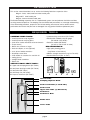
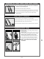
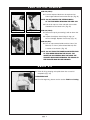
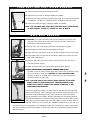
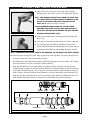
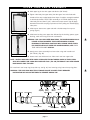
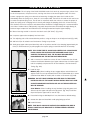
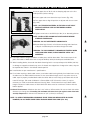
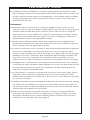
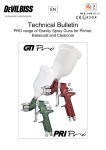
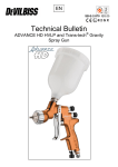
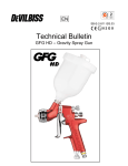
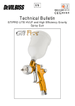
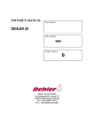
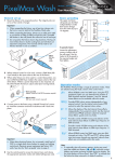
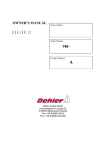
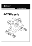
SERVICE MANUAL
1 9 9 6
For Mag 21: 1993, 1994, 1995
and 1996 model years
Mag 21SLTi: 1994 model year
Mag 10: 1993 and 1994 model years
RockShox, Inc.
1.800.677. 7177
INTRODUCTION
This service manual describes how to service the following RockShox suspension forks:
Mag 21: 1993, 1994, 1995 and 1996 model years
Mag 21SLTi: 1994 model year
Mag 10: 1993 and 1994 model years
The ROCK SHOX Mag suspension fork is a sophisticated system. Care and patience should be used when
servicing internal components. The damping units are oil-filled and pressurized, so a thorough understanding
of the disassembly procedure, proper tools and a clean working area must be used to achieve correct
performance and ensure that parts are not damaged. Use only genuine RockShox replacement parts.
REQUIRED TOOLS
COMMON HAND TOOLS:
• Small tip external snap ring pliers
• Small tip internal snap ring pliers
• 19 & 22mm socket and ratchet or box end wrench
• Torque wrench
• Metric ruler, 150mm or longer
• Precision calipers, 6 inch (optional)
• 32 & 36mm headset wrenches
• #1 phillips screw driver
• 1-liter beaker or container for used fork oil
• Safety glasses
• Straight blade screwdriver
• Bench vice
SPECIAL ROCK SHOX TOOLS:
1 Upper tube clamping blocks (PN 70101)
2 Seal/lower bushing installer (PN 70103)
3 Seal puller (PN 70113)
4 Valve body tool (PN 70105)
5 Drop-out vice blocks (PN 70107)
• Quadra bushing removal tool (PN 70106)
• ROCK SHOX standard pump/air gauge
(PN 20109—Not Shown)
• RockShox needle (PN 56991)
(no hole on side to tear air valve)
MISCELLANEOUS:
• High quality bearing grease
(Judy Butter or Non-Lithium)
• Medium strength thread lock (e.g. Loc-Tite 242)
• ROCK SHOX fork oil (5wt. or 8 wt.)
1
2
3
4
Steerer Tube
Damping Adjuster Knob
Fork Crown Bolts (2 each side)
Fork Crown
Upper Fork Tube (w/dust boot)
Fork Brace
Fork Brace Bolt
Brake Post
Lower Tube
page 1
5
R E M O VA L O F F O R K T U B E S F R O M F O R K C R O W N
Note: It is not necessary to remove the crown/steerer assembly from
the bike to service the damper units.
1. Disconnect front brake cable from brake lever.
2. Loosen fork crown bolts alternately to avoid putting too much clamping
force on one bolt and potentially stripping the bolt head (4mm hex key).
Figure 2A
3. Pull both lower fork tubes out of the crown with a slight rocking
motion. (Fig. 2A)
F O R K B R A C E R E M O VA L
1. Remove brakes as per manufacturer’s recommendations.
2. Remove both brake posts using an 8mm open end wrench. (Fig. 2B)
3. Remove both brace screws using a 4mm hex key.
4. Clean the exterior of both fork legs (use soap and water if necessary).
Figure 2B
DEPRESSURIZE FORK
1993 MAG 10
1993 MAG 21
1. MAG 10 (1993): Pry out upper tube dust cap from
the side. (Fig. 2C)
MAG 21 (1993): Remove air filler screw from the top
of the air cap using a #1 phillips screw driver. (fig 2D)
MAG 10 (1994) and MAG 21 (1994 and later):
Pry off rubber dustcap from top of air cap. (Fig. 2E)
2. Insert a RockShox needle (PN 56991) through the
exposed hole to depressurize the damper. (Fig. 2F)
Figure 2C
Figure 2D
WARNING: POINT NEEDLE AWAY FROM YOURSELF
AND OTHERS.
1994+ MAG 10/MAG 21
Figure 2E
Figure 2F
page 2
!
▲
F O R K A I R C A P R E M O VA L
1993 MAG 10
1993 MAG 10
MAG 10 (1993):
1. Push the exposed aluminum air cap down into
10mm upper tube and remove the wire clip. (Fig. 3A)
NOTE: DO NOT SCRATCH THE INTERIOR WALLS
OF THE TUBE WHEN REMOVING THE WIRE CLIP.
2. Pull the air cap out of the tube with a 6mm bolt
threaded into the center hole. (Fig. 3B)
Figure 3A
Figure 3B
1994 MAG 10
MAG 21
MAG 10 (1994):
1. Remove air cap by unscrewing it with an 8mm hex
key.
2. Inspect the adjuster head O-ring for signs of
wear or damage. Replace if necessary. (Fig. 3C)
MAG 21 (ALL):
1. Turn air cap counterclockwise with a 19mm (’93
MAG 21) or 22mm (’94 and later MAG 21) with
a socket or box wrench. (Fig. 3D)
Figure 3C
Figure 3D
NOTE: DO NOT FORCE THE DAMPING ADJUSTER KNOB
TO TURN WHEN REMOVING THE AIR CAP. THE
SOCKET OR BOX WRENCH MUST NOT GRAB THE
ADJUSTER KNOB WHEN REMOVING THE AIRCAP OR
THE ADJUSTER ROD WILL BE DAMAGED.
DRAIN OIL
1. Drain all oil by pumping unit upside down into a used oil
receptacle. (Fig. 3G)
PLEASE RECYCLE!
2. For oil change only, please see the section Fluid Level Setting.
Figure 3G
page 3
F O R K B O O T A N D D U S T W I P E R R E M O VA L
1. Remove fork boots by gently pulling up on them.
2. Inspect boots for wear or damage. Replace as needed.
3. Remove dust wiper by carefully prying up with a flat, blunt screw driver. (Fig.4A)
(’93 MAG 10, ’93 MAG 21, ’94 MAG 21 and ’94 MAG 21 SLTi forks only!)
4. Inspect dust wiper for wear or damage. Replace as needed.
Figure 4A
NOTE: THE FOLLOWING MAG FORKS WILL HAVE FORK BOOTS INSTALLED AND
NO DUST WIPERS: ’94 MAG 10, ’95 MAG 21, AND ’96 MAG 21.
M A I N S E A L R E M O VA L
Introduction: The upper and lower tubes are held together by the main seal
snap ring. After removing the main seal snap ring, the main seal must be
pulled out to separate the two tubes.
1. Remove main seal snap-ring using internal snap ring pliers. (fig 4B)
2. Extend upper and lower tubes to fully topped out position.
3. Place seal puller over tubes (tool #70113) with the larger end over lower tube.
Figure 4B
4. Clamp upper tube in a vice with the vice blocks against the small end of the
seal puller (tool#70101).
5. Unscrew seal puller by hand. For hard to remove main seals, refer to the
instructions below. (fig 4C)
6. Upper and lower tubes can now be pulled apart by hand. (fig 4D)
SPECIAL INSTRUCTIONS FOR HARD TO REMOVE MAIN SEALS:
If unable to remove seals by hand, apply heat to lower tube at location of seal
with a hot air gun or blow dryer. WARNING: DO NOT USE OPEN FLAME.
Carefully, continue to unscrew puller. If necessary, use 32mm and 36mm
headset wrenches on puller flats.
Figure 4C
NOTE: THE SNAP RING ON THE TOP-OUT SPRING CAN FAIL IF TOO MUCH
FORCE IS USED TO REMOVE MAIN SEAL. PROCEED CAREFULLY AND
SLOWLY. APPLY HEAT TO LOWER TUBE BEFORE ATTEMPTING TO USE
32MM AND 36MM WRENCHES.
If the top-out retaining ring fails, the upper tube will separate from the lower tube
and the seal, bushings, top-out spring and top-out retaining ring will remain in the
lower tube. Grab the bushings and the main seal with one end of the Quadra
bushing removal tool (PN 70106), slide the seal puller over the bushing removal
tool shaft and attach the end of the bushing removal tool to a bench vice. Use the
Figure 4C
seal puller to pull the bushings and main seal straight out from the lower tube. An
alternate method is to use a small, thin, flat-blade screwdriver to pry the main seal
from the lower tube—being careful not to damage the lower tube. The bushings, spacer, top-out spring
and top-out retaining ring should now slide out of the lower tube. Turn upside-down and tap the lower
tube on a bench.
page 4
!
▲
!
▲
U P P E R T U B E PA R T S E X P L A I N E D
1. Slide the seal, bushing washer, main seal O-ring, bushings,
bushing spacer, and top-out sleeve off the upper tube. (Fig. 5C)
NOTE: ONLY REMOVE THE VALVE BODY FROM THE UPPER TUBE
IF IT NEEDS SERVICE OR REPLACEMENT, OTHERWISE IT MAY
BE LEFT IN THE UPPER TUBE WHILE OVERHAULING THE
FORK. Skip to Upper Tube Parts Assembly.
Figure 5A
FOR DISASSEMBLED FORKS WHERE THE TOP-OUT SPRING
RETAINING RING FAILED, INSPECT SNAP RING GROOVE ON
VALVE BODY AND REPLACE AS NEEDED. USE ONLY GENUINE
ROCKSHOX REPLACEMENT PARTS.
2. Place inverted upper tube in clamping blocks (PN 70101) and
bench vice.
3. Insert pins, on valve body tool (PN 70105), into holes on valve body.
Figure 5B
4. Turn valve body tool (PN 70105) counterclockwise with a 19mm
wrench. Apply downward force while applying torque to valve body tool
to prevent tool from pulling out and damaging valve parts. (Fig. 5A)
NOTE: IF SERVICE OF THE TOP-OUT SPRING IS NOT REQUIRED, THE FOLLOWING STEP ME BE SKIPPED.
5. Remove top-out snap ring from valve body using external snap ring pliers. The top-out spring and topout washer should now slide off valve body. (Fig. 5B)
• 1993 MAG series forks (Mag 10 and Mag 21) have identical upper and lower bushings. The bushings
may be identified by the 1.126" (28.60mm) outside diameter.
• 1994 and later MAG series forks have different size upper and lower bushings. The upper bushing
outside diameter is larger than the lower bushing. Because the difference between the outside diameter
of the upper and lower bushings is very small, it is recommended that the upper bushing be marked to
avoid confusion. The lower bushing may be identified by the 1.126" (28.60mm) outside diameter. The
upper bushing may be identified by the 1.157" (29.39mm) outside diameter. For MAG series forks, the
1994 and later lower fork bushings are identical to the 1993 upper and lower fork bushings.
Top-out
Snap Ring
Top-out Sleeve Lower Bushing
Top-out
Spring
Upper Bushing
Bushing Spacer
Top-out
Washer
Valve Body
Main Seal
Seal O-ring
Bushing Washer
Figure 5C
page 5
Dust Wiper
Main Seal
Snap Ring
M A G 2 1 VA LV E PA R T S E X P L A I N E D
1. Screw adjuster rod all the way clockwise into valve body.
2. Remove E-clip from bottom end of adjuster rod using a small
straight-blade screwdriver. (fig 6A)
3. Unscrew adjuster rod from valve body.
4. Remove valve spring snap ring using snap ring pliers.
Figure 6A
5. Remove valve parts from adjuster rod. (fig 6B)
6. Inspect parts and replace as needed.
Figure 6B
Valve Body
Rebound Plate
Valve Spring Washer
(plastic)
Valve Spring
(aluminum)
E-clip
Adjuster Rod
Valve Plate
Valve Spring
Snap Ring
Figure 6C
’ 9 3 M A G 1 0 VA LV E PA R T S E X P L A I N E D
1. Hold valve body with tool (PN 70105) and remove valve bolt with
flat blade screwdriver.
2. Remove E-clip from valve bolt using a straight-blade screwdriver.
(Fig. 6D)
Figure 6D
3. The rebound washer, valve plate, valve spring, and spring
washer will now slide off.
4. Inspect parts and replace as needed.
Valve Body
Rebound Plate
(plastic)
E-clip
Valve Spring Washer
(preload)
Valve Plate
Valve Spring
Figure 6E
page 6
Valve Bolt
MAG COMPONENT INSPECTION
• All 1993 MAG series forks were assembled with stiff valve
springs (PN 44103). However, for 1994 and later MAG series
forks, the valve springs were softened (PN 44306) to improve
fork responsiveness. The valve springs are a tuning variable.
Figure 7A
• The 1993 MAG valve body had two intake port valves with a
compression bleed hole drilled 0.028" (0.71mm). 1994 and
later valve bodies (PN 42226) had four intake port valves with a
compression bleed hole drilled to 0.040" (1.02mm). The intake
port valves and the compression bleed hole are tuning variables.
• Another change made for the 1994 and later MAG series forks
were that the valve plate (PN 42327) was machined with a relief
step of 0.005".
Figure 7B
1. Check coating on inside of bushings and replace if scratched or
worn (brassy-colored). Replace bushings as needed. (fig 7A)
WARNING: BUSHINGS FROM 1993 REBUILD KIT WILL NOT WORK
CORRECTLY AS UPPER BUSHINGS FOR 1994 & LATER FORKS!
2. Check upper tube for signs of nicks or scratches that could
damage seal or inhibit proper seal function. Replace upper tube
as needed.
Figure 7C
3. Check all O-rings for evidence of tears, deformations or
scratches. Check rebound plate for deformations or scratches.
Replace as needed. (fig 7B)
4. Check main seal for deformations or scratches. Replace as
needed. (fig 7C)
Figure 7D
Figure 7E
NOTE: IT IS VERY RARE THAT A SEAL FAILS. THE PRIMARY
CAUSE OF SEAL LEAKAGE IS DUE TO DIRT WORKING INTO THE
LIPS OF THE SEAL OR A SCRATCHED OR DAMAGED UPPER
TUBE AND DISRUPTING THE SEAL’S FUNCTION. IN MOST
CASES, THEY MAY BE CLEANED AND REINSTALLED. PROPER
MAINTENANCE AND CLEANING OF THE UPPER TUBE AND
DUST WIPERS WILL PREVENT LEAKAGE.
5. Check top-out spring for correct free length. Measure spring
from end to end. Minimum length is 0.827" (21.0mm). Replace
as needed. (fig 7D)
6. Inspect fork brace at cable mount area for signs of damage
from crashes or misuse. (fig 7E)
NOTE: IF POSSIBLE, ADJUST THE HANDLEBARS TO HIT THE TOP
FRAME TUBE BEFORE THE FORK CAN SWING AROUND AND
THE CABLE MOUNT HITS THE DOWN TUBE.
Figure 7F
7. Inspect lower tubes for signs of damage at the drop-out area.
(fig 7F) Replace as needed.
page 7
!
▲
VA LV E A S S E M B LY
MAG 21
Valve Body
Rebound Plate
(plastic)
Valve Spring
E-clip
Adjuster Rod
Valve Spring
Washer
(aluminum)
Valve Plate
Valve Spring
Snap Ring
Figure 8A
1. Slide the following parts onto adjuster rod in the following order:
rebound plate, valve plate, valve spring, and valve spring
washers. (fig 8A)
2. Install valve spring snap ring on the damper rod using external
snap ring pliers. Place sharp side of snap ring away from valve
spring washer. (fig 8B)
Figure 8B
WARNING: BE CAREFUL NOT TO OVEREXTEND VALVE SPRING
SNAP RING WITH THE PLIERS.
!
▲
3. Screw adjuster rod assembly completely into valve body.
4. Install E-ring on bottom of adjuster rod.
5. Slide top-out washer onto valve body, followed by top-out spring,
and install valve spring snap ring (see fig. 9C) sharp side away
from top-out spring (Fig. 8A) to retain the assembly.
MAG 10
Valve Body
Rebound Plate
(plastic)
Valve Body
Valve Spring Washer
(preload)
Valve Plate
Valve Spring
Valve Bolt
Figure 8C
1. Slide the following parts onto valve bolt in the following order: valve spring washer, valve spring,
valve plate, and rebound washer. (fig 8C)
2. Install E-clip with sharp side of E-ring away from rebound plate.
3. Thread valve bolt assembly into valve body using a straight-blade screwdriver. Use medium strength
threadlock and torque to 36 IN-LBS (3.3 Nm).
WARNING: OVERTIGHTENING WILL BREAK THE VALVE BOLT.
page 8
!
▲
U P P E R T U B E PA R T S A S S E M B LY
1. Hold upper leg in vice with upper tube blocks (PN 70101).
2. Tighten valve body into upper tube, (the valve goes into end of tube with
threads all the way to edge) apply three drops of medium strength threadlock
to valve body threads. Torque valve assembly to 35 FT-LBS (48 Nm) using
valve body tool and 19mm (3/4") socket with torque wrench. (fig 9A) Apply
downward force while torquing to prevent tool from pulling out and damaging
valve ports.
Figure 9A
3. Slide top-out sleeve onto upper tube with shoulder away from top-out
spring. (fig 9C)
4. Slide lower bushing onto upper tube followed by the bushing spacer, upper
bushing, main seal O-ring, and main seal washer.
WARNING: FOR 1994 AND LATER MAG FORKS, THE UPPER BUSHING HAS A
LARGER OUTSIDE DIAMETER THAN LOWER BUSHING. PLACING
BUSHINGS IN THE WRONG POSITIONS WILL DAMAGE UPPER TUBES.
FOR IDENTIFICATION OF UPPER AND LOWER BUSHINGS, SEE UPPER
TUBE PARTS EXPLAINED SECTION.
!
▲
5. Gently press above assembly into lower tube using seal installer tool
(PN 70103). (Fig. 9B)
Figure 9B
6. Grease main seal inside and out. Place main seal over upper tube.
NOTE: INSTALL MAIN SEAL WITH SMALL SPRING SIDE FACING TOWARD INSIDE OF FORK. PRESS
SEAL INTO LOWER TUBE USING SEAL INSTALLER TOOL. (FIG. 9B) THE END OF TOOL WITH LARGER
BORE SHOULD FACE THE SEAL.
7. Install main seal snap ring (sharp side up, see fig. 9C) into lower leg using internal snap ring pliers.
WARNING: THE SNAP RING MUST FULLY ENGAGE GROOVE IN LOWER TUBE. IMPROPER
INSTALLATION MAY ALLOW THE TUBES TO SEPARATE DURING USE.
Top-out
Snap Ring
Top-out Sleeve
Lower Bushing
Top-out
Spring
Upper Bushing
Bushing Spacer
Top-out
Washer
Valve Body
Main Seal
Seal O-ring
Bushing Washer
Figure 9C
page 9
Dust Wiper
Main Seal
Snap Ring
!
▲
FLUID LEVEL SETTING
Introduction: The air spring of the ROCK SHOX MAG series forks works by compressing a volume of air.
As the air compresses, the pressure rises, causing more force to be exerted against tubes. This force
creates a progressive spring curve that resists bottoming. Changing the space of air inside the fork
dramatically alters the spring curve. Since oil is non-compressible, the level of oil inside the fork can be set
to create the optimal spring curve. The oil level is measured, rather than volume, to create the proper air
space and spring curve. Changing fork oil viscosity will change the damping of the fork. A lower viscosity
fork oil allows the fork to compress and rebound faster. RockShox 5 weight Racing Oil is recommended for
most riders. Heavier riders (>180 pounds) may prefer the performance of RockShox 8 weight Racing oil,
because larger compression and rebound forces will be generated and require higher damping.
1. Mount lower leg vertical in vice with vice blocks tools (PN 70107). (Fig. 10A)
2. Compress upper tube completely into lower tube.
3. Turn adjusting rod to full counterclockwise position, using an aircap or an old adjuster head. (Fig. 10B)
4. Add fork oil (for oil selection see Performance Tuning) to top of tube.
5. Slowly pump upper tube up and down fully until no air pockets are felt in the damping (approximately 10
times). It will be necessary to pull up against the top-out spring to reach full extension of assembly.
NOTE: PULL UPPER TUBE UP SLOWLY AND CAREFULLY OR A VACUUM MAY
FORM, CAUSING THE BOTTOM PLATE TO BECOME LOOSE. IF OIL IS
VISIBLE IN THE DROPOUT HOLE, THE LEG MUST BE COMPLETELY
DISASSEMBLED AND THE BOTTOM PLATE REINSTALLED.
6. Add or remove oil to obtain the correct oil level. To determine the oil level,
measure the distance between top of upper tube and top of oil when upper
tube is completely compressed. For oil level selection, see Performance
Tuning. (Fig. 10A)
Figure 10A
7. Install air cap:
MAG 21 (All): When installing air cap, engage adjuster rod with bottom of
adjuster head. Turn air cap clockwise with a 19mm (1993 MAG 21) or 22mm
(1994 and later MAG 21 models) with a socket or box wrench. (Fig. 10B)
WARNING: DO NOT FORCE DAMPING ADJUSTER KNOB TO TURN WHEN
INSTALLING AIR CAP. THE SOCKET OR BOX WRENCH MUST NOT GRAB
ADJUSTER KNOB WHEN INSTALLING AIR CAP OR THE ADJUSTER ROD
WILL BE DAMAGED.
Figure 10B
MAG 10
1993 MAG 10: When installing air cap, lubricate O-ring with grease and
slide air cap into upper tube past wire clip groove. (Fig. 10C) Install wire
clip and compress upper tube to seat air cap.
8. Pressurize fork legs to 80-100psi for 1 hour, then lower to desired setting.
9. Grease dust wiper and install with small spring facing top of fork.
10. Install fork boots.
Figure 10C
NOTE: FORK BOOTS SHOULD BE INSTALLED FOR OWNERS WHO RIDE IN
MUDDY CONDITIONS, OR WHO WANT TO EXTEND INTERVALS BETWEEN
MAINTENANCE.
page 10
!
▲
F O R K I N S TA L L AT I O N I N T O C R O W N
1. Clean upper tube of all oil and set damping adjuster to the first
index position (softest setting).
2. Insert upper tube 3mm above the top of crown. (Fig. 11A)
3. Turn upper tube to align #1 position on adjuster with slot on crown.
(Fig. 11B)
NOTE: ALL TITANIUM FASTENERS ON THE MAG 21 SLTi MUST
HAVE ANTI-SEIZE OR LUBE ON THE THREADS DURING
INSTALLATION.
Figure 11A
4. Tighten crown bolts to 60 IN-LBS (6.8 Nm) in an alternating fashion.
NOTE: INSTALL STEEL CROWN BOLTS WITH AMPLE MEDIUMSTRENGTH THREADLOCK.
WARNING: DO NOT OVERTIGHTEN CROWN BOLTS.
!
▲
5. Rotate lower legs forward, so fork brace mounting holes face front
of bicycle. Install brake posts and bolts through fork brace.
Figure 11B
WARNING: TO AVOID DAMAGE TO MAGNESIUM THREADS WHEN
INSTALLING FORK BRACE, PLEASE OBSERVE STEPS 6 & 7
CAREFULLY.
!
▲
6. Use ample medium-strength threadlock on brake posts and fork brace bolts. The correct torque for all
years and models of MAG series forks is only 60 IN-LBS (6.8 Nm) for brake posts and brake bolts.
7. When installing brakes, be certain that brake fastening bolt is not torqued beyond 60 IN-LBS (6.8 Nm)
or damage to magnesium threads may occur. If threads are stripped out of magnesium tubes, they can
be repaired with a M6 X 1 X 9 Helicoil thread repair kit.
8. Install brakes as per manufacturer’s specifications.
9. For a brake requiring a brake cable mount, route brake cable housing directly from brake levers to top
of cable mount on ROCK SHOX fork brace. Do not route cable through stem or any other mounts or
cable stops! A properly installed brake cable should be able to move freely up and down with the full
travel of fork legs. Full travel for MAG 21 is 50mm (MAG 21 LT full travel is 63mm). It may be
necessary to install a new brake cable and housing. Note: The distance from top of brake cable
hanger to bottom of cable mount on ROCK SHOX fork brace must be a minimum of 12mm with the
brakes applied.
10.Check Tire Clearance: Maximum tire size is 2.2" wide or 335mm radius. Be sure to check this radius
whenever you change tires. Exceeding this maximum will cause tire to jam against crown when forks
are fully compressed. A minimum tire clearance of 1/4" (6.4mm) is necessary.
NOTE: TO OBTAIN THE REQUIRED CLEARANCE, UPPER TUBES MAY BE ADJUSTED IN CROWN.
HOWEVER, DO NOT RAISE UPPER TUBES IN CROWN MORE THAN 3MM! (FIG. 11C)
page 11
!
▲
SL UPGRADE KITS
Installation of the EA-70 upper tubes and SL aircaps
1. Complete the following sections located in this manual:
REMOVAL OF FORK TUBES
DEPRESSURIZE FORK
FORK AIR CAP REMOVAL
DRAIN OIL
FORK BOOT AND DUST WIPER REMOVAL
MAIN SEAL REMOVAL
2. Complete steps 1 through 5 in UPPER TUBE PARTS EXPLAINED.
THE VALVE BODY IS TIGHTENED AT THE FACTORY ONTO THE STEEL UPPER TUBE WITH 35 FT-LBS OF
TORQUE AND BLUE LOC-TITE. THEREFORE IT IS ON VERY TIGHT. TO AVOID DAMAGE TO BOTH THE
VALVE TOOL AND THE VALVE BODY, IT MAY BE NECESSARY TO APPLY A PENETRATING OIL OR USE
MILD HEAT TO LOOSEN THE THREADLOCK. APPLY DOWNWARD FORCE SO VALVE BODY TOOL
DOES NOT WALK OUT OF VALVE BODY.
!
▲
3. Clean old threadlock from threads of valve body, do not use Loc-Tite on EA-70 upper tubes.
4. Install valve body into new EA-70 Taperwall upper tubes. Turn to Upper Tube Parts Assembly, step 1,
to finish installation.
L O N G T R AV E L C O N V E R S I O N
Required parts:
Mag 10/Mag 21 Long Travel Kit (PN 59030) or Mag 10/Mag 21 Performance Tuning Kit (PN 59025)
1. Complete the following sections located in this manual:
REMOVAL OF FORK TUBES
DEPRESSURIZE FORK
FORK AIR CAP REMOVAL
DRAIN OIL
FORK BOOT AND DUST WIPER REMOVAL
MAIN SEAL REMOVAL
2. Complete steps 1 through 5 in UPPER TUBE PARTS EXPLAINED.
THE VALVE BODY IS TIGHTENED AT THE FACTORY ONTO THE STEEL UPPER TUBE WITH 35 FT-LBS OF
TORQUE AND BLUE LOC-TITE. THEREFORE IT IS ON VERY TIGHT. TO AVOID DAMAGE TO BOTH THE
VALVE TOOL AND THE VALVE BODY, IT MAY BE NECESSARY TO APPLY A PENETRATING OIL OR USE
MILD HEAT TO LOOSEN THE THREADLOCK. APPLY DOWNWARD FORCE SO VALVE BODY TOOL
DOES NOT WALK OUT OF VALVE BODY.
3. Exchange the cross-country travel top-out sleeve (PN 53124) with a long travel top-out sleeve (PN
53123) in both legs.
4. Read Performance Tuning and Performance Settings and perform the recommended modifications.
5. Continue with instructions in Valve Parts Explained to finish installation.
page 12
!
▲
PERFORMANCE TUNING
The standard RS settings are designed for use by riders weighing between 140 and 180 lbs. (65-80
Kgs), and riding on a variety of cross country-type conditions. When the MAG series forks will be used
by riders outside of this weight range or for other applications, such as downhill racing, the following
settings should yield greater suspension performance. But first, it’s best to know how the ROCK
SHOX MAG series fork works.
The Basics:
RockShox MAG series forks are based on an air spring/oil damped suspension system. An air/oil
suspension system is really two components working together at the same time—an air spring and an
oil damper (shock absorber). Most modern suspension systems utilize some form of spring and
damper mechanism. A car, for example, uses a steel coil or leaf spring and an oil damper. However,
steel springs are much heavier than an air spring. For this reason, a lightweight air spring and oil
damped suspension system is more appropriate for bicycles.
Suspension works by allowing the wheel to quickly move up and down with the irregularities of the
ground without moving the mass of the rider or vehicle with it. This means the wheel can stay on the
ground, improving control and “ground feel” for the rider.
The suspension should move as much as possible to follow the ground without bottoming out (hitting the
end of its travel). Depending on the bump size and how fast it is hit, the suspension varies in
firmness to prevent bottoming, but the spring and damper do it in different ways. The spring changes
according to how much it is compressed, while the damping changes according to the speed of the
force put into it (how fast it compresses). This combination means the suspension can sense
whether the wheel hits a big or small bump, or how fast or slow, and adjust its firmness accordingly.
The damping also has a second function of controlling the rebound (extension) action of the suspension.
A spring alone will rebound at different speeds depending on how much it has been compressed, and
this would make the suspension movement very unpredictable. The rebound damping allows the
suspension to rebound at a predictable speed.
The air spring stiffness, or spring rate, can be altered in many ways to suit the rider’s weight, terrain or
riding style. It can be made stiff in the beginning of the travel to stay more extended on steep
downhills where more weight is on the front end, or stiff at the end so it won’t bottom out over jumps
or if the rider is very heavy.
The damping can likewise be tuned. The damping can be adjusted so that the fork moves when travelling
over small bumps, like washboards, yet can be firm to absorb a large bump hit at high speed. The
fork can also be tuned to be rigid while pedaling by creating a minimum force threshold that must be
overcome before the suspension can move normally.
While all this may sound simple, the possible combinations are endless and many potentially bad
performance side effects can arise from any change made to the spring or damping. So, to make
tuning easier, RockShox has come up with the following selection of special settings that can be
safely made to suit a particular rider’s needs (page 14).
page 13
S TA N D A R D R O C K S H O X S E T T I N G S
MAG 21
MAG 10
Air pressure:
38 – 42 Psi
38 – 42 Psi
Oil height:
40 – 45 mm
45 – 50 mm
Oil viscosity:
SAE 5 wt (RockShox)
SAE 5 wt (RockShox)
Valve spring preload:
0 – .5 mm
0 – .5 mm
Rebound bleed hole(s):
none
none
Compression Bleed hole:
.040" (1.0mm) Std
.040" (1.0mm) Std
Travel:
Standard (46mm)
Standard (46mm)
PERFORMANCE SETTINGS
CROSS COUNTRY SETTINGS
LIGHT RIDER (less than 140lbs.)
HEAVY RIDER (+ 180lbs.)
MAG 21
MAG 10
MAG 21
MAG 10
Air pressure:
35 – 40 Psi
35 – 40 Psi
Air pressure:
42 – 48 Psi
42 – 48 Psi
Oil height:
45 – 50 mm
50 – 55 mm
Oil height:
35 – 40 mm
40 – 45 mm
Oil viscosity:
SAE 5 wt (RockShox)
SAE 5 wt (RockShox)
Oil viscosity:
SAE 8 wt (RockShox)
SAE 8 wt (RockShox)
Valve spring preload:
0 – .5 mm
0 – .5 mm
Valve spring preload:
.5 mm – 1.0 mm
.5 mm – 1.0 mm
Rebound bleed hole(s):
none
none
Rebound bleed hole(s):
none
none
Compression Bleed hole: 1.5 mm
Standard (1.0mm)
Compression Bleed hole: Standard (1.0mm)
Standard (1.0mm)
Travel:
Standard (46mm)
Travel:
Standard (46mm)
Standard (46mm)
Standard (46mm)
DOWNHILL SETTINGS
For MAG 10/MAG 21 forks with Long Travel Kit (PN 59030) or Performance Tuning Kit (PN 59025)
LIGHT RIDER (less than 140lbs.)
HEAVY RIDER (+ 180lbs.)
MAG 21
MAG 10
MAG 21
MAG 10
Air pressure:
38 – 42 Psi
38 – 42 Psi
Air pressure:
42 – 50 Psi
42 – 50 Psi
Oil height:
40 – 45 mm
45 – 50 mm
Oil height:
30 – 35 mm
30 – 35 mm
Oil viscosity:
SAE 5 wt (RockShox)
SAE 5 wt (RockShox)
Oil viscosity:
SAE 8 wt (RockShox)
SAE 8 wt (RockShox)
Valve spring preload:
0 – .5 mm
0 – .5 mm
Valve spring preload:
0 – .5 mm
0 – .5 mm
Rebound bleed hole(s):
2 X 1.0 mm
2 X 1.0 mm
Rebound bleed hole(s):
none
none
2.0 mm
Compression Bleed hole: 1.5 mm
Compression Bleed hole: 2.0 mm
Travel:
Long Travel (60 mm) Long Travel (60 mm)
Travel:
AVERAGE RIDER (140–180lbs.)
MAG 21
MAG 10
Air pressure:
40 – 45 Psi
40 – 45 Psi
Oil height:
35 – 40 mm
40 – 45 mm
Oil viscosity:
SAE 5 wt (RockShox)
SAE 5 wt (RockShox)
Valve spring preload:
0 – .5 mm
0 – .5 mm
Rebound bleed hole(s):
1 X 1.0 mm
1 X 1.0 mm
Compression Bleed hole: 2.0 mm
Travel:
2.0 mm
Long Travel (60 mm) Long Travel (60 mm)
page 14
1.5 mm
Long Travel (60 mm) Long Travel (60 mm)
WA R R A N T Y
ROCKSHOX, INC. WARRANTS ITS FORKS FOR A PERIOD OF ONE YEAR FROM ORIGINAL DATE OF PURCHASE TO BE FREE FROM DEFECTS IN MATERIALS OR WORKMANSHIP. ANY ROCKSHOX
FORK THAT IS RETURNED TO THE FACTORY AND IS FOUND BY ROCKSHOX TO BE DEFECTIVE IN MATERIALS OR WORKMANSHIP WILL BE REPAIRED OR REPLACED AT THE OPTION OF ROCKSHOX,
INC. THIS WARRANTY IS THE SOLE AND EXCLUSIVE REMEDY. ROCKSHOX SHALL NOT BE HELD LIABLE FOR ANY INDIRECT, SPECIAL OR CONSEQUENTIAL DAMAGES.
THE WARRANTY DOES NOT APPLY TO FORKS WHICH HAVE NOT BEEN PROPERLY INSTALLED AND ADJUSTED ACCORDING TO ROCKSHOX INSTALLATION INSTRUCTIONS. THE WARRANTY DOES
NOT COVER ANY FORK THAT HAS BEEN SUBJECT TO MISUSE OR WHOSE SERIAL NUMBER HAS BEEN ALTERED, DEFACED OR REMOVED. THIS WARRANTY DOES NOT COVER PAINT DAMAGE
OR MODIFICATIONS TO FORKS. PROOF OF PURCHASE IS REQUIRED.
Warranty Repair
IF FOR ANY REASON IT SHOULD BE NECESSARY TO HAVE WARRANTY WORK DONE, RETURN THE FORK TO THE PLACE OF PURCHASE. IN THE USA, DEALERS SHOULD CALL FOR A RETURN
AUTHORIZATION (RA#) PRIOR TO RETURNING PRODUCT. PRODUCTS RETURNED FOR INSPECTION MUST BE SENT FREIGHT PREPAID TO:
ROCKSHOX, INC.
401 CHARCOT AVE.
SAN JOSE, CA 95131
408.435.7469
FAX 408.435.7468
CUSTOMERS IN COUNTRIES OTHER THAN THE USA SHOULD CONTACT THEIR DEALER OR LOCAL DISTRIBUTOR.
page 15