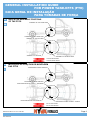
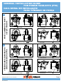
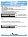
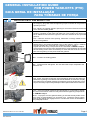
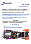
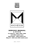
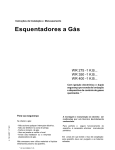
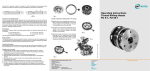
1
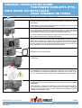
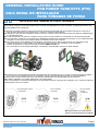
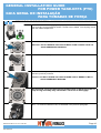
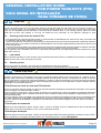
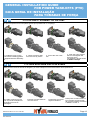
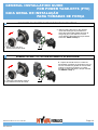
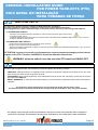
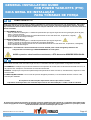
GENERAL INSTALLATION GUIDE
FOR POWER TAKE-OFFS (PTO)
GUIA GERAL DE INSTALAÇÃO
PARA TOMADAS DE FORÇA
01 ATTENTION: SAFETY INFORMATION
PTOs should be mounted by qualified personnel.
GB -- The
Use suitable tools and measurement instruments.
-
Use personal protections and precautions set out by the current regulation on safety in the workplace.
Avoid assembling or disassembling the PTOs on your own.
Ensure the system or the PTO cannot involuntarily started up.
Do not assemble the PTO or parts of the PTO or conduct maintenance work when the engine is on.
Ensure all the components have been assembled properly and the level of oil in the gear box has been topped up
before starting up the vehicle: incorrect assembly of the PTO may cause the PTO and/or the gearbox to break and
damage other parts of the vehicle.
The splined shaft (male or female) protruding from the PTO rotates with no protection when the pump has
not been assembled. Avoid any contact between the shaft and any object and, more importantly, protect the wor
king area to prevent contact with body parts or clothing.
Install the pump or the cardan shaft only when the engine is off and the PTO has been disconnected.
For the assembly of the cardan shaft, it is necessary to use all the precautions and protections set out by the
current regulation on safety in the workplace.
The gearbox or the PTO may attain high very temperatures after prolonged use of the vehicle or the PTO. It is
therefore necessary to take all the necessary measure to prevent burns or wait for the mechanical parts to cool
down to temperatures appropriate for skin contact.
Some PTOs are considerably heavy and to assemble and disassemble them it is necessary to use adequate lifting
or resting systems to prevent crushing hazards.
Any waste oil or that has not been used should not be discarded in the environment, but should be processed
according to the directives included in current regulation on the disposal of special waste.
All metal or rubber parts discarded during assembly or disassembly of the PTOs should be disposed of in com
pliance with current regulation on the disposal of special waste.
01 ATENÇÃO: INFORMAÇÃO DE SEGURANÇA
- A Tomada de força deve ser montada por técnicos qualificados;
P - Usar ferramentas corretas e instrumentos de medição apropriados;
- Usar EPIs e tomar as devidas precauções de acordo com o ambiente de trabalho;
- Evite montar e desmontar a PTO sem a ajuda de outro técnico;
- Tenha certeza que o sistema ou a PTO não irá entrar em funcionamento voluntariamente;
- Não monte a PTO ou as peças da PTO ou execute quaisquer tipos de manutenção com o motor em funcionamento;
- Certifique-se que todos os componentes foram montados corretamente e o nível do óleo na caixa de transmissão
foi completado antes de ligar o veículo: a montagem incorreta da PTO pode causar falha da PTO e/ou da caixa de
transmissão e danificar outras partes do veículo;
- O eixo estriado (macho ou fêmea) que sai da PTO gira sem proteção quando a bomba não foi instalada. Evite
qualquer contato entre o eixo e qualquer objeto e, ainda mais importante, proteja a área de trabalho para prevenir
contato com partes do corpo ou da roupa;
- Instale a bomba ou o eixo cardan somente quando o motor está desligado e a PTO está desligada;
- Para a montagem do eixo do cardan, é necessário usar todas as precauções e proteções definidas pelos padrões
de segurança do local de trabalho;
- A caixa de transmissões ou a PTO podem acumular temperaturas muito altas depois de longos tempos de funcionamento do veículo ou da PTO. É portanto necessário tomar todas as providencias para prevenir queimaduras
ou esperar que as peças esfriem para poder realizar o serviço de instalação e/ou manutenção;
- Algumas PTOs são consideravelmente pesadas e para montar e desmontar as PTOs é necessário utilizar equipamentos adequados para auxiliar o manejo dessas peças ou sistemas de apoio para prevenir quedas bruscas destes
componentes;
- Qualquer desperdício de óleo ou quantidade de óleo que não foi utilizada não deve ser descartado no meio ambiente, mas sim deve ser descartado de maneira apropriada, obedecendo as políticas de descarte desses resíduos;
- Todas as peças de metal ou de polímero descartadas durante a montagem ou desmontagem da PTO deve ser
descartada de acordo com as regras vigentes de descarte de material.
OH-E PTO-0014 / 15 10 14 / RV AG
001-00007HY
Page 1
GENERAL INSTALLATION GUIDE
FOR POWER TAKE-OFFS (PTO)
GUIA GERAL DE INSTALAÇÃO
PARA TOMADAS DE FORÇA
02
GB
INDICATIVE ASSEMBLY POSITIONS
OF THE PTOS
ASSEMBLY OF THE UPPER PART
ASSEMBLY OF THE LOWER PART
ASSEMBLY OF THE LEFT SIDE
ASSEMBLY OF THE REAR
ASSEMBLY OF THE RIGHT SIDE
OUTLET REAR SHAFT
OUTLET FRONT SHAFT
02
P
INDICAÇÃO DE POSIÇÕES DE MONTAGEM
DAS PTOS
MONTAGEM NA PARTE SUPERIOR
MONTAGEM NA PARTE INFERIOR
MONTAGEM NA PARTE LATERAL – ESQUERDA
MONTAGEM NA PARTE POSTERIOR
MONTAGEM NA PARTE LATERAL – DIREITA
Eixo de saída traseiro
Eixo de saída dianteiro
OH-E PTO-0014 / 15 10 14 / RV AG
001-00007HY
Page 2
GENERAL INSTALLATION GUIDE
FOR POWER TAKE-OFFS (PTO)
GUIA GERAL DE INSTALAÇÃO
PARA TOMADAS DE FORÇA
GB
RULES APPLYING TO THE DIRECTION OF ROTATION OF THE PTO OUTPUT SHAFT
CLOCKWISE
ANTICLOCKWISE
P
CLOCKWISE rotation
Application - LEFT pump
ANTICLOCKWISE rotation
Application - RIGHT pump
REGRAS DE APLICAÇÃO SEGUNDO A DIREÇÃO DE ROTAÇÃO
DO EIXO DE SAIDA DA PTO
SENTIDO HORARIO
SENTIDO ANTI HORARIO
OH-E PTO-0014 / 15 10 14 / RV AG
001-00007HY
ROTAÇÃO HORARIA
Aplicação – bomba esquerda
ROTACAO ANTI-HORARIA
Aplicação - bomba direita
Page 3
GENERAL INSTALLATION GUIDE
FOR POWER TAKE-OFFS (PTO)
GUIA GERAL DE INSTALAÇÃO
PARA TOMADAS DE FORÇA
3-hole/rear
MOST COMMON PTO SHAFT
OUTLET VERSION
GB
Male shaft 6x21x25 (ISO14)
Rear outlet
flange
Male shaft 8x32x36 (ISO14) Rear outlet
This version always requires the flange
3 furos/traseiro
VERSÕES MAIS COMUNS DOS
EIXOS DE SAÍDA DAS PTOs
P
eixo macho 6x21x25 (ISO14)
saída traseira
flange
eixo macho 8x32x36 (ISO14) saída traseira
Esta versão sempre requer a flange
OH-E PTO-0014 / 15 10 14 / RV AG
001-00007HY
3-hole/forward
Male shaft 6x21x25 (ISO14)
Front outlet
4-hole/rear
Female hub 8x32x36 (ISO14)
Rear outlet
3 furos/dianteiro
eixo macho 6x21x25 (ISO14)
saída dianteira
4 furos/traseiro
Cubo fêmea 8x32x36 (ISO14)
Saída traseira
Page 4
GENERAL INSTALLATION GUIDE
FOR POWER TAKE-OFFS (PTO)
GUIA GERAL DE INSTALAÇÃO
PARA TOMADAS DE FORÇA
03 GB
GENERAL INFORMATION TO MOUNT POWER TAKE-OFFS
- Carefully follow these general assembly indications, both as far as the safety precautions and the assembly stages of
the PTOs are concerned.
- The general indications do not replace specific instructions contained in the PTOs, in the assembly kit or in the various
assembly accessori es (adapters, auxiliary shafts, etc).
- It is necessary to also follow any instructions related to the vehicle’s gearbox.
- Install the PTO’s with the vehicle placed on a flat surface, so that oil levels in the gearbox can be checked correctly.
- Only use the components contained in the PTO packaging and related accessories (assembly kit, auxiliary shafts,
adapters).
- Only use gaskets supplied.
- Do not use sealing paste, unless explicitly indicated in the specific instructions.
- It is advisable to use a medium-strength threadlocker to tighten the studs and screws.
- Before assembling the PTO, check that the vehicles clutch and transmission work correctly and that the gearbox does
no produce any anomalous noises or issues in inserting some gears.
TABLE 3
TIGHTENING TORQUE
Thread diameter - Screw (mm) M8
M10
M12
UNC 3/8
UNC 7/16
Screws and nuts torque
(Nm)
25
50
80
25
60
Studs torque
(Nm)
10
20
30
10
20
03
P
For aluminium gearboxes the tightening torque needs to be reduced by 30%. Note on the
tightening torque: the tightening torques reported are only means as a guide and do not
replace the indications given by the vehicle’s
manufacturer of the gearbox manufacturer.
INFORMAÇÕES GERAIS PARA MONTAGEM DAS TOMADAS DE FORÇA
- Cuidadosamente siga estas regras gerais de montagem, inclusive as medidas de precauções e as etapas de montagem da PTO;
- As indicações gerais não substituem as instruções contidas na PTOs, a montagem do kit ou as diversas partes e acessórios que acompanham a PTO.
- Utilize somente as gaxetas fornecidas com o conjunto;
- Não utilize cola seladora ou de vedação, a não ser que seja explicitamente indicado nas instruções específicas;
- É aconselhável usar um selador de média-força para apertar os prisioneiros e parafusos*;
- Antes de montagem da PTO, verifique que a embreagem do veículo e a transmissão trabalham corretamente e que a
caixa de transmissão não produz nenhum ruído anormal ou outros sintomas quando engrenando as marchas.
TORQUE DE MONTAGEM
TABELA 3 ! Para algumas caixas de transmissão de alumí-
Diâmetro da rosca – Parafuso
(mm)
M8
M10
M12
UNC 3/8
UNC 7/16
Parafusos e porcas de
montagem
(Nm)
25
50
80
25
60
Torque dos prisioneiros
(Nm)
10
20
30
10
20
OH-E PTO-0014 / 15 10 14 / RV AG
001-00007HY
nio o torque de montagem deve ser reduzido em
30%. Note que os torques de aperto são apenas
uma orientação e não prevalecem sobre os torques de montagem indicados nos manuais de
cada PTO e do fabricante da caixa de transmissão
Page 5
GENERAL INSTALLATION GUIDE
FOR POWER TAKE-OFFS (PTO)
GUIA GERAL DE INSTALAÇÃO
PARA TOMADAS DE FORÇA
04
GB
INSTALLATION OF SIDE MOUNT PTOS
4.1 - Unscrew the emptying plug and remove the oil from the gearbox. Screw
the emptying plug back with the tightening torque indicated in the gearbox’s
operating manual.
4.2 - Identify the suitable gearbox opening to mount the PTO and remove the
cover with the related gasket.
4.3 - Check that the gearing is compatible with the PTO’s gearing in terms of
position, inclination of the tooth and teeth size. This needs to be carried out
as an additional check that the right PTO has been selected for the specified
gearbox.
4.4 - Clean the surface of the opening, make sure no foreign matter is introduced in the gearbox.
4.5 - If the PTO needs to be mounted with studs, insert them (with the short
thread side) in the related threaded holes of the gearbox, using a mediumstrength threadlocker (LOCTITE 243, LOXEAL 55-03 or similar).
Tighten the studs using a torque like the one indicated in TABLE 3 Chap.3.
If the gearbox has feed-through threaded holes, the threadlocker should also
have a sealing action and it is necessary to check that the studs do not interfere with the gearing of with parts inside the gearbox.
4.6 - Position the sealing gasket.
4.7 - Install the PTO and tighten the nuts with lower torque compared to the
definitive one.
(A)
4.8 - Check, through the inspection hole (indicated by the arrow) the clearance
between the gearings. The clearance should be between 0.15 and 0.3 mm (A).
The clearance is controlled manually and therefore it cannot be precise. This is
why it is necessary to proceed by attempts until the optimal clearance is achieved.
4.9 - Once the optimal clearance has beet defines, it is necessary to tighten
the nuts or the screws of the PTO fully home with the tightening torque shown
in TABLE 3 Chap.3.
4.10 - Top up the oil in the gearbox bearing in mind that usually a side mount
PTO uses up approximately 0.5 –0.8 litres of oil. Install the control system.
Start up the vehicle and engage the PTO. Conduct the checks as illustrated in
the paragraphs below.
OH-E PTO-0014 / 15 10 14 / RV AG
001-00007HY
Page 6
GENERAL INSTALLATION GUIDE
FOR POWER TAKE-OFFS (PTO)
GUIA GERAL DE INSTALAÇÃO
PARA TOMADAS DE FORÇA
04
P
INSTALAÇÃO DAS PTOS MONTADAS LATERALMENTE
4.1 Retire o tampão da caixa de transmissão para retirar o óleo da caixa.
Parafuse novamente o tampão com o torque indicado no manual da caixa de
transmissão.
4.2 Identifique a saída apropriada da caixa de transmissão para montar a PTO
e remova a tampa e a junta de vedação.
4.3 Verifique se o engrenamento é compatível entre o câmbio e a PTO em
termos de posição, inclinação do dentado e tamanho do dente. Isso precisa
ser considerado como uma checagem adicional para verificar se a PTO foi
selecionada corretamente para a caixa de transmissão específica.
4.4 Limpe a superfície de abertura, tomando os devidos cuidados para evitar
que contaminantes entrem na caixa de transmissão.
4.5 Se a PTO precisa ser montada com prisioneiros, rosqueie eles (com o
lado da rosca curta) nos furos roscados da transmissão, usando um aperto
médio. Usar LOCTITE 243, LOXEAL 55-03 ou similar. Se a caixa de transmissão tem os furos passantes, tomar cuidado para os prisioneiros não ultrapassarem a espessura da carcaça da caixa de transmissão, caso contrário pode
haver interferência com as engrenagens da transmissão.
4.6 Posicione a junta de vedação;
4.7 Instale a PTO e aperte as porcas com um torque baixo se comparado com
o torque final.
4.8 Verifique, através do furo de inspeção (indicado pela flecha) a folga entre
as engrenagens. A tolerância da folga deve variar entre 0,15 mm e 0,30 mm
(A). A tolerância é controlada manualmente e portanto não é precisa. É por
isso que é necessário fazer tentativas até a tolerância ótima ser alcançada.
(A)
4.9 Uma vez que a tolerância ótima foi alcançada, é necessário apertar as
porcas até que a PTO esteja completamente sob o torque mostrado na tabela
3 capítulo 3.
4.10 Complete o nível de óleo sabendo que uma PTO montada lateralmente consome aproximadamente 0.5 a 0.8 litros de óleo. Instale o sistema de
controle. Inicie o veiculo e acione a PTO. Conduza as verificações conforme
ilustrado nos parágrafos abaixo.
OH-E PTO-0014 / 15 10 14 / RV AG
001-00007HY
Page 7
GENERAL INSTALLATION GUIDE
FOR POWER TAKE-OFFS (PTO)
GUIA GERAL DE INSTALAÇÃO
PARA TOMADAS DE FORÇA
05
GB
INSTALLATION OF THE REAR PTOS
The installation of the rear PTOs is conducted according to the type of PTO and the accessories to install. It is necessary
to check and follow the specific instructions contained in the adapters and the auxiliary shafts. The indications below are
meant as a guide.
5.1 - Empty the oil of the gearbox (for some gearboxes there is no need to empty the oil as the level does not reach the
rear door – check the gear box’s operating manual).
5.2 - Identify the rear opening and remove its cover and gasket. The gasket removed should not be used to assemble
the PTO.
5.3 - Clean the surface of the door, make sure no foreign matter is introduced in the gearbox
5.4 - If necessary, install the auxiliary shaft and/or adapters following the specific instructions with special care for
cases where it is necessary to adjust the bearings with cone-shaped rollers.
5.5 - If the PTO needs to be assembled with studs, insert them (con the short thread side) in the related threaded holes
using a medium-strength threadlocker (LOCTITE 243, LOXEAL 55-03 or similar). Tighten the studs using a torque
like the one indicated in TABLE 3 Chap.3.
If the gearbox has feed-through threaded holes, the threadlocker should also have a sealing action.
5.6 - Install the PTO on the gearbox and tighten the nuts or screws (also in case of screws make use of a mediumstrenght threadloker) with the tightening torque indicated in the table.
IF THE PTO HAS NO OIL SEAL, IT IS NECESSARY TO MOUNT THE PUMP BEFORE EXECUTING THE
LISTED CONTROLS.
5.7 - Top up the oil in the gearbox bearing in mind the higher demand of oil due to the presence of the PTO.
5.8 - Install the fitting and the air coupling pipe.
For rear PTO with 2 wheel it is recommended, to optimise the lubrication of internal parts, to company with the assembly
positions indicated.
PTO Vertical
ASSEMBLY
-Low outlet
PTO Horizontal
ASSEMBLY
PTO Vertical
ASSEMBLY
-High outlet
High outlet only with lubrication kit allowed,
yet not advisible.
OH-E PTO-0014 / 15 10 14 / RV AG
001-00007HY
Page 8
GENERAL INSTALLATION GUIDE
FOR POWER TAKE-OFFS (PTO)
GUIA GERAL DE INSTALAÇÃO
PARA TOMADAS DE FORÇA
05
P
INSTALAÇÃO DAS TOMADAS DE FORÇA TRASEIRAS
A instalação da PTOs traseira é conduzida de acordo com o tipo de PTO e os acessórios para a instalação. É necessário checar e seguir as instruções específicas contidas nos adaptadores e eixos auxiliares. As indicações abaixo são
disponibilizadas como referência.
5.1 Esvazie a caixa de câmbio do óleo (em algumas caixas de transmissão não é necessário esvaziar a caixa pois o
nível do óleo está abaixo do nível da PTO – checar no manual do proprietário).
5.2 Identificar a abertura de montagem traseira e remover a tampa e junta. A junta removida não deve ser utilizada para
a montagem da PTO.
5.3 Limpe a superfície de abertura, certifique-se que nenhum corpo estranho é introduzido na caixa de transmissão.
5.4 Se necessário, instale um eixo auxiliar e/ou adaptadores seguindo as respectivas instruções com o cuidado de especial para os casos onde é necessário ajustar os rolamentos com rolos cônicos.
5.5 Se a PTO precisa ser instalada com prisioneiros, insira eles (com o lado da rosca curta) nos respectivos furos
roscados usando um torque médio e um fixador de rosca (LOCTITE 243, LOXEAL 55-03 ou similar).
Aperte os prisioneiros usando um torque conforme TABELA 3 Cap. 3.
Se a caixa tem furos de fixação passantes, o fixador de rosca também deve ter um efeito selador.
5.6 Instale a PTO na caixa de transmissão e aperte as porcas ou parafusos com o torque de aperto indicado na tabela.
Se a PTO não tem vedação de óleo, é necessário montar a bomba antes de executar os controles listados.
5.7 Preencha o nível do óleo tendo em mente a maior demanda de óleo exigida pela presença da PTO.
5.8 Instale o adaptador e o engate rápido para o ar pressurizado.
Para a PTO traseira com duas engrenagens é recomendado observar a posição de montagem com o intuito de melhorar
a lubrificação conforme indicado.
PTO montagem vertical
– saída baixa
PTO montagem
horizontal
PTO montagem
vertical
– saída alta
Montagem vertical com saída superior
apenas com kit de lubrificação instalado’
OH-E PTO-0014 / 15 10 14 / RV AG
001-00007HY
Page 9
GENERAL INSTALLATION GUIDE
FOR POWER TAKE-OFFS (PTO)
GUIA GERAL DE INSTALAÇÃO
PARA TOMADAS DE FORÇA
06
GB
PREPARATION OF THE REAR PTOS ref. 021220030-021215023-021215030-021215050
These PTOs feature a engaging coupling separated from the PTO and which changes according to the gearboxes where it needs to be installed. The coupling comes
with the related adaptor kits.
6.1 - Use the designated pliers to remove the circlip from the seat of the central pin.
Attention: DO NOT EXPAND THE CIRCLIP MORE THAN IT NEEDS TO BE TO
AVOID PERMANENT WARPING.
6.2 - Insert the coupling in the seat of the PTO.
6.3 - Use the designated pliers to reposition the circlip in the seat of the pin, checking
that this is perfectly inserted.
Attention: DO NOT EXPAND THE CIRCLIP MORE THAN IT NEEDS TO BE TO
AVOID PERMANENT WARPING
ATTENTION: incorrect positioning of the circlip or warping of the circlip during assembly may cause the PTO to fail to disengage.
6.4 -
OH-E PTO-0014 / 15 10 14 / RV AG
001-00007HY
Proceed to install the PTO, as illustrated in the previous paragraph.
Page 10
GENERAL INSTALLATION GUIDE
FOR POWER TAKE-OFFS (PTO)
GUIA GERAL DE INSTALAÇÃO
PARA TOMADAS DE FORÇA
06
P
PREPARAÇÃO DAS PTOS TRASEIRAS 021220030-021215023-021215030-021215050
Estas PTOs apresentam um sistema de acoplamento separado da PTO e que muda
de acordo com as caixas de transmissões onde precisam ser instalados. O acoplamento vem com os respectivos kits adaptadores.
6.1 Usar a alicate correta para remover o anel elástico do raso no pino central.
Atenção: NÃO EXPANDA O ANEL ELÁSTICO MAIS QUE O NECESSÁRIO PARA
EVITAR DEFORMAÇÃO DEFINITIVA.
6.2 Inserir o adaptador na cavidade da PTO.
6.3 Usar a alicate correta para a reposição do anel elástico, checando se foi perfeitamente montado.
Atenção: NÃO EXPANDA O ANEL ELÁSTICO MAIS QUE O NECESSÁRIO PARA
EVITAR A DEFORMAÇÃO DEFINITIVA.
Atenção: posicionamento incorreto do anel elástico ou o dano causado ao
anel elástico pode causar acidentes com a PTO, tais como o desacoplamento
repentino da mesma.
6.4 Proceder com a instalação da PTO, como ilustrada no parágrafo anterior.
OH-E PTO-0014 / 15 10 14 / RV AG
001-00007HY
Page 11
GENERAL INSTALLATION GUIDE
FOR POWER TAKE-OFFS (PTO)
GUIA GERAL DE INSTALAÇÃO
PARA TOMADAS DE FORÇA
07
GB
CHECKS
7.1 - Checking the coupling
Connect and disconnect the PTO a few times (follow the paragraph HOW TO USE THE PTO) to check the coupling system is working properly. Any anomalous noise produced during coupling is only due to the fact that the PTO’s gearings are not completely still and therefore to the fact that the vehicle’s clutch is not working properly. Either the clutch
pedal has not been fully pressed or one has not waited the time necessary for the gearbox’s gearings to stop.
7.2 - Checking noise levels for lateral PTOs
- If the PTO does not produce anomalous noises or noises that are not that different from those of the clutch, this means that
the assembly and the teeth clearance are correct;
- If the PTO produces a screeching noise (whistle) this means that the PTO has been assembled with insufficient clearance
between the teeth. In this case it is necessary to disassemble the PTO and add a gasket between the surface of the PTO and
that of the gear box;
- If the PTO produces a beating, this means that the PTO has been assembled with excessive clearance between the teeth.
In this case it is necessary to disassemble the PTO and remove a gasket or use a thinner gasket.
For the purposes of the durability of the PTO it is generally preferable to have a slightly higher clearance between the teeth
rather than a low one.
7.3 - Leak check
After it has been operating for a few minutes, stop the vehicle and check there are no oil leaks from the surface connecting the
gearbox to the PTO or from other parts of the PTO.
7.4 - Clamping check
After a few minutes of operation, check the that the threaded parts have been tightened.
Checks related to noise levels, leaks and clamping should also be conducted when the vehicle is hot.
07
P
VERIFICAÇÕES
7.1 Verificando o acoplamento
Conecte e desconecte a PTO algumas vezes (siga o paragrafo COMO USAR A PTO) para checar se o sistema de acoplamento está funcionando corretamente. Qualquer barulho anormal gerado durante o acoplamento é devido ao fato de
que as engrenagens da PTO não estão ainda paradas e, portanto o fato da embreagem do veículo não está funcionando
adequadamente: ou o pedal da embreagem não foi totalmente pressionado ou não foi esperado o tempo necessário para as
engrenagens da transmissão pararem.
7.2 Verificando os níveis de ruído nas PTOs laterais
- se a PTO não gera ruídos anormais ou ruídos que não são diferentes daqueles provenientes da embreagem, isso significa
que a montagem e a tolerância estão corretas;
- se a PTO gera um ruído agudo, como se fosse um assovio, isso significa que a PTO foi montada com tolerância insuficiente
entre os dentes. Neste caso é necessário desmontar a PTO e adicionar uma junta de vedação na superfície da PTO e da
caixa de transmissão;
- se a PTO gera um ruído com batidas, isso significa que a PTO foi montada com tolerância a mais do que o necessário entre
os dentes. Neste caso é necessário desmontar a PTO e remover uma junta de vedação ou usar uma junta de vedação
mais fina. Para fins de durabilidade, é geralmente aconselhável ter uma tolerância ligeiramente maior entre os dentes do
que menor.
7.3 Verificação de vazamento
Depois de ter sido operada por alguns minutos, pare o veículo e verifique se não há vazamentos de óleo na superfície de
contato entre a caixa de transmissão e a PTO, ou de outras partes da PTO.
7.4 Verificação da fixação
Depois de alguns minutos de operação, verifique se as peças parafusadas ainda estão apertadas. Verifique os ruídos relacionados, vazamentos e verificação de fixação devem ser conduzidos quando o veículo está quente.
OH-E PTO-0014 / 15 10 14 / RV AG
001-00007HY
Page 12
GENERAL INSTALLATION GUIDE
FOR POWER TAKE-OFFS (PTO)
GUIA GERAL DE INSTALAÇÃO
PARA TOMADAS DE FORÇA
08
GB
PTO FOR DIRECT ASSEMBLY ON THE PUMP
To prevents splines from wear please grease pump shafts and / or couplings.
1 - Install the pump on the
PTO with the sealing gasket
if supplied with the assembly
kit.
08
P
2 - Move the pump away
from the PTO by 10mm.
3 - Screw the nuts a few
mm.
4 - Push the pump against
the PTO and tighten the
nuts fully home.
The tightening torque shown
in TABLE 3 Chap.3.
PTO PARA MONTAGEM DIRETA NA BOMBA
Para prevenir ranhuras devido ao desgaste, por favor lubrifique os eixos da bomba e dos acoplamentos.
1- Instale a bomba na PTO
com a junta de vedação se f
ornecida com o kit de
montagem.
OH-E PTO-0014 / 15 10 14 / RV AG
001-00007HY
2- Mova a bomba distante
da PTO 10 mm.
3- Parafuse as porcas
alguns milímetros.
4- Empurre a bomba contra a
PTO e aperte as porcas até
dar o máximo aperto conforme
a TABELA 3 CAP. 3.
Page 13
GENERAL INSTALLATION GUIDE
FOR POWER TAKE-OFFS (PTO)
GUIA GERAL DE INSTALAÇÃO
PARA TOMADAS DE FORÇA
GB
ISO PUMPS ON ISO PTO’S WITHOUT BEARING MOUNTING
2 - After mounting the PTO on the gearbox,
screw the studs (pos.A) onto the PTO.
Place the intermediate gasket and then fit
the group (fig.1) onto the PTO. Fix the
pump applying the tightening torque indicated in the TABLE 3 Chap.3.
1- Mount loose gear and
circlip on the pump’s shaft.
P
A
BOMBAS ISO EM PTOS ISO SEM ROLAMENTO DE MONTAGEM
2 – Depois de montar a PTO na caixa de
transmissão, parafuse os prisioneiros (pos. A)
na PTO. Posicione a gaxeta do meio e então
coloque o conjunto (da figura 1) na PTO.
Prenda a bomba aplicando o torque indicado
na TABELA 3 Cap. 3.
1 – Monte a engrenagem motriz e
o anel elástico no eixo da bomba.
OH-E PTO-0014 / 15 10 14 / RV AG
001-00007HY
A
Page 14
GENERAL INSTALLATION GUIDE
FOR POWER TAKE-OFFS (PTO)
GUIA GERAL DE INSTALAÇÃO
PARA TOMADAS DE FORÇA
GB
09
HOW TO USE THE PTO
The procedure applies to PTOs installed on NON-automatic gearboxes.
For PTOs installed on automatic gearboxes, please refer to the related instructions.
PTO engagement procedure must be always carried with vehicle stationary and parking brake applied.
9.1 CONNECTING THE PTO
-
Press the clutch pedal and keep it pressed for a few seconds to stop the gears from turning.
Activate the PTO control.
The PTO engages (the actual coupling is confirmed when the related PTO CONNECTION indicator, if any, turns on).
SLOWLY release the clutch pedal.
9.2 DISCONNECTING THE PTO
-
Press the clutch pedal and keep it pressed for a few seconds.
Bring the PTO control back to the off position.
The PTO disengages (the actual coupling is confirmed when the related PTO CONNECTION indicator, if any, turns off).
Release the clutch pedal.
ATTENTION: incorrect connection or disconnection causes premature damaging to the internal
organs of the PTO. Therefore CAREFULLY follow the indicated instructions.
WARNING: when the vehicle is on the move the PTO must be ALWAYS OFF.
10
GB
MAINTENANCE
In order to get a longer PTO life, it is necessary to execute regularly the following controls:
- LEAKAGE : make sure there is no leakage from the surface connecting the gearbox to the PTO or from any other
parts of the PTO itself. Check the gearbox oil level.
- TIGHTENING: verify that the tightening of the bolts/nuts/screws is correct and, eventually, set it at the recommended value (see TABLE 3).
- SHAFT GREASING : in order to prevent early wearing, it is recommend to grease the shaft at each maintenance
operation.
The frequency of the maintenance services depends by the way the PTO is used.
The first check-up should be performed after 10 days from the installation, then every 40 to 50 days.
The company reserves the right to make any modification to improve the content of this publication with no obligation to
communicate such update. It is forbidden to reproduce texts and diagrams or part of them without written authorization.
OH-E PTO-0014 / 15 10 14 / RV AG
001-00007HY
Page 15
GENERAL INSTALLATION GUIDE
FOR POWER TAKE-OFFS (PTO)
GUIA GERAL DE INSTALAÇÃO
PARA TOMADAS DE FORÇA
09
P
COMO USAR A PTO
Este procedimento se aplica para as PTOs instaladas em caixas de transmissões não automáticas. Para PTOs
instaladas em caixas de transmissão automáticas, por favor procure instruções específicas sobre o assunto.
O procedimento de acionamento da PTO deve ser sempre realizado com o veículo parado e o freio de estacionamento acionado.
9.1 ACIONANDO A PTO
- Pise no pedal da embreagem e o mantenha pressionado por alguns segundos até a engrenagem parar de girar;
- Ative o controle da PTO;
- A PTO engrena (o engrenamento é confirmado através de um sinal luminoso, se presente, é ligado).
- Solte o pedal da embreagem devagar.
9.2 DESACIONANDO A PTO
- Pise no pedal da embreagem e o mantenha pressionado por alguns segundos.
- Traga o controle de acionamento da PTO para a posição desligado.
- A PTO desengrena (o desengrenamento é confirmado através de um sinal luminoso, se presente, é desligado).
- Solte o pedal da embreagem.
ATENÇÃO: o acionamento e desacionamento incorreto da PTO pode causar desgaste prematuro aos
componentes. Portanto siga CUIDADOSAMENTE as instruções.
AVISO: quando o veículo está em movimento, a PTO deve estar SEMPRE DESLIGADA.
10
P
MANUTENÇÃO
Com o intuito de obter uma vida mais longa da PTO, é necessário executar regularmente os seguintes controles:
- VAZAMENTO: certifique-se que não há vazamento na superfície de contato entre a caixa de transmissão e a PTO, ou
na própria PTO. Verifique o nível de óleo da caixa de transmissão.
- APERTO: verifique que o aperto dos parafusos/porcas/prisioneiros estão corretos e, eventualmente, reaperte no valor
recomendado.
- LUBRIFICAÇÃO DO EIXO: com o intuito de prevenir desgaste prematuro, é recomendado lubrificar o eixo a cada
manutenção realizada.
A frequência de manutenção depende da maneira que a PTO é usada.
A primeira verificação deve ser realizada depois de 10 dias da instalação, e então a cada 40 a 50 dias.
A companhia resguarda o direito de realizar qualquer modificação para melhorar o conteúdo desta publicação
sem a obrigação de comunicar esta atualização. É proibido reproduzir textos e diagramas ou quaisquer partes
deste documento sem uma autorização por escrito.
OH-E PTO-0014 / 15 10 14 / RV AG
001-00007HY
Page 16