1
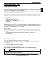
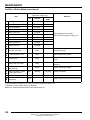
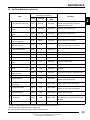
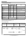
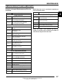
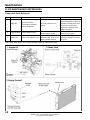
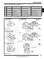
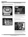
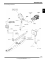
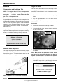
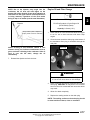
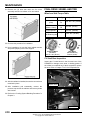
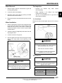
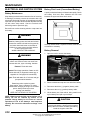
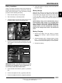
MAINTENANCE CHAPTER 2 MAINTENANCE PERIODIC MAINTENANCE CHART . . . . . . . . . . . . . . . . . . . . . . . . . . . . . . . . . . . . . . . . . 2.3 BREAK-IN PERIOD / MAINTENANCE CHART KEY . . . . . . . . . . . . . . . . . . . . . . . . . . . . 2.3 PRE-RIDE - 25 HOUR MAINTENANCE INTERVAL . . . . . . . . . . . . . . . . . . . . . . . . . . . . 2.4 25 - 100 HOUR MAINTENANCE INTERVAL . . . . . . . . . . . . . . . . . . . . . . . . . . . . . . . . . . 2.5 100 - 500 HOUR MAINTENANCE INTERVAL . . . . . . . . . . . . . . . . . . . . . . . . . . . . . . . . . 2.6 GREASE LUBRICATION POINTS . . . . . . . . . . . . . . . . . . . . . . . . . . . . . . . . . . . . . . . . . . 2.6 2 SERVICE PRODUCTS AND LUBRICANTS . . . . . . . . . . . . . . . . . . . . . . . . . . . . . . . . . . . 2.7 FLUID MAINTENANCE REFERENCES . . . . . . . . . . . . . . . . . . . . . . . . . . . . . . . . . . . . . . 2.8 GENERAL VEHICLE INSPECTION AND MAINTENANCE. . . . . . . . . . . . . . . . . . . . . . . 2.10 PRE-RIDE / DAILY INSPECTION . . . . . . . . . . . . . . . . . . . . . . . . . . . . . . . . . . . . . . . . . 2.10 FRAME, NUTS, BOLTS, AND FASTENERS . . . . . . . . . . . . . . . . . . . . . . . . . . . . . . . . . 2.10 SHIFT CABLE INSPECTION . . . . . . . . . . . . . . . . . . . . . . . . . . . . . . . . . . . . . . . . . . . . . 2.10 SHIFT CABLE ADJUSTMENT (XP / HD / CREW) . . . . . . . . . . . . . . . . . . . . . . . . . . . . . 2.10 SHIFT CABLE ADJUSTMENT (6X6) . . . . . . . . . . . . . . . . . . . . . . . . . . . . . . . . . . . . . . . 2.11 FUEL SYSTEM AND AIR INTAKE . . . . . . . . . . . . . . . . . . . . . . . . . . . . . . . . . . . . . . . . . 2.12 FUEL LINES / VENT LINES . . . . . . . . . . . . . . . . . . . . . . . . . . . . . . . . . . . . . . . . . . . . . . 2.12 FUEL PUMP / FUEL FILTERS . . . . . . . . . . . . . . . . . . . . . . . . . . . . . . . . . . . . . . . . . . . . 2.12 THROTTLE PEDAL INSPECTION . . . . . . . . . . . . . . . . . . . . . . . . . . . . . . . . . . . . . . . . . 2.12 THROTTLE FREEPLAY ADJUSTMENT . . . . . . . . . . . . . . . . . . . . . . . . . . . . . . . . . . . . 2.12 AIR FILTER SERVICE . . . . . . . . . . . . . . . . . . . . . . . . . . . . . . . . . . . . . . . . . . . . . . . . . . 2.13 ENGINE AIR INTAKE INSPECTION . . . . . . . . . . . . . . . . . . . . . . . . . . . . . . . . . . . . . . . 2.14 PVT AIR INTAKE INSPECTION . . . . . . . . . . . . . . . . . . . . . . . . . . . . . . . . . . . . . . . . . . . 2.14 AIR INTAKE EXPLODED VIEW . . . . . . . . . . . . . . . . . . . . . . . . . . . . . . . . . . . . . . . . . . . 2.15 ENGINE . . . . . . . . . . . . . . . . . . . . . . . . . . . . . . . . . . . . . . . . . . . . . . . . . . . . . . . . . . . . . . 2.16 COMPRESSION AND LEAKDOWN TEST. . . . . . . . . . . . . . . . . . . . . . . . . . . . . . . . . . . 2.16 BREATHER HOSE INSPECTION . . . . . . . . . . . . . . . . . . . . . . . . . . . . . . . . . . . . . . . . . 2.16 ENGINE OIL LEVEL . . . . . . . . . . . . . . . . . . . . . . . . . . . . . . . . . . . . . . . . . . . . . . . . . . . . 2.16 ENGINE OIL AND FILTER CHANGE . . . . . . . . . . . . . . . . . . . . . . . . . . . . . . . . . . . . . . . 2.17 EXHAUST PIPE . . . . . . . . . . . . . . . . . . . . . . . . . . . . . . . . . . . . . . . . . . . . . . . . . . . . . . . 2.18 TRANSMISSION AND GEARCASES . . . . . . . . . . . . . . . . . . . . . . . . . . . . . . . . . . . . . . . 2.19 2011 TRANSMISSION LUBRICATION (XP / HD / CREW) . . . . . . . . . . . . . . . . . . . . . . 2.19 2012 TRANSMISSION LUBRICATION (XP / HD / CREW) . . . . . . . . . . . . . . . . . . . . . . 2.20 TRANSMISSION LUBRICATION (6X6) . . . . . . . . . . . . . . . . . . . . . . . . . . . . . . . . . . . . . 2.21 FRONT GEARCASE LUBRICATION . . . . . . . . . . . . . . . . . . . . . . . . . . . . . . . . . . . . . . . 2.22 MID GEARCASE LUBRICATION (6X6) . . . . . . . . . . . . . . . . . . . . . . . . . . . . . . . . . . . . . 2.24 REAR GEARCASE LUBRICATION (6X6) . . . . . . . . . . . . . . . . . . . . . . . . . . . . . . . . . . . 2.25 COOLING SYSTEM. . . . . . . . . . . . . . . . . . . . . . . . . . . . . . . . . . . . . . . . . . . . . . . . . . . . . 2.26 COOLANT LEVEL INSPECTION . . . . . . . . . . . . . . . . . . . . . . . . . . . . . . . . . . . . . . . . . . 2.26 COOLANT STRENGTH / TYPE . . . . . . . . . . . . . . . . . . . . . . . . . . . . . . . . . . . . . . . . . . . 2.27 COOLING SYSTEM HOSES . . . . . . . . . . . . . . . . . . . . . . . . . . . . . . . . . . . . . . . . . . . . . 2.27 RADIATOR INSPECTION / CLEANING . . . . . . . . . . . . . . . . . . . . . . . . . . . . . . . . . . . . . 2.27 COOLANT DRAIN . . . . . . . . . . . . . . . . . . . . . . . . . . . . . . . . . . . . . . . . . . . . . . . . . . . . . 2.27 RADIATOR REMOVAL. . . . . . . . . . . . . . . . . . . . . . . . . . . . . . . . . . . . . . . . . . . . . . . . . . 2.28 FINAL DRIVE / WHEEL AND TIRE . . . . . . . . . . . . . . . . . . . . . . . . . . . . . . . . . . . . . . . . . 2.30 WHEEL AND HUB TORQUE TABLE . . . . . . . . . . . . . . . . . . . . . . . . . . . . . . . . . . . . . . . 2.30 CV SHAFT BOOT INSPECTION . . . . . . . . . . . . . . . . . . . . . . . . . . . . . . . . . . . . . . . . . . 2.30 WHEEL REMOVAL / INSTALLATION . . . . . . . . . . . . . . . . . . . . . . . . . . . . . . . . . . . . . . 2.31 TIRE INSPECTION. . . . . . . . . . . . . . . . . . . . . . . . . . . . . . . . . . . . . . . . . . . . . . . . . . . . . 2.31 TIRE PRESSURE . . . . . . . . . . . . . . . . . . . . . . . . . . . . . . . . . . . . . . . . . . . . . . . . . . . . . . 2.31 2.1 9923499 - 2011 / 2012 RANGER 800 Service Manual © Copyright 2011 Polaris Sales Inc. MAINTENANCE ELECTRICAL AND IGNITION SYSTEM . . . . . . . . . . . . . . . . . . . . . . . . . . . . . . . . . . . . . 2.32 BATTERY MAINTENANCE / FLUID LEVEL (CONVENTIONAL BATTERY) . . . . . . . . . 2.32 BATTERY REMOVAL. . . . . . . . . . . . . . . . . . . . . . . . . . . . . . . . . . . . . . . . . . . . . . . . . . . 2.32 BATTERY INSTALLATION. . . . . . . . . . . . . . . . . . . . . . . . . . . . . . . . . . . . . . . . . . . . . . . 2.33 BATTERY STORAGE. . . . . . . . . . . . . . . . . . . . . . . . . . . . . . . . . . . . . . . . . . . . . . . . . . . 2.33 BATTERY CHARGING. . . . . . . . . . . . . . . . . . . . . . . . . . . . . . . . . . . . . . . . . . . . . . . . . . 2.33 SPARK PLUG SERVICE . . . . . . . . . . . . . . . . . . . . . . . . . . . . . . . . . . . . . . . . . . . . . . . . 2.34 ENGINE TO FRAME GROUND . . . . . . . . . . . . . . . . . . . . . . . . . . . . . . . . . . . . . . . . . . . 2.34 STEERING . . . . . . . . . . . . . . . . . . . . . . . . . . . . . . . . . . . . . . . . . . . . . . . . . . . . . . . . . . . 2.35 TIE ROD END / STEERING INSPECTION . . . . . . . . . . . . . . . . . . . . . . . . . . . . . . . . . . 2.35 WHEEL TOE ALIGNMENT INSPECTION . . . . . . . . . . . . . . . . . . . . . . . . . . . . . . . . . . . 2.35 TOE ADJUSTMENT . . . . . . . . . . . . . . . . . . . . . . . . . . . . . . . . . . . . . . . . . . . . . . . . . . . . 2.36 SUSPENSION (STANDARD) . . . . . . . . . . . . . . . . . . . . . . . . . . . . . . . . . . . . . . . . . . . . . 2.37 SUSPENSION INSPECTION . . . . . . . . . . . . . . . . . . . . . . . . . . . . . . . . . . . . . . . . . . . . . 2.37 SPRING PRE-LOAD ADJUSTMENT . . . . . . . . . . . . . . . . . . . . . . . . . . . . . . . . . . . . . . . 2.37 SHOCK POSITION ADJUSTMENT . . . . . . . . . . . . . . . . . . . . . . . . . . . . . . . . . . . . . . . . 2.37 SUSPENSION (WALKER EVANS™) . . . . . . . . . . . . . . . . . . . . . . . . . . . . . . . . . . . . . . . 2.38 SPRING PRELOAD ADJUSTMENT. . . . . . . . . . . . . . . . . . . . . . . . . . . . . . . . . . . . . . . . 2.38 SHOCK COMPRESSION ADJUSTMENT . . . . . . . . . . . . . . . . . . . . . . . . . . . . . . . . . . . 2.38 BRAKE SYSTEM. . . . . . . . . . . . . . . . . . . . . . . . . . . . . . . . . . . . . . . . . . . . . . . . . . . . . . . 2.39 BRAKE FLUID INSPECTION . . . . . . . . . . . . . . . . . . . . . . . . . . . . . . . . . . . . . . . . . . . . . 2.39 BRAKE HOSE AND FITTING INSPECTION . . . . . . . . . . . . . . . . . . . . . . . . . . . . . . . . . 2.39 BRAKE PAD / DISC INSPECTION. . . . . . . . . . . . . . . . . . . . . . . . . . . . . . . . . . . . . . . . . 2.39 PARKING BRAKE CABLE ADJUSTMENT . . . . . . . . . . . . . . . . . . . . . . . . . . . . . . . . . . 2.40 PARKING BRAKE PAD INSPECTION . . . . . . . . . . . . . . . . . . . . . . . . . . . . . . . . . . . . . . 2.40 MAINTENANCE LOG . . . . . . . . . . . . . . . . . . . . . . . . . . . . . . . . . . . . . . . . . . . . . . . . . . . 2.41 2.2 9923499 - 2011 / 2012 RANGER 800 Service Manual © Copyright 2011 Polaris Sales Inc. MAINTENANCE PERIODIC MAINTENANCE CHART Periodic Maintenance Overview Inspection, adjustment and lubrication of important components are explained in the periodic maintenance chart. Inspect, clean, lubricate, adjust and replace parts as necessary. When inspection reveals the need for replacement parts, use genuine Pure Polaris parts available from your Polaris dealer. NOTE: Service and adjustments are critical. If you’re not familiar with safe service and adjustment procedures, have a qualified dealer perform these operations. Maintenance intervals in the following chart are based upon average riding conditions and an average vehicle speed of approximately 10 miles per hour. Vehicles subjected to severe use must be inspected and serviced more frequently. Severe Use Definition • Frequent immersion in mud, water or sand • Racing or race-style high RPM use • Prolonged low speed, heavy load operation • Extended idle • Short trip cold weather operation Pay special attention to the oil level. A rise in oil level during cold weather can indicate contaminants collecting in the oil sump or crankcase. Change oil immediately if the oil level begins to rise. Monitor the oil level, and if it continues to rise, discontinue use and determine the cause or see your dealer. Break-In Period The break-in period consists of the first 25 hours of operation, or the time it takes to use 14 gallons (53 liters) of fuel. Careful treatment of a new engine and drive components will result in more efficient performance and longer life for these components. • Drive vehicle slowly at first while varying the throttle position. Do not operate at sustained idle. • Pull only light loads. • Perform regular checks on fluid levels and other areas outlined on the daily pre-ride inspection checklist. • Change both the engine oil and filter after 25 hours or one month. • See “Owner’s Manual” for additional break-in information. Maintenance Chart Key The following symbols denote potential items to be aware of during maintenance: = CAUTION: Due to the nature of these adjustments, it is recommended this service be performed by an authorized Polaris dealer. = SEVERE USE ITEM: See information provided above. E = Emission Control System Service (California). NOTE: Inspection may reveal the need for replacement parts. Always use genuine Polaris parts. WARNING Improperly performing the procedures marked could result in component failure and lead to serious injury or death. Have an authorized Polaris dealer perform these services. 2.3 9923499 - 2011 / 2012 RANGER 800 Service Manual © Copyright 2011 Polaris Sales Inc. 2 MAINTENANCE Pre-Ride - 25 Hour Maintenance Interval Maintenance Interval (whichever comes first) Item Remarks Hours Calendar Miles (KM) Steering - Pre-Ride - Front Suspension Rear Suspension - Pre-Ride - - Pre-Ride - - Pre-Ride - Brake Fluid Level Brake Pedal Travel - Pre-Ride - - Pre-Ride - Brake Systems - Pre-Ride - Wheels / Fasteners - Pre-Ride - Frame Fasteners - Pre-Ride - Engine Oil Level - Pre-Ride - Air Filter / Pre-Filter - Daily - Inspect;clean often Air Box Sediment Tube - Daily - Drain deposits when visible Coolant Level - Daily - Check level daily, change coolant every 2 years Head Lamp / Tail Lamp - Daily - Check operation; apply dielectric grease if replacing - Weekly - Inspect; replace as needed 10 H Monthly 100 (160) Inspect periodically 20 H Monthly 200 (320) Check terminals; clean; test 25 H - - Tires E E E Air Filter, E Main Element Brake Pad Wear / Inspect Parking Brake Pads Battery Parking Brake Cable Adjustment Make adjustments as needed. See Pre-Ride Checklist on Page 2.10. Inspect; adjust tension after first 25 hours Perform these procedures more often for vehicles subjected to severe use. E Emission Control System Service (California) Have an authorized Polaris dealer perform these services. 2.4 9923499 - 2011 / 2012 RANGER 800 Service Manual © Copyright 2011 Polaris Sales Inc. MAINTENANCE 25 - 100 Hour Maintenance Interval Maintenance Interval (whichever comes first) Item Hours Remarks Miles (KM) Calendar 2 25 H Monthly 250 (400) Inspect level; change yearly; change demand drive fluid every 25 hours if exposed to extreme use 25 H Monthly 250 (400) Inspect level; change yearly 25 H Monthly 250 (400) Inspect level; change yearly 25 H Monthly 250 (400) Inspect level; change yearly 25 H Monthly 250 (400) Inspect; replace if necessary 25 H 1M - Perform a break-in oil change after the first 25 hours or one month of operation 50 H 3M 500 (800) Lubricate all grease fittings, pivots, cables, etc. 50 H 6M 500 (800) Inspect, lubricate, adjust Steering 50 H 6M 500 (800) Lubricate (if applicable) Front Suspension 50 H 6M 500 (800) Lubricate (if applicable) 50 H 6M 500 (800) Lubricate (if applicable) 50 H 6M 500 (800) Lubricate (if applicable) Throttle Cable / Throttle E Pedal 50 H 6M 500 (800) Inspect; adjust; lubricate; replace if necessary Throttle Body Air Intake Ducts / Flange 50 H 6M 500 (800) Inspect ducts for proper sealing/air leaks Drive Belt 50 H 6M 500 (800) Inspect; adjust; replace as needed Cooling System 50 H 6M 500 (800) Inspect coolant strength seasonally; pressure test system yearly 100 H 6M 1000 (1600) Inspect; adjust tension as needed Engine Oil Change 100 H 6M 1000 (1600) Perform a break-in oil change after the first 25 hours or one month of operation Oil Filter Change 100 H 6M 1000 (1600) Replace with oil change Fuel System E 100 H 12 M 1000 (1600) Check for leaks at tank cap, fuel lines, fuel pump, and fuel rail; replace fuel lines every two years. Radiator 100 H 12 M 1000 (1600) Inspect; clean external surfaces Front Gearcase Lubricant Mid Gearcase Lubricant (6x6) Rear Gearcase Lubricant (6x6) Transmission Lubricant Engine Breather E Filter (if equipped) Engine Oil Change E (Break-In Period) General Lubrication Shift Linkage Mid Suspension (6x6) Rear Suspension E Parking Brake Cable Adjustment E E Perform these procedures more often for vehicles subjected to severe use. E Emission Control System Service (California) Have an authorized Polaris dealer perform these services. 2.5 9923499 - 2011 / 2012 RANGER 800 Service Manual © Copyright 2011 Polaris Sales Inc. MAINTENANCE 100 - 500 Hour Maintenance Interval Maintenance Interval (whichever comes first) Item Remarks Hours Calendar Miles (Km) 100 H 12 M 1000 (1600) Inspect for leaks 100 H 12 M 1000 (1600) Inspect 100 H 12 M 1000 (1600) Inspect Spark Plug E 100 H 12 M 1000 (1600) Inspect; replace as needed Wiring 100 H 12 M 1000 (1600) Inspect for wear, routing, security; apply dielectric grease to connectors subjected to water, mud, etc. Clutches (Drive and Driven) 100 H 12 M 1000 (1600) Inspect; clean; replace worn parts Front Wheel Bearings 100 H 12 M 1000 (1600) Inspect; replace as needed Shocks 100 H - - Visually inspect shock seals Brake Fluid 200 H 24 M 2000 (3200) Change every two years (DOT 4) 300 H 36 M 3000 (4800) Clean out 500 H 12 M - Cooling Hoses Engine Mounts Exhaust Silencer / Pipe Spark Arrestor Shocks (Walker Evans) - Inspect periodically; adjust when parts are replaced - Adjust as needed Toe Adjustment Headlight Aim Change shock oil and replace seals Perform these procedures more often for vehicles subjected to severe use. E Emission Control System Service (California) Have an authorized Polaris dealer perform these services. Grease Lubrication Points Item Front Propshaft Yoke Recommended Lube Method Grease fittings Polaris Premium U-Joint Grease (3 pumps maximum) 2.6 9923499 - 2011 / 2012 RANGER 800 Service Manual © Copyright 2011 Polaris Sales Inc. Frequency Grease before long periods of storage, and after pressure washing or submerging the vehicle. MAINTENANCE SERVICE PRODUCTS AND LUBRICANTS Polaris Lubricants, Maintenance and Service Products Part No. Description Engine Lubricant NOTE: Each item can be purchased separately at your local Polaris dealer. Part No. Description Additives / Sealants / Thread Locking Agents / Misc. 2870791 Fogging Oil (12 oz. Aerosol) 2871950 Loctite™ Threadlock 242 (6 ml.) (12 count) 2876244 PS-4 Plus Performance Synthetic 4-Cycle Engine Oil (Quart) 2871326 Premium Carbon Clean (12 oz.) (12 count) 2876245 PS-4 Plus Performance Synthetic 4-Cycle Engine Oil (Gallon) 2870652 Fuel Stabilizer (16 oz.) (12 count) Gearcase / Transmission Lubricants 2872189 DOT 4 Brake Fluid (12 count) 2871557 Crankcase Sealant, 3-Bond 1215 (5 oz.) 2877922 Demand Drive Plus (Quart) 2877923 Demand Drive Plus (2.5 Gallon) 2878068 AGL Plus Gearcase Lubricant (1 Qt.) (12 Count) 2878069 AGL Plus Gearcase Lubricant (1 Gal.) (4 Count) 2878070 AGL Plus Gearcase Lubricant (2.5 Gal.) (2 Count) 2876160 ATV Angle Drive Fluid (Quart) (12 count) 2872276 ATV Angle Drive Fluid (2.5 Gallon) (2 Count) 2870465 Oil Pump for 1 Gallon Jug NOTE: The number count indicated by each part number in the table above indicates the number of units that are shipped with each order. Grease / Specialized Lubricants 2871322 Premium All Season Grease (3 oz. cartridge) (24 Count) 2871423 Premium All Season Grease (14 oz. cartridge) (10 Count) 2871460 Starter Drive Grease (12 Count) 2871515 Premium U-Joint Lube (3 oz.) (24 Count) 2871551 Premium U-Joint Lube (14 oz.) (10 Count) 2871312 Grease Gun Kit 2871329 Dielectric Grease (Nyogel™) Coolant 2871323 60/40 Coolant (Gallon) (6 Count) 2871534 60/40 Coolant (Quart) (12 Count) 2.7 9923499 - 2011 / 2012 RANGER 800 Service Manual © Copyright 2011 Polaris Sales Inc. 2 MAINTENANCE FLUID MAINTENANCE REFERENCES Component Quick Reference III. # 1 Item Engine Oil Lube Rec. Method Frequency* Polaris PS-4 Plus Performance Synthetic 4-Cycle Engine Oil Add oil to proper level on dipstick Change after 1st month or first 25 hours of operation, 100 hours thereafter; Change more often (25 hours) in severe duty conditions or short trip cold weather operation Maintain coolant level in coolant reservoir bottle. Check level daily, change coolant every 2 years 2 Engine Coolant Polaris 60/40 Coolant 3 Brake Fluid Maintain fluid level between Polaris DOT 4 Brake Fluid “MAX and “MIN” lines on the master cylinder reservoir Check level during pre-ride inspection; change fluid every two years * More often under severe use, such as operated in water or under severe loads. Radiator Cap 2.8 9923499 - 2011 / 2012 RANGER 800 Service Manual © Copyright 2011 Polaris Sales Inc. MAINTENANCE Component Quick Reference, Continued..... III. # Item Lube Rec. Method Frequency* 4 Front Gearcase Polaris Demand Drive Plus Add lubricant until it is visible at the fill hole threads Check level every 25 hours; change according to intervals 5 Mid Gearcase Polaris ATV Angle Drive Fluid (ADF) Add lubricant until it is visible at the fill hole threads Check level every 25 hours; change fluid yearly 6 Rear Gearcase Polaris ATV Angle Drive Fluid (ADF) Add lubricant until it is visible at the fill hole threads Check level every 25 hours; change fluid yearly 7 Transmission Polaris AGL Plus Gearcase Lubricant Add lubricant until it is visible Check level every 25 hours; at the check plug hole threads change lubricant yearly * More often under severe use, such as operated in water or under severe loads. 2.9 9923499 - 2011 / 2012 RANGER 800 Service Manual © Copyright 2011 Polaris Sales Inc. 2 MAINTENANCE GENERAL VEHICLE INSPECTION AND MAINTENANCE Pre-Ride / Daily Inspection Perform the following pre-ride inspection daily, and when servicing the vehicle at each scheduled maintenance. • Tires - check condition and pressures • Fuel tank - fill tank to proper level Shift Cable Adjustment (XP / HD / CREW) NOTE: The shift cable should be adjusted at the rear adjustment point located near the transmission. If adjustment is needed beyond that, remove the dash panel to access the shift cable adjustment point located underneath the shift lever. 1. Place gear selector in neutral. Make sure the transmission bell crank is engaged in the neutral position detents. • All brakes - check operation, fluid level and adjustment (includes parking brake) Adjustment Point • Throttle - check for free operation and closing • Headlight/Taillight/Brakelight - check operation of all indicator lights, instrument cluster and switches • Ignition switch - check for proper function • Wheels - check for tightness of wheel nuts and axle nuts; check to be sure axle nuts are secured by cotter pins • Air cleaner element - check for dirt; clean or replace • Steering - check for free operation noting any unusual looseness in any area • Loose parts - visually inspect vehicle for any damaged or loose nuts, bolts or fasteners • Engine coolant - check for proper level at the recovery bottle • Check all suspension components for wear or damage Neutral Position 2. Locate the shift cable adjustment point at the engineto-transmission mount bracket. 3. With two open-end wrenches, loosen the outside jam nut counterclockwise. Turn the outside jam nut 1 1/2 turns. Inside Jam Nut Frame, Nuts, Bolts, and Fasteners Periodically inspect the torque of all fasteners in accordance with the maintenance schedule. Check that all cotter pins are in place. Refer to specific fastener torques listed in each chapter. Shift Cable Inspection Outside Jam Nut Shift cable adjustment is necessary when symptoms include: 4. After turning the outside jam nut 1 1/2 turns. Hold the outside jam nut with a wrench and tighten the inside jam nut clockwise, until it is tight against the bracket. • Noise on deceleration • Inability to engage a gear • Excessive gear clash (noise) • Gear selector is moving out of desired range Inspect shift cable, clevis pins, and pivot bushings and replace if worn or damaged. 5. Repeat Step 3 and Step 4 until the proper adjustment is made to the shift cable. 6. Use this procedure to loosen or tighten the shift linkage cable as needed. 2.10 9923499 - 2011 / 2012 RANGER 800 Service Manual © Copyright 2011 Polaris Sales Inc. MAINTENANCE Shift Cable Adjustment (6x6) NOTE: The shift cable should be adjusted at the rear adjustment point located near the transmission. If adjustment is needed beyond that, remove the dash panel to access the shift cable adjustment point located underneath the shift lever. 2 1. Place gear selector in neutral. Make sure the transmission bell crank is engaged in the neutral position detents. Adjustment Point Neutral Position 2. Locate the shift cable adjustment point attached to the frame in front of the transmission. 3. With two open-end wrenches loosen the outside jam nut counterclockwise. Turn the outside jam nut 1 1/2 turns. Outside Jam Nut Inside Jam Nut 4. After turning the outside jam nut 1 1/2 turns. Hold the outside jam nut with a wrench and tighten the inside jam nut clockwise, until it is tight against the bracket. 5. Repeat Step 3 and Step 4 until the proper adjustment is made for the transmission cable. 6. Use this procedure to loosen or tighten the shift linkage cable as needed. 2.11 9923499 - 2011 / 2012 RANGER 800 Service Manual © Copyright 2011 Polaris Sales Inc. MAINTENANCE FUEL SYSTEM AND AIR INTAKE Fuel Pump / Fuel Filters Fuel System The RANGER 800 EFI engine uses a serviceable, highvolume, high-pressure, fuel pump that includes a preliminary filter and an internal fine filter located before the pump regulator. WARNING Gasoline is extremely flammable and explosive under certain conditions. Always stop the engine and refuel outdoors or in a well ventilated area. Do not smoke or allow open flames or sparks in or near the area where refueling is performed or where gasoline is stored. Do not overfill the tank. Do not fill the tank neck. If you get gasoline in your eyes or if you swallow gasoline, seek medical attention immediately. If you spill gasoline on your skin or clothing, immediately wash it off with soap and water and change clothing. Never start the engine or let it run in an enclosed area. Engine exhaust fumes are poisonous and can result in loss of consciousness or death in a short time. Never drain the fuel when the engine is hot. Severe burns may result. Fuel Lines 1. Check fuel lines for signs of wear, deterioration, damage or leakage. Replace if necessary. 2. Be sure fuel lines are routed properly and secured with cable ties. CAUTION: Make sure lines are not kinked or pinched. 3. Replace all fuel lines every two years. Vent Lines 1. Check fuel tank vent lines for signs of wear, deterioration, damage or leakage. Replace every two years. 2. Be sure vent lines are routed properly and secured with cable ties. IMPORTANT: Ensure lines are not kinked or pinched. NOTE: Neither filter is servicable individually. Must replace the fuel pump as an assembly. NOTE: Refer to Chapter 4 for fuel pump replacement and all other information related to the EFI System. Throttle Pedal Inspection If the throttle pedal has excessive play due to cable stretch or cable misadjustment, it will cause a delay in throttle speed and the throttle may not open fully. If the throttle pedal has no play, it may be hard to control, and the idle speed may be erratic. Check the throttle pedal play periodically in accordance with the Periodic Maintenance Chart and adjust the play if necessary. Throttle Freeplay Adjustment Inspection 1. Apply the parking brake. 2. Put the gear shift lever in the N (Neutral) position. 3. Start the engine, and warm it up thoroughly. 4. Measure the distance the throttle pedal moves before the engine begins to pick up speed. Free play should be 1/16” - 1/8” (1.5 - 3 mm). 2.12 9923499 - 2011 / 2012 RANGER 800 Service Manual © Copyright 2011 Polaris Sales Inc. MAINTENANCE Adjustment Air Filter Service 1. Remove the lower seat base. It is recommended the air filter be replaced annually. When riding in extremely dusty or wet conditions, or at wide open throttle for extended periods, replacement is required more often. The filter should be inspected periodically (see “Periodic Maintenance Chart”). 2. Locate the throttle cable adjustment at the throttle body. Throttle Cable Adjuster Removal 1. Lift the rear cargo box to access the airbox cover. 3. Slide back the cable adjuster boot. 4. Using a 14 mm open-end wrench, loosen the adjustment jam nut. Using a 12 mm open-end wrench, move the cable adjuster until 1/16” to 1/8” (1.5 - 3 mm) of freeplay is achieved at the throttle pedal. Boot Jam Nut Airbox Cover 2. Unhook the (4) clips from airbox cover and remove cover. Inspect the cover seal. It should adhere tightly to the cover. 3. Remove air filter assembly by using a pulling/twisting motion. Be sure not to damage the filter element. 4. Inspect the air filter element and replace if necessary. Do not attempt to clean the air filter. IMPORTANT: If the filter has been soaked with fuel or oil it must be replaced. Do not attempt to wash the air filter. If cleaning is required, replace the filter. Adjuster NOTE: While adjusting, lightly move the throttle pedal in and out. 5. Re-tighten the jam nut after final adjustment is made. 6. Apply a small amount of grease to the inside of the boot and slide it over the cable adjuster to its original position. 7. Reinstall the lower seat base. 8. Start the engine. 9. Disengage the parking brake and field test unit to ensure proper throttle operation. 2.13 9923499 - 2011 / 2012 RANGER 800 Service Manual © Copyright 2011 Polaris Sales Inc. 2 MAINTENANCE Installation Engine Air Intake Inspection 1. Clean airbox of any oil or water deposits and apply a small amount of grease to the sealing surfaces of the filter. Verify plastic sealing ring is installed on filter sealing area. 1. Open the hood to access the engine intake air baffle box. Plastic Ring 2. Remove the filter element from the baffle box. Filter Element . Apply Polaris All Purpose Grease to inner sealing area 2. Reinstall the air filter cover into the airbox container. Align tab and notch for proper fit. Be sure the filter cover fits tightly to the air box and engage the 4 clips onto the airbox. 3. If the filter element is dirty, clean it with a high flash point solvent, followed by hot soapy water. Rinse and dry the filter element thoroughly. Inspect element for tears or damage. Replace if necessary. 4. Reinstall the filter element into the air baffle box. PVT Air Intake Inspection 1. Lift the cargo box to access the PVT air intake baffle box. 2. Remove the filter element from the baffle box. Filter Element Be sure tab and notch are in alignment 3. If the filter element is dirty, clean it with a high flash point solvent, followed by hot soapy water. Rinse and dry the filter element thoroughly. Inspect element for tears or damage. Replace if necessary. 4. Reinstall the filter element into the air baffle box. 2.14 9923499 - 2011 / 2012 RANGER 800 Service Manual © Copyright 2011 Polaris Sales Inc. MAINTENANCE Air Intake Exploded View 2 2.15 9923499 - 2011 / 2012 RANGER 800 Service Manual © Copyright 2011 Polaris Sales Inc. MAINTENANCE ENGINE Engine Oil Level Compression and Leakdown Test The twin cylinder domestic engine is a wet-sump engine, meaning the oil is contained in the bottom of the crankcase. To check the oil level follow the procedure listed below: NOTE: This engine does NOT have decompression components. Compression readings will vary in proportion to cranking speed during the test. Average compression (measured) is about 165-185 psi during a compression test. A smooth idle generally indicates good compression. Low engine compression is rarely a factor in running condition problems above idle speed. Abnormally high compression can be caused by carbon deposits in the combustion chamber or worn, damaged exhaust cam lobes. Inspect camshaft and combustion chamber if compression is abnormally high. A cylinder leakdown test is the best indication of engine condition. Follow manufacturer's instructions to perform a cylinder leakage test (never use high pressure leakage testers, as crankshaft seals may dislodge and leak). 1. Set machine on a level surface and set the parking brake. 2. Stop the engine and allow it to cool down before removing the dipstick. IMPORTANT: Do not run the machine and then check the dipstick. 3. Remove the seat base and storage container. 4. Unlock the dipstick lever. Remove dipstick and wipe dry with a clean cloth. Dipstick Lever Lock Cylinder Compression Standard: 165-185 PSI Cylinder Leakdown Service Limit 15% (Inspect for cause if test exceeds 15%) Breather Hose Inspection The engine is equipped with a breather hose (A). Inspect the breather hose for possible kinks or wear. The hose is formed for a proper fit. Follow the breather hose from the side of the airbox to the engine valve cover. 5. Reinstall dipstick and push it into place. Do not lock the dipstick. NOTE: Make certain the dipstick is inserted all the way into the filler tube to keep the angle and depth of dipstick consistent. When reinstalling the dipstick, make certain to seat the lever lock. 6. Remove dipstick and check to see that the oil level is in the SAFE range. Add oil as indicated by the level on the dipstick. Do not overfill (see NOTE below!). Maintain Oil Level In SAFE Range A DO NOT Overfill the Engine NOTE: Make sure line is not kinked or pinched. 2.16 9923499 - 2011 / 2012 RANGER 800 Service Manual © Copyright 2011 Polaris Sales Inc. MAINTENANCE NOTE: Due to the dipstick entry angle into the crankcase, the oil level will read higher on the bottom side of the dipstick. Proper level indication is determined on the upper surface of the dipstick as it is being removed, regardless of the level marks being on top or on bottom (see the next illustration). Dipstick Engine Oil and Filter Change = 2 Recommended Engine Oil: PS-4 Plus Synthetic 4-Cycle Engine Oil (PN 2876244) (Quart) Capacity: 2 Quarts (1.9 L) Always read top side of dipstick to properly check oil level in crankcase 1. Place vehicle on a level surface and allow the engine to run for two to three minutes until warm. Stop engine. 2. Clean the area around the drain plug at the bottom of the crankcase. Drain plug is accessible through the skid plate. NOTE: A rising oil level between checks in cool weather driving can indicate contaminants such as gas or moisture collecting in the crankcase. If the oil level is over the full mark, change the oil immediately. Drain Plug 7. Reinstall the dipstick and lock the lever. WARNING Personal injury can occur when handling used oil. Hot oil can cause burns or skin damage. 3. Place a drain pan beneath the crankcase and remove drain plug. CAUTION: Oil may be hot. Do not allow hot oil to come into contact with skin as serious burns may result. 4. Allow oil to drain completely. 5. Replace the sealing washer on the drain plug. NOTE: The sealing surface on the drain plug should be clean and free of burrs, nicks or scratches. 2.17 9923499 - 2011 / 2012 RANGER 800 Service Manual © Copyright 2011 Polaris Sales Inc. MAINTENANCE 6. Reinstall drain plug and torque to specification. 14. Place gear selector in neutral and set parking brake. 15. Start the engine and let it idle for one to two minutes. Stop the engine and inspect for leaks. =T Engine Crankcase Drain Plug: 16 ± 2 ft. lbs. (21.7 ± 2.7 Nm) 7. Remove the lower seat base. 16. Re-check the oil level on the dipstick and add oil as necessary to bring the level to the upper mark on the dipstick. 17. Dispose of used oil and oil filter properly. 8. Remove the storage container located under the driver’s side of the seat. 9. Place shop towels beneath oil filter. Using Oil Filter Wrench (PU-50105), turn the filter counter-clockwise to remove it. Exhaust Pipe WARNING Do not perform clean out immediately after the engine has been run, as the exhaust system becomes very hot. Serious burns could result from contact with exhaust components. To reduce fire hazard, make sure that there are no combustible materials in the area when purging the spark arrestor. Wear eye protection. Do not stand behind or in front of the vehicle while purging the carbon from the spark arrestor. Never run the engine in an enclosed area. Exhaust contains poisonous carbon monoxide gas. Do not go under the machine while it is inclined. Set the hand brake and block the wheels to prevent roll back. Failure to heed these warnings could result in serious personal injury or death. Oil Filter Oil Filter Wrench: PU-50105: 2.5” (64 mm) 10. Using a clean, dry cloth, clean filter sealing surface on crankcase. 11. Lubricate O-ring on new oil filter with a film of fresh engine oil. Check to make sure the O-ring is in good condition. The exhaust pipe must be periodically purged of accumulated carbon as follows: 1. Remove the clean out plug(s) located on the bottom of the muffler as shown below. 12. Install new filter and turn by hand until filter gasket contacts the sealing surface, then turn an additional 1/2 turn. Clean Out Plug =T Oil Filter Torque: Turn by hand until filter gasket contacts sealing surface, then turn an additional 1/2 turn. 2. Set the parking brake and start the engine. Purge accumulated carbon from the system by momentarily revving the engine several times. 13. Remove the dipstick and fill the sump with 2 quarts (1.9 L) of Polaris PS-4 Plus Synthetic Engine Oil (PN 2876244). 2.18 9923499 - 2011 / 2012 RANGER 800 Service Manual © Copyright 2011 Polaris Sales Inc. MAINTENANCE 3. If some carbon is expelled, cover the exhaust outlet and lightly tap on the pipe around the clean out plugs with a rubber mallet while revving the engine several more times. TRANSMISSION AND GEARCASES 2011 Transmission Lubrication (XP / HD / CREW) NOTE: It is important to follow the transmission maintenance intervals described in the Periodic Maintenance Chart. Regular fluid level inspections should be performed as well. The transmission lubricant level should be checked and changed in accordance with the maintenance schedule. • Be sure vehicle is positioned on a level surface when checking or changing the lubricant. 4. If particles are still suspected to be in the muffler, back the machine onto an incline so the rear of the machine is one foot higher than the front. Set the parking brake, block the wheels and repeat Steps 2 and 3. • Check vent hose to be sure it is routed properly and unobstructed. Transmission Lubricant Level Check (2011) The fill plug is located on the right side of the transmission. Access the fill plug from the rear right-hand side of the vehicle. Maintain the fluid level even with the bottom threads of the fill plug hole. 1. Position vehicle on a level surface. 2. Remove the fill plug and check the lubricant level. 5. If particles are still suspected to be in the muffler, drive the machine onto the incline so the front of the machine is one foot higher than the rear. Set the parking brake, block the wheels and repeat Steps 2 and 3. 6. Repeat steps 2 through 5 until no more particles are expelled when the engine is revved. 7. Stop the engine and allow the arrestor to cool. 8. Reinstall the clean out plugs. 3. If lubricant level is not even with bottom threads, add recommended lubricant as needed. Do not overfill. 4. Reinstall the fill plug and torque to specification. =T Drain / Fill Plug: 10-14 ft. lbs. (14-19 Nm) 2.19 9923499 - 2011 / 2012 RANGER 800 Service Manual © Copyright 2011 Polaris Sales Inc. 2 MAINTENANCE Transmission Lubricant Change (2011) The drain plug is located on the right side of the transmission. Access the drain plug from the rear righthand side of the vehicle. 1. Remove the fill plug (refer to “Transmission Lubricant Level Check”). 2. Place a drain pan under the transmission drain plug. 3. Remove the drain plug and allow lubricant to drain completely. 2012 Transmission Lubrication (XP / HD / CREW) NOTE: It is important to follow the transmission maintenance intervals described in the Periodic Maintenance Chart. Regular fluid level inspections should be performed as well. The transmission lubricant level should be checked and changed in accordance with the maintenance schedule. • Be sure vehicle is positioned on a level surface when checking or changing the lubricant. • Check vent hose to be sure it is routed properly and unobstructed. Transmission Lubricant Level Check (2012) The fill plug is located at the rear of the transmission. The check plug is located on the right side of the transmission. Maintain the fluid level even with the bottom threads of the check plug hole. 1. Position vehicle on a level surface. 2. Remove the check plug and check the lubricant level. 4. Clean the drain plug magnetic surface. Reinstall drain plug with a new O-ring and torque to specification. 5. Add the recommended amount of lubricant through the fill plug hole. Maintain the lubricant level at the bottom of the fill plug hole when filling the transmission. Do not overfill. = Recommended Transmission Lubricant: AGL Plus (PN 2878068) (Quart) Capacity: 33.8 oz. (1000 ml) 6. Reinstall fill plug with a new O-ring and torque to specification. =T 3. If lubricant level is not even with the bottom threads, remove the fill plug and add the recommended lubricant as needed. Do not overfill. 4. Reinstall the fill plug and check plug. Torque the plugs to specification. Drain / Fill Plug: 10-14 ft. lbs. (14-19 Nm) =T 7. Check for leaks. Dispose of used lubricant properly. Fill / Check Plug: 10-14 ft. lbs. (14-19 Nm) 2.20 9923499 - 2011 / 2012 RANGER 800 Service Manual © Copyright 2011 Polaris Sales Inc. MAINTENANCE Transmission Lubricant Change (2012) Transmission Lubrication (6x6) The drain plug is located on the bottom of the transmission. Access the drain plug through the skid plate. NOTE: It is important to follow the transmission maintenance intervals described in the Periodic Maintenance Chart. Regular fluid level inspections should be performed as well. 1. Remove the fill plug. 2. Place a drain pan under the transmission drain plug. 3. Remove the drain plug and allow lubricant to drain completely. The transmission lubricant level should be checked and changed in accordance with the maintenance schedule. • Be sure vehicle is positioned on a level surface when checking or changing the lubricant. • Check vent hose to be sure it is routed properly and unobstructed. Transmission Lubricant Level Check The fill plug is located on the right side of the transmission. Access the fill plug from the rear right-hand side of the vehicle. Maintain the fluid level even with the bottom threads of the fill plug hole. 1. Position vehicle on a level surface. 2. Remove the fill plug and check the lubricant level. 4. Clean the drain plug magnetic surface. Reinstall drain plug with a new O-ring and torque to specification. 5. Remove the check plug. 6. Add the recommended amount of lubricant through the fill plug hole. Maintain the lubricant level at the bottom of the check plug hole when filling the transmission. Do not overfill (refer to “Transmission Lubricant Level Check”). = Recommended Transmission Lubricant: AGL Plus (PN 2878068) (Quart) Capacity: 33.8 oz. (1000 ml) 7. Reinstall fill plug and check plug with new O-rings. Torque the plugs to specification. 3. If lubricant level is not even with the bottom threads, add the recommended lubricant as needed. Do not overfill. 4. Reinstall the fill plug and torque to specification. =T =T Fill / Check / Drain Plug: 10-14 ft. lbs. (14-19 Nm) Drain / Fill Plug: 10-14 ft. lbs. (14-19 Nm) 8. Check for leaks. Dispose of used lubricant properly. 2.21 9923499 - 2011 / 2012 RANGER 800 Service Manual © Copyright 2011 Polaris Sales Inc. 2 MAINTENANCE Transmission Lubricant Change Front Gearcase Lubrication Access the drain plug on the right-hand side of the vehicle through the skid plate. NOTE: It is important to follow the front gearcase maintenance intervals described in the Periodic Maintenance Chart. Regular fluid level inspections should be performed as well. 1. Remove the fill plug (refer to “Transmission Lubricant Level Check”). 2. Place a drain pan under the transmission drain plug. 3. Remove the drain plug and allow lubricant to drain completely. The front gearcase fluid level should be checked and changed in accordance with the maintenance schedule. • Be sure vehicle is positioned on a level surface when checking or changing the fluid. • Check vent hose to be sure it is routed properly and unobstructed. Front Gearcase Fluid Level Check The fill plug is located on the front left side of the front gearcase. Access the fill plug from the front of the vehicle. Maintain the fluid level even with the bottom threads of the fill plug hole. 1. Position vehicle on a level surface. 2. Begin by removing the front bumper to gain access to the gearcase fill plug. 3. Remove the (2) T27 Torx-head screws retaining the fascia screen and remove the screen. 4. Clean the drain plug magnetic surface. Reinstall drain plug with a new O-ring and torque to specification. 5. Add the recommended amount of lubricant through the fill plug hole. Maintain the lubricant level at the bottom of the fill plug hole when filling the transmission. Do not overfill. = Recommended Transmission Lubricant: AGL Plus (PN 2878068) (Quart) Capacity: 43.6 oz. (1290 ml) 6. Reinstall fill plug with a new O-ring and torque to specification. =T 4. Remove the (3) bolts from the lower portion of the bumper. 5. Remove the fasteners from each side of the upper portion of the bumper. 6. Carefully remove the bumper from the vehicle. Drain / Fill Plug: 10-14 ft. lbs. (14-19 Nm) 7. Check for leaks. Dispose of used lubricant properly. 2.22 9923499 - 2011 / 2012 RANGER 800 Service Manual © Copyright 2011 Polaris Sales Inc. MAINTENANCE 7. Remove the fill plug and check the fluid level. 4. Clean the drain plug magnetic surface. 5. Reinstall drain plug with a new O-ring and torque to specification. 6. Add the recommended amount of fluid through the fill hole. Maintain the fluid level even with the bottom threads of the fill plug hole. = Recommended Front Gearcase Fluid: Polaris Demand Drive Plus (PN 2877922) (Quart) Capacity: 9 oz. (265 ml) 8. If fluid level is not even with the bottom threads, add the recommended fluid as needed. Do not overfill. 7. Reinstall fill plug with a new O-ring and torque to specification. 9. Reinstall the fill plug and torque to specification. =T =T Drain / Fill Plug: 8-10 ft. lbs. (11-14 Nm) Front Gearcase Fluid Change: Drain / Fill Plug: 8-10 ft. lbs. (11-14 Nm) 8. Check for leaks. Dispose of used fluid properly. 9. Reinstall the front bumper. The drain plug is located on the bottom side of the front gearcase. Access the drain plug through the skid plate. 1. Remove the fill plug (refer to “Front Gearcase Fluid Level Check”). 2. Place a drain pan under the front gearcase drain plug. 3. Remove the drain plug and allow fluid to drain completely. 10. Install the fasteners on each side of the upper portion of the bumper. Torque fasteners to 30 ft. lbs. (41 Nm). 11. Install the (3) bolts in the lower portion of the bumper. Torque bolts to 14 ft. lbs. (19 Nm). 12. Install the (2) T27 Torx-head screws retaining the fascia screen. Torque screws to 4-6 ft. lbs. (6-8 Nm). 2.23 9923499 - 2011 / 2012 RANGER 800 Service Manual © Copyright 2011 Polaris Sales Inc. 2 MAINTENANCE Mid Gearcase Lubrication (6x6) NOTE: It is important to follow the mid gearcase maintenance intervals described in the Periodic Maintenance Chart. Regular fluid level inspections should be performed as well. The gearcase lubricant level should be checked and changed in accordance with the maintenance schedule. • Be sure vehicle is level with parking brake on before proceeding. • Check vent hose to be sure it is routed properly and unobstructed. Mid Gearcase Lubricant Level Check: 5. Add the recommended amount of lubricant through the fill hole. Maintain the lubricant level even with the bottom threads of the fill plug hole. = Recommended Mid Gearcase Lubricant: ATV Angle Drive Fluid (PN 2876160) Capacity: 6.75 oz. (200 ml) 6. Reinstall fill plug and torque to specification. 7. Check for leaks. Dispose of used lubricant properly. The fill plug is located on the left side of the mid gearcase. Maintain the lubricant level even with the bottom threads of the fill plug hole. Make sure vent is unobstructed Side View 1. Position the vehicle on a level surface. 2. Remove the fill plug and check the lubricant level (see “Side View”). 3. If lubricant level is not even with the bottom threads, add the recommended lubricant as needed. Do not overfill. 4. Reinstall fill plug and torque to specification. =T Fill Plug: 14 ft. lbs. (19 Nm) Fill to bottom of fill plug hole threads: 6.75 oz. Mid Gearcase Lubricant Change: The drain plug is located on the bottom right side of the mid gearcase. Access the drain plug through the skid plate. Bottom View 1. Remove the fill plug (refer to “Mid Gearcase Lubricant Level Check”). 2. Place a drain pan under the mid gearcase drain plug. 3. Remove the drain plug and allow the lubricant to drain completely (see “Bottom View”). 4. Clean and reinstall drain plug. Torque to specification. =T Drain Plug: 14 ft. lbs. (19 Nm) Drain Plug 14 ft. lbs. (19 Nm) 2.24 9923499 - 2011 / 2012 RANGER 800 Service Manual © Copyright 2011 Polaris Sales Inc. Fill Plug 14 ft. lbs. (19 Nm) MAINTENANCE Rear Gearcase Lubrication (6x6) Rear Gearcase Lubricant Change: NOTE: It is important to follow the rear gearcase maintenance intervals described in the Periodic Maintenance Chart. Regular fluid level inspections should be performed as well. The drain plug is located on the bottom right side of the rear gearcase. Access the drain plug from the rear of the vehicle through the skid plate. The rear gearcase lubricant level should be checked and changed in accordance with the maintenance schedule. • Be sure vehicle is positioned on a level surface when checking or changing the lubricant. • Check vent hose to be sure it is routed properly and unobstructed. 1. Remove the fill plug (refer to “Rear Gearcase Lubricant Level Check”). 2. Place a drain pan under the rear gearcase drain plug. 3. Remove the drain plug and allow the lubricant to drain completely. Rear Gearcase Lubricant Level Check: The fill plug is located on the right side of the rear gearcase. Maintain the lubricant level even with the bottom threads of the fill plug hole. 1. Position the vehicle on a level surface. 2. Remove the fill plug and check the lubricant level. 4. Clean the drain plug magnetic surface. 5. Reinstall drain plug with a new O-ring and torque to specification. =T Drain Plug: 30-45 in. lbs. (3-5 Nm) 3. If lubricant level is not even with the bottom threads, add the recommended lubricant as needed. Do not overfill. 6. Add the recommended amount of lubricant through the fill hole. Maintain the lubricant level even with the bottom threads of the fill plug hole. 4. Reinstall fill plug and torque to specification. =T Fill Plug: 40-50 ft. lbs. (54-68 Nm) = Recommended Rear Gearcase Lubricant: ATV Angle Drive Fluid (PN 2876160) Capacity: 18 oz. (532 ml) 7. Reinstall fill plug with a new O-ring and torque to specification. 8. Check for leaks. Dispose of used lubricant properly. 2.25 9923499 - 2011 / 2012 RANGER 800 Service Manual © Copyright 2011 Polaris Sales Inc. 2 MAINTENANCE COOLING SYSTEM 2. Check the coolant level in the recovery bottle, located on the ride side of the machine. The coolant level must be maintained between the “MAX” and “MIN” levels indicated on the recovery bottle Liquid Cooling System Overview The engine coolant level is controlled or maintained by the recovery system. The recovery system components are the recovery bottle, radiator filler neck, radiator pressure cap and connecting hose. Recovery Bottle MAX As coolant operating temperature increases, the expanding (heated) excess coolant is forced out of the radiator past the pressure cap and into the recovery bottle. As engine coolant temperature decreases the contracting (cooled) coolant is drawn back up from the tank past the pressure cap and into the radiator. MIN NOTE: Some coolant level drop on new machines is normal as the system is purging itself of trapped air. Observe coolant levels often during the break-in period. Overheating of engine could occur if air is not fully purged from system. Polaris Premium 60/40 coolant is already premixed and ready to use. Do not dilute with water. Coolant Level Inspection 3. If the coolant level is below the “MIN” mark, open the hood to access the radiator pressure cap and recovery bottle cap. NOTE: If overheating is evident, allow system to cool completely and check coolant level in the radiator and inspect for signs of trapped air in system. The recovery bottle and radiator pressure cap are located under the hood. WARNING Never remove the pressure cap when the engine is warm or hot. Escaping steam can cause severe burns. The engine must be cool before removing the pressure cap. Recovery Bottle Radiator Cap 4. Remove the pressure cap. Using a funnel, add coolant to the top of the radiator filler neck. 5. Reinstall the pressure cap. NOTE: Use of a non-standard pressure cap will not allow the recovery system to function properly. 6. Remove the recovery bottle cap. With the engine at operating temperature, the coolant level should be between the “MAX” and “MIN” marks on the recovery bottle. If not, perform the following: 1. Position the vehicle on a level surface 7. Fill the recovery bottle to the “MAX” mark with Polaris Premium 60/40 Anti-Freeze/Coolant or a 50/50 mixture of antifreeze/coolant and distilled water as required for freeze protection in your area. 8. Reinstall the recovery bottle cap. 9. If coolant was required, start engine and check for leaks. Make sure radiator fins are clean to prevent overheating. 2.26 9923499 - 2011 / 2012 RANGER 800 Service Manual © Copyright 2011 Polaris Sales Inc. MAINTENANCE Coolant Strength / Type Radiator Inspection / Cleaning Test coolant strength by using an antifreeze hydrometer. 1. Check radiator air passages for restrictions or damage. 2 Antifreeze Hydrometer • A 50/50 or 60/40 mixture of antifreeze and distilled water will provide the optimum cooling, corrosion protection, and antifreeze protection. • Do not use tap water, straight antifreeze, or straight water in the system. Tap water contains minerals and impurities which build up in the system. Straight water or antifreeze may cause the system to freeze, corrode, or overheat. = 2. Carefully straighten any bent radiator fins. Recommended Anti-Freeze/Coolant: Polaris 60/40 Anti-Freeze/Coolant (PN 2871534) (Quart) 3. Remove any obstructions with compressed air or low pressure water. CAUTION Cooling System Hoses 1. Inspect all hoses for cracks, deterioration, abrasion or leaks. Replace if necessary. Washing the vehicle with a high-pressure washer could damage the radiator fins and impair the radiators effectiveness. Use of a highpressure washer is not recommended. Coolant Drain 1. Remove the push rivets and front LH wheel well panel to access the lower coolant hose at the radiator. 2. Place a suitable drain pan under the LH side of the radiator. 3. Allow the vehicle to cool down if recently operated. WARNING Never remove the pressure cap when the engine is warm or hot. Escaping steam can cause severe burns. The engine must be cool before removing the pressure cap. 2. Check tightness of all hose clamps. CAUTION Do not over-tighten hose clamps at radiator, or radiator fitting may distort. Radiator hose clamp torque is 36 in. lbs. (4 Nm). 4. Open the hood and slowly open the radiator pressure cap to relieve system pressure. 5. Remove the lower coolant hose and drain the coolant from the radiator and hose. Allow the coolant to completely drain. Properly dispose of the used coolant. 2.27 9923499 - 2011 / 2012 RANGER 800 Service Manual © Copyright 2011 Polaris Sales Inc. MAINTENANCE Radiator Removal 1. Open the hood and disconnect the headlights. 4. Remove the (2) screws that retain the front cab assembly to the hood liner. 2. Remove the (4) upper screws that retain the hood to the frame. 5. Remove the (11) remaining screws and (6) push rivets retaining the front cab. 3. Remove the (8) fasteners retaining the front bumper assembly and remove the bumper from the vehicle. 6. Lift up on the front cab and slide it up the cab frame far enough to access the hood liner. Support the front cab to keep it from sliding down. 7. Disconnect and remove the battery from the vehicle. 8. Loosen the hose clamp and remove the engine air intake baffle box. 2.28 9923499 - 2011 / 2012 RANGER 800 Service Manual © Copyright 2011 Polaris Sales Inc. MAINTENANCE 9. Remove the (4) screws that retain the hood liner to the frame. 14. Allow the vehicle to cool down if recently operated. WARNING Never remove the pressure cap when the engine is warm or hot. Escaping steam can cause severe burns. The engine must be cool before removing the pressure cap. 15. Slowly open the radiator pressure cap to relieve system pressure. 16. Remove the lower coolant hose and drain the coolant from the radiator and hose. Allow the coolant to completely drain. Properly dispose of the used coolant. 10. Carefully lift up on the hood liner and lift it up far enough to allow radiator removal. NOTE: Turn coolant pressure cap to allow the hood liner to clear the cap. 11. Remove the (2) screws retaining the upper portion of the radiator to the frame. 17. Remove the upper coolant hose. 18. Remove the recovery bottle return line from the radiator. 19. Disconnect the fan motor electrical connector. 20. Carefully lift the radiator/fan motor from the vehicle as an assembly. Take care not to damage the cooling fins. 12. Remove the push rivets and front LH wheel well panel to access the lower coolant hose at the radiator. 13. Place a suitable drain pan under the LH side of the radiator. 2.29 9923499 - 2011 / 2012 RANGER 800 Service Manual © Copyright 2011 Polaris Sales Inc. 2 MAINTENANCE 21. Remove the (4) bolts that retain the fan motor assembly and service radiator or fan as needed. FINAL DRIVE / WHEEL AND TIRE Wheel and Hub Torque Table Item Nut Type Specification Aluminum Wheels (Cast) Lug Nut #1 30 ft. lbs. + 90° (1/4 turn) Steel Wheels (Black / Camo) Flange Nut 35 ft. lbs. (47 Nm) #2 Front Hub Nut - 80 ft. lbs. (108 Nm) Mid / Rear Hub Retaining Nut - 110 ft. lbs. (150 Nm) 22. Reverse this procedure for installation. #1 #2 23. Upon installation, be sure the lower radiator mounts are placed properly in the frame support. Aluminum Wheel Steel Wheel (LE Models) 30 ft. lbs. + 90° (1/4 turn) (Standard Models) 35 ft. lbs. (47 Nm) CV Shaft Boot Inspection Inspect the CV shaft boots in the front and rear of the RANGER for damage, tears, wear, or leaking grease. If the rubber boot exhibits any of these symptoms, replace the boot. Refer to Chapter 7 for CV boot replacement. 24. After the radiator is installed, be sure the mounts have remained in place. Inspect Boots 25. After installation and reassembly, remove the pressure cap and fill the radiator and recovery bottle with coolant. 26. Refer to the “Cooling System Bleeding Procedure” in Chapter 3. Inspect Boots 2.30 9923499 - 2011 / 2012 RANGER 800 Service Manual © Copyright 2011 Polaris Sales Inc. MAINTENANCE Wheel Removal Tire Inspection 1. Stop the engine, place the transmission in gear and lock the parking brake. • Improper tire inflation maneuverability. may affect vehicle 2. Loosen the wheel nuts slightly. • When replacing a tire always use original equipment size and type. 3. Elevate the side of the vehicle by placing a suitable stand under the footrest frame. • The use of non-standard size or type tires may affect vehicle handling. 4. Remove the wheel nuts and washers and remove the wheel. Tire Tread Depth Wheel Installation Replace tires when tread depth is worn to 1/8" (3 mm) or less. 1. With the transmission in gear and the parking brake locked, place the wheel in the correct position on the wheel hub. Be sure the valve stem is toward the outside and rotation arrows on the tire point toward forward rotation. Tread Depth 1/8" (3 mm) 2. Install the washers (if applicable) and wheel nuts and finger tighten them. 3. Lower the vehicle to the ground. 4. Securely tighten the wheel nuts to the proper torque listed in the torque table at the beginning of this section. WARNING Operating a RANGER with worn tires will increase the possibility of the vehicle skidding easily with possible loss of control. Wheel Nuts (4) Worn tires can cause an accident. Front Hub Nut 80 ft. lbs. (108 Nm) Always replace tires when the tread depth measures 1/8" (.3 cm) or less. Tire Pressure Mid/Rear Hub Nut 110 ft. lbs. (150 Nm) CAUTION CAUTION If wheels are improperly installed it could affect vehicle handling and tire wear. On vehicles with tapered rear wheel nuts, make sure tapered end of nut goes into taper on wheel. Maintain proper tire pressure. Refer to the warning tire pressure decal applied to the vehicle. Tire Pressure Inspection (PSI - Cold) Model Front / Rear XP / HD / 6X6 8-12 psi / 8-12 psi CREW 12 psi / 16 psi 2.31 9923499 - 2011 / 2012 RANGER 800 Service Manual © Copyright 2011 Polaris Sales Inc. 2 MAINTENANCE ELECTRICAL AND IGNITION SYSTEM Battery Fluid Level (Conventional Battery) Battery Maintenance A poorly maintained battery will deteriorate rapidly. Check the battery fluid level often. Maintain the fluid level between the upper and lower level marks. Keep battery terminals and connections free of corrosion. If cleaning is necessary, remove the corrosion with a stiff wire brush. Wash with a solution of one tablespoon baking soda and one cup water. Rinse well with tap water and dry off with clean shop towels. Coat the terminals with dielectric grease or petroleum jelly. Upper Level Be careful not to allow cleaning solution or tap water into the battery. WARNING CALIFORNIA PROPOSITION 65 WARNING: Batteries, battery posts, terminals and related accessories contain lead and lead compounds, and other chemicals known to the State of California to cause cancer and birth defects or other reproductive harm. WASH HANDS AFTER HANDLING. Lower Level Add only distilled water. Tap water contains minerals that are harmful to a battery. Battery Removal 1. Open the hood to access the battery. WARNING Battery Battery electrolyte is poisonous. It contains sulfuric acid. Serious burns can result from contact with skin, eyes or clothing. Antidote: External: Flush with water. Internal: Drink large quantities of water or milk. Follow with milk of magnesia, beaten egg, or vegetable oil. Call physician immediately. Eyes: Flush with water for 15 minutes and get prompt medical attention. Batteries produce explosive gases. Keep sparks, flame, cigarettes, etc. away. Ventilate when charging or using in an enclosed space. Always shield eyes when working near batteries. KEEP OUT OF REACH OF CHILDREN. NOTE: Batteries must be fully charged before use or battery life will be reduced by 10-30% of full potential. Charge battery for 3-5 hours at a current equivalent of 1/10 of the battery’s rated amp/hour capacity. Do not use the alternator to charge a new battery. 2. Remove hold-down strap and vent tube from battery. 3. Disconnect the black (-) (negative) battery cable. 4. Disconnect the red (+) (positive) battery cable. 5. Lift the battery out of the vehicle, being careful not to tip it sideways and spill any electrolyte. CAUTION To reduce the chance of sparks: Whenever removing the battery, disconnect the negative (black) cable first. When reinstalling the battery, install the negative cable last. 2.32 9923499 - 2011 / 2012 RANGER 800 Service Manual © Copyright 2011 Polaris Sales Inc. MAINTENANCE Battery Installation Using a new battery that has not been fully charged can damage the battery and result in a shorter life. It can also hinder vehicle performance. Follow the battery charging procedure before installing the battery. 1. Ensure that the battery is fully charged. 2. Place the battery in the battery holder. 3. Install the battery vent tube and route it down in front of the shift cable, into the front left wheel well. Vent Tube Shift Cable 8. Verify that cables are properly routed and install the hold-down strap. Battery Storage Whenever the vehicle is not used for a period of three months or more, remove the battery from the vehicle, ensure that it's fully charged, and store it out of the sun in a cool, dry place. Check battery voltage each month during storage and recharge as needed to maintain a full charge. NOTE: Battery charge can be maintained by using a Polaris battery tender charger or by charging about once a month to make up for normal self-discharge. Battery tenders can be left connected during the storage period, and will automatically charge the battery if the voltage drops below a pre-determined point. Battery Charging 1. Remove the battery from the vehicle to prevent damage from leaking or spilled electrolyte during charging. 4. Route the vent tube through the triangular hole in the frame support from the back side and place it behind the panel. 2. Charge the battery with a charging output no larger than 1/10 of the battery’s amp/hr rating. Charge as needed to raise the specific gravity to 1.270 or greater. 3. Reinstall the battery. Route through hole in frame Route behind the panel IMPORTANT: Route vent tube as shown to prevent electrolyte from damaging critical components (i.e. wire harness, brake lines, throttle cable). 5. Coat terminals with dielectric grease or petroleum jelly. 6. Connect and tighten the red (+) (positive) cable first. 7. Connect and tighten the black (-) (negative) cable last. 2.33 9923499 - 2011 / 2012 RANGER 800 Service Manual © Copyright 2011 Polaris Sales Inc. 2 MAINTENANCE Spark Plug Service 1. Remove both spark plug high tension leads (A). Clean plug area so no dirt and debris can fall into engine when plug is removed. 7. Apply a small amount of anti-seize compound to the spark plug threads. 8. Install spark plug and torque to specification. Recommended Spark Plug: Champion RC7YC3 Spark Plug Torque: 18 ft. lbs. (24 Nm) A Engine To Frame Ground Inspect engine ground cable connection. Be sure they are clean and tight. The ground cable runs from the engine to the terminal block located under the hood next to the battery. 2. Remove spark plugs with proper socket. 3. Inspect electrodes for wear and carbon buildup. Outer edge should be sharp with no rounding or erosion of the electrodes. Inspect electrode for wear and buildup 4. Clean with electrical contact cleaner or a glass bead spark plug cleaner only. CAUTION: A wire brush or coated abrasive should not be used. 5. Measure gap with a wire gauge. Refer to specifications in picture below for proper spark plug type and gap. Adjust gap if necessary by bending the side electrode carefully. Spark Plug Gap Gap - .035" (0.90 mm) 6. If necessary, replace spark plug with proper type. CAUTION: Severe engine damage may occur if the incorrect spark plug is used. 2.34 9923499 - 2011 / 2012 RANGER 800 Service Manual © Copyright 2011 Polaris Sales Inc. MAINTENANCE STEERING Steering Inspection The steering components should be checked periodically for loose fasteners, worn tie rod ends, and damage. Also check to make sure all cotter pins are in place. If cotter pins are removed, they must not be re-used. Always use new cotter pins. Replace any worn or damaged steering components. Steering should move freely through entire range of travel without binding. Check routing of all cables, hoses, and wiring to be sure the steering mechanism is not restricted or limited. NOTE: Whenever steering components are replaced, check front end alignment. Use only genuine Polaris parts. WARNING • Elevate front end of machine so front wheels are off the ground. Check for any looseness in front hub/wheel assembly by grasping the tire firmly at top and bottom first, and then at front and rear. Try to move the wheel and hub by pushing inward and pulling outward. • If abnormal movement is detected, inspect the hub and wheel assembly to determine the cause (loose wheel nuts or loose front hub nut). • Refer to the Body/Steering or Final Drive chapter for more information. Wheel Toe Alignment Inspection 1. Place machine on a smooth level surface and set steering wheel in a straight ahead position. Secure the steering wheel in this position. 2. Place a chalk mark on the center line of the front tires approximately 10” (25.4 cm) from the floor or as close to the hub/axle center line as possible. Due to the critical nature of the procedures outlined in this chapter, Polaris recommends steering component repair and adjustment be performed by an authorized Polaris MSDcertified technician when replacing worn or damaged steering parts. Use only genuine Polaris replacement parts. Tie Rod End / Steering Inspection • To check for play in the tie rod end, grasp the steering tie rod, pull in all directions feeling for movement. • Replace any worn steering components. Steering should move freely through entire range of travel without binding. NOTE: It is important the height of both marks be equally positioned to get an accurate measurement. 3. Measure the distance between the marks and record the measurement. Call this measurement “A”. 4. Rotate the tires 180 by moving the vehicle forward. Position chalk marks facing rearward, even with the hub/axle center line. 2.35 9923499 - 2011 / 2012 RANGER 800 Service Manual © Copyright 2011 Polaris Sales Inc. 2 MAINTENANCE 5. Again measure the distance between the marks and record. Call this measurement “B”. Subtract measurement “B” from measurement “A”. The difference between measurements “A” and “B” is the vehicle toe alignment. The recommended vehicle toe tolerance is 1/8” to 1/4” (.3 to .6 cm) toe out. This means the measurement at the front of the tire (A) is 1/8” to 1/4” (.3 to .6 cm) wider than the measurement at the rear (B). = In. / mm. Wheel Toe-Out: (A) - (B) = 1/8 to 1/4" (.3 to .6 cm) NOTE: Be sure steering wheel is straight ahead before determining which tie rod needs adjustment. CAUTION During tie rod adjustment, it is very important that the following precautions be taken when tightening tie rod end jam nuts. If the rod end is positioned incorrectly it will not pivot, and may break. To adjust toe alignment: • Hold tie rod end to keep it from rotating. • Loosen jam nuts at both end of the tie rod. • Shorten or lengthen the tie rod until alignment is as required to achieve the proper toe setting as specified in “Wheel Toe Alignment”. Toe Adjustment If toe alignment is incorrect, measure the distance between vehicle center and each wheel. This will tell you which tie rod needs adjusting. • IMPORTANT: When tightening the tie rod end jam nuts, the rod ends must be held parallel to prevent rod end damage and premature wear. Damage may not be immediately apparent if done incorrectly. • After alignment is complete, torque jam nuts to specification. =T Tie Rod End Jam Nut: 12-14 ft. lbs. (16-19 Nm) 2.36 9923499 - 2011 / 2012 RANGER 800 Service Manual © Copyright 2011 Polaris Sales Inc. MAINTENANCE SUSPENSION (STANDARD) 2. Remove the top shock mounting bolts on each side. Suspension Inspection 3. Reposition the shocks to the outside mounting holes. Compress and release the suspension. Damping should be smooth throughout the range of travel. 2 • Check all suspension components and mounting fasteners for wear or damage. • Inspect each shock body for leakage. Spring Pre-Load Adjustment The front and rear shock absorber springs are adjustable (front only on HD models). Rotate the adjuster cam either direction to increase or decrease spring tension. Always adjust both left and right sides equally. Rear Shock Position Adjustment Outside (Stiff) Vehicle loads effect suspension spring pre-load requirements. Use Spanner Wrench (PN 2871095) to adjust pre-load as necessary to avoid bottoming of the shocks. Inside Shock Spanner Wrench (PN 2871095) (soft) 4. Reinstall the shock mounting bolts and torque to specification. Shock Position Adjustment =T The front and rear shock position may be adjusted to provide a stiffer suspension if necessary. 1. Elevate the vehicle and safely support the main frame. Shock Mounting Bolts: 30 ft. lbs. (41 Nm) CAUTION Serious injury may result if machine tips or falls. Be sure machine is secure before adjusting. 2.37 9923499 - 2011 / 2012 RANGER 800 Service Manual © Copyright 2011 Polaris Sales Inc. MAINTENANCE SUSPENSION (WALKER EVANS™) Shock Spanner Wrench (PN 2870803) Spring Preload Adjustment The front and rear shocks have a preload adjustment. Suspension spring preload may be adjusted to suit different riding conditions or vehicle payloads. WARNING Uneven adjustment may cause poor handling of the vehicle, which could result in an accident and serious injury or death. Always adjust both the left and right spring preloads equally. 1. Raise and safely support front or rear of the vehicle off the ground to allow the suspension to fully extend. 2. Turn the adjustment collar (1) clockwise to increase preload or counter-clockwise to decrease preload. Decrease Preload Shock Compression Adjustment The compression damping adjustment is located on top of the remote shock reservoir on each shock. Damping adjustments can be made without using any tools. NOTE: When the adjuster knob is turned counterclockwise until it stops, the damping is in the fully open position (Soft). Turn the clicker clockwise to increase compression damping. Turn the clicker counter-clockwise to decrease compression damping. NOTE: The factory setting is 8 clicks clockwise from the softest position (see “Compression Adjustment Table”). Clicker Knob Increase Preload Decrease Damping Increase Damping 1 Factory Preload Setting 10.75 in. (27.3 cm) Remote Reservoir Front Shock Shock Decrease Preload Increase Preload 1 Factory Preload Setting 10.5 in. (26.7 cm) Compression Adjustment Table Setting Compression Damping Softest Full counter-clockwise position Factory 8 clicks from softest position Firmest Full clockwise position Rear Shock 2.38 9923499 - 2011 / 2012 RANGER 800 Service Manual © Copyright 2011 Polaris Sales Inc. MAINTENANCE BRAKE SYSTEM Brake Pad / Disc Inspection Brake Fluid Inspection 1. Check the brake pads for wear, damage, or looseness. Always check the brake pedal travel and inspect the brake fluid reservoir level before each operation. If the fluid level is low, add DOT 4 brake fluid only. 2. Inspect the brake pad wear surface for excessive wear. Brake fluid should be changed every two years. The fluid should also be changed anytime the fluid becomes contaminated, the fluid level is below the minimum level, or if the type and brand of the fluid in the reservoir is unknown. 3. Pads should be changed when the friction material is worn to .040” (1 mm). The brake master cylinder reservoir can be accessed through the front left wheel well. 1. Position the vehicle on a level surface. 2. Place the transmission in Neutral (N) and set the parking brake. Measure Pad Material Thickness Service Limit: .040" (1 mm) 3. View the brake fluid level in the reservoir. The level should be between the MAX and MIN level lines. 4. If the fluid level is lower than the MIN level line, add brake fluid until it reaches the MAX level line. 5. Install the reservoir cap and apply the brake pedal forcefully for a few seconds and check for fluid leakage around the master cylinder fittings and the brake caliper fittings. 4. Check surface condition of the brake discs. 5. Measure the thickness of the front and rear brake discs. 6. The disc(s) should be replaced if thickness is less than the specified service limit (see Chapter 9 for specifications). Measure Brake Disc Thickness Front Disc Rear Disc Master Cylinder Brake Hose and Fitting Inspection Check brake system hoses and fittings for cracks, deterioration, abrasion, and leaks. Tighten any loose fittings and replace any worn or damaged parts. 2.39 9923499 - 2011 / 2012 RANGER 800 Service Manual © Copyright 2011 Polaris Sales Inc. 2 MAINTENANCE Parking Brake Cable Adjustment Parking Brake Pad Inspection When the parking brake is fully engaged and the parking brake indicator is illuminated, engine speed is limited to 1300 RPM in all gears, including neutral. If throttle is applied, this limiting feature prevents operation, which protects the parking brake pads from excessive wear. Measure the thickness of the rear caliper parking brake pads. Replace assembly as needed. See illustration below for proper readings. NOTE: Inspect the parking brake cable tension after the first 25 hours of operation and every 100 hours of operation afterwards to ensure proper cable tension. Loss of tension in the parking brake cable will cause illumination of the parking brake indicator and activation of the limiting feature. If this occurs, inspect and adjust parking brake cable tension. If performing this service is difficult due to conditions or location, open the hood and temporarily disconnect the parking brake connector. Reconnect the connector as soon as practicable and adjust the parking brake cable to proper tension. Inboard Pad Thickness New .304” (7.72 mm) Limit: 0.24” (6.1 mm) 6x6 Shown Inboard Pad Outboard Pad Outboard Pad Thickness New 0.360” (9.14 mm) Limit: 0.31” (7.87 mm) Installed Disc to Park Brake 0.375” (0.953 cm) 1. Pull back on the parking brake lever (located in the dash). 2. After 3 to 4 clicks “BRAKE” should display on the instrument cluster and the wheels of the vehicle should not rotate when turning by hand. After 8 full clicks of lever travel, the vehicle should not roll while parked. New Rotor Disc Thickness 0.150” - 0.164” (3.81 - 4.16 mm) 3. If the vehicle moves, adjustment is necessary. 4. Adjust the parking brake cable where the cable attaches to the caliper mount bracket. The mount bracket is located on the left-hand side of the transmission behind the outer PVT cover (4x4) or on the rear gearcase (6x6). Adjustment Procedure: Refer to Chapter 9 “Brakes” for complete adjustment procedure. 2.40 9923499 - 2011 / 2012 RANGER 800 Service Manual © Copyright 2011 Polaris Sales Inc. MAINTENANCE MAINTENANCE LOG Service Date Hours / Miles (km) Service Performed / Comments Dealer / Technician 2 2.41 9923499 - 2011 / 2012 RANGER 800 Service Manual © Copyright 2011 Polaris Sales Inc. MAINTENANCE NOTES 2.42 9923499 - 2011 / 2012 RANGER 800 Service Manual © Copyright 2011 Polaris Sales Inc.