1
SERVICE MANUAL
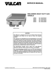
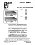
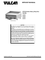
VCCG Series Heavy Duty Gas
Griddle
VCCG24
VCCG36
VCCG48
VCCG60
VCCG72
VCCG36 Shown
- NOTICE This Manual is prepared for the use of trained Vulcan Service
Technicians and should not be used by those not properly
qualified.
This manual is not intended to be all encompassing. If you have
not attended a Vulcan Service School for this product, you should
read, in its entirety, the repair procedure you wish to perform to
determine if you have the necessary tools, instruments and skills
required to perform the procedure. Procedures for which you do
not have the necessary tools, instruments and skills should be
performed by a trained Vulcan Service Technician.
The reproduction, transfer, sale or other use of this Manual,
without the express written consent of Vulcan, is prohibited.
This manual has been provided to you by ITW Food Equipment
Group LLC ("ITW FEG") without charge and remains the property
of ITW FEG, and by accepting this manual you agree that you will
return it to ITW FEG promptly upon its request for such return at
any time in the future.
A product of Vulcan-Hart
3600 North Point Blvd Baltimore, MD 21222
F45533 (1014)
VCCG Series Heavy Duty Gas Griddle
TABLE OF CONTENTS
GENERAL . . . . . . . . . . . . . . . . . . . . . . . . . . . . . . . . . . . . . . . . . . . . . . . . . . . . . . . . . . . . . . . . . . . . . . . . . . . . . . . . . . . . . . . . . . . . . . . . . .
INTRODUCTION . . . . . . . . . . . . . . . . . . . . . . . . . . . . . . . . . . . . . . . . . . . . . . . . . . . . . . . . . . . . . . . . . . . . . . . . . . . . . . . . . . . . . . .
MODELS . . . . . . . . . . . . . . . . . . . . . . . . . . . . . . . . . . . . . . . . . . . . . . . . . . . . . . . . . . . . . . . . . . . . . . . . . . . . . . . . . . . . . . . . . . . . . . .
INSTALLATION . . . . . . . . . . . . . . . . . . . . . . . . . . . . . . . . . . . . . . . . . . . . . . . . . . . . . . . . . . . . . . . . . . . . . . . . . . . . . . . . . . . . . . . .
OPERATION . . . . . . . . . . . . . . . . . . . . . . . . . . . . . . . . . . . . . . . . . . . . . . . . . . . . . . . . . . . . . . . . . . . . . . . . . . . . . . . . . . . . . . . . . . .
SPECIFICATIONS . . . . . . . . . . . . . . . . . . . . . . . . . . . . . . . . . . . . . . . . . . . . . . . . . . . . . . . . . . . . . . . . . . . . . . . . . . . . . . . . . . . . . .
TOOLS . . . . . . . . . . . . . . . . . . . . . . . . . . . . . . . . . . . . . . . . . . . . . . . . . . . . . . . . . . . . . . . . . . . . . . . . . . . . . . . . . . . . . . . . . . . . . . . . .
3
3
3
3
3
3
3
REMOVAL AND REPLACEMENT OF PARTS . . . . . . . . . . . . . . . . . . . . . . . . . . . . . . . . . . . . . . . . . . . . . . . . . . . . . . . . . . . . . . . 5
FRONT PANEL . . . . . . . . . . . . . . . . . . . . . . . . . . . . . . . . . . . . . . . . . . . . . . . . . . . . . . . . . . . . . . . . . . . . . . . . . . . . . . . . . . . . . . . . . 5
BACK PANEL . . . . . . . . . . . . . . . . . . . . . . . . . . . . . . . . . . . . . . . . . . . . . . . . . . . . . . . . . . . . . . . . . . . . . . . . . . . . . . . . . . . . . . . . . . 5
CONTROL DEFLECTOR (HEAT SHIELD) . . . . . . . . . . . . . . . . . . . . . . . . . . . . . . . . . . . . . . . . . . . . . . . . . . . . . . . . . . . . . . . 5
TEMPERATURE CONTROLLER . . . . . . . . . . . . . . . . . . . . . . . . . . . . . . . . . . . . . . . . . . . . . . . . . . . . . . . . . . . . . . . . . . . . . . . . 6
RADIANT BURNER . . . . . . . . . . . . . . . . . . . . . . . . . . . . . . . . . . . . . . . . . . . . . . . . . . . . . . . . . . . . . . . . . . . . . . . . . . . . . . . . . . . . 6
THERMOCOUPLE (RADIANT BURNER) . . . . . . . . . . . . . . . . . . . . . . . . . . . . . . . . . . . . . . . . . . . . . . . . . . . . . . . . . . . . . . . . 7
REMOVAL . . . . . . . . . . . . . . . . . . . . . . . . . . . . . . . . . . . . . . . . . . . . . . . . . . . . . . . . . . . . . . . . . . . . . . . . . . . . . . . . . . . . . . . . . 7
INSTALLATION . . . . . . . . . . . . . . . . . . . . . . . . . . . . . . . . . . . . . . . . . . . . . . . . . . . . . . . . . . . . . . . . . . . . . . . . . . . . . . . . . . . . 8
PILOT (RADIANT BURNER) . . . . . . . . . . . . . . . . . . . . . . . . . . . . . . . . . . . . . . . . . . . . . . . . . . . . . . . . . . . . . . . . . . . . . . . . . . . . 8
IGNITION MODULE . . . . . . . . . . . . . . . . . . . . . . . . . . . . . . . . . . . . . . . . . . . . . . . . . . . . . . . . . . . . . . . . . . . . . . . . . . . . . . . . . . . . 9
GAS VALVE . . . . . . . . . . . . . . . . . . . . . . . . . . . . . . . . . . . . . . . . . . . . . . . . . . . . . . . . . . . . . . . . . . . . . . . . . . . . . . . . . . . . . . . . . . . . 9
INFRARED BURNER . . . . . . . . . . . . . . . . . . . . . . . . . . . . . . . . . . . . . . . . . . . . . . . . . . . . . . . . . . . . . . . . . . . . . . . . . . . . . . . . . . 10
THERMOCOUPLE (INFRARED BURNER) . . . . . . . . . . . . . . . . . . . . . . . . . . . . . . . . . . . . . . . . . . . . . . . . . . . . . . . . . . . . . 11
REMOVAL . . . . . . . . . . . . . . . . . . . . . . . . . . . . . . . . . . . . . . . . . . . . . . . . . . . . . . . . . . . . . . . . . . . . . . . . . . . . . . . . . . . . . . . . 11
INSTALLATION . . . . . . . . . . . . . . . . . . . . . . . . . . . . . . . . . . . . . . . . . . . . . . . . . . . . . . . . . . . . . . . . . . . . . . . . . . . . . . . . . . . 11
IGNITOR (INFRARED BURNER) . . . . . . . . . . . . . . . . . . . . . . . . . . . . . . . . . . . . . . . . . . . . . . . . . . . . . . . . . . . . . . . . . . . . . . 12
PILOT ORIFICE (INFRARED BURNER) . . . . . . . . . . . . . . . . . . . . . . . . . . . . . . . . . . . . . . . . . . . . . . . . . . . . . . . . . . . . . . . 12
GRIDDLE PLATE ASSEMBLY . . . . . . . . . . . . . . . . . . . . . . . . . . . . . . . . . . . . . . . . . . . . . . . . . . . . . . . . . . . . . . . . . . . . . . . . . 13
SERVICE PROCEDURES AND ADJUSTMENTS . . . . . . . . . . . . . . . . . . . . . . . . . . . . . . . . . . . . . . . . . . . . . . . . . . . . . . . . . . .
TEMPERATURE CONTROLLER CALIBRATION . . . . . . . . . . . . . . . . . . . . . . . . . . . . . . . . . . . . . . . . . . . . . . . . . . . . . . .
RADIANT BURNER - AIR SHUTTER ADJUSTMENT . . . . . . . . . . . . . . . . . . . . . . . . . . . . . . . . . . . . . . . . . . . . . . . . . . .
GAS MANIFOLD PRESSURE ADJUSTMENT . . . . . . . . . . . . . . . . . . . . . . . . . . . . . . . . . . . . . . . . . . . . . . . . . . . . . . . . . .
BURNER GAS ORIFICE CHECK . . . . . . . . . . . . . . . . . . . . . . . . . . . . . . . . . . . . . . . . . . . . . . . . . . . . . . . . . . . . . . . . . . . . . .
THERMOCOUPLE TEST . . . . . . . . . . . . . . . . . . . . . . . . . . . . . . . . . . . . . . . . . . . . . . . . . . . . . . . . . . . . . . . . . . . . . . . . . . . . . .
TEMPERATURE CONTROLLER TEST . . . . . . . . . . . . . . . . . . . . . . . . . . . . . . . . . . . . . . . . . . . . . . . . . . . . . . . . . . . . . . . .
IGNITION MODULE TEST . . . . . . . . . . . . . . . . . . . . . . . . . . . . . . . . . . . . . . . . . . . . . . . . . . . . . . . . . . . . . . . . . . . . . . . . . . . . .
RADIANT BURNER - PILOT FLAME ADJUSTMENT . . . . . . . . . . . . . . . . . . . . . . . . . . . . . . . . . . . . . . . . . . . . . . . . . . .
GAS VALVE TESTS . . . . . . . . . . . . . . . . . . . . . . . . . . . . . . . . . . . . . . . . . . . . . . . . . . . . . . . . . . . . . . . . . . . . . . . . . . . . . . . . . . .
INFRARED BURNER . . . . . . . . . . . . . . . . . . . . . . . . . . . . . . . . . . . . . . . . . . . . . . . . . . . . . . . . . . . . . . . . . . . . . . . . . . . . . . . . . .
ADJUSTMENT . . . . . . . . . . . . . . . . . . . . . . . . . . . . . . . . . . . . . . . . . . . . . . . . . . . . . . . . . . . . . . . . . . . . . . . . . . . . . . . . . . . .
FLAME APPEARANCE . . . . . . . . . . . . . . . . . . . . . . . . . . . . . . . . . . . . . . . . . . . . . . . . . . . . . . . . . . . . . . . . . . . . . . . . . . . .
14
14
15
15
16
17
17
18
19
19
20
20
20
ELECTRICAL OPERATION . . . . . . . . . . . . . . . . . . . . . . . . . . . . . . . . . . . . . . . . . . . . . . . . . . . . . . . . . . . . . . . . . . . . . . . . . . . . . . . .
COMPONENT FUNCTION . . . . . . . . . . . . . . . . . . . . . . . . . . . . . . . . . . . . . . . . . . . . . . . . . . . . . . . . . . . . . . . . . . . . . . . . . . . .
SEQUENCE OF OPERATION . . . . . . . . . . . . . . . . . . . . . . . . . . . . . . . . . . . . . . . . . . . . . . . . . . . . . . . . . . . . . . . . . . . . . . . . .
GRIDDLE WIRING DIAGRAM . . . . . . . . . . . . . . . . . . . . . . . . . . . . . . . . . . . . . . . . . . . . . . . . . . . . . . . . . . . . . . . . . . . . . . . . .
21
21
21
22
TROUBLESHOOTING . . . . . . . . . . . . . . . . . . . . . . . . . . . . . . . . . . . . . . . . . . . . . . . . . . . . . . . . . . . . . . . . . . . . . . . . . . . . . . . . . . . . .
TEMPERATURE CONTROLLER - LED DIAGNOSTICS AND OPERATING STATUS . . . . . . . . . . . . . . . . . . . .
IGNITION MODULE - LED DIAGNOSTICS AND OPERATING STATUS . . . . . . . . . . . . . . . . . . . . . . . . . . . . . . . .
GENERAL . . . . . . . . . . . . . . . . . . . . . . . . . . . . . . . . . . . . . . . . . . . . . . . . . . . . . . . . . . . . . . . . . . . . . . . . . . . . . . . . . . . . . . . . . . . .
INFRARED BURNER . . . . . . . . . . . . . . . . . . . . . . . . . . . . . . . . . . . . . . . . . . . . . . . . . . . . . . . . . . . . . . . . . . . . . . . . . . . . . . . . . .
RADIANT BURNER . . . . . . . . . . . . . . . . . . . . . . . . . . . . . . . . . . . . . . . . . . . . . . . . . . . . . . . . . . . . . . . . . . . . . . . . . . . . . . . . . . .
23
23
23
24
26
26
© VULCAN 2014
F45533 (1014)
Page 2 of 26
VCCG Series Heavy Duty Gas Griddle - GENERAL
GENERAL
INTRODUCTION
OPERATION
This Service Manual covers specific service
information related to the models listed on the front
cover. Procedures in this manual will apply to all
VCCG Heavy Duty Gas Griddles unless otherwise
specified. Raising the griddle plate is not required for
servicing the griddle components. Griddle
components are serviced through the front and rear.
Pictures and illustrations can be of any model unless
the picture or illustration needs to be model specific.
The VCCG griddles are available with three different
cooking surface types:
Detailed operation instructions are included in the
Installation & Operation Manual sent with each unit.
The manual is also available online at
www.vulcanequipment.com.
SPECIFICATIONS
Electrical
- 120VAC 50/60Hz 2 amp single phase.
- 6 foot corded plug with ground provided.
•
Steel (standard).
Gas Manifold Pressure:
•
Chrome (optional).
- Natural Gas 4.0" W.C.
•
Rapid Recovery™ Griddle Plate* (optional).
- Propane Gas 10.0" W.C.
*The Rapid Recovery Griddle plate is a composite
material which is engineered to provide a high heat
transfer rate to the food. The top surface can be
scored or dented by careless use of a spatula or
scraper. The center of the plate is an aluminum core
with sheets of stainless steel laminated to the top and
bottom exterior surfaces.
Incoming Gas Pressure:
MODELS
- 7" to 9" W.C. Natural Gas
- 11" to 12" W.C. Propane Gas.
- Incoming pressure should not exceed 14.0" W.C.
(0.5 PSI) for either gas type.
Burner Types
- Griddles with Infrared Burners have one 24,000 BTU/
HR burner for each 12" of griddle width.
Vulcan
•
VCCG24 - 24" x 24" (width x depth) griddle plate.
•
VCCG36 - 36" x 24" (width x depth) griddle plate.
•
VCCG48 - 48" x 24" (width x depth) griddle plate.
•
VCCG60 - 60" x 24" (width x depth) griddle plate.
•
VCCG72 - 72" x 24" (width x depth) griddle plate.
INSTALLATION
Generally, installations are made by the dealer or
contracted by the dealer or owner. Detailed
installation instructions are included in Installation &
Operation Manual that is sent with each unit.
It should be noted that an improperly installed unit,
especially an unleveled unit can lead to premature
electrical component failures. A unit that is higher in
the front will cause the flue gases to vent improperly
and gather in the front near the electrical components.
- Griddles with Radiant Burners* have one 30,000
BTU/HR burner for each 12" of griddle width.
*Atmospheric type “U” shaped aluminized steel.
Controls
- One Solid State thermostat with thermocouple probe
for each 12" of griddle width.
- Temperature adjustment range 150°F to 550°F on all
griddle plate surface types except the Rapid Recovery
Griddle plate (150°F to 450°F).
- One Electronic Ignition module with pilot safety
system for each 12" of griddle width.
- One Dual Solenoid gas valve with internal regulator
for each 12" of griddle width.
TOOLS
Standard
•
Standard set of hand tools.
•
VOM with ability to measure micro amp current.
Page 3 of 26
F45533 (1014)
VCCG Series Heavy Duty Gas Griddle - GENERAL
•
VOM with minimum of NFPA-70E CAT III 600V,
UL/CSA/TUV listed. Sensitivity of at least 20,000
ohms per volt. Meter leads must also be rated at
CAT III 600V.
•
Temperature tester (K type thermocouple
preferred) with surface probe.
•
U-Tube or Digital Manometer.
•
Thread sealant suitable for use with natural or
propane gas.
Special
•
Torque wrench capable of measuring at least 25
in-lbs. for tightening thermocouple probe to
griddle plate. Bolt size 5/16"-18.
•
Safekote 60™ or equivalent Heat Transfer and
Anti-Seize Compound rated for 600°F (purchase
locally). Apply to thermocouple probe.
F45533 (1014)
Page 4 of 26
VCCG Series Heavy Duty Gas Griddle - REMOVAL AND REPLACEMENT OF PARTS
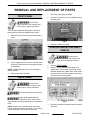
REMOVAL AND REPLACEMENT OF PARTS
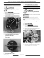
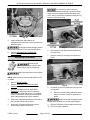
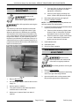
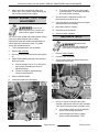
FRONT PANEL
1.
Disconnect gas supply at griddle.
2.
Remove all screws from rear of griddle securing
the back panel.
Disconnect the
electrical power to the machine and
follow lockout / tagout procedures.
The front panel holds the temperature controllers,
thermostat cycle lights and lighted power switch.
1.
Remove four screws securing the front panel to
frame.
Fig. 2
3.
Reverse procedure to install.
CONTROL DEFLECTOR (HEAT
SHIELD)
Disconnect the
electrical power to the machine and
follow lockout / tagout procedures.
Fig. 1
2.
Lay front panel face down in front of the unit while
servicing. Pull the drawer out to support the panel
as necessary.
NOTE: Griddles that are 60" and 72" wide have 2
grease drawers.
3.
1.
Remove FRONT PANEL.
2.
Remove control deflector (heat shield) from
griddle frame. The number of mounting screws
installed depends on griddle width. After screws
are removed, lift the control deflector and rotate
forward to remove from griddle.
Reverse procedure to install.
BACK PANEL
Disconnect the
electrical power to the machine and
follow lockout / tagout procedures.
Shut off the gas before servicing the
unit.
All gas joints disturbed during
servicing must be checked for leaks. Check with a
soap and water solution (bubbles). Do not use an open
flame.
Fig. 3
3.
Reverse procedure to install and check for proper
operation.
Page 5 of 26
F45533 (1014)
NOTE: Remove the back panel when servicing a
burner, temperature probe, pilot burner; or to remove
excessive grease build up from the flue area.
VCCG Series Heavy Duty Gas Griddle - REMOVAL AND REPLACEMENT OF PARTS
7.
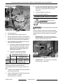
TEMPERATURE CONTROLLER
RADIANT BURNER
Disconnect the
electrical power to the machine and
follow lockout / tagout procedures.
1.
Remove FRONT PANEL.
2.
Note wire connections then disconnect them
from temperature controller.
3.
Loosen screws securing knob guard to front
panel to provide clearance for knob removal.
Check TEMPERATURE CONTROLLER
CALIBRATION.
Disconnect the
electrical power to the machine and
follow lockout / tagout procedures.
Shut off the gas before servicing the
unit.
All gas joints disturbed during
servicing must be checked for leaks. Check with a
soap and water solution (bubbles). Do not use an open
flame.
NOTE: Radiant burner is removed through the front
of griddle.
1.
Remove BACK PANEL.
2.
Remove FRONT PANEL.
3.
Remove CONTROL DEFLECTOR (HEAT
SHIELD).
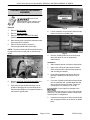
4.
Remove burner flexible tubing from the burner
orifice elbow and gas valve fitting.
Fig. 4
4.
Loosen set screw then remove knob from
temperature control shaft.
5.
Remove screws securing temperature controller
to front panel.
Fig. 6
5.
Fig. 5
6.
Reverse procedure to install.
F45533 (1014)
Page 6 of 26
Disconnect compression fitting from gas valve
inlet and slide gas valve off the tubing.
VCCG Series Heavy Duty Gas Griddle - REMOVAL AND REPLACEMENT OF PARTS
Fig. 9
9.
Fig. 7
6.
Note thermocouple connections then disconnect
from temperature controller.
7.
Remove burner shield assembly and burner from
griddle (burner remains attached to the burner
shield assembly).
Align mounting screw head on the burner air
shutter to the slot in heat shield assembly hole
and remove burner from heat shield.
10. Reverse procedure to install and check for proper
operation.
THERMOCOUPLE (RADIANT
BURNER)
Disconnect the
electrical power to the machine and
follow lockout / tagout procedures.
Removal
1.
Remove RADIANT BURNER (steps 1 through 8)
to access thermocouple shield and
thermocouple.
2.
Push thermocouple shield toward the front of
griddle to disengage the rear mounting tab on
thermocouple shield from the support bracket on
the bottom of griddle plate.
Fig. 8
NOTE: When installing burner, ensure the locating
pin and mounting plate at the rear of burner are
properly inserted in the mounting slot. At the front of
griddle, ensure the thermocouple shield front
mounting tab is inserted in the burner shield slot to
support the thermocouple shield.
8.
Remove orifice holder bracket from burner shield
assembly.
Fig. 10
3.
Loosen mounting nut and remove thermocouple
probe from bottom of griddle plate.
Page 7 of 26
F45533 (1014)
VCCG Series Heavy Duty Gas Griddle - REMOVAL AND REPLACEMENT OF PARTS
PILOT (RADIANT BURNER)
Disconnect the
electrical power to the machine and
follow lockout / tagout procedures.
Fig. 11
4.
Shut off the gas before servicing the
Remove insulating sleeve from thermocouple
wires and retain for use on replacement
thermocouple.
unit.
Installation
All gas joints disturbed during
servicing must be checked for leaks. Check with a
soap and water solution (bubbles). Do not use an open
flame.
1.
Slide insulating sleeve over thermocouple wires.
2.
Apply a thin coating of heat transfer and antiseize compound to the thermocouple probe tip
and mounting nut threads.
1.
Remove RADIANT BURNER.
2.
Disconnect compression fitting from pilot.
3.
Route thermocouple probe through the front
opening in griddle frame and lay it on top of
burner mounting panel.
When disconnecting compression fitting
for the pilot, support bracket to prevent bending.
4.
From rear of griddle, thread thermocouple probe
into the mounting hole in griddle plate and stop
when probe tip touches the plate. Torque the
mounting nut to a maximum of 25 in-lbs.
Do not over tighten or damage to the
thermocouple probe may occur. Due to the aluminum
plate core, it is also possible to create a raised area
over the probe if overtightened.
5.
Insert rear mounting tab on thermocouple shield
into the support bracket on the bottom of griddle
plate.
6.
Route thermocouple wires through the opening
in burner shield assembly.
7.
Re-install RADIANT BURNER.
8.
Check TEMPERATURE CONTROLLER
CALIBRATION.
3.
Remove pilot and mounting bracket from the
burner mounting panel.
4.
Pull spark wire through the hole in control
mounting panel and remove pilot from griddle.
5.
Remove pilot from pilot mounting bracket.
Fig. 12
6.
Reverse procedure to install.
NOTE: When installing, verify spark gap is 1/8".
F45533 (1014)
Page 8 of 26
VCCG Series Heavy Duty Gas Griddle - REMOVAL AND REPLACEMENT OF PARTS
GAS VALVE
Disconnect the
electrical power to the machine and
follow lockout / tagout procedures.
Shut off the gas before servicing the
unit.
All gas joints disturbed during
servicing must be checked for leaks. Check with a
soap and water solution (bubbles). Do not use an open
flame.
NOTE: The gas valve is dual solenoid with internal
regulator. One valve supplies gas for the pilot burner
and the other valve supplies gas for the main burner.
Fig. 13
7.
Check for proper operation.
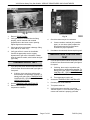
IGNITION MODULE
1.
Remove FRONT PANEL.
2.
Note lead wire locations and disconnect from gas
valve.
Disconnect the
electrical power to the machine and
follow lockout / tagout procedures.
1.
Remove FRONT PANEL.
2.
Disconnect ignitor cable and wire harness
connector.
3.
Remove two screws securing ignition module to
the mounting panel.
Fig. 15
3.
Disconnect compression fitting nuts (3 places)
and remove gas valve from griddle.
4.
Note position of the four compression fitting
elbows and one pipe bushing on gas valve.
Remove fittings from valve.
Fig. 14
4.
Reverse procedure to install and verify proper
operation.
Page 9 of 26
F45533 (1014)
VCCG Series Heavy Duty Gas Griddle - REMOVAL AND REPLACEMENT OF PARTS
Two wrenches may be required to
disconnect compression fittings if the orifice fittings
begin to turn or damage to the flexible tubing may
occur. Use (1) wrench on compression fitting and (1)
wrench on the orifice fitting.
Fig. 16
5.
Install compression fitting elbows on
replacement gas valve then reverse procedure to
install the valve.
Clean pipe threads and apply thread
sealant that is suitable for use with propane gases.
6.
Perform GAS MANIFOLD PRESSURE
ADJUSTMENT.
Fig. 17
6.
Disconnect the pilot and burner flexible tubing
from gas valve.
7.
Remove screws (2) securing front of burner to
frame.
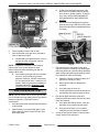
INFRARED BURNER
Disconnect the
electrical power to the machine and
follow lockout / tagout procedures.
Shut off the gas before servicing the
unit.
NOTE: Infrared burner is removed through the front
of griddle.
1.
Remove FRONT PANEL.
2.
Remove CONTROL DEFLECTOR (HEAT
SHIELD).
3.
Perform THERMOCOUPLE (INFRARED
BURNER) removal procedure to access the
thermocouple shield and remove it. The shield
must be removed for burner removal clearance
but the thermocouple can remain installed.
Fig. 18
8.
Lift burner up at the front and pull out to remove
from griddle.
A.
Remove pilot orifice fitting and burner orifice
fitting from burner. Install on replacement
burner.
4.
Disconnect compression fitting from pilot orifice
fitting at pilot venturi inlet on burner.
Clean pipe threads and apply thread
sealant that is suitable for use with propane gases.
5.
Disconnect compression fitting from burner
orifice fitting at burner venturi inlet.
9.
F45533 (1014)
Reverse procedure to install replacement burner.
10. Check for proper operation.
Page 10 of 26
VCCG Series Heavy Duty Gas Griddle - REMOVAL AND REPLACEMENT OF PARTS
THERMOCOUPLE (INFRARED
BURNER)
Disconnect the
electrical power to the machine and
follow lockout / tagout procedures.
Removal
Fig. 20
1.
Remove BACK PANEL.
2.
Remove FRONT PANEL.
3.
Remove CONTROL DEFLECTOR (HEAT
SHIELD).
4.
Note thermocouple connections then disconnect
from temperature controller.
5.
Remove burner shield to access the
thermocouple shield and thermocouple.
8.
Loosen mounting nut and remove thermocouple
probe from bottom of griddle plate.
NOTE: The burner shield provides a slotted opening
to support the front mounting tab on thermocouple
shield.
Fig. 21
9.
Remove insulating sleeve from thermocouple
wires and retain for use on replacement
thermocouple.
Installation
1.
Slide insulating sleeve over thermocouple wires.
2.
Apply a thin coating of heat transfer and antiseize compound to the thermocouple probe tip
and mounting nut threads.
3.
Route thermocouple probe through the front
opening in griddle frame and lay it on top of
burner.
4.
From rear of griddle, thread thermocouple probe
into the mounting hole in griddle plate and stop
when probe tip touches the plate. Torque the
mounting nut to a maximum of 25 in-lbs.
Fig. 19
6.
Remove IGNITOR (INFRARED BURNER) from
burner shield.
7.
Push thermocouple shield toward the front of
griddle to disengage the rear mounting tab on
thermocouple shield from the support bracket on
the bottom of griddle plate.
Do not over tighten or damage to the
thermocouple probe may occur. Due to the aluminum
plate core, it is also possible to create a raised area
over the probe if overtightened.
5.
Page 11 of 26
Insert rear mounting tab on thermocouple shield
into the support bracket on the bottom of griddle
plate.
F45533 (1014)
VCCG Series Heavy Duty Gas Griddle - REMOVAL AND REPLACEMENT OF PARTS
6.
Route thermocouple wires through the opening
in burner shield. Lift burner shield and position it
so the front mounting tab on the thermocouple
shield can be inserted into the upper slotted
opening in the burner shield. Secure burner
shield to griddle.
7.
Install ignitor to burner shield.
8.
Connect thermocouple wires to the temperature
controller.
9.
Install control deflector (heat shield).
10. Install front and back panels.
11. Check TEMPERATURE CONTROLLER
CALIBRATION.
Fig. 23
PILOT ORIFICE (INFRARED
BURNER)
IGNITOR (INFRARED BURNER)
Disconnect the
electrical power to the machine and
follow lockout / tagout procedures.
Disconnect the
electrical power to the machine and
follow lockout / tagout procedures.
1.
Remove FRONT PANEL.
2.
Note connection locations then disconnect ignitor
cable and jumper from ignitor terminals.
3.
Remove screws securing ignitor to burner shield.
Shut off the gas before servicing the
unit.
All gas joints disturbed during
servicing must be checked for leaks. Check with a
soap and water solution (bubbles). Do not use an open
flame.
1.
Remove FRONT PANEL.
2.
Remove CONTROL DEFLECTOR (HEAT
SHIELD).
3.
Remove burner shield.
Fig. 22
4.
Ensure spark gap between ignitor electrode and
ground rod is approximately 1/8". If adjustment is
necessary, position the ground rod to achieve the
correct spark gap.
5.
Reverse procedure to install and check for proper
operation.
F45533 (1014)
Fig. 24
4.
Page 12 of 26
Disconnect compression fitting from pilot orifice
fitting.
VCCG Series Heavy Duty Gas Griddle - REMOVAL AND REPLACEMENT OF PARTS
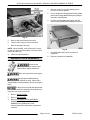
4.
Remove screws (2) securing griddle plate to
frame at the front of griddle.
5.
Cut two lengths of 2x4 appropriate for the griddle
plate width, leaving additional length to grasp on
each side of griddle plate.
6.
Lift front of griddle plate and support with 2x4
then lift rear of griddle plate and support with 2x4.
Fig. 25
5.
Remove pilot orifice fitting from burner.
6.
Tilt pilot orifice fitting to remove the orifice.
7.
Reverse procedure to install.
NOTE: When installing, verify orifice size is correct
for gas type and is free from debris. Clean the orifice
with air or water only.
8.
Fig. 26
7.
Lift griddle plate and remove from base of
equipment.
8.
Reverse procedure for installation.
Check for proper operation.
GRIDDLE PLATE ASSEMBLY
Disconnect the
electrical power to the machine and
follow lockout / tagout procedures.
Shut off the gas before servicing the
unit.
All gas joints disturbed during
servicing must be checked for leaks. Check with a
soap and water solution (bubbles). Do not use an open
flame.
For larger units, removal and replacement
of the griddle plate weld assembly should be done by
more than one service technician .
1.
Remove FRONT PANEL.
2.
Remove BACK PANEL.
3.
Remove THERMOCOUPLE (INFRARED
BURNER) or THERMOCOUPLE (RADIANT
BURNER) from griddle plate. Leave
thermocouple wires connected at temperature
controller.
Page 13 of 26
F45533 (1014)
VCCG Series Heavy Duty Gas Griddle - SERVICE PROCEDURES AND ADJUSTMENTS
SERVICE PROCEDURES AND ADJUSTMENTS
•
TEMPERATURE CONTROLLER
CALIBRATION
NOTE: Ensure the griddle is level before performing
calibration as outlined under LEVELING in the
Installation & Operation Manual.
NOTE: Do not use an infrared thermometer for
measuring griddle surface temperatures. These
devices are highly sensitive to surface color (clean or
dirty), angle of reading and distance from the surface.
Use a temperature meter with surface probe for all
griddle surface temperature measurements.
If temperature measurement is outside of
tolerance then temperature control must be
calibrated.
CALIBRATING TEMPERATURE CONTROL
1.
Remove FRONT PANEL.
2.
Loosen screws (2) securring knob guard to the
control panel for temperature controller being
calibrated.
3.
Loosen set screw then remove knob from
temperature control shaft. Do not rotate the knob
during removal.
Fig. 28
Fig. 27
4.
Loosen screws on the temperature dial so the
dial will rotate.
5.
Install knob onto the temperature control shaft.
Do not rotate the knob during installation.
6.
Rotate temperature dial to match the
temperature reading. Hold dial in position and
remove knob. This adjustment offsets the
indicated temperature on the dial to the actual
temperature measured.
7.
Tighten dial screws.
8.
Install knob onto the temperature control shaft
and tighten set screw.
9.
Repeat CALIBRATION CHECK to verify
adjustment. Adjust calibration until temperature
is within tolerance.
CALIBRATION CHECK
1.
2.
Each temperature controller controls a 12" zone
of the griddle. Center point area of cooking zones
are located 6" from the side splash (left or right),
every 12" across the width of griddle, and 12"
back from the front of griddle plate.
Clean the center point areas of cooking zones to
ensure good contact with surface probe.
3.
Set thermostats to 350°F and allow the
thermostat cycle light to cycle ON and OFF at
least three times to stabilize griddle surface
temperatures.
4.
Monitor the thermostat cycle light for the
temperature controller calibration being checked.
When the light cycles OFF, record temperature
for that zone.
•
If temperature measurement is 350°F ±10°F
the control is properly calibrated.
F45533 (1014)
Page 14 of 26
VCCG Series Heavy Duty Gas Griddle - SERVICE PROCEDURES AND ADJUSTMENTS
RADIANT BURNER - AIR SHUTTER
ADJUSTMENT
Disconnect the
electrical power to the machine and
follow lockout / tagout procedures.
Shut off the gas before servicing the
unit.
If a proper flame is observed as described
in the beginning paragraph, no further
adjustment is necessary.
B.
If flame is yellow tipping and lifting from
burner, continue with procedure to adjust.
6.
Disconnect power and turn gas supply off.
7.
Remove RADIANT BURNER.
NOTE: The factory default air shutter positions are
half open natural; full open propane.
8.
The efficiency of the burner depends on a delicate
balance between the air supply and volume of gas.
Whenever this balance is disturbed, poor operating
characteristics and excessive gas consumption may
occur. An air shutter on the front of the burner controls
the gas mixer balance. A yellow streaming flame on
the burner is an indication of insufficient primary air. A
white-blue flame is a result of excessive primary air. A
proper flame should be blue in color, well-defined and
seated on the burner port.
A.
9.
Loosen the air shutter screw and hold the shutter
in place to prevent movement.
A.
If flame is yellow streaming, slightly rotate
shutter to open it. Hold shutter in position
and tighten screw to secure the shutter.
B.
If flame is white-blue, slightly rotate shutter
to close it. Hold shutter in position and
tighten screw to secure the shutter.
Install radiant burner.
10. Install back panel.
11. Check for proper operation.
GAS MANIFOLD PRESSURE
ADJUSTMENT
Disconnect the
electrical power to the machine and
follow lockout / tagout procedures.
Shut off the gas before servicing the
unit.
Fig. 29
1.
Remove BACK PANEL.
2.
Re-connect gas supply to machine then turn the
supply on.
3.
Connect power to machine.
4.
Turn power switch on and rotate temperature
controller knob to call for heat.
5.
With burner lit, observe flame from back of
machine.
1.
Remove FRONT PANEL.
2.
Connect manometer to the pressure check fitting
at the top of gas valve being checked.
3.
Open the needle valve on the pressure check
fitting to allow gas pressure measurement.
Page 15 of 26
F45533 (1014)
VCCG Series Heavy Duty Gas Griddle - SERVICE PROCEDURES AND ADJUSTMENTS
10. Once the correct pressure has been set, turn off
the power switch and gas supply. Return needle
valve to the closed position then disconnect
manometer.
11. Install the adjustment screw cap.
12. Check for proper operation.
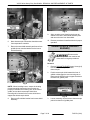
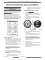
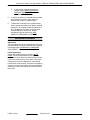
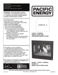
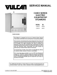
BURNER GAS ORIFICE CHECK
Disconnect the
electrical power to the machine and
follow lockout / tagout procedures.
Shut off the gas before servicing the
unit.
If burner operation seems poor and other systems
have been checked, access the burner for the griddle
section being serviced and inspect the burner gas
orifice.
Fig. 30
4.
Turn gas supply on.
5.
Connect power and turn power switch on.
6.
Set all the temperature controls on the griddle to
their highest setting and allow burners to light. All
burners must be lit during test and adjustment.
7.
Check manifold pressure reading and compare
to the value in the table below.
A.
If pressure is within the allowable tolerance,
then no adjustment is necessary. Turn off
the power switch and gas supply. Return
needle valve to the closed position then
disconnect manometer.
B.
If pressure is outside the allowable
tolerance, continue with procedure.
•
Radiant Burner - The gas orifice and elbow
fitting is mounted to the orifice holder bracket at
the front of the burner venturi inlet.
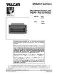
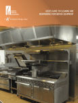
PRESSURE READINGS (IN W.C.)
GAS
TYPE
INCOMING LINE
MANIFOLD RECOMMEND
Natural
4.0
7.0 to 9.0
Propane
10.0
11.0 to 12.0
Fig. 31
MAX
•
14.0
NOTE: To correctly set the manifold pressure, the
incoming line pressure must be within the
recommended values for the gas type shown in the
table.
8.
To adjust, remove adjustment screw cap from the
gas valve being checked.
9.
Turn the adjusting screw to obtain the proper gas
pressure (clockwise = increase;
counterclockwise = decrease).
F45533 (1014)
Page 16 of 26
Infrared Burner - The gas orifice is mounted to
the burner at the venturi inlet.
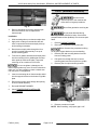
VCCG Series Heavy Duty Gas Griddle - SERVICE PROCEDURES AND ADJUSTMENTS
Fig. 32
1.
Remove FRONT PANEL.
2.
Verify gas orifice is threaded into the fitting
properly, and is centered and mounted
perpendicular to the burner venturi opening.
Adjust alignment as necessary.
Fig. 33
4.
A.
3.
Check gas orifice for blockage or damage. If dirty,
clean with air or water only.
4.
Verify gas orifice is correct for the altitude.
Contact the appropriate service support
department for gas orifice information. Please
have the machine model, serial number and gas
type ready.
5.
Cycle the power switch and set temperature knob
to call for heat. Observe thermostat cycle light on
front panel.
A.
If blinking, there may be a problem with
thermocouple or temperature controller. To
identify error code, refer to TEMPERATURE
CONTROLLER - LED DIAGNOSTICS AND
OPERATING STATUS .
If meter reads an overload (OL) condition
(open), or zero ohms (short) replace the
thermocouple and check temperature
controller for proper operation.
If resistance is measured, thermocouple is good.
TEMPERATURE CONTROLLER
TEST
1.
THERMOCOUPLE TEST
1.
Check the thermocouple for resistance.
Cycle the power switch and set temperature knob
to call for heat. Observe thermostat cycle light on
front panel.
A.
If blinking, there may be a problem with
thermocouple or temperature controller. To
identify error code, refer to TEMPERATURE
CONTROLLER - LED DIAGNOSTICS AND
OPERATING STATUS .
B.
Turn temperature knob to off.
2.
Access the TEMPERATURE CONTROLLER.
2.
Access TEMPERATURE CONTROLLER.
3.
Connect power to the machine.
3.
Remove thermocouple connections from
temperature controller.
4.
Turn power switch on.
5.
Verify temperature controller is receiving
120VAC at pins 1 & 2 on connector, polarity is
correct and machine is properly grounded.
Page 17 of 26
F45533 (1014)
VCCG Series Heavy Duty Gas Griddle - SERVICE PROCEDURES AND ADJUSTMENTS
A.
If LED is Red and blinking an error code,
there may be a problem with pilot burner,
flame sense or ignition module. To identify
error code, refer to IGNITION MODULE LED DIAGNOSTICS AND OPERATING
STATUS .
B.
LED is Green and blinking during ignition
trial and inter-purge. LED then turns to solid
Green when pilot flame is established (flame
is sensed).
Fig. 34
6.
Turn temperature knob to call for heat.
7.
Verify thermostat cycle light on the front panel
turns on and burner lights.
A.
If thermostat cycle light and burner come on
but turn off within 10 seconds, perform
THERMOCOUPLE TEST.
NOTE: Temperature controller will de-energize
internal relay if the circuitry detects an open
thermocouple and the thermostat cycle light will
display a blink code.
B.
Fig. 35
3.
If thermostat cycle light and burner do not
come on, verify internal relay contact
operation. Check for 120VAC at terminals 1
& 2 on gas solenoid valve. If voltage is not
present, install a replacement temperature
controller and perform TEMPERATURE
CONTROLLER CALIBRATION.
IGNITION MODULE TEST
NOTE: Igntion module has 10 second ignition trial
time, 5 second inter-purge (delay) before retry and will
attempt to light pilot 7 times then lockout if
unsuccessful.
1.
Cycle the power switch and set temperature knob
to call for heat.
2.
Ignition module is energized and ignition cycle
starts. Observe ignition module LED thru front
panel sight glass.
F45533 (1014)
4.
5.
Page 18 of 26
Pilot solenoid valve energized by pilot valve
output from ignition module (pin 2) allowing gas
flow to the pilot burner. Ignition module generates
spark voltage and ignitor begins sparking. If there
is no spark then check the following.
A.
Check for 120VAC at ignition module pin 3
(NEUTRAL) and pin 4 (120V).
B.
Inspect ignitor cable for damage and
continuity.
C.
Verify spark gap is set at 1/8".
D.
If component passes the above tests and is
not sparking, then replace ignition module.
Pilot burner lights and flame is sensed. If
electrode continues to spark after pilot is lit then
check the following.
A.
On models with Radiant burner, verify the
electrode is fully engulfed by pilot flame.
B.
Verify ground wire (pin 1) from ignition
module is securely grounded to chassis.
As long as the ignition module is sensing flame
current, then the pilot will stay lit.
VCCG Series Heavy Duty Gas Griddle - SERVICE PROCEDURES AND ADJUSTMENTS
6.
Main burner valve energized by main valve
output (pin 5) from ignition module allowing gas
flow to burner and the burner lights.
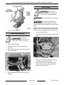
RADIANT BURNER - PILOT FLAME
ADJUSTMENT
Disconnect the
electrical power to the machine and
follow lockout / tagout procedures.
A.
To increase pilot flame turn valve needle
counterclockwise. To decrease pilot flame,
turn valve needle clockwise.
7.
Once pilot flame is adjusted correctly, turn
thermostat knob to call for heat.
8.
Verify pilot burner remains lit when burner lights.
Adjust pilot flame as necessary.
9.
Disconnect power to machine.
10. Install front and rear panels.
11. Check for proper operation.
GAS VALVE TESTS
The VCCG series griddle with Radiant burner utilizes
a gas valve (dual solenoid) and 90° elbow
compression fitting with needle valve adjustment to
control gas flow to pilot burner. Each 12" griddle
section has individual controls.
Disconnect the
electrical power to the machine and
follow lockout / tagout procedures.
1.
Turn thermostat knob to the off position.
2.
Remove BACK PANEL.
3.
Connect power to machine and turn power switch
on.
1.
Remove FRONT PANEL.
2.
Connect power to machine.
Ignitor begins sparking and pilot valve opens to
allow gas to pilot.
3.
Turn on power switch and adjust temperature
controller to call for heat.
4.
A.
If flame envelops 3/8" to 1/2" of the ignitor/
flame sense electrode, pilot burner is
adjusted properly.
B.
If flame is outside of specified range,
continue with procedure.
5.
Remove FRONT PANEL.
6.
Locate the needle valve and adjust.
Fig. 37
4.
Check for 120VAC to the gas valve (dual
solenoid) - Main burner solenoid valve (terminals
1 & 2) and Pilot solenoid valve (terminals 3 & 4).
A.
If no voltage to either one of the solenoid
valves, check wiring connections.
B.
If pilot solenoid valve has no voltage,
perform IGNITION MODULE TEST.
Fig. 36
Page 19 of 26
F45533 (1014)
VCCG Series Heavy Duty Gas Griddle - SERVICE PROCEDURES AND ADJUSTMENTS
C.
If main burner solenoid valve has no
voltage, perform IGNITION MODULE
TEST and TEMPERATURE
CONTROLLER TEST.
5.
If 120VAC is present on solenoid valve terminals
after performing previous steps, either the
solenoid coil or valve is malfunctioning.
6.
To determine if solenoid coil is malfunctioning,
check resistance between main burner solenoid
(terminals 1 & 2) and pilot solenoid (terminals 3
& 4). Readings of 100 ohms or less on either
solenoid indicate a shorted coil. Install a
replacement gas valve and verify GAS
MANIFOLD PRESSURE ADJUSTMENT.
INFRARED BURNER
Adjustment
The only adjustment for the Infared burner is the gas
manifold pressure. Verify the pressure is set correctly
as outlined under GAS MANIFOLD PRESSURE
ADJUSTMENT.
Flame Appearance
Access the infrared burner by removing BACK
PANEL. When the Infared burner first lights you
should see a small rolling blue flame, which will clear
up after the burner warms. Once warm, a low profile
orange flame is the best description of the Infared
burner flame. In some cases, if the burner is operating
correctly, you may not be able to see the actual flame.
Instead you will see the glow of the ceramic bricks in
the burner.
F45533 (1014)
Page 20 of 26
VCCG Series Heavy Duty Gas Griddle - ELECTRICAL OPERATION
ELECTRICAL OPERATION
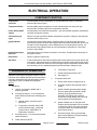
COMPONENT FUNCTION
Temperature
Controller . . . . . . . . . . . .
Controls griddle surface temperature for the individual heat zone by monitoring
thermocouple input (K type ).
Temperature Probe . . .
Senses griddle surface temperature for the individual heat zone using a K type
thermocouple. Provides input to the temperature controller.
Power Switch (SPST
switch) . . . . . . . . . . . . . . .
Controls power to all electrical components - gas valve (double regulated), temperature
controller and ignition module).
Thermostat Cycle
Light . . . . . . . . . . . . . . . . .
When lit, the light (red LED) indicates temperature controller is calling for heat (internal
contacts closed, output is on).
Ignition Module . . . . . .
Controls and monitors gas heating. Generates spark to light gas at the pilot burner,
monitors the presence of flame and energizes the main burner solenoid valve upon a call
for heat from the temperature control. Module has a 10 second ignition trial time, a 5
second inter-purge (delay) before retry and will attempt to light pilot for 7 times then
lockout if unsuccessful.
Ignitor/Flame Sense
Electrode . . . . . . . . . . . . .
Ignites pilot burner and senses the presence of a flame. Provides flame sense input to
the ignition module.
Pilot Burner . . . . . . . . . .
When lit, lights the main burner.
Gas Valve . . . . . . . . . . . .
A dual solenoid valve with internal regulator that controls gas flow to the pilot burner and
main burner. Pilot solenoid valve is energized by the ignition module after power switch
is turned on. Main burner solenoid valve is energized by the temperature controller after
the pilot safety circuit is established (pilot lit) and thermostat is calling for heat.
SEQUENCE OF OPERATION
E.
Temperature knobs OFF.
F.
Griddle temperature below 150°F.
Operation is the same for all griddle models. Each 12"
heat zone on the griddle plate has its own temperature
controller, thermostat cycle light and ignition system
components. Refer to Griddle Wiring Diagram
AI3724.
G.
Gas supply on.
1.
2.
Conditions.
A.
120VAC connected to griddle and is
properly grounded.
B.
Incoming neutral line - L2 is connected to
power switch terminal N (non switching) and
to each:
1)
Ignition module connector at pin 3
NEUTRAL.
2)
Temperature controller at the LINE
terminal (internal relay - COM) and
jumpered to pin 2 NEUTRAL on
temperature controller.
C.
Incoming hot line - L1 is connected to power
switch terminal L1.
D.
Power switch off (SPST).
Page 21 of 26
Turn power switch ON.
A.
Power switch internal red light turns on.
B.
All ignition modules are powered at pin 4
(120V).
C.
Ignition modules generate spark voltage
from the spark/sense terminals to begin
sparking at the ignitor/flame sense
electrode. LED's blink green during 5
second inter-purge (delay) and 10 second
trial for ignition (normal operation).
D.
Ignition modules turn on the pilot valve
output at pin 2 and provide 120V to terminal
3 on the pilot valves. Pilot valve solenoids
on the gas valves are energized and gas
flows to pilot burners.
E.
Pilot burners light, flame is sensed and
ignitors stop sparking. LED stops blinking
and remains solid green.
F45533 (1014)
VCCG Series Heavy Duty Gas Griddle - ELECTRICAL OPERATION
3.
F.
Ignition modules turn on the main valve
output at pin 5.
C.
G.
L1 present at terminal 2 on the main valve
solenoids output and jumpered to LINE IN
at pin 1 on temperature controllers.
Temperature controllers are powered.
4.
Main burner solenoids on gas valves are
energized and gas flows to each burner.
Burners light and begin heating griddle.
Griddle will continue to cycle with the
temperature controller until the temperature knob
is turned off; or the power switch is turned off.
Turn temperature knobs to 350°F.
A.
Thermostat cycle lights (red) turn on. The
lights will cycle on/off with the call for heat.
B.
Temperature controller's internal contacts
close (N.O.) and provide L2 (neutral) from
the OUT terminal to terminal 1 for main
burner solenoids on the gas valves.
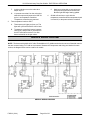
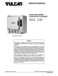
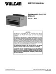
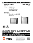
GRIDDLE WIRING DIAGRAM
NOTE: The base model griddle is 24" wide. Each additional 12" griddle section has its own set of identical controls
that are conected using a 12" add on wire harness. Because the components and wiring are identical for each
section, the diagram below can be used for all models.
GRIDDLE WIRING DIAGRAM
F45533 (1014)
Page 22 of 26
VCCG Series Heavy Duty Gas Griddle - TROUBLESHOOTING
TROUBLESHOOTING
TEMPERATURE CONTROLLER - LED DIAGNOSTICS AND OPERATING
STATUS
NOTE: Each of the individual thermostat LED's are externally mounted to the front panel and are refered to as
thermostat cycle lights. Each 12" griddle section has individual controls.
LED Codes
•
Solid Red - Indicates temperature controller internal relay is energized "Call For Heat" requested.
•
Two quick flashes every 3 seconds indicates a “No Heating” fault condition.
-
•
Three quick flashes every 3 seconds indicates temperature probe input circuit is open.
-
•
LED sequence is - ON for 1 second, OFF for 1 second, ON for 1 second, then OFF for 4 seconds and
repeats.
LED sequence is - ON for 1 second, OFF for 1 second, ON for 1 second, OFF for 1 second ON for 1
second, then OFF for 4 seconds and repeat.
Continuous ON - OFF - ON - OFF - ON cycle indicates an internal problem and the temperature controller
must be replaced.
IGNITION MODULE - LED DIAGNOSTICS AND OPERATING STATUS
LED Green for Normal Operation
•
Green, ½ sec on, ½ sec off
- Inter-purge (delay before ignition re-try if flame is lost)
•
Green, blinking rapidly
- Trial for ignition
•
Green, on solid
- Flame detected, pilot/main burner on
LED Red for Error on Operation
Upon detection of a fault by the ignition modules internal diagnostics, sparking is turned off and the output for the
pilot valve and main valve are turned off (valves close). De-pending on the error, the ignition module then enters
lockout mode or standby mode and flashes a red LED error code.
•
In lockout mode, all operation is disabled. To clear the error, power must be removed from the module or the
temperature controller must be cycled (OFF/ON) to the remove the call for heat.
•
In standby mode, the control disables operation until the error is corrected, at which time the normal operation
sequence is initiated again.
Page 23 of 26
F45533 (1014)
VCCG Series Heavy Duty Gas Griddle - TROUBLESHOOTING
IGNITION MODULE ERROR CODES
Red Flashes
1 flash, then
pause
Error Definition
No pilot flame in
trial time
Error Type
Lockout
Possible Cause
1.
Verify gas supply is turned on and gas
supply pressure is correct.
2.
Air not purged from gas supply line.
Cycle power switch 2-3 times to see if
pilot will light.
3.
Gas orifice clogged.
4.
Ignitor not sparking - Check wiring
connections, condition of ignitor (cracks
in ceramic or corrosion build up on flame
sense probe) and spark gap.
2 flashes, then
pause
Flame sense stuck
Lockout
on
1.
Ignition module malfunction.
3 flashes, then
pause
Pilot valve or Main
valve output - relay Lockout
malfunction
1.
Ignition module malfunction.
1.
Verify gas supply is turned on and gas
supply pressure is correct.
2.
Gas orifice clogged.
3.
Pilot flame is not in good contact with
flame sense probe.
4.
Ignitor malfunction - Check wiring
connections, condition of ignitor (cracks
in ceramic or corrosion build up on flame
sense probe) and spark gap.
5.
Heavy drafts in room or vent hood
settings.
1.
Ignition module malfunction.
1.
Verify 120VAC supply, polarity is correct
and ground is present.
2.
Voltage drops or power brown outs
during times of heavy usage; or electrical
nose created by other equipment
running on the same line.
4 flashes, then
pause
7 flashes, then
pause
On Solid Red
Repetitive flame
loss error
Internal control
error
Line voltage or
Frequency error
Lockout
Lockout
Standby
GENERAL
NOTE: Before performing any of the troubleshooting steps listed in this section, check to see if the LED's for the
Temperature Controller and the Ignition Module are blinking to indicate a possible problem with the component.
The service technician can use the LED blinking codes to assist in determining if these components are functioning
properly or in need of replacement.
F45533 (1014)
Page 24 of 26
VCCG Series Heavy Duty Gas Griddle - TROUBLESHOOTING
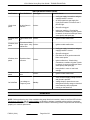
GENERAL
PROBLEM
POSSIBLE CAUSES
No spark to ignite pilot burner.
Spark at ignitor but pilot burner does not light.
Pilot burner will not stay lit.
1.
Power switch inoperative.
2.
No power to ignitor module.
3.
Ignition module not properly grounded.
4.
Spark gap incorrect.
5.
Ignitor/flame sense wire inoperative.
6.
Ignition module malfunction.
1.
No power to pilot solenoid valve.
2.
Pilot solenoid valve malfunction.
3.
Gas supply off or insufficient.
1.
Spark/flame sense wire connections
incorrect.
2.
Improper ground on pilot burner.
3.
Ignitor/flame sense malfunction.
4.
Gas pressure not within specified range; or
Incorrect gas type.
5.
Pilot flame needs adjusted.
1.
Power to temperature controller incorrect.
2.
Thermocouple malfunction.
3.
Temperature controller malfunction.
Pilot burner is lit but main burners will not light or maintain flame. 4.
High/Low heat.
Page 25 of 26
Gas pressure incorrect or incorrect gas type.
5.
Burner orifice obstructed or malfunction.
6.
Power to main burner valve incorrect.
7.
Main burner valve malfunction.
1.
Gas pressure incorrect; or incorrect gas
type.
2.
Burner orifice malfunction or incorrect. See
BURNER GAS ORIFICE CHECK.
3.
Air shutter not properly adjusted (radiant
burner only).
4.
Thermocouple malfunction.
5.
Temperature controller not properly
calibrated.
F45533 (1014)
VCCG Series Heavy Duty Gas Griddle - TROUBLESHOOTING
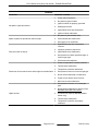
INFRARED BURNER
INFRARED BURNER
SYMPTOM
POSSIBLE CAUSE
Burner not lighting properly; or poor burner flame
appearance; or burner flame not orange.
1.
Orifice incorrect size or dirty.
2.
Incorrect gas pressure.
3.
Incorrect gas type.
4.
Orifice misaligned in venturi.
5.
Appliance not venting properly.
6.
Burner malfunction.
1.
Griddle with Infrared burner is mounted too close to
a fryer or charbroiler and the grease laden air is
causing burner ports to clog. If burner ports are
found to be clogged, install a replacement burner.
NOTE: Grease laden air is detrimental to the life of
the Infrared burner. If a technician sees a griddle
with Infrared burner mounted in a location close to
a fryer or charbroiler, please recommend to the
customer to move the griddle away from the grease
laden air source to prolong the life of the Infrared
burner.
Burner not lighting properly due to clogged ports.
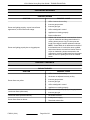
RADIANT BURNER
RADIANT BURNER
SYMPTOM
Burner flame too yellow.
Low burner flame (all burners).
Low burner flame (individual burner).
Burner flame floats on burner.
F45533 (1014)
POSSIBLE CAUSE
1.
Orifice incorrect size or dirty.
2.
Air shutter not adjusted correctly or dirty
3.
Incorrect gas pressure.
4.
Incorrect gas type.
5.
Orifice misaligned in venturi.
6.
Appliance not venting properly.
1.
Gas valve not adjusted properly or low gas pressure.
2.
Incorrect gas type.
1.
Air mixture incorrect.
1.
Inadequate air supply.
2.
Restricted exhaust flue.
Page 26 of 26