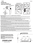
1
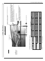
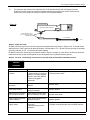
S82 W18717 Gemini Drive
PO Box 906
Muskego, WI 53150
Phone: (877) 622-2694
Fax:
(888) 679-3319
www.nabcoentrances.com
Gyro Tech Swing Door Conversion Unit (C.U.)
Hardware Installation and Service Manual
Bottom Load & Side Load
Swing Door Operators
Outswing Bottom Load Unit
Outswing Side Load Unit
Bottom Access
Panel
Hinged Side
Access Panel
DN 0270
WARNING
Do not install, operate or service this product unless you have read and understand the Safety Practices,
Warnings, Installation and Operating Instructions contained in this manual. Failure to do so
may result in property damage, or bodily injury.
Part # 15-10538
Rev 7-26-07
C.U. Swing Door Operator Installation Manual
Table of Contents
Page 3.......................................................Cautions
Page 4.......................................................Overview and Specifications
Page 5.......................................................Header Configurations
Page 6.......................................................Handing Requirements
Page 7.......................................................List of Materials
Page 8.......................................................Installing Bottom Load Header - Steps 1 to 5
Page 9.......................................................Bottom Load Header Installation Diagrams
Page 10.....................................................Installing Bottom Load Header - Steps 6 to 7
Page 11.....................................................Installing Bottom Load Header - Steps 8 to 9
Page 12.....................................................Installing Side Load Header - Steps 10 to 14
Page 13.....................................................Installing Side Load Header - Spindle Location Table
Page 14.....................................................Installing Side Load Header - Steps 15
Page 15.....................................................Installation of Arms and Tracks - Step 16
Page 16.....................................................Outswing Arm Lengths - Step 17
Page 17.....................................................Arm Pre-load on Analog or Magnum Controlled Units- Step 18
Page 18.....................................................Check Position Adjustments - Analog or Magnum Controls Units- Step 19
Page 19-20 ...............................................Micro Switch Cam Adjustment Illustrations - Analog or Magnum Controls
Page 20.....................................................Arm Pre-loading on “U” Series Controlled Units - Step 20
Page 21.....................................................Installing Door Stop, Wiring and Troubleshooting - Steps 21 to 22
Page 22.....................................................NABCO Entrances Return Policy
Page 2
www.NabcoEntrances.com
7-26-07
C.U. Swing Door Operator Installation Manual
CAUTIONS !
Read all of this First !
Read these safety practices before installing, operating or servicing the automatic door. Failure to follow these
practices may result in serious consequences.
Read, study and understand the operating instructions contained in or referenced in this manual before
operating. If you do not understand the instruction, ask the installing qualified technician to teach you how to use
the door.
Do not install, operate or service this product unless you have read and understand the Safety Practices,
Warnings, Installation and Operating Instructions contained in this manual. Failure to do so may result in
property damage, or bodily injury.
This manual and the owners’ manual must be given to and retained by the purchasing facility or end user.
1.
If the door appears broken or does not seem to work correctly, it should be immediately removed from
service until repairs can be carried out or a qualified service technician contacted for corrective action.
Never leave a door operating in an unsafe manner.
2.
Disconnect power at the fused disconnect during all electrical or mechanical service. When uncertain
whether power supply is disconnected, always verify using a voltmeter.
3.
All electrical troubleshooting or service must be performed by qualified electrical technicians and must
comply with all applicable governing agency codes.
4.
It is the responsibility of the installing door technician to install all warning and instructional labels in
accordance with ANSI 156.19 & ANSI 156.10 .
5.
It is the responsibility of the purchasing facility or end user to keep warning and instructional labels and
literature legible, intact and with the door.
6.
Replacement labels and literature may be obtained from local NABCO Entrances Inc. distributors. If
the name of the local distributor is unknown, contact NABCO Entrances Inc. at 1-877-622-2694 for
assistance.
7.
Do not place finger or uninsulated tools inside the electrical controller. Touching wires or other parts
inside the enclosure may cause electrical shock, serious injury or death.
7-26-07
www.NabcoEntrances.com
Page 3
C.U. Swing Door Operator Installation Manual
All installation changes and adjustments must be made by qualified, NABCO trained
technicians. The purpose of this manual is to familiarize the purchaser with the proper
installation and operation of a NABCO surface applied swinger system. It is essential
that this equipment be properly installed and operational before the door is used by
the public. The installed system must comply with all applicable standards. In the United States, ANSI Standard
156.10 for GT 400 or 8400 (refer to chart below) or ANSI 156.19 for GT 500 or 8500 covers these types of doors.
Other local standards or codes may apply. Use them in addition to the ANSI standard. The GT 400 or GT8400 and
GT 500 or GT8500 Model Units are listed with Underwriters Laboratory and are identified as such on the label.
TO THE
INSTALLER
Instruct the building owners and operator on the essentials of the operation of the door and this device. The owner
should follow these instructions to determine whether the door is operating properly and should immediately call for
service if there is any malfunction.
OVERVIEW
Gyro Tech Swing Door Conversion Unit (C.U.) operators are designed to be installed
to the surface of the door frame. The operator is controlled by either the Gyro Tech
Magnum or U series microprocessor based controllers or Model 1400 analog control.
These controllers offers many features to accommodate most installation options. This manual provides step by step
instructions to install the C.U. header and arm assemblies. Refer to your accompanying controller manual for information on wiring and adjusting the controller. Included in the controller manual you will find a trouble-shooting section
and optional wiring diagrams.
SPECIFICATIONS
Models:
Conversion Unit Models
Base Model
Conversion Unit
(CU)
Bottom Load
Conversion Unit
(CU)
Side Load
Model
Model
Full Automatic (mechanical closer)
GT 400
GT 8400
Low Energy (mechanical closer)
GT 500
GT 8500
Available controls:............................................................. Model GT-400 or GT-8400 is available with:
Magnum, U Series or Analog Control
Model GT-500 or GT-8500 is available with:
Magnum or Analog Control Only
Minimum Frame Face for Mounting.................................. 1 ¾” (44 mm)
Minimum Clearance from Top of ..................................... Bottom Load: 6 1/8” (156 mm)
Door to Ceiling
Side Load: 7 1/8” (181 mm)
Door Hinge Requirements ............................................... Butt, Offset Pivot, Center Pivot or Swing Clear Hinges
Door Thickness ................................................................ 1 ¾” (44 mm) Minimum
Door Width ....................................................................... Specify When Ordering
• Use of a supplemental door stop is always required.
Page 4
www.NabcoEntrances.com
7-26-07
C.U. Swing Door Operator Installation Manual
HEADER
CONFIGURATIONS
(See Figure 1)
The Gyro Tech CU (Conversion Unit) Swing Door Operator is available in two header configurations these are:
Bottom Load and Side Load.
Bottom load units have an access panel located on the bottom of the housing. Side load units have the access panel
located on the side of the unit. Both of these two header types are available for full automatic or low energy systems.
Full automatic units are power opened, spring closed. They employ sensors and once adjusted optimally will conform
to ANSI 156.10. They are available with Magnum, “U” series or Analog controls.
Low energy units are used for barrier free access. They are power opened, spring closed, are usually activated with
push button switches and once adjusted optimally will conform to ANSI 156.19. They are available with Magnum or
Analog controls.
Access Panel Locations
Figure 1
GT400 and GT500
Outswing Bottom Load Unit
Surface Mount
Operator
Housing
GT400 and GT500
Inswing Bottom Load Unit
Surface Mount
Operator
Housing
GT8400 and GT8500
Outswing Sideload Unit
Surface Mount
Operator
Housing
Access
Panel
Hinged Access
Panel
Access
Panel
Inswing Arm
Outswing
Arm and Rod
Assembly
Surface
Mount
Track
Outswing
Arm and Rod
Assembly
DN 0270
7-26-07
www.NabcoEntrances.com
Page 5
C.U. Swing Door Operator Installation Manual
HANDING
REQUIRMENTS
The Figure 2 below illustrate the various methods of handing
Figure 2
Left Hand (LH) Inswing
Right Hand (RH) Inswing
Inswing track
Inswing arm
EXTERIOR
Right Hand (RH) Outswing
Left Hand (LH) Outswing
Arm mounting
bracket
Outswing Arm
EXTERIOR
DN 0270
Note: The hand of the unit must match the hand of the door. To determine the hand of the unit refer to the end flap of
the cardboard carton that contains the header housing assembly. Refer also to the serial number stamp on the underside of the operator. The first letter of the serial number will indicate the “hand” of the operator. For example,
L2G755640 indicates that the operator is a left hand unit. R2G755640 indicates that the operator is a right hand unit.
Refer to Figure 3 below.
Figure 3
NABCO
ENTRANCES
GYRO TECH
S82 W18717 Gem ini Drive
Mus kego, WI 53150 USA
Serial Number
L R 579726
Operator serial numbers begins with a letter.
The letter not punched out indicates the hand
of the operator. For instances, if an “R” is
visible, the operator is a Right Hand unit.
Page 6
DN 0276
www.NabcoEntrances.com
7-26-07
C.U. Swing Door Operator Installation Manual
Below is a table of the major components that comprise a
LIST OF
MATERIALS
GT-400/8400 or GT500/8500 Installation.
ITEM 1
ITEM 5
ITEM 3
21-8848 Outswing Arm Assembly
ITEM 6
41-8987-01
41-8987-02
LH Operator for U Series Control
RH Operator for U Series Control
21-0997 Inswing Track Assy. (12.25”)
21-0998 Inswing Track Assy. (21”)
ITEM 4
ITEM 2
21-0902 Inswing Arm.
ITEM 11
11-1391
11-1390
LH Clutchless Operator for Magnum Ctrl.
RH Clutchless Operator for Magnum Ctrl.
LH Operator for Magnum Ctrl.
RH Operator for Magnum Ctrl.
LH Clutchless Operator for Analog Ctrl.
RH Clutchless Operator for Analog Ctrl.
LH Operator for Analog Ctrl.
RH Operator for Analog Ctrl.
21-3568
21-3570
21-3567
21-3569
OFF
AUTO
H.O.
EXIT
OFF
AUTO
H.O.
DN 0145
41-2342 Control, GT300 & GT500 OS - Canada
ITEM 7 ITEM 8 ITEM 9 ITEM 10
ON
Inswing Arm Assy LH, 204
Inswing Arm Assy LH, 313
Inswing Arm Assy RH, 204
Inswing Arm Assy RH, 313
41-1512 Control, GT300 & GT500 OS - USA
ITEM 13
OFF
OPEN
ON
OFF
ITEM 14
DOOR OPERATION
41-8987-07
41-8987-08
41-8987-09
41-8987-10
H.O.
41-2208 Control, GT500 Slow Mode - USA
41-3429 Control, GT500 Slow Mode - Canada
ITEM 16
ON
ON
OFF
OFF
ITEM 12
OFF
STOP
HOLD-OPEN
F1
EXIT
AUX
PWR
TDPG
BCHK
OPEN
TDAS
CLOSE
RED
LCHK
Fuse 1: 0.5A 24 VAC
LED
BLACK
SIGNAL
INPUT
22-1772-05
Momentary
Key Switch
J2
10-3528
Rocker
Switch
HOLD OPEN
J1
TRANSFORMER
AC IN
J4
4
22-11350
Rocker
Switch
R28
3
22-1772-04
Key Switch
2
22-1772-03
Key Switch
O 1
F
F
10-3527
Rocker
Switch
SW2
CURRENT
LIMIT
MOTOR
J5
SW1
CAPACITOR
RELAY
RELAY
F2
Fuse 2:FUSE
3A 120/240
21-9823
Rocker
Switch
Model/Control
Rocker Switch
ITEM #
DN0033
12-10292 Magnum Control with Brake Module
Outsw.
Arm Assy.
ITEM #
Inswing
Arm Assy.
ITEM #
Control
ITEM #
Motor/Gearbox
ITEM #
ITEM 15
GYRO TECH - 248901.10
No.
MICROPROCESSOR CONTROLLER
POWER SOURCE (4P)
GT-400 U Series
13 or 14
5
3 + 4 or 6
15
1
GT-400 Magnum
7, 8, 9, 10, or 16
5
3 + 4 or 6
12
2
GT-400 Analog
7, 8, 9, 10, or 16
5
3 + 4 or 6
11
2
GT-8400 U Series
13 or 14
5
3 + 4 or 6
15
1
GT-8400 Magnum
7, 8, 9, 10, or 16
5
3 + 4 or 6
12
2
GT-8400 Analog
7, 8, 9, 10, or 16
5
3 + 4 or 6
11
2
GT-500 Magnum
7, 8, 9, 10, or 16
5
3 + 4 or 6
12
2
GT-500 Analog
7, 8, 9, 10, or 16
5
3 + 4 or 6
11
2
GT-8500 Magnum
7, 8, 9, 10, or 16
5
3 + 4 or 6
12
2
GT-8500 Analog
7, 8, 9, 10, or 16
5
3 + 4 or 6
11
2
7-26-07
MAGNUM IV
www.NabcoEntrances.com
NO. COLOR
1
2 WHITE
3 BLACK
4
OPERATOR (6P)
NO.
1
2
3
4
5
6
COLOR
RED
ORANGE
BROWN
BLUE
BLACK
YELLOW
HANDY TERMINAL (6P)
USE
EMPTY
115VAC COMMON
115VAC HOT
EMPTY
USE
MOTOR V PHASE
ENCODER 12VDC
ENCODER A PHASE
MOTOR U PHASE
ENCODER GND
ENCODER B PHASE
SENSOR (12P)
FUSE INSIDE
RATING:125V, 4A
SIZE:5.2 x 20mm
WARNING
For continued protection
against fire, replace only
with same type and rating
of fuse.
CAUTION
USE [SLIDER/SWINGER]
12VDC +
12VDC -,COMMON
APPROACH
THRESHOLD SENSING
/PRESENCE SENSOR
REDUCED OPENING
/SAFETY MAT
ORANGE MODE SW1
ORANGE MODE SW2
ORANGE APPROACH(THROUGH)
YELLOW SEQUENTIAL
BREAK OUT
BLUE
VIOLET
OUTPUT +
GRAY
OUTPUT -
NO. SYMBOL COLOR
1 9DC12V BROWN
2 7
RED
3 61
BLACK
4 6B
WHITE
5
H
6
7
8
9
10
11
12
M0
M1
62
SQ
BA
OUT +
OUT -
GREEN
1.Please adjust this operator as per instruction manual.
2.Turn the power off, before opening the box.
3.Don't open this box except for replacing fuse.
Otherwise, the warranty will be terminated.
4.Repair of this unit except by Nabco Entrances, Inc.
may cause software and hardware malfunction.
24-8901 U Series Control
Page 7
C.U. Swing Door Operator Installation Manual
INSTALLATION:
Steps 1 to 9
Bottom Load
Steps 10-15
Side Load Unit
Steps 16-22
Both
BOTTOM LOAD
ONLY
Step 1 - Remove material from packages and check contents:
Remove all contents from the carton. Check all items to ensure you have the material you need before beginning the
actual installation.
Step 2 - Remove access panel from header housing assembly:
Carefully remove the header housing assembly from the cardboard carton. Using a Phillips screwdriver, remove the
Access Panel (see Fig 1 on page 5). Use a pencil to mark the locations of the Access Panel Mounting Brackets. This
will make it easy to place the brackets back in the correct position when re-installing the Access Panel. Refer to Figure 5 below.
Mark the location of the Access Panel Mounting Brackets with a pencil
Note that when reinstalling the brackets, that the tabs on the brackets
should be facing downward.
Figure 5
Step 3 - Remove paperwork:
DN 0078
Remove all decals, paperwork and parts bag from inside header and set to one side.
Step 4 - Install wiring in frame:
All conduit and switch or sensor wires must be pulled through the frame or wall before mounting the operator housing.
Refer to your separate Controller Installation Manual for wiring instructions.
Step 5 - Mount header housing assembly on door frame:
Refer to figures on next page. The following instructions refer to mounting the unit on aluminum framing. If the unit is
not being installed on an aluminum frame then adequate structural framing must be available for mounting.
Note: There is a difference in the location of the operator spindle between inswing and outswing header housing assemblies. Therefore the width of the base pivot plate on which the operator is mounted is varied according to the type
of door; inswing, outswing, with or without finger guard, etc. Refer to Figure 7 Page 9. To ensure you are matching
the correct header housing to the door you are working on, refer to the table on the above mentioned page.
Once all wiring is in place, using the empty header mounting brackets as a template, hold the header against the
frame, and mark the mounting holes on the jamb tubes as shown on the following page. Ensure bottom of header
housing assembly is 1-1/8” up from the top of the door as shown in Figure 6 on Page 9. The center line of the three
holes on the end mounting brackets must be located one (1) inch away from the edge of the door frame as shown.
NABCO recommends the use of Rivnuts when mounting the header to aluminum framing. Using a #Q sized drill bit
(0.332 DIA), drill out the four holes per bracket in the jamb tubes and countersink the holes 0.531 DIA x 100o and insert the supplied Rivnuts. Using a Rivnut setting tool, expand the Rivnuts in the aluminum frame until they are “snug”.
Caution!
Over tightening the Rivnuts will cause the threads to strip.
Once all holes are properly drilled and Rivnuts installed, mount header housing to frame using the six 1/4-20 x 1” flat
header screws provided. Affix the tape onto the end caps and mounting brackets to cover the mounting screws and
end cap screws.
NABCO recommends the use of Rivnuts when mounting the header to aluminum framing. On other types of installations such as hollow metal door frames, adequate backing such as 2” x 10” wood backing is required above the top of
the frame for anchoring the header housing to the wall. Using this method would require lag bolts instead of 1/4 x 20
Rivnuts to properly anchor the unit.
Page 8
www.NabcoEntrances.com
7-26-07
7-26-07
Figure 6
A = Base Plate dimension
B = Spindle Location
B
A
www.NabcoEntrances.com
Butt/Offset
Center Pivot
Butt/Offset
Center Pivot
GT-400
GT-500
Notes: N/A = Not Applicable
Pivot Type
Model
N/A
6"
N/A
3-1/2"
5"
5"
2-1/2"
2-1/2"
A
N/A
6"
N/A
3-1/2"
5"
5"
DN 0270
DN 0270
Figure 8
Rivnuts must be
used to secure
housing to
aluminum framing.
Mark holes for
mounting screws.
Drill out holes and
securely fasten to
structural framing.
Base Plate
varies with door
configuration
(refer to chart below)
Figure 7
2-1/2"
2-1/2"
Outswing
With Fingerguard
No Fingerguard
B
A
B
A
Spindle Loc.
Base Plate
Spindle Loc.
Base Plate
N/A
N/A
7-1/4"
4-3/4"
8-1/4"
5-3/4"
7-1/4"
4-3/4"
Spindle Locations and Base Pivot Plate Sizes
Inswing
With Fingerguard
No Fingerguard
B
A
B
A
Spindle Loc.
Base Plate
Spindle Loc.
Base Plate
N/A
N/A
5"
2-1/2"
6"
3-1/2"
5"
2-1/2"
C
B
Position the end of the housing assembly
to line up with the inner edge of the jamb
tube (on the pivot side) as shown.
1-1/8” between top of door and
underside of housing assembly.
Note: this dimension is to
accommodate INSWING units.
Outswing units can be lowered
provided the arm has an
appropriate place to mount on the
top rail of the door.
1" from inner
edge of pivot
jamb to center
line of holes
Note:
The illustrations on this page depict an installation to an aluminum door and
frame. On other types of installations such as hollow metal door frames,
adequate backing such as 2” x 10” fir or spruce to provide structural framing is
required above the top of the frame for anchoring the header housing to the
wall. Using this method would require lag bolts instead of 1/4 x 20 Rivnuts to
properly anchor the unit.
DN 0270
Drill 25/64” diameter holes in jamb tube
and insert Rivnuts for affixing housing
assembly to aluminum framing or securely
fasten to structural framing
BOTTOM LOAD ONLY
C.U. Swing Door Operator Installation Manual
Page 9
C.U. Swing Door Operator Installation Manual
BOTTOM LOAD ONLY
Step 6 - Install wires in header housing assembly:
Bring wires into housing assembly from lock side of header if possible since this is the side that is closest to the controller. Wires can be routed through the knockouts located at either end on the top of the header assembly. Using the
supplied metal clips, route all loose wires through channels in header housing assembly and snap into place in channel as illustrated in Figure 10 below.
Step 7 - Install stop ring on operator:
Refer to Figure 9 below. Once all wires are in place, the operator and controller can be mounted in place in the
header housing assembly. Place operator on bench with the underside facing up as shown in Figure 9. Remove the
Stop Ring Assembly from the plastic bag and it install on the operator using the supplied brackets and the (4) 5/16-18
FL. HD. Soc. Mach. Screws. Do not tighten the screws all the way down until the operator is installed in the header
housing assembly and the arm is installed.
Stop Ring
Figure 9
Front Mount Pins
Serial Number
Front Mounts
DN 0276
Rear Mount
Lovejoy coupling access
hole for bottom load
operators.
Acc
Stop Ring Brackets
A similar hole is located
on the top side of the
operator for side load units
also.
es s
pan
el re
mov
ed
f or c
larity
Figure 10
Wire Harness
Snap Clip
In Place
Controller
Mounting Clip
Steel clip
DN 0270
Access Panel to Housing Assembly
Page 10
www.NabcoEntrances.com
7-26-07
C.U. Swing Door Operator Installation Manual
BOTTOM LOAD ONLY
Step 8 - Install operator in header housing assembly:
If installing Analog control it might be necessary to mount a soft start capacitor on the operator prior to installing it in the
header housing assembly. Refer to your Controller Installation Manual for additional information. Using a 9/16” deep
socket and ratchet, remove the nuts and washers from the operator mounting bracket inside the header housing assembly. Place them on the top of the installed header housing assembly for easy reach. Holding the operator at an angle as shown in Figure 11 below, slip the operator Front Mounts over the pins and the Rear Mounts over the operator
mounting brackets. Holding the operator up in place, install the two 9/16” flat washers and nuts on to the mounting
bracket studs and tighten securely. Figure 12 illustrates an installed operator. Once installed, the operator spindle
should be located at the correct distance from the jamb as shown in the dimensions chart on page 9.
Figure 11
Figure 12
Tabs on the
brackets should be pointing
downward.
Front Mounts on operator cover
Pivot Base Tabs
NABCO
ENTRANCES INC.
R3J724456
DN 0270
Ensure that the switch harness is tucked between housing assembly and operator mounting bracket
DN 0270
Step 9 - Install control mounting clip and controller:
Snap controller mounting clip into housing extrusion and then snap control into mounting clip. Refer to figure 10 & 13.
Note: Magnum or “U” series controls used on simultaneous pairs require two controls and mounting clips. .
Figure 13
U Series Control
Controller
Mounting Clip
DN 0140
Magnum Control
DN 0139
7-26-07
www.NabcoEntrances.com
Page 11
C.U. Swing Door Operator Installation Manual
INSTALLATION:
SIDE LOAD
ONLY
Steps 1 to 9
Bottom Load
Steps 10-15
Side Load Unit
Steps 16-22
Both
Step 10 - Remove material from packages and check contents:
Remove all contents from the carton. Check all items to ensure you have the material
you need before beginning the actual installation. Refer to Figure 4 for an illustration of the
components that make up a typical C.U. system.
Step 11 - Remove access panel from header housing assembly:
Carefully remove the header housing assembly from the cardboard carton. Using a Phillips screwdriver, remove the
two Access panel retaining screws, refer to Figure 14 on the following page.
Step 12 - Remove paperwork:
Remove all decals, paperwork and parts bag from inside header and set to one side.
Step 13 - Install wiring in frame:
All conduit and switch or sensor wires must be pulled through the frame or wall before mounting the operator housing.
Refer to your separate Controller Installation Manual for wiring instructions.
Step 14 - Mount header housing assembly on door frame:
Refer to Figure 14 on next page. The following instructions refer to mounting the unit on aluminum framing. If the unit
is not being installed on an aluminum frame then adequate structural framing must be available for mounting.
Once all wiring is in place, drill two or three 1/4” holes through the back of the header housing to securely mount in
place. These holes will be used to mount the header housing to the jambs. Wires can be routed out through the face
of the jamb and into the back of the header housing. Alternatively, the unit can be ordered with knockouts located at
either end on the top of the header assembly that can be used to route wires into.
Note: It might be necessary to remove the operator and motor assembly from the housing to reduce the weight of the
unit while positioning the unit on the frame to be mounted.
Note: There is a difference in the location of the operator spindle (on which the arm is mounted) between inswing and
outswing header housing assemblies. Therefore, the position of the operator spindle is varied according to the type of
door, be it inswing, outswing, with or without finger guard, etc. To ensure you are matching the correct header housing to the door you are working on, refer to the table titled “GT-8400 and GT-8500 - Spindle Locations” on the following page.
Once holes are drilled, position the header housing on door frame so that the bottom of the header housing assembly
is located 1-1/8” up from the underside of the door frame as shown in Figure 14. Using a pencil, scribe the holes for
drilling the jamb tube.
Remove header housing. Using the penciled circles for guides, drill the jamb tubes using a #Q sized drill bit (0.332
DIA), and countersink the holes 0.531 DIA x 100º. Insert the supplied Rivnuts. Using a Rivnut setting tool, expand the
Rivnuts in the aluminum frame until they are “snug”.
Caution!
Over tightening the Rivnuts will cause the threads to strip
Once all holes are properly drilled and Rivnuts installed, mount header housing to frame using the six 1/4-20 x 1” flat
header screws provided.
NABCO recommends the use of Rivnuts when mounting the header to aluminum framing. On other types of installations such as hollow metal door frames, adequate backing such as 2” x 10” wood backing is required above the top of
the frame for anchoring the header housing to the wall. Using this method would require lag bolts instead of 1/4 x 20
Rivnuts to properly anchor the unit.
Page 12
www.NabcoEntrances.com
7-26-07
7-26-07
Note:
Rivnuts must be used
to secure housing to
aluminum framing.
Figure 14
www.NabcoEntrances.com
Notes:
N/A = Not Applicable
Center Pivot
Butt/Offset
6"
N/A
6"
Center Pivot
GT-8500
N/A
Butt/Offset
5"
5"
5"
5"
Spindle Loc.
Spindle Loc.
GT-8400
No Fingerguard
6"
N/A
8-1/4"
N/A
Spindle Loc.
5"
5"
7-1/4"
7-1/4"
Spindle Loc.
No Fingerguard
Outswing
With Fingerguard
Dimension “B”
1-3/4” Standard Overlap
1-1/8” between top of door and underside of housing assembly.
Note: this dimension is to accommodate INSWING units.
Outswing units can be lowered provided the arm has an
appropriate place to mount on the top of the door.
Door Stop
Access panel retaining screw
Drill 1/4” holes through back of housing to securely mount header. Position
housing on door frame and, using a pencil, mark holes for drilling jamb tube
behind. Remove housing and using marked holes for guides, drill 0.332”
diameter holes through jamb tube. Insert and expand Rivnuts into jamb
tubes and mount housing on frame as shown.
If mounting to a wall, adequate backing is required for bolting the unit tot he
wall. Use lag bolts or a similar system for anchoring.
Position the end of the housing assembly to line up with edge of the 1-3/4”
jamb tube (on the pivot side) as shown.
With Fingerguard
Pivot Type
Inswing
“B”
Spindle location dimension
varies with door configuration
Model
GT-8400 and GT-8500 - Spindle Locations
DN 0279
Coupling Access Hole
Side Load Header Only
SIDE LOAD ONLY
C.U. Swing Door Operator Installation Manual
Page 13
C.U. Swing Door Operator Installation Manual
SIDE LOAD ONLY
Step 15 - Install operator in header housing assembly (if removed):
Position operator and motor assembly inside header housing assemble and secure from the bottom with
four (4) 5/16-18 flat head screws as shown in Figure 15 below.
Once installed, the operator spindle should be located at the correct distance from the jamb as shown in the
dimensions chart on page 13.
Figure 15
Secure operator through
underside of housing with
four (4) 5/16-18 flat head
screws supplied.
Auxiliary Door Stop
DN 0279
Page 14
www.NabcoEntrances.com
7-26-07
C.U. Swing Door Operator Installation Manual
Step 16 - Installation of Arms and Tracks:
(ALL MODELS)
On outswing doors, remove the arm mounting bracket (refer to Figure 2 page 6) from the outswing arm assy. and install on door as shown below. On inswing units, remove the inswing track (refer to Figure 2 page 6) from box and install
on door as shown below (do not install the arm on to the operator spindle at this time).
Dimension "C" - Outswing Arm Mounting Locations
Distance From Inside Edge of Pivot Jamb to Center Line of First Arm Bracket Mounting Hole
Outswing
Model
Pivot Type
With Fingerguard
No Fingerguard
GT-400 & GT-8400
Butt/Offset
Center Pivot
Not Applicable
16"
12-7/16"
15"
GT-500 & GT-8500
Butt/Offset
Center Pivot
Not Applicable
13-3/4"
10-3/16"
12-3/4"
Attach arm bracket to door using
1/4" - 20 F.H.M.S. (use Rivnuts or
Nutserts or reinforce door)
Operator spindle
Bottom load header
shown, same for side
load
1-1/8" from top of door
to bottom of housing
assy.
1-1/2”
Dimension B
Dimension C
DN 0270
Dimension "C" - Inswing Track Mounting Locations
Distance From Inside Edge of Pivot Jamb to Center Line of First Mounting Hole
Model
GT-400 & GT-8400
Inswing Standard Track (ST) 11-1/4"
With Fingerguard
No Fingerguard
Pivot Type
Butt/Offset
Center Pivot
GT-500 & GT-8500
Butt/Offset
Center Pivot
Inswing Panic Track (PT) 20-1/16"
With Fingerguard
No Fingerguard
Not Applicable
8-1/4"
Not Applicable
Not Applicable
13"
12"
3-3/4"
2-3/4"
Not Applicable
8-1/4"
Not Applicable
Not Applicable
13"
12"
3-3/4"
2-3/4"
Attach arm bracket to door using
1/4" - 20 F.H.M.S. (use Rivnuts or
Nutserts or reinforce door)
Bottom load header
shown, same for side
load
Dimension B
1-1/8" from top of door
to bottom of housing
assy.
Dimension C
11/16” if using straight
arm for 0” reveal
1-9/16” if using “L”
shaped arm for all
other reveals
DN 0270
7-26-07
www.NabcoEntrances.com
Page 15
C.U. Swing Door Operator Installation Manual
Step 17 - Outswing Arm Lengths:
Using the chart below, determine the appropriate length of the outswing arm (dimension “D”) and cut the supplied
threaded rod to suit. Measure and cut the supplied plastic arm cover to suit rod length and slide over threaded rod.
Assemble arm as shown in Figure 16 below.
Figure 16 (Plan View) Determining Dimension “D”
Door
Frame
Arm
Reveal
(distance from
face of door to
back side of
housing
assembly)
Housing Assembly
(Bottom Load shown)
“D”
DN 0270
Dimension “D” Outswing Arm Length
Distance from Center Line of Arm Elbow to Center Line of Bolt on Door Bracket
Reveal
Model
Pivot Type
1-1/8”
2-1/8”
3-1/8”
4-1/8”
5-1/8”
6-1/8”
GT-400 & GT-8400
Butt/Offset
11-7/8”
12-7/8”
13-7/8”
14-7/8”
15-7/8”
16-7/8”
Center Pivot
12-1/2”
13-1/2”
14-1/2”
15-1/2”
16-1/2”
17-1/2”
Butt/Offset
11-7/8”
12-7/8”
13-7/8”
14-7/8”
15-7/8”
16-7/8”
Center Pivot
11-7/8”
12-7/8”
13-7/8”
14-7/8”
15-7/8”
16-7/8”
GT-500& GT-8500
Page 16
www.NabcoEntrances.com
7-26-07
C.U. Swing Door Operator Installation Manual
Step 18 - Arm Pre-load on Magnum or Analog Controlled Units:
(if installing a unit with a “U” series microprocessor skip to Step # 20)
Refer to Figures 17 & 18 below. In order to achieve correct back check and latch positions, the operator must be preloaded (spring wound up before the arm is affixed to the door) by approximately 130 - 140 º. This also rotates the
cams (located on the top of the operator) around to the required position to open and close the micro switches at the
correct point of door travel. With door closed and arm connected to the door, the scribe mark on the underside of the
operator spindle should be parallel with the door.
To properly pre-load operator and set arm in correct location on spindle, perform the following steps:
a. Be certain operator/motor is plugged into controller.
! WARNING !
The controller has an electrical circuit built in to slow the rotation of the operator arm while it is
unwinding. Removing the pin while the motor is unplugged from the controller will allow the
spindle and arm to unwind at high speed and can result in personal injury or damage. Great care
must be taken not to dislodge pin or otherwise release the operator and arm unless the motor is
properly plugged in to the controller.
b.
c.
d.
e.
f.
g.
h.
With the operator fully unwound and the arm uninstalled, the position of the micro switch cam would be as
shown in Figure 19 on the following page.
Install the arm on the operator spindle in the unwound position.
While tightly holding the arm, wind up the operator approximately 60 degrees.
On bottom load units, insert a 1/8” Allen wrench or similar tool into the Lovejoy coupling access hole located
on the bottom of the operator at the motor end. Refer to Figure 9.
On side load units, insert a 1/8” Allen wrench or similar tool into the Lovejoy coupling access hole located on
the top of the operator at the motor end. Refer to Figures 9 and 14. This will pin the motor and operator in the
correct position and prevent them from unwinding.
Remove the arm, rotate it “minus” 60 degrees and reinstall it again. While holding arm, remove pin, wind up
the spindle 60 degrees again and re-pin the operator. Repeat this process in increments of approximatley 60
degrees to achieve the necessary fully loaded position of 130-140 degrees. It might be possible to wind the
arm more than 60 degrees at a time, if so, that is acceptable.
Inspect scribe mark on the underside of the spindle. With door closed and arm connected to the door, the
scribe mark on the underside of the operator spindle should be parallel with the door.
Once item (f) is confirmed, tighten set screw on the arm. Ensure the set screw on the arm is seated
correctly in the groove on the operator spindle. Refer to Figure 23 on page 21.
Once the arm is connected to the operator spindle, connect the other end of the arm to the door bracket or
track. Note: the easiest way to install the inswing arm into the track is to remove the 1/4”-20 screw from one
end of the track and let it swing down. Allow the roller to contact and push againist the door and then swing
the track back up so that the roller is inside the track and re-install the screw.
Figure 17
Pre-loading a LH Inswing Operator
Arm in
Unwound
Position
70-80°
60°
Figure 18
Pre-loading a RH Outswing Operator
Wind arm
in 60º
increments
Arm in Wound Position
Arm in
Unwound
Position
Bottom Load Housing Assy.
Shown
70-80°
Arm in Wound Position
60°
Wind arm
in 60º
increments
DN 0270
7-26-07
www.NabcoEntrances.com
Page 17
C.U. Swing Door Operator Installation Manual
Figure 19
Position of the adjustment cam in the fully unwound position on left and right hand operators.
Magnum or Analog Controlled Units Only
Latch Check Switch Wires
Magnum Control: White & Green
Analog Control: Orange & Brown
Figure 19
Position of cam on LEFT
Hand operator shown with
spring FULLY UNWOUND
Back Check Switch Wires
Magnum Control: Red & Blue
Analog Control: Yellow, White & Blue
Back Check Switch Wires
Magnum Control: Red & Blue
Analog Control: Yellow, White & Blue
Position of cam on RIGHT
Hand operator shown with
spring FULLY UNWOUND
Latch Check Switch Wires
Magnum Control: White & Green
Analog Control: Orange & Brown
DN 0270
Step 19 - Check Position Adjustments on Analog or Magnum Controlled Units:
Once the unit is mounted, the operator, control and arm is installed and the other half of the arm affixed to the door,
the door can be used manually. To verify correct operator pre-load or check/change the desired position at which the
door will go into back check and latch check, apply power to the units taking care to correctly connect the 120 VAC as
outlined in the controller installation manual. Activate the unit. The door should go open, time out and close smoothly.
If adjustment of check positions are required, perform the following steps:
On a GT-400/500 Bottom Load Conversion Unit (CU):
Only the back check cam is adjustable on a bottom load unit. Refer to Figure 20 on the following page. The cam assembly can be adjusted through an access hole located on the top of the header housing. Remove the plastic snap in
cover and observe the micro switches and cam on the top of the operator. The position at which the door is switched
into back check can be varied by rotating the cam shown in Figure 20. The rotation of this cam is adjustable by removing the black “set screw” and placing it in the adjustable position as shown. Then, by loosening the “cam hold
down screw” and rotating the cam, the point at which the door is switched into back check can be varied (this applies
to Magnum or Analog controlled systems only – the U series microprocessor does not use switches to control back
check and latch positions).
On a GT-8400/8500 Side Load Conversion Unit (CU):
Refer to Figure 21 on the following page. The cam assembly must be accessed from inside the header housing assembly. Using a 5/16” box or open end wrench, loosen the cam hold down screw. Using a 1/4” open ended wrench,
loosen the cam set screw and rotate the top cam to adjust the back check position or the bottom cam to adjust the
latch check position. This applies to Magnum or Analog controlled systems only. The U series microprocessor does
not use switches to control back check and latch positions.
Note: Both the back check and the latch check positions can be varied.
Page 18
www.NabcoEntrances.com
7-26-07
C.U. Swing Door Operator Installation Manual
Bottom Load Unit Only - Adjustment of Back Check Cam is made with Phillips Screwdriver from TOP of the Header
Magnum or Analog Controlled Units Only
The illustration below shows the procedure for repositioning the cam set screw to vary back check positions.
To adjust, insert screw driver from top and loosen screws.
Cam set screw with
Phillips head
in fixed factory position
Figure 20
Short arm panic breakout
micro-switch
Set screw is moved
here for the
adjustable position
Cam hold
down screw with
Phillips head
DN 0275
Back check and
Latch check
Micro-switches
DN 0274
Side Load Unit Only - Adjustments of Back and Latch Check Cams are made with Wrench from SIDE of the Header
Magnum or Analog Controlled Units Only
The illustration below shows the procedure for repositioning the cam set screw to vary back check and
latch check positions. To adjust, insert wrench from side and loosen screws.
Set screw with 1/4”
Hex Head located in
adjustable position
Figure 21
Short arm panic breakout
micro-switch
Cam hold
down screw with
Hex head
DN 0273
need a new picture from
John. change this illustration.
Back check and
Latch check
Micro-switches
DN 0271
Notes:
The Latch Check and Back Check switches illustrated above are not used with the “U” Series control.
The short arm micro-switch is a panic breakout switch used on all inswing units.
7-26-07
www.NabcoEntrances.com
Page 19
C.U. Swing Door Operator Installation Manual
(Magnum or Analog controls only) Figure 22 below illustrates the correct position of the switch cams in the door
CLOSED and door OPENED positions with the operator pre-loaded 130º - 140º.
Figure 22
Back Check Switch
Breakout Switch
Right Hand operator shown in
DOOR CLOSED position.
Latch Check Switch
ACUGARD limit switch (if used)
Back Check Switch
Breakout Switch
Right Hand operator shown in
DOOR OPENED position.
Latch Check Switch
Latch Check Switch
Left Hand operator shown in
DOOR CLOSED position.
Back Check Switch
Breakout Switch
Latch Check Switch
Left Hand operator shown in
DOOR OPENED position.
Back Check Switch
Breakout Switch
DN 0277
Step 20 - Arm Pre-loading on “U” Series Controlled Units:
The NABCO “U” Series Control keeps track of the door’s position via the motor encoder. Therefore the degree of preload is not as crucial as with the Magnum or Analog control. The degree of pre-load on the operator arm is at the
discretion of the installer. More pre-load can be applied when more closing force is desired. Once the control is
powered up and the door is programmed for stroke via the Handy Terminal, the position of the door and arm is saved
in the memory of the U Series Controller. To install the arm on the spindle, perform the following steps:
a.
Be certain operator motor is plugged into controller.
! WARNING !
The controller has an electrical circuit built in to slow the rotation of the operator arm while it is
unwinding. Unplugging the operator from the controller once the arm is wound up will allow the
spindle and arm to unwind at high speed and can result in personal injury or damage.
Page 20
www.NabcoEntrances.com
7-26-07
C.U. Swing Door Operator Installation Manual
b.
For minumum door closing force: Install the arm on the operator spindle with a 45 degree pre-load.
Install and connect control as Controller Installation Manual and program door stroke. Ensure the set
screw on the arm is seated correctly in the groove on the operator spindle.
Figure 23
Operator and Motor Assembly
Ensure that set screw on
arm is seated in groove on
operator spindle
Arm Assembly
DN 0270
Step 21- Install door stop:
On Side Load Units, open door to the full open point and position door stop shown in Figures 14 & 15 so that it butts
against the arm. Using a pencil mark the hole positions. Drill and tap for 1/4” - 20 bolts. Secure arm stop to underside
of housing with two (2) 1/4” - 20 round head screws supplied.
On Bottom Load Units, loosen stop ring brackets shown in Figure 9 on page 10, open door to the full open point and
rotate the door stop so that it butts against the arm and tighten stop ring bracket retaining screws.
Step 22 - All units - Install wiring, and sensors as per the separate Controller Installation manual.
TROUBLE
SHOOTING
Symptom
Operator does not
function.
Action/Cause
Door is staying open on
activation
Spring is broken in the
operator
Replace spring
Door slams closed.
Clutch gear or woodruff keys
slipping in operator
Replace operator
Motor spins on activation
but door does not open
Check polarity of motor input
wires at connector on motor.
Reverse motor leads.
Door begins to open then
closes suddenly
Clutch gear or woodruff keys
slipping in operator
Replace operator
Door does not stay
tightly closed.
1. Preload on swing arm is
not correct.
2. Building stack pressure
excessive.
7-26-07
Solution
1. Gears slipping or binding in
operator or coupling slipping
between motor and operator
2. Motor is plugged in
backwards
1. Re-secure or free up gears or couplings
2. Reverse motor leads
1. Set pre-load on arm as explained on page 17
2. Replace clutched operator with clutchless operator
www.NabcoEntrances.com
Page 21
C.U. Swing Door Operator Installation Manual
NABCO Entrances Return Policy - Limited Warranty
NABCO ENTRANCES INC. for its Gyro Tech product line, provides to its distributor a limited
warranty, on Gyro Tech products. This warranty is:
NABCO ENTRANCES INC. will exchange or repair, F.O.B. the plant, any component found defective in
workmanship and/or material, subject to Nabco’s inspection, for a period of one (1) year after installation or
18 months after manufacture, whichever comes first. Warranty does not include field service labor. The
installing contractor/distributor will be responsible for installation and field service. This is NABCO
ENTRANCES Inc.’s sole warranty.
This warranty does not cover loss or damages resulting from causes beyond the manufacturer's control, misuse,
neglect, accidents, windstorms, or other acts of God, or acts of terrorism. Warranty is for normal use and service.
The warranty does not apply to equipment that has been repaired or altered so as to adversely affect conditions of
operation. Warranty will not obligate NABCO for damages resulting from such alterations, misuse, or acts of God, or
acts of terrorism.
Extended Warranties - New Parts and Equipment Only
Two-year warranties on all Gyro Tech entrance systems are available. The two (2) year warranty is the same as the
one (1) year warranty except for a period of two (2) years after installation or 30 months after manufacture whichever
comes first. All orders requesting a multi year warranty must be included on the purchase order at the time of the
original order to establish proper records. Any other extended warranty must be specifically approved and priced by
NABCO Management.
Warranty Seal on Operators
All operators will contain a warranty seal placed over the cover and housing. The warranty will become invalid if any
operator is returned with the seal broken.
Return of Warranty Parts
NABCO must be promptly notified (within 2 weeks of failure) of all warranty claims. All parts for warranty claims must
be returned to NABCO within the following two (2) weeks for US locations and six (6) weeks for all other locations.
All parts must be returned freight prepaid and include a Return Material Authorization Tag/Number which is available
by contacting the Customer Service Department. All items returned are subject to inspection and testing to
determine the cause of failure. If in NABCO's determination:
A.
For all items, when the part returned is defective and within the terms of the warranty, it will be
repaired or replaced. Any repaired item would carry the full warranty from original installation date. If the piece has
been replaced, a credit memo will be issued against the replacement invoice. Warranty parts are shipped prepaid
via ground transportation by Nabco. Expedited delivery costs are paid by the distributor.
B.
For all items, if it is determined the part returned is not defective and within the terms of the warranty
the part will remain the property of the Distributor at the time of this determination. The disposition of the item will be
agreed upon with the distributor. The only options considered will be:
1.
2.
3.
To return the item at the distributor cost.
To return it to stock less inspection and testing costs if the piece has not been used and
remains saleable as a new part. A 20% restocking charge will apply and be paid by the
distributor.
Discarded by NABCO.
Non-warranty Returns
Applications for the return and credit of any parts item must be made in writing to Nabco Customer Service within 60
days of the date of our shipment. Only items listed on attached Nabco RMT tags will be considered.
Parts that have been ordered incorrectly can be exchanged for the correct items provided Nabco Customer Service
is notified in writing within 60 days of the date of our shipment and subsequent return authorization has been given.
Credit for parts that have been ordered by the distributor and are no longer needed for repair in the field will be
subject to the discretion of Nabco. A 20% stocking fee will apply.
END.
Page 22
www.NabcoEntrances.com
7-26-07