1
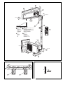
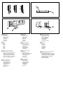
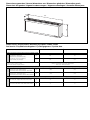
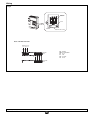
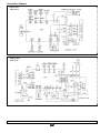
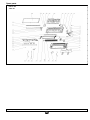
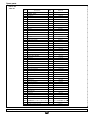
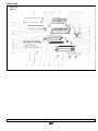
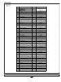
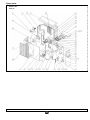
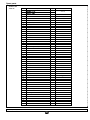
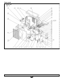
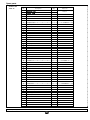
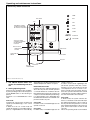
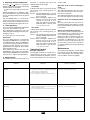
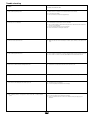
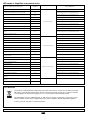
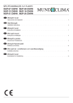
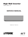
High Wall Inverter
YVHC 09 to 12
SERVICE MANUAL
YVHC 09 · YVHC 12
TI-YVHC-09-12GB 03-07
Fig. 1
2
> 15 cm
1
3
> 15 cm
>15 cm
> 70 cm
5
4
AUTO
CALEFACCIÓN
HEAT
CHAUD
AQUECIMENTO
RISCALDAMENTO
HEIZEN
VERWARMING
OPPVARMING
C
REFRIGERACIÓN / DESHUMIDIFICACIÓN
COOL / DRY
FROID / DÉSHUMIDIFICATION
REFRIGERAÇÃO / DESHUMIDIFICAÇÃO
RAFREDAMENTO / DEUMIDIFICAZIONE
KÜLEN / ENTFEUCHTEN
KOELING / ONTVOCHTIGING
AVKJØLIG / AVFUKTNING
SWING LIGHT AIR
6
h
MO
DE
SWING
P
FAN
SLEE
AIR
LIGHT
T-ON
+°C
-°C
T-OFF
MARCHA
ON
MARCHE
LIGAÇÃO
ACCESO
EIN
AAN
PÅ
AUTOMATICO
AUTO
AUTOMATIQUE
AUTOMÁTICO
AUTOMATICO
AUTOMATICBETRIEB
AUTOMATISCH BEDRIJF
AUTOMATISK
ON/OFF
> 15 cm
7
> 30 cm
> 50 cm
10
8
> 200 cm
9
Fig. 2
Fig. 3
5º
Fig. 4
Fig. 5
OK
Fig. 6
Fig. 7
7
11
9
5
1
Panel frontal
Front panel
Panneau frontal
Painel frontal
Pannello frontale
Frontblende
Frontpaneel
Frontpanel
5
Cinta vinilo
Vinyl tape
Ruban de vinyle
Fita de vinilo
Nastro vinilico
Klebeband
Vinyltape
Vinyltape
9
2
Filtros
Filters
Filtres
Filtros
Filtri
Filter
Filters
Filtre
6
Mando a distancia
Remote control unit
Télécommande
Comando à distância
Telecomando
Fernbedienung
Afstandsbediening
Fjernkontroll
10 Salida aire
Air outlet
Sortie d'air
Saída de ar
Uscita d'aria
Luftaustritt
Luchtuitlaat
Luftutløp
3
Tapa de conexiones eléctricas
Wire connection cover plate
Couvercle de connexions électriques
Tampa de conexões eléctricas
Coperchio dei collegamenti elettrici
Abdeckung elektrische Anschlüsse
Deksel voor elektrische aansluitingen
Lokk over elektriske koblinger
7
Manguera de desagüe
Drain hose
Tuyau de drainage
Mangueira de desaguamento
Tubo scarico condensa
Kondensatablauf
Afvoerslang
Avløpsslange
8
4
Cable de alimentación
Power supply cable
Câblage d'alimentation
Cabo de alimentação
Cavo d'alimentazione
Speisakabel
Netspanningkabel
Mateleding
Líneas frigoríficas
Cooling lines
Lignes frigorifiques
Linhas frigoríficas
Tubazioni frigorifere
Kälteleitungen
Koelleidingen
Kjølelinjer
Cable de interconexión
Interconnecting cable
Câblage d'interconnexion
Cabo de interligação
Cavo di collegamento
Verbindungskabel
Aansluitkabel
Forbindelsesledninger
11 Salida lateral de líneas de refrigerante
Refrigerant line side outlet
Sortie latérale dans lignes de réfrigérant
Saída lateral das linhas de refrigerante
Uscita laterale per i tubi del refrigerante
Seitlicher Austritt der Kälteleitung
Zijuitgang koellijnen
Sideutløp av kjølelinjer
Dimensiones generales / General dimensions mm / Dimensions générales / Dimensões gerais
Dimensioni d'ingombro / Algemeine abmessungen / Algemene afmetingen / Generelle dimensjoner
YVKC09DS-AAA, YVKC12DS-AAA
0
15
290
1005
Datos físicos / Physical data / Données physiques / Dados físicos
Dati tecnisi / Physikalische Angaben / Fysieke gegevens / Fysiske data
YVKC09DS-AAA
Modelo / Model / Modèle / Modelo / Modello / Modell / Model / Modell
YVKC12DS-AAA
Caudal / Flow / Débit / Caudal / Portata / Durchsatz / Luchtdebiet / Strøm
(Velocidad alta) / (High speed)
(Grande vitesse) / (Velocidade elevada)
(Velocità alta) / (Hohe Geschwindigkeit)
(Hoge snelheid) / (Høy hastighet)
m3/h
450
500
m3/s
0,13
0,14
Control / Control / Contrôle / Controlo
Comando / Bedienung / Regeling / Kontroll
Infrarrojos / Infrared rays / Infrarouges / Infravermelhos
Infrarossi / Ir / Infrarood / Infrarød
Conexiones frigoríficas / Cooling connections / Liaisons frigorifiques / Ligações frigoríficas / Collegamenti frigoriferi / Kälteanschlïsse / Koelaansluitingen / Kjølekoblinger
Diametro mayor / Larger diameter / Diamètre le plus grand
Diâmetro maior / Tubo di diam. maggiore
Durchm. dickes Rohr / Grootste diameter / Største diam.
mm
9,52
(3/8")
12,7
(1/2")
Diametro menor / Smaller diameter / Diamètre le plus petit
Diâmetro menor / Tubo di diam. minore
Durchm. dünnes Rohr / Kleinste diameter / Minste diameter
mm
6,35
(1/4")
6,35
(1/4")
Peso aproximado / Approximate weight / Poids approximatif / Peso aproximado / Peso approssivativo / Ungefähres Gewicht / Gewicht (ong.) / Tilnærmet vekt
Neto / Nett / Net / Líquido / Netto / Netto / Netto / Netto
kg
11
11
Bruto / Gross / Brut / Bruto / Lordo / Brutto / Bruto / Brutoo
kg
13
13
Installation Instructions
Inspection
Upon reception, inspect the equipment and
notify both the carrier and the insurance
company, in writing, of any possible damage.
Environmental protection
Eliminate packing in accordance
with the regulations in force on environmental conservation.
Installation of indoor unit
Fasten the mounting plate to the wall.
Tighten screws slightly. Level the mounting
plate, and then tighten screws to a maximum (Fig. 2).
If the tubing goes through the back of the
unit, drill a 50 mm. diameter hole in the wall.
The outer side of this hole should be slightly
below the inner side (Figs. 3 and 7). Install
the through guide.
The refrigerant lines can be installed in different positions (Fig. 6).
Installation of the interconnecting tubing
and wiring, with the central mounting
plate located at the back of the chassis.
Hang the upper part of the unit over the
mounting panel and press forward. Fasten
the indoor unit to the mounting plate permanently.
Bend the tubing carefully, without flattening
or obstructing it.
Pass the tubing and cables of the unit
through the hole; and hand the upper part
of the indoor unit on the upper edge of the
mounting plate (see Fig. 2).
Make sure the unit is installed properly,
moving it first to the left and then to the
right.
Cable section
YVKC09DS
Sizes
Power supply
mm2
YVKC12DS
3 x 2,5
3 x 2,5
4 x 2,5
4 x 2,5
Condensed water drain
The drain pipe of the unit is flexible and
can be placed in different positions. The
drain line should include an elbow (Ushaped) (Fig. 4). Connect a plastic condensed water drain pipe with a 12 mm. inner diameter.
The drain pipe should be fastened to the
cooling lines with vinyl tape (see Fig. 6).
Typical installation (Fig. 1)
Interconnection
(ind./out.)
Fuse (K Curve)
A
10
Prior to final approval of the
installation
Check:
This illustration shows, in general, a typical
installation of this equipment.
After carrying out a drain test, apply vinyl
tape, ref. 3, joining all tubing.
- The voltage is always between
198-254 V.
- The power supply cable section
is, at least, that recommended.
Wiring
- Condensed water drainage is
carried out correctly, and there
are no leaks in the water circuit.
1- Open the front panel.
2- Remove the wiring cover.
3- Locate the connecting cable from the
indoor unit, passing though the connecting hole.
4- Connect the blue power supply cable to
terminal “N(1)”, the brown cable to “2”
and the yellow-green cable to the ground
connection, as indicated in Fig. 8.
5- For heat pump models, connect the
power supply cables as indicated in Fig.
8, and fasten the cable to the casing.
6- Install the electrical connection protector.
7- Mount the front panel.
- Operating instructions have
been given to the user.
- Information has been given on
the need to clean the air filter
periodically.
- The guarantee card has been
filled out.
- Maintenance instructions have
been given, or a contract has
been made for periodical servicing.
ATTENTION
Your product is marked with this symbol. This means that at the end of its service life it should not be mixed
with other non-classified household waste. Therefore, disposal should be carried out in compliance with the
corresponding local and national regulations, in a correct and environment-friendly manner.
The dismantling of the air conditioning unit, as well as the processing of refrigerant, oil and other components, should be carried out by a qualified technician and in compliance with the applicable legislation.
Contact your local authorities for further information
GB
Wiring
Fig. 8
GROUND
TERMINAL
CLAMP
BLUE
BROWN
CONNECTING CABLE
Models YVKC09DS YVKC12DS
POWER SUPPLY
230/1 Ph/50 Hz
AZ
MA AM/V
N
L
N(1)
AZ
2
NG
N(1)
3
INDOOR
UNIT
MA AM/V
2
3
OUTDOOR
UNIT
All data subject to change without notice.
GB
MA: BROWN
AM/V: YELLOW/GREEN
AZ: BLUE
RJ: RED
AM: YELLOW
NG: BLACK
Connection Schema
Indoor units
YVKC 09-12
Outdoor units
YVJC 09-12
All data subject to change without notice.
GB
Spare parts
Indoor unit
YVKC 09
All data subject to change without notice.
GB
Spare parts
Indoor unit
YVKC 09
No
Qty
Description
Product Code
Part Code
YVKC 09
1
Wall Mounting Frame
1
2
Pipe Clamp
1
24242001
3
Rear Case
1
22202327
4
Motor FN20Y
1
15012068
5
Motor Clamp
1
22242034
6
Tube Sensor(20K)
1
390000595
7
Sensor insert
8
Receiver Board JKD
1
30046074
9
Wire Clip
1
42012415
10
Wire Clamp
1
71010103
11
Electric Box
1
20102186
43110233
1
01252001
42020063
12
Transformer 48X26G
1
13
Main PCB
1
30030120
14
Wire Slot
1
70482001
15
Terminal Board T4B3A
1
42011233
16
Electric Box Cover 1
1
20102187
17
Room Sensor(15K)
1
390000451
18
Front Case
19
Electric Box Cover 2
20
Filter
2
11122016
21
Front Panel Link
2
10582026
22
Front Panel Dowel
2
10562002
23
Front Panel Crank
2
10562001
24
Stepping Motor MP24GB
2
15212111
25
Front Panel
1
20002076
26
Front Panel Holder
1
01792006
27
Ornamental Bar
1
68012022
28
Pilot Lamp Frame
1
26112045
29
Pilot Lamp Panel
1
22432066
30
Button Panel
1
26112046
31
Evaporator Flashboard
1
010723101
32
Evaporator Support
1
24212028
1
1
20002119
20102188
33
Water Tray
1
20182032
34
Swing Link 1
1
10582024
35
Swing Link 2
1
10582025
36
Swing Louver
10
10512043
37
Guide Louver
1
10512042
38
Guide Louver Bearing
3
10542011
39
Connecting Cable
1
400205235
/
40
/
/
41
Drainage Pipe
1
052324111
42
Stepping Motor MP24GA
1
15212102
43
Evaporator Assy
1
01002221
44
Fan Bearing
1
76512210
45
Ring of Bearing
1
76512203
46
Cross Flow Fan
1
10352004
47
Remote Controller Y512F
1
30515002
48
Power Cord
1
49
Shield Box of Electric Box Assy
1
01592024
50
Shield Box of Electric Box Assy
1
01592032
All data subject to change without notice.
GB
40022011
Spare parts
Indoor unit
YVKC 12
All data subject to change without notice.
GB
Spare parts
Indoor unit
YVKC 12
No
Qty
Description
Exploded View
Part Code
YVKC 12
Product Code
1
Wall Mounting Frame
1
01252001
2
Pipe Clamp
1
24242001
3
Rear Case
1
22202327
4
Motor FN20Y
1
15012068
5
Motor Clamp
1
22242034
6
Tube Sensor(20K)
1
390000595
7
Sensor insert
1
42020063
8
Receiver Board JKD
1
30046074
9
Wire Clip
1
42012415
10
Wire Clamp
1
71010103
11
Electric Box
1
20102186
12
Transformer 48X26G
1
43110233
13
Main PCB
1
30039131
14
Wire Slot
1
70482001
15
Terminal Board T4B3A
1
42011233
16
Electric Box Cover 1
1
20102187
17
Room Sensor(15K)
1
390000451
18
Front Case
1
19
Electric Box Cover 2
20
Filter
2
11122016
21
Front Panel Link
2
10582026
22
Front Panel Dowel
2
10562002
23
Front Panel Crank
2
10562001
24
Stepping Motor MP24GB
2
15212111
25
Front Panel
1
20002076
26
Front Panel Holder
1
01792006
27
Ornamental Bar
1
68012022
28
Pilot Lamp Frame
1
26112045
29
Pilot Lamp Panel
1
22432066
30
Button Panel
1
26112046
31
Evaporator Flashboard
1
010723101
1
20002119
20102188
32
Evaporator Support
33
Water Tray
1
1
20182032
24212028
34
Swing Link 1
1
10582024
35
Swing Link 2
1
10582025
36
Swing Louver
10
10512043
37
Guide Louver
1
10512042
38
Guide Louver Bearing
3
10542011
39
Connecting Cable
1
40020538
/
40
41
Drainage Pipe
/
/
1
052324111
42
Stepping Motor MP24GA
1
15212102
43
Evaporator Assy
1
01002187
44
Fan Bearing
1
76512210
45
Ring of Bearing
1
76512203
46
Cross Flow Fan
1
10352004
47
Remote Controller Y512F
1
30515002
48
Power Cord
49
Shield Box of Electric Box Assy
1
01592024
50
Shield Box of Electric Box Assy
1
01592032
1
All data subject to change without notice.
GB
400204643
Spare parts
Outdoor unit
YVJC 09
All data subject to change without notice.
GB
Spare parts
Outdoor unit
YVJC 09
No
Qty
Description
Exploded View
Part Code
YVJC 09
Product Code
1
Front Panel
1
01533005
2
Clap Board
1
01233381
3
Reactor Box C
1
4
Reactor (L004)
1
5
Drainage Connecter
1
06123401
6
Reactor Support
1
01213429
7
Overload Protector
1
8
Compressor EU1011DV
01413504
1
43130165
00180039
00100125
9
Compressor Gasket
3
76710238
10
Bolt
3
70212014
11
Nut
3
70310014
12
Valve Support
1
01713041
13
Right Side Plate
1
01303048
07100005
14
Valve 3/8"
1
15
Valve 1/4"
1
07100003
16
Capillary Assy
1
03103018
17
4-Way Valve
1
430004022
18
4-way Rever-sing Valve Component
1
03023671
19
Big Handle
1
26233433
20
4-way Valve Coil
1
43000400
21
Wire Clap
1
71010103
22
Insulation Piece D
1
70410525
23
Terminal Board A
24
Capacitor (CBB61 2.5uF/450V(VDE) )
25
Electric Box 2
1
1
42011113
33010026
1
01413051
26
Capacitor (2200uF±20%/400V )
27
Capacitor (CBB60A 16uF/400V±10%)
28
Capacitor (100uF/400V±10% )
29
Electric Box A
1
20103501
30
PCB W923HAA
1
30039243
31
RoomTemperature Sensor 15K
1
1
33010803
33010054
1
1
33310054
3900012123
32
Tube Temperature Sensor 20K
1
39000071
33
Exhaust Gas Temperature Sensor 50K
1
39000016
34
Electric Box Cover
35
Power Module
1
32210096
36
Recti?er S15VB60
2
46010601
37
Sensor Insert
1
42020063
38
Radiator
1
49010212
39
Rear Grill
1
01473030
40
Condenser Assy
1
01103532
41
Top Cover
1
01253443
42
Motor Support
1
01703020
43130169
1
01413048
43
Reactor (L16.5mH/10A/14/650)
1
44
Reactor Box 1
1
01413035
45
Motor FW30K
1
15013067
46
Axial Flow Fan
1
10333414
47
Nut
1
70310131
48
Front Grill
1
22413431
All data subject to change without notice.
GB
Spare parts
Outdoor unit
YVJC 12
All data subject to change without notice.
GB
Spare parts
Outdoor unit
YVJC 12
No
Qty
Description
Exploded View
Part Code
YVJC 12
Product Code
1
Front Panel
2
Clap Board
3
Reactor Box C
1
01413504
4
Reactor (L004)
1
43130165
5
Drainage Connecter
1
06123401
6
Reactor Support
1
01213429
7
Overload Protector
1
00180039
8
Compressor EU1011DV
9
Compressor Gasket
3
76710238
10
Bolt
3
70212014
1
1
1
01533005
01233381
00100125
11
Nut
3
70310014
12
Valve Support
1
01713041
13
Right Side Plate
1
01303048
14
Valve 1/2"
1
07100006
15
Valve 1/4"
1
07100003
16
Capillary Assy
1
03103191
17
4-Way Valve
1
430004032
18
4-way Rever-sing Valve Component
1
03023234
19
Big Handle
1
26233433
20
4-way Valve Coil
1
430004002
21
Wire Clap
1
71010102
22
Insulation Piece D
1
70410525
23
Terminal Board A
24
Capacitor (CBB61 2.5uF/450V(VDE) )
25
1
1
42011113
33010026
Electric Box 2
1
01413051
26
Capacitor (2200uF±20%/400V )
1
33010803
27
Capacitor (CBB60A 20uF/400V±10%)
1
28
Capacitor (100uF/400V±10% )
1
29
Electric Box A
1
20103501
30
PCB W923HB
1
30039244
31
RoomTemperature Sensor 15K
1
33010057
33310054
3900012123
32
Tube Temperature Sensor 20K
1
39000071
33
Exhaust Gas Temperature Sensor 50K
1
39000016
34
Electric Box Cover
35
Power Module
1
32210093
36
Recti?er S25VB60
2
46010602
37
Sensor Insert
1
42020063
38
Radiator
1
49010212
01473030
1
01413048
39
Rear Grill
1
40
Condenser Assy
1
01103587
41
Top Cover
1
01253443
42
Motor Support
1
01703391
43
Reactor (L16.5mH/10A/14/650)
1
43130169
44
Reactor Box B
1
01413503
15013067
45
Motor FW30K
1
46
Axial Flow Fan
1
10333413
47
Nut
1
70310131
48
Front Grill
1
22413431
All data subject to change without notice.
GB
Operating and maintenance instructions
Infrared ray remote control unit
COOL
FAN SPEED
DRY
LCD
FAN
HEAT
HORIZONTAL SWING:
AUTOMATIC ROTATION
OF VERTICAL LOUVERS
FAN
AUTOFAN
AUTO
AUTO
OPER
SLEEP
°C
AIR
RE-BACTERIA
PURIF
AUTO
HUMID
HR.
AUTO FAN
FAN SPEED
TIMER ON/OFF
VERTICAL SWING:
AUTOMATIC ROTATION
OF HORIZONTAL
LOUVERS
AIR
DISPLAY LIGHT
RE-BACTERIA
LIGHT
NOT IN USE
TEMPERATURE
SETTING
TIMER
SELECCIÓN DE
MODO
HUMID
MODE
PURIF
SLEEP
ON/OFF
SLEEP MODE
ON / OFF
ON / OFF
PROGRAMMER
Note: Use alkaline AAA batteries only.
1. The ON/OFF button allows turning the air conditioning unit on or
off.
2. Setting operating mode
There are five operating modes available:
System operating mode can be set by pressing the MODE button, in the following sequence:
Automatic - Cool - Dehumidification - Vent Heat.
Vent mode
In FAN mode, only the fan is operative. Fan
speeds (low-medium-high) + auto can be
selected.
If AUTO is set in cool or heat mode, fan
speed will change in low-medium-high sequence, or high-medium-low automatically,
depending upon the differential between the
ambient temperature and the set points.
Dehumidification mode
In DRY mode, if the ambient temperature is
above the set point, the unit will operate in
cool mode with the fan on AUTO. If the ambient temperature is below this set point, the
compressor and fan ON/OFF periods will go
to a fixed repetition cycle, depending upon
the differential between the ambient temperature and the set point.
Cool mode
In COOL mode, low-medium-high-auto fan
speeds can be set.
Heat mode
In HEAT mode, low-medium-high-auto fan
GB
speeds can be set.
In order to avoid cold air originating in the
unit in heat operation, when the coil temperature is too low, the fan will stop. As the
coil temperature rises as a result of compressor operation, the fan restarts. This feature is also operative when the unit is turned
on, delaying fan operation until the temperature has reached the selected value.
Auto mode
In AUTO mode, the system switches between cool and heat modes automatically if
the ambient temperature is above or below
the set point. The unit operates in cool mode
if the ambient temperature is above the set
point, and in heat mode if it is below said
set point.
This is the operating mode recommended.
3. Adjusting ambient temperature
Press the
or
buttons to change the
ambient temperature set point. This should
remain between 16 and 30°C.
- To select fan speed and air louver position.
Speeds available are Low - Medium - High.
Press the FAN button to achieve the desired
air flow. The FAN symbol shows the speed
selected.
Use the SWING button to control the air
louvers. If pressed once, the louvers are stationary; if pressed a second time, the louvers
sweep to distribute air throughout the room.
4. Timer operations
The control unit is equipped with a timer that
sets the on and off times of the unit.
The configurations stored in the control unit
will be the predominating parameters upon
turning the unit on.
To use the timer, proceed as follows:
On/off timer
The on/off timing function is achieved by
pressing the TIMER button. To start the unit
at a determined time, press the TIMER button in half hour intervals until the on time is
achieved. The unit will start once the programmed time has elapsed, which will be
memorised by the unit.
In the same way, to turn the unit off at a determined time, carry out the same operation
by pressing the TIMER button as many times
as necessary to achieve the required time.
5. Sleep function
and Heat, is a program that controls the
ambient temperature at night.
Cool mode
In Sleep mode and cool operation, the unit
will operate in the following phase sequence: 1-2.
Phase 1: The unit will operate in cool mode
until the ambient temperature set
point is reached.
Phase 2: After reaching the ambient temperature set point, the unit will
operate in cool mode so as to
keep the ambient temperature
within the limits of the set point,
+1 to +2°C for 1 hour.
Heat mode
In Sleep mode and heat operation, the unit
will operate in the following phase sequence: 1-2.
Phase 1: The unit will operate in heat mode
until the ambient temperature set
point is reached.
Phase 2: After reaching the ambient temperature set point, the unit will
operate in heat mode so as to
keep the ambient temperature
within the limits of the set point,
-1 to -2°C for 1 hour.
of any trouble.
Operation of the system in Emergency
mode
Cool System
The ambient temperature set point is set to
20°C. The unit operates in the cool mode.
Heat and Cool System
The ambient temperature set point is set to
25°C. The unit operates in automatic mode.
Automatic reset and antifreeze protection
After any power failure, the unit resets automatically (when power supply is re-established), remaining in the same mode as prior
to the failure.
Defrost and overheating protection
This feature is used to avoid freezing of the
evaporating unit in cool or dry mode, as well
as to avoid overheating in heat mode.
When in the defrost (antifreeze) and overheating protection cycle, the compressor is
inoperative, its LED flashes in cycles and
the air louver stops in fully open position. At
the end of this cycle, the louver operates in
accordance with the previously programmed
parameters.
Operating Control
Maintenance
Emergency operation
The emergency switch is located in the receiving panel on the front of the unit. This
switch is used when the batteries of the remote control unit have run out, or in the case
These units are designed to operate during
long periods of time with minimum maintenance. Nevertheless, the following operations should be carried out regularly.
The Sleep mode, which can be used in Cool
Component
Maintenance
Frequency recommended
Dust filter:
1. Clean with a vacuum cleaner or tap lightly and wash with lukewarm water (40°C) and mild detergent.
2. Rinse and dry before reinstalling on unit.
3. Do not use gasoline, alcohol or other chemical products.
Every month, or more frequently if necessary.
Unit casing:
1. Remove dust from front panel with a soft rag or a rag moistened in a mild soapy solution.
2. Do not use gasoline, alcohol or other chemical products.
Every month, or more frequently if necessary.
Drain tray and pipe:
1. Clean and make sure there are no obstructions.
Every season prior to start-up.
GB
Trouble shooting
Problem
Possible cause and correction
A. Air conditioning unit inoperative.
1. Make sure fuse is not blown out or main switch has not been activated.
2. Is main switch set to OFF?
3. Has any mistake been made when programming?
B. Unit does not cool sufficiently.
1. Is the filter dirty? See instructions on how to clean filter.
2. The room was probably too warm when turning the unit on: Wait until the unit has had time to
lower the room temperature.
3. Has the adequate temperature been programmed?
4. Are the unit air intake or outlet grids obstructed?
C. There is a bad odour in the room.
1. Make sure said odour is not from dampness of walls, carpets, furniture or other fabrics in the
room.
D. Air conditioning unit makes noise.
1. A noise similar to running water: Caused by refrigerant liquid going through refrigerant circuit.
2. A noise similar to a shower: Caused by dehumidification water treated inside the unit.
E. Seems as if condensed water is flowing from the unit.
1. Condensation is produced when the unit cools the air in the room.
F. Air conditioning unit inoperative 3 minutes after reset.
1. Due to a system protecting device. Wait 3 minutes for operation to start again.
G. The remote control display becomes weak or goes off.
1. The batteries may need changing.
2. Do not invert polarity of the batteries when changing.
H. Air conditioning unit does not respond to remote control unit, or to direct manual
control.
1. The batteries may need changing.
2. Do not invert polarity of the batteries when changing.
3. Contact your authorized Service Centre to have them check the power supply of your
installation.
GB
LED codes in High Wall and cassette units
Failures description or protection behavier
Error code
on display
Indoor LED Behavier
HP Protection.
E1
The LED extinguishs for 3 seconds then flicker 1 times.
When inner tube temperature is low, the preset program will cut
off compressor, meanwhile the inner motor won’t stop.
E2
The LED extinguishs for 3 seconds then flicker 2 times.
System low pressure protection Lp/Bp protection.
E3
The LED extinguishs for 3 seconds then flicker 3 times.
Compressor discharge protection.
E4
The LED extinguishs for 3 seconds then flicker 4 times.
Overcurrent protection in low-voltage situation.
E5
Communication failure.
E6
Mode collision.
E7
The LED extinguishs for 3 seconds then flicker 7 times.
Anti-high-temperature protection.
E8
The LED extinguishs for 3 seconds then flicker 8 times.
Anti-cooling protection (Heating mode, start-up).
E9
The LED extinguishs for 3 seconds then flicker 9 times.
Reduce running frequency when the AC voltage falls down (Inverter).
E0
The LED extinguishs for 3 seconds then flicker 10 times.
No response from indoor motor.
H6
The LED extinguishs for 3 seconds then flicker 11 times.
Indoor ambient sensor short-circuit or open-circuit.
F1
The LED extinguishs for 3 seconds then flicker 1 times.
Indoor tube sensor short-circuit or open-circuit.
F2
The LED extinguishs for 3 seconds then flicker 2 times.
Outdoor ambient sensor short-circuit or open-circuit.
F3
The LED extinguishs for 3 seconds then flicker 3 times.
Outdoor tube sensor short-circuit or open-circuit.
F4
The LED extinguishs for 3 seconds then flicker 4 times.
Outdoor ambient sensor short-circuit or open-circuit.
F5
Reduce running frequency to protect overload in cooling mode.
F6
The LED extinguishs for 3 seconds then flicker 6 times.
Oil-return problem.
F7
The LED extinguishs for 3 seconds then flicker 7 times.
Reduce running frequency in overcurrent condition (inverter).
F8
The LED extinguishs for 3 seconds then flicker 8 times.
Reduce running frequency when discharge temperature is
overhigh (Inverter).
F9
The LED extinguishs for 3 seconds then flicker 9 times.
Defrosting problem.
H1
The LED extinguishs for 3 seconds then flicker 1 times.
Electrostatic dusting protection.
H2
The LED extinguishs for 3 seconds then flicker 2 times.
Compressor Overload protection.
H3
The LED extinguishs for 3 seconds then flicker 3 times.
System abnormally.
H4
The LED extinguishs for 3 seconds then flicker 4 times.
Module protection.
H5
Synchronous failure.
H7
The LED extinguishs for 3 seconds then flicker 7 times.
Water is full.
H8
The LED extinguishs for 3 seconds then flicker 8 times.
Electric-heating tube malfunction.
H9
The LED extinguishs for 3 seconds then flicker 9 times.
Reduce running frequency anti-high-temperature in heating mode
(Inverter).
H0
The LED extinguishs for 3 seconds then flicker 10 times.
Reduce running frequency when tube temperature is overhigh
(Inverter).
FA
Reduce the running frequency for Anti-icing (Inverter).
FH
The LED extinguishs for 3 seconds then flicker 5 times.
Running LED indicator.
Cooling mode LED indicator.
Heating mode LED indicator.
The LED extinguishs for 3 seconds then flicker 6 times.
The LED extinguishs for 3 seconds then flicker 5 times.
The LED extinguishs for 3 seconds then flicker 5 times.
ATTENTION
Your product is marked with this symbol. This means that at the end of its service life it should not be mixed
with other non-classified household waste. Therefore, disposal should be carried out in compliance with the
corresponding local and national regulations, in a correct and environment-friendly manner.
The dismantling of the air conditioning unit, as well as the processing of refrigerant, oil and other components, should be carried out by a qualified technician and in compliance with the applicable legislation.
Contact your local authorities for further information
All data subject to change without notice.
GB
DECLARACION CE DE CONFORMIDAD SOBRE MAQUINAS
FABRICANTE:
CLIMA ROCA YORK, S.L.
DIRECCIÓN:
Paseo Espronceda, 278, 08204 SABADELL
La máquina corresponde a las exigencias básicas de la Directiva de la CE sobre máquinas (Directiva "CE" 89/392/CEE), incluidas las modificaciones
de la misma y la correspondiente transposición a la ley nacional.
APLICACIÓN DE LA MÁQUINA:
TIPO:
AIRE ACONDICIONADO/REFRIGERACION
YVKC09DS-AAA, YVKC12DS-AAA
............................................................................
DIRECTIVAS DE LA CE APLICADAS:
89/392/EEC, 89/336/EEC, 73/23/EEC
NORMAS ARMONIZADAS APLICADAS:
EN292-1, EN292-2, EN-60335-1, EN60335-2-40, EN55104-1,
EN55104-2, EN61000-3-2, EN61000-3-3
NORMAS INTERNACIONALES Y
ESPECIFICACIONES TÉCNICAS APLICADAS:
EN ISO 9001, (Pr EN378)
Sabadell, (España)
LUGAR:
FIRMA:
ROMÁN LARRODA
JEFE CONTROL DE CALIDAD
DECLARATION OF COMPLIANCE ON MACHINERY
MANUFACTURER: CLIMA ROCA YORK, S.L.
ADDRESS:
Paseo Espronceda, 278, 08.204 SABADELL
This machine complies with the basic demands of the EC Standards on machinery (Standard "EC" 89/392/CEE), including any modification of same.
APPLICATION OF THE MACHINE:
TYPE: .
AIR CONDITIONER/COOLING
YVKC09DS-AAA, YVKC12DS-AAA
EC STANDARDS APPLIED:
MATCHING STANDARDS APPLIED:
INTERNATIONAL STANDARDS AND TECHNICAL SPECIFICATIONS
APPLIED :
PLACE:
Sabadell, (España)
89/392/EEC, 89/336/EEC, 73/23/EEC
EN292-1, EN292-2, EN-60335-1, EN60335-2-40, EN55104-1,
EN55104-2, EN61000-3-2, EN61000-3-3
EN ISO 9001, (Pr EN378)
SIGNATURES:
ROMÁN LARRODA
QUALITY CONTROL MANAGER
23
www.johnsoncontrols.com
TI-YVHC-09-12GB 03-07