1
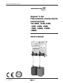
Oxiperm 164D 5-2000 g Service en
Oxiperm® C 164
Fully automatic chlorine dioxide
processing plant
164-005D, -010D,-030D,
-120D, -220D, -350D,
-700D, -1000D, -1500D,
-2000D
Service manual
15.710134-V3.0
1
Oxiperm 164D 5-2000 g Service en
Imprint
Oxiperm® C 164
Fully automatic chlorine dioxide
processing plant
164-005D,-010D,-030D,-120D,-220D,-350D,-700D,-1000D,-1500D,-2000D
Service manual
Version 3.0
Issued by:
ALLDOS Eichler GmbH
Reetzstraße 85 • 76327 Pfinztal (Söllingen)
Postfach 1160 • 76317 Pfinztal Germany
Tel. ++49 (0) 72 40 61-0 / Fax. ++49 (0) 72 40 61-177
E-Mail: [email protected]
Internet: http://www.alldos.com
© 2006 by ALLDOS Eichler GmbH
Subject to change without notice.
2
V3.0
Oxiperm 164D 5-2000 g Service en
Installation data
NOTE
Please fill in this form following commissioning. It will
help you and your ALLDOS servicing partner to adjust
the unit during subsequent corrections.
Owner:
ALLDOS customer No.:
Contract No.:
Order No. of unit:
Serial No. of unit:
Put into service on:
Location of unit:
Used for:
Installation diagram
15.710134-V3.0
3
Oxiperm 164D 5-2000 g Service en
Contents
Imprint ................................................................................................................ 2
Installation data ................................................................................................. 3
Installation diagram .......................................................................................... 3
1
General ..................................................................................................... 5
1.1
2
3
4
5
4
Spare parts set ........................................................................................... 5
Preparing the installation for maintenance .......................................... 6
2.1
Systems with M208 dosing pumps and a calibration system ..................... 6
2.2
Systems with M221 dosing pumps ............................................................. 7
Tests every 6 months ............................................................................. 8
3.1
Dosing tubes for HCl and NaClO2 .............................................................. 8
3.2
Checking the solenoid valves ..................................................................... 8
3.3
Checking the foot valves and float switch of the suction lines .................... 9
3.4
Check information signs ........................................................................... 10
3.5
Checking the dosing flow of the pumps for HCl and NaClO2 ................... 10
3.6
Relay connection for control system ......................................................... 11
Maintenance and tests every 12 months ........................................... 12
4.1
Tests
4.1.1
4.1.2
4.1.3
4.1.4
......................................................................................................... 12
Float switches and foot valves ....................................................... 12
Solenoid valve or circulating pump ................................................ 13
Dosing tubes and pipe lines .......................................................... 14
Relay connection for control system .............................................. 14
4.2
Maintenance ............................................................................................. 15
4.2.1 Reactor valves ............................................................................... 15
4.2.2 Ball check in the bypass line ......................................................... 16
4.2.3 Dosing pump for HCl and NaClO2 ................................................ 17
4.2.4 Suction injection (optional) for enclosure exhausting .................... 20
4.2.5 Dosing controller ........................................................................... 21
Tests every 24 months ......................................................................... 22
5.1
5.2
Oxiperm (Standard version) ...................................................................... 22
Oxiperm with internal bypass pump ......................................................... 22
5.3
Oxiperm with external bypass pump ........................................................ 22
5.4
Oxiperm for batch operation ..................................................................... 23
5.5
Suction lines ............................................................................................. 23
5.6
Option enclosure exhausting .................................................................... 23
6
Tests every 5 years ............................................................................... 24
7
Start-up after maintenance .................................................................. 25
7.1
Systems with M208 dosing pumps and a calibration system ................... 25
7.2
Systems with M221 dosing pumps ........................................................... 26
V3.0
Oxiperm 164D 5-2000 g Service en
1
General
NOTE
In accordance with the regulations for the prevention
of accidents GUV 8.15 and VGB 65 § 19 (2), the safety
of the chlorine dioxide systems must be checked by an
expert on a regular basis, at least once a year and
before each start-up.
These checks can be carried out by the service centre
within the framework of a 6 month or annual
maintenance check.
!
WARNING!
Before any maintenance work is carried out, i.e. if parts
and gaskets are replaced, the whole installation must
be flushed with water.
When maintenance work is carried out, any remains of
chemicals must be removed.
When working with acids or lyes, ensure that the
necessary protective clothing is worn.
Maintenance and repair work may only be carried out
by authorised qualified personnel.
1.1
Spare parts set
Each spare parts set includes the following parts:
15.710134-V3.0
●
Spare parts sets for the dosing pumps (diaphragm, valves, O-rings)
●
Flat gaskets for connection of solenoid valve or flow limiter
●
O-rings for: Bypass line DN20, impeller counter, circulating pump
●
Float bodies and O-rings for dosing controller
●
Valve unit for the reactor (3 valves for each)
●
Ball check DN20 for the bypass line
5
Oxiperm 164D 5-2000 g Service en
2
Preparing the installation for maintenance
For maintenance work which involves replacing components, the dosing pumps for
HCl and NaClO2 and the reactor must be flushed with demineralised water and the
bypass line with process water, in order to avoid direct contact with chemical
residues. For dosing pumps with a calibration system (M208), ensure that the
chemicals in the pre-lifting chamber are dosed first.
2.1
Systems with M208 dosing pumps and a calibration system
For dosing pumps M208 with a calibration system, ensure that the pre-lifting
chamber is emptied first.
●
Deactivate the installation via the display.
●
Remove the suction lines from the chemical containers and place separately
in an empty container.
●
Push the float switches of the suction lines upwards, in order to not produce
any error messages.
●
Acknowledge any error messages (pre-empty signals and empty signals)
for suction lines, which are caused by the float switches.
●
Switch to manual mode on the display
●
Set installation capacity to 100%
●
Activate installation
●
Set stroke setting for dosing pumps to 100%
●
Remove cover from pre-lifting chambers
The chemicals can now be dosed from the calibration system. The installation
continues to run until no more liquid is left in the pre-lifting chamber.
●
Deactivate installation
●
Place suction lines in a container that has been filled with demineralised
water,
or fill the empty container with demineralised water.
NOTE
Push float switches of the suction lines upwards, in
order to not produce any error messages and, if
necessary, acknowledge any error messages
●
Switch to service mode on the display
●
Switch to start-up mode
●
Activate start-up mode
●
Set stroke setting for dosing pumps to 100%
The dosing pumps and reactor can now be flushed with demineralised water.
NOTE
If the pre-lifting chamber is emptied so that the dosing
head has air in it, and thereby produces a dosing
controller error message, then the start-up operation
must be stopped in order to deaerate the suction lines
and dosing heads. Once this has been done, the startup operation can be resumed.
Once the start-up operation has finished, the bypass line then has to be flushed with
water.
6
●
Switch to deaeration mode on the display
●
Switch bypass on and flush for approximately 3-5 minutes
●
Switch bypass off
V3.0
Oxiperm 164D 5-2000 g Service en
2.2
Systems with M221 dosing pumps
For dosing pumps M221, there is no pre-lifting chamber, which has to be emptied
first.
●
Deactivate installation via display.
●
Remove suction lines from the chemical containers and place separately
in a container that has been filled with demineralised water.
●
Push float switches of the suction lines upwards, in order to not produce any
error messages.
●
Error messages (pre-empty signals and empty signals) for suction lines,
which are caused by the float switches.
NOTE
Push float switches of the suction lines upwards, in
order to not produce any error messages and, if
necessary, acknowledge any error messages
●
Switch to service mode on the display
●
Switch to start-up mode
●
Activate start-up mode
●
Set stroke setting for dosing pumps to 100%
NOTE
If there is air in the suction line, this will produce a
dosing controller error message. Stop the start-up
operation and deaerate the suction lines and dosing
heads. Once this has been done, the start-up operation
can be resumed.
The dosing pumps and reactor can now be flushed with demineralised water. Once
the start-up operation has finished, the bypass line then has to be flushed with
water.
15.710134-V3.0
●
Switch to deaeration mode on the display
●
Switch bypass on and flush for approximately 3-5 minutes
●
Switch bypass off
7
Oxiperm 164D 5-2000 g Service en
3
Tests every 6 months
During these tests, the following functions or components are checked, and if
necessary cleaned or replaced.
3.1
Dosing tubes for HCl and NaClO2
Here, the dosing tubes between the dosing pump and reactor inlet are checked for
wear, brittleness or discolouration which can be caused by possible leaking reactor
valves. These are replaced if necessary.
Wear/Brittleness
●
Replace dosing tubes
Discolouration
●
Replace dosing tubes
●
Replace reactor valves
NOTE
If the hose connections should show signs of
discolouration, caused by possible leaking reactor
valves, then they must be replaced.
Spare hoses
(includes: 2x connection screws DN4 or DN8; 1.5m hose DN4 or DN8)
3.2
Order No.
553-1555
Dosing tube DN4 (Colour: red) for HCl
Order No.
553-1556
Dosing tube DN4 (Colour: blue) for NaClO2
Order No.
553-1557
Dosing tube DN8 (Colour: transparent) for HCl
or NaClO2
Checking the solenoid valves
Here, the function of existing solenoid valves is checked. (depending on option)
●
Solenoid valves of the bypass line
●
Solenoid valves for suction of housing
●
Solenoid valves for suction of batch container
NOTE
If a solenoid valve is faulty, it must be replaced.
Spare valves
8
45.10245-1/2
Solenoid valve 230V, 50Hz
45.10249-1/2
Solenoid valve 115V, 60Hz
V3.0
Oxiperm 164D 5-2000 g Service en
3.3
Checking the foot valves and float switch of the suction lines
Here, the foot valves are checked for contamination along with the operation of the
float switches.
5
4
3
2
1
●
Check the connection to the suction line
●
Check mesh bottom plate (pos.1), seat (pos.2) and balls (pos.3) for
contamination, replace if necessary
●
Check the operation of the float switch
Spare parts for suction line
15.710134-V3.0
Pos.
Part No.
Designation
Installation
1
10.4559-401
Union nut, grey PVC
164-005D to
164-2000D
2
10.7299-400
Valve seat, grey PVC
164-005D to
164-2000D
3
10.6564
Ball, ceramics
164-005D to
164-2000D
4
10.7372-436
Float switch, PP
164-005D to
164-2000D
5
10.2254-400
Weighting stone, KER 1101
164-005D to
164-2000D
9
Oxiperm 164D 5-2000 g Service en
3.4
Check information signs
Here, the legibility of all installation signs or labels is checked.
●
"Warning" label
●
"HCl" label on dosing pump
●
"NaClO2" label on dosing pump
NOTE
If the labels are illegible or damaged, they must be
replaced.
Label
3.5
Part No.
Designation
Installation
12.6029-300
"Warning" label
all
12.6028-410
"HCI" label
all
12.6028-400
"NaClO2" label
all
Checking the dosing flow of the pumps for HCl and NaClO2
Here, the dosing pumps are calibrated, in order to check the set dosing volume. If
these deviate from the specified settings, the dosing pumps must be reset and
redosed.
Settings, see table
System
ClO 2
generation
performance *
At 6 bar
back-pressure
Max. system
pressure
Consumption of
components *
Dilution water requirement for bypass system
Solenoid valve
2)
Bypass pump
3)
50 Hz
60 Hz 1)
HCl
NaClO2
(standard)
Internal/external
In batch mode
Min. 4)
Max. 5)
(g/h)
(l/h)
(bar)
(bar)
(l/h)
(l/h)
(l/h)
(l/h)
(l/h)
(l/h)
164-030D
30
421
10
10
0,7
0,7
420
420
6
14
164-120D
120
426
9
6
2,9
2,9
420
420
25
55
164-220D
220
430
7
7
5,2
5,2
420
420
45
100
164-350D
350
437
9
9
8,3
8,3
420
420
70
160
164-700D
700
933
9
9
16,5
16,5
900
900
140
320
164-1000D
1000
948
9
9
24
24
900
900
200
450
164-1500D
1500
970
9
9
35
35
900
900
300
680
164-2000D
2000
996
9
6
48
48
900
900
400
900
10
V3.0
Oxiperm 164D 5-2000 g Service en
3.6
Relay connection for control system
Here, all relay connections are checked. To check on the display, switch to service
mode/test mode/relay. The following relays can be checked:
15.710134-V3.0
●
Dosing pump NaClO2
●
Dosing pump HCl
●
Bypass line (solenoid valve, circulating pump)
●
Suction of housing (solenoid valve)
●
Electrically isolated output - Auto/Manual
●
Electrically isolated output - error messages
●
Electrically isolated output - pre-empty signals
●
Electrically isolated output - dry-run batch container
●
Suction of batch container (solenoid valve)
11
Oxiperm 164D 5-2000 g Service en
4
Maintenance and tests every 12 months
During these maintenance tests, the following components are checked, and if
necessary cleaned or replaced.
4.1
Tests
●
Float switches and foot valves
●
Solenoid valve or circulating pump of the bypass line
●
Hose connections and pipe lines
●
Relay connection for control system
4.1.1 Float switches and foot valves
5
4
3
2
1
12
●
Check the connection to the suction line
●
Check mesh bottom plate (pos.1), seat (pos.2) and balls (pos.3) for
contamination, replace if necessary
●
Check the operation of the float switch
V3.0
Oxiperm 164D 5-2000 g Service en
4.1.2 Solenoid valve or circulating pump
Here, the operation and tightness of the solenoid valve or circulating pump and flow
limiter are checked.
●
Switch to service mode/start-up mode on the display Bypass water
●
Switch bypass on, in order to check the operation of the solenoid valve or
circulating pump
.
●
The specified amount of water on the display must be within the set
tolerances.
●
Check the tightness of the solenoid valve or circulating pump, replace if
necessary
.
●
Check connection screws and O-rings (pos. 2) of the circulating pump,
replace O-rings if necessary
●
Check tightness of flow limiter, replace flat gaskets (pos. 1) if necessary
NOTE
●
15.710134-V3.0
Observe mounting position (flow direction)!
Switch bypass off
13
Oxiperm 164D 5-2000 g Service en
4.1.3 Dosing tubes and pipe lines
Here, the dosing tubes between the dosing pump and reactor inlet are checked for
wear, brittleness or discolouration which can be caused by possible leaking reactor
valves. These are replaced if necessary.
Wear/Brittleness
●
Replace dosing tubes
Discolouration
●
Replace dosing tubes
●
Replace reactor valves
NOTE
If the hose connections should show signs of
discolouration, caused by possible leaking reactor
valves, then they must be replaced.
●
Checking the return pipes of the dosing pumps
●
Check tightness of the bypass line, activate bypass in service mode, if
necessary .
Spare hoses
(includes: 2x connection screws DN4 or DN8; 1.5m hose DN4 or DN8)
Order No.
553-1555
Dosing tube DN4 (Colour: red) for HCl
Order No.
553-1556
Dosing tube DN4 (Colour: blue) for NaClO2
Order No.
553-1557
Dosing tube DN8 (Colour: transparent) for HCl
or NaClO2
4.1.4 Relay connection for control system
Here, all relay connections are checked. To check on the display, switch to service
mode/test mode/relay. The following relays can be checked:
14
●
Dosing pump NaClO2
●
Dosing pump HCl
●
Bypass line (solenoid valve, circulating pump)
●
Suction of housing (solenoid valve)
●
Electrically isolated output - Auto/Manual
●
Electrically isolated output - error messages
●
Electrically isolated output - pre-empty signals
●
Electrically isolated output - dry-run batch container
●
Suction of batch container (solenoid valve)
V3.0
Oxiperm 164D 5-2000 g Service en
4.2
Maintenance
●
Reactor valves
●
Ball check in the bypass line
●
Dosing pump for HCl and NaClO2
●
Suction injector (optional)
●
Dosing controller
4.2.1 Reactor valves
NOTE
During these maintenance tests, the reactor valves
must be fully replaced.
●
Close ball valve on the injection unit or close ball valve following installation
●
Open pipe line connections above the reactor and hose connections of the
dosing pumps
●
Replace reactor valves
●
Tighten pipe line connections above the reactor and hose connections of
the dosing pumps
Spare parts for the reactor (valves, 3x)
Part No.
Designation
Installation
553-640.1
for system backpressure, lower than
3 bar
164-005D to
164-010D
553-641.1
for system backpressure, higher than
3 bar
164-005D to
164-010D
553-640
for system backpressure, lower than
3 bar
164-030D to
164-220D
553-641
for system backpressure, higher than
3 bar
164-030D to
164-220D
553-642
for system backpressure, lower than
3 bar
164-350D to
164-2000D
553-643
for system backpressure, higher than
3 bar
164-350D to
164-2000D
NOTE
The reactor valves are not identical to the valves of the
dosing pumps!
Do not interchange valves!
10.7403-351
553-640
553-641
(12.6020-10)
(12.6020-11)
10.8093-331
10.8093-331
15.710134-V3.0
10.8090-331
10.8090-331
10.7402-351
10.7403-351
10.7402-351
553-642
553-643
(12.6020-20)
(12.6020-21)
10.7402-351
10.7402-351
10.7402-351
10.7402-351
15
Oxiperm 164D 5-2000 g Service en
4.2.2 Ball check in the bypass line
Here, the ball check is replaced in the bypass line.
●
Deactivate installation
●
Close ball valves before and after installation
●
Loosen screws (pos. 1) of the non-return valve
●
Replace non-return valve
NOTE
●
16
Observe mounting position (flow direction)!
Tighten screws (pos. 1)
V3.0
Oxiperm 164D 5-2000 g Service en
4.2.3 Dosing pump for HCl and NaClO2
Removing the diaphragm
●
Insert suction lines of the pumps into a water container and allow the
installation to run until the dosing heads of the pumps have been fully
flushed with water.
●
Loosen deaeration screws by 1 turn, until the deaeration lines are flushed
as well. Then switch the installation off.
●
Loosen the four dosing head screws
●
Remove the dosing head and unscrew the diaphragm in an anticlockwise
direction.
Assembly
●
Insert the intermediate ring in such a way that the relief hole faces
downwards.
●
Screw in diaphragm
●
Switch on pump briefly, until the diaphragm reaches the back dead
point.
●
Carefully fit the dosing head and gradually tighten the screws in a
diagonal sequence, so that the dosing head is not damaged
●
.
Deaerate the pump
Dosing pump M208
Here, the dosing pumps for HCl and NaClO2 are serviced. Those parts are replaced
which are on the spare parts set.
●
Deactivate the installation or dosing pumps
Spare parts for double head system 164-030/120D
Order No.
Spare parts for double head system 164-220DOrder No.
15.710134-V3.0
Pos.
Part No.
Designation
3
10.8090-331
SD valve DN4
4
10.8092-430
Deaeration cartridge
17
10.8077-302
Dosing diaphragm
20
52.183
O-ring, Viton
37
50.272
Oval head screw
73
52.337
O-ring, Viton
553-1486
553-1488
17
Oxiperm 164D 5-2000 g Service en
18
V3.0
Oxiperm 164D 5-2000 g Service en
Dosing pumps M221
Dosing pumps for 164-350D and 164-700D
8
1
3
2
Spare parts for dosing head M221
Order No.
553-520-3
Pos.
Part No.
Designation
Installation
1
10.5503-300
Dosing diaphragm, PTFE/NBR
164-350D and
164-700D
2
54.154-400
Profiled gasket, NBR
3
54.125
8
10.7400-321
Grooved ring, Perbunan
164-350D and
164-700D
164-350D and
164-700D
SD valve DN8
164-350D and
164-700D
Dosing pumps for 164-1000D
Spare parts for dosing head M221
Order No.
553-521-3
Pos.
Part No.
Designation
Installation
1
10.5940-300
Dosing diaphragm, PTFE/NBR
164-1000D
2
54.154-400
Profiled gasket, NBR
3
54.125
8
10.7400-321
Grooved ring, Perbunan
164-1000D
164-1000D
SD valve DN8
164-1000D
Dosing pumps for 164-1500D
Spare parts for dosing head M221
15.710134-V3.0
Order No.
553-522-3
Pos.
Part No.
Designation
Installation
1
10.6001-300
Dosing diaphragm, PTFE/NBR
164-1500D
2
54.154-400
Profiled gasket, NBR
3
54.125
8
10.7400-321
Grooved ring, Perbunan
SD valve DN8
164-1500D
164-1500D
164-1500D
19
Oxiperm 164D 5-2000 g Service en
Dosing pumps for 164-2000D
Spare parts for dosing head M221
Order No.
553-523-3
Pos.
Part No.
Designation
Installation
1
10.5898-300
Dosing diaphragm, PTFE/NBR
164-2000D
2
54.154-400
Profiled gasket, NBR
3
54.125
8
10.7400-321
164-2000D
Grooved ring, Perbunan
164-2000D
SD valve DN8
164-2000D
4.2.4 Suction injection (optional) for enclosure exhausting
In the case of water which has a high deposit content, deposits can change the
nozzle ratio of the injector in such a way that it causes a drop in performance during
suction. In this case the nozzle must be cleaned.
ATTENTION
Do not use sharp objects to clean the nozzles.
Diluted hydrochloride acid has proven to be the most
suitable cleaning agent.
Observe the regulations when using hydrochloric acid!
For each service, the operation and tightness of the suction injector must be
checked, replace the following parts if necessary:
Pos. 12, 15, 11, 8, 7, 6, 4, 21
21
4
6
7
8
11
12
NOTE
20
13
15
16
17
15
The following parts are not included on the spare parts
set!
V3.0
Oxiperm 164D 5-2000 g Service en
Pos.
Designation
Part No.
4
O-ring
52.125
6
PTFE piston
12.171-4
7
Seat
12.120-4
8
O-ring
52.139
11
Diaphragm
12.312-4
12
O-ring
52.141
13
Diffuser B, complete
12.591-42
164-030D,164-120D,
164-220D
Diffuser C, complete
12.591-43
164-350D,164-700D,
164-1000D,164-1500D,
164-2000D
15
O-ring (2x)
52.123-2
17
Nozzle B
12.584-42
164-030D, 164-120D,
164-220D
Nozzle C
12.584-43
164-350D, 164-700D,
164-1000D
164-1500D, 164-2000D
O-ring
52.164
21
Installation
4.2.5 Dosing controller
When the dosing controller is serviced, the float bodies are replaced and if
necessary also the O-rings of the connection.
●
Deactivate the installation
●
Loosen the screws on the dosing tubes
●
Unscrew the dosing controller (pos. 1) from the dosing pump
●
Unscrew the upper part (pos. 12)
●
Replace the float body (pos. 10)
NOTE
15.710134-V3.0
Observe mounting position!
●
Check O-rings, replace if necessary
●
Fit upper part back on
●
Fit dosing controller back onto the pump
●
Tighten dosing tubes again
21
Oxiperm 164D 5-2000 g Service en
5
Tests every 24 months
NOTE
5.1
For this test, we recommend replacing the following
components!
Oxiperm (Standard version)
Bypass line with solenoid valve + flow limiter
●
Replace the solenoid valve + flow limiter
●
Replace the impeller counter (flow meter)
Part No.
Installation
12.3532-405
Solenoid valve 230V
with flow limiter 7 l/min
164-005D to
164-350D
12.3532-406
Solenoid valve 115V
with flow limiter 7 l/min
164-005D to
164-350D
12.3532-403
Solenoid valve 230V
with flow limiter 15l/min
164-700D to
164-2000D
12.3532-404
Solenoid valve 115V
with flow limiter 15l/min
164-700D to
164-2000D
12.6010-1
5.2
Designation
Flow meter FHKU 100
all
Oxiperm with internal bypass pump
Bypass line with internal circulating pump + flow limiter
5.3
●
Replace the circulating pump + flow limiter
●
Replace the impeller counter (flow meter)
Part No.
Designation
Installation
12.6078-400
Bypass pump 230V, cpl.
164-005D to -2000D
53.650-005
Bypass pump 115V
164-005D to -2000D
12.6010-1
Flow meter FHKU 100
164-005D to -2000D
53.625-70
Flow limiter 7 l/min
164-005D to - 350D
53.625-150
Flow limiter 15 l/min
164-700D to -2000D
Oxiperm with external bypass pump
Bypass line with external rotary pump + flow limiter
22
●
Replace flow limiter
●
Replace the impeller counter (flow meter)
Part No.
Designation
Installation
12.6010-1
Flow meter FHKU 100
164-005D to 2000D
53.625-70
Flow limiter 7 l/min
164-005D to - 350D
53.625-150
Flow limiter 15 l/min
164-700D to -2000D
V3.0
Oxiperm 164D 5-2000 g Service en
5.4
Oxiperm for batch operation
Bypass line with solenoid valve + ball valve
5.5
●
Replace solenoid valve
●
Replace the impeller counter (flow meter)
●
Replace pressure retention valve
Part No.
Designation
Installation
12.6010-1
Flow meter FHKU 100
12.6010-2
Flow meter FHKU 40
164-350D
12.6010-3
Flow meter FHKU 56
164-700D
12.6010-4
Flow meter FHKU 25
164-220D
12.6010-5
Flow meter FHKU 20
164-120D
12.6010-6
Flow meter FHKU 15
164-030D
12.6010-7
Flow meter FHKU 10
164-005D/-010D
53.919-10
PVC solenoid valve 230V 50/60Hz
all
53.919-11
PVC solenoid valve 110V 50/60Hz
all
525-0567
Pressure retention valve DN8
164-030D to
164-220D
525-1113
Pressure retention valve DN20
164-350D to
164-2000D
164-1000D to
164-2000D
Suction lines
Here, the suction lines are checked.
5.6
●
Replace foot valve + ball
●
Check suction lines for brittleness, replace if necessary
Option enclosure exhausting
Here, the operation of the solenoid valve is checked.
NOTE
In the event of a faulty solenoid valve, it must be
replaced.
Spare valves
15.710134-V3.0
45.10245-1/2
Solenoid valve 230V, 50Hz
45.10249-1/2
Solenoid valve 115V, 60Hz
23
Oxiperm 164D 5-2000 g Service en
6
Tests every 5 years
NOTE
24
For this test, we recommend replacing the following
components!
●
Replace the dosing pump for HCl
●
Replace the dosing pump for NaClO2
V3.0
Oxiperm 164D 5-2000 g Service en
7
Start-up after maintenance
After each maintenance procedure, the following points or settings should be
checked:
7.1
●
System type and operating mode
●
Dosing flow of the pumps for HCl and NaClO2 (dosing flow, see
documentation, Settings), the dosing pumps must be calibrated, if necessary,
deaerate the dosing head
●
Operation of dosing controller, adjust if necessary
●
Volume of bypass water
●
Screws
●
Tightness of installation
Systems with M208 dosing pumps and a calibration system
For dosing pumps M208 with a calibration system, ensure that the water is emptied
out of the pre-lifting chamber.
●
Deactivate installation via display.
●
Remove suction lines from the water containers
●
Push float switches of the suction lines upwards, in order to not produce any
error messages.
●
Error messages (pre-empty signals and empty signals) for suction lines,
which are caused by the float switches.
●
Switch to manual mode on the display
●
Set installation capacity to 100%
●
Activate installation
●
Set stroke setting for dosing pumps to 100%
●
Remove cover from pre-lifting chambers
The water is now dosed from the calibration system. The installation continues to
run until no more liquid is left in the pre-lifting chamber.
●
Deactivate installation
●
Connect suction lines to the chemical containers
The settings listed in Section 3 are now checked.
15.710134-V3.0
●
System type and operating mode
●
In Service mode/Deaeration, deaerate both dosing pumps
●
Check operation of dosing controller, adjust if necessary
●
Check volume of bypass water
●
Calibrate dosing pumps (e.g manual mode, installation capacity 100%)
and set to the required dosing line
●
Activate installation and check the tightness of all screws
25
Oxiperm 164D 5-2000 g Service en
7.2
Systems with M221 dosing pumps
For dosing pumps M221, there is no pre-lifting chamber, which has to be emptied
first.
●
Deactivate installation via display.
●
Connect suction lines to the chemical containers
The settings listed in Section 3 are now checked.
26
●
System type and operating mode
●
In Service mode/Deaeration, deaerate both dosing pumps
●
Check operation of dosing controller, adjust if necessary
●
Check volume of bypass water
●
Calibrate dosing pumps (e.g manual mode, installation capacity 100%)
and set to the required dosing line
●
Activate installation and check the tightness of all screws
V3.0
Oxiperm 164D 5-2000 g Service en
15.710134-V3.0
27
Oxiperm 164D 5-2000 g Service en
28
V3.0