1
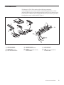
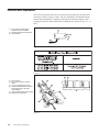
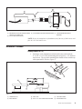
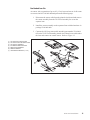
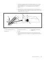
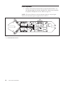
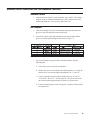
Installation & Service Manual
Frameworx Tel-E-Foul
July 2005 / 53-900676-000
Frameworx Tel-E-Foul Installation Manual
© July 2005 by the Brunswick Bowling & Billiards Corporation. All rights reserved.
Past Revisions: March 1998, April 1998, November 1998
Tel-E-Foul is a registered trademark of the Brunswick Bowling & Billiards Corporation.
Reorder Part No. 53-900676-000
Notice: If available, updates to this manual can be found on-line at www.brunswickbowling.com.
Confidential proprietary information. All information contained in this document is subject to change without notice.
Brunswick Bowling & Billiards Corporation
525 W. Laketon Avenue
Post Office Box 329
Muskegon, MI 49443-0329
U.S.A.
231-725-3300
2
Tel-E-Foul Installation
Table of Contents
Warranty and Service Policy ..................................................................... 5
Replacement Parts Under the Warranty ....................................................... 5
Brunswick Tel-E-Foul Standard Packaging ............................................... 6
General Description .................................................................................. 8
Parts Identification .................................................................................... 9
Electrical Power Requirements ................................................................ 10
Installation Procedure ............................................................................. 11
Subway Return (10-1/2") ..................................................................... 11
Non-Standard Lane Pair ...................................................................... 15
Brunswick Tel-E-Foul Reflector ........................................................... 16
Sensor Adjustment ............................................................................... 18
Brunswick Scorer Connections (AMF and Brunswick Pinsetters) ............ 19
Brunswick Pinsetter ............................................................................. 19
AMF Pinspotter .................................................................................. 19
Tel-E-Foul Installation
3
Intentionally Blank
4
Tel-E-Foul Installation
Warranty and Service Policy
If any defects in material or workmanship appear during the first three months
after installation, the defective part will be repaired or replaced, at Brunswick’s
option, with no charge to the Customer.
If any defects in material appear during the nine months following the initial three
month warranty period, the defective part will be repaired or replaced, at
Brunswick’s option, with no charge to the Customer for parts. The Customer
must assume all other costs in making the repair or replacement.
All service calls during the first three months of the warranty period, resulting
from the inability of the Customer’s mechanics to perform required adjustments
or maintenance, will be billed directly to the Customer.
Brunswick reserves the right to change the design of any product, but assumes no
responsibility to incorporate such design changes on products already sold.
The warranty applies only to new products installed by Brunswick and extends
only to the original purchaser. Repairs or replacements made by anyone not
approved by Brunswick void the warranty.
Under no circumstances shall the Seller or Manufacturer be liable for loss of
profits or other direct or indirect costs, expenses, losses, or damages arising out of
defects in or failure of parts.
Replacement Parts Under the Warranty
All service parts are F.O.B. the installation site both during and after the warranty
period. The price of parts includes delivery by standard means, such as United
Parcel Service (UPS). Any expense resulting from expedited delivery, such as air
freight, will be billed to the Customer.
During the one year period, parts which are faulty due to material or workmanship
will be replaced or repaired free of charge only if the old part is properly identified
and turned in for credit. Identify the defective part by attaching a tag containing
the part name and part number. Light bulbs are not covered by the warranty.
Service parts are ordered through the Brunswick Bowling and Billiards Corporation toll free number: 1-800-YES-BOWL or for international, 1-231-725-3300.
Refer to the “General Information” section of the Bowling Service Parts
Catalog for address and order information. When ordering service parts,
specify part numbers and descriptions to simplify handling. Use only Genuine
Brunswick Replacement Parts.
Tel-E-Foul Installation
5
Brunswick Tel-E-Foul Standard Packaging
1
L2-510001-101
1
Package Brunswick Tel-E-Foul Equipment (1 per ball return)
53-861068-000
1
53-600177-000
Assembly, Tel-E-Foul
1
53-860299-000
Package, Reflector Kit, Tele-E-Foul
1
2
53-860299-001
Bracket, Reflector Mounting, 1-1/4" Diameter
2
53-860299-002
Reflector, 1-1/4" Diameter
2
53-860299-003
Bracket, Reflector Mounting
2
53-860299-004
Screw, Self Tapping, #8 x 1-1/4"
2
53-860299-005
Screw, Pan Head, #6-32 x 5/16"
53-861071-000
4
2
1
53-861068-001
Screw, Self Tapping #8 x 1-1/4"
Wire Tie, Nylon, 6"
*53-860326-230
Transformer Kit, Tel-E-Foul, 230V
1
53-600180-230
Transformer, Tel-E-Foul, 230V 50 HZ
1
53-860326-001
Connector, IEC, Power
1
53-860326-002
Bracket, Mounting, Transformer
4
53-860326-003
Screw, Self Tapping, #8 x 3/4"
*53-860327-115
Transformer Kit, Tel-E-Foul, 115V
1
53-600180-115
Transformer, Tel-E-Foul, 115V 60 HZ
1
53-860327-001
Connector, IEC, Power
1
53-860326-002
Bracket, Mounting, Transformer
4
53-860327-003
Screw, Self Tapping, #8 x 3/4"
L2-510009-100
1
6
53-861071-001
L2-510010-115
1
1
Package, Hardware, Tel-E-Foul Mounting
L2-510010-230
1
1
Package, Tel-E-Foul
*53-860326-100
Transformer Kit, Tel-E-Foul, 100V
1
53-600180-100
Transformer, Tel-E-Foul, 100V 50 HZ
1
53-860326-001
Connector, IE C, Power
1
53-860326-002
Bracket, Mounting, Transformer
4
53-860326-003
Screw, Self Tapping, #8 x 3/4"
Tel-E-Foul Installation
1
**53-861069-000
Package, Remote Sensor Kit, (see Figure 12 page 10)
1
53-600177-002
Plate, Sensor Mounting
4
53-861069-001
Screw, Self Tapping, #6-32 x 1-1/4"
1
53-861069-002
Wire Harness, Remote Sensor, 120"
*NOTE: Transformer dependant upon country of installation site.
**NOTE: Used in non-standard lane installation only.
Tel-E-Foul Installation
7
General Description
The Brunswick Tel-E-Foul is a microprocessor based unit which operates on 12
volt AC power and uses an infrared signal for foul detection. The Tel-E-Foul unit
gives two signals to indicate a foul; a buzzer and a red light. The Tel-E-Foul also
provides a third signal for use at centers with automatic scorers.
The Tel-E-Foul microprocessor is designed to perform a functional test when the
unit is turned on. It will test the infrared signal for proper reflection strength, and
test for burned out foul indicator lights. If an error is detected during these tests,
the buzzer will be turned on for a short time and then the left-hand and right-hand
foul indicator lights will alternately turn off and on for a short time. If the infrared
signal is weak, approximately two signal strength indicator lights on, the buzzer
gives a short signal. If it is the left-hand lane, the sound will be constant and if it
is the right-hand lane, there will be a pulsing sound. If there is no infrared signal
there will be a long constant sound for the left-hand lane and a long pulsing sound
for the right-hand lane. After the buzzer alerts the mechanic, the lamp will
alternately turn off and on to indicate which lane has a Tel-E-Foul problem.
Shipped with the Tel-E-Foul package is a transformer that reduces a high voltage
supply furnished by the customer, to the 12VAC required to operate the Tel-EFoul assembly.
Prior to installation of the Tel-E-Foul the customer must provide appropriate
power according to the chart labeled Figure 3.
Replacement parts for the Brunswick Tel-E-Foul are shown in the Bowling
Service Parts Catalog (part number 28-201739-000)
8
Tel-E-Foul Installation
Parts Identification
The Brunswick Tel-E-Foul consists of the following components:
one mounting plate, two sensor assemblies with mounting platform, two foul
indicator light assemblies with mounting platform, one buzzer, one printed circuit
board, one two-conductor power supply cable and a four wire cable to provide a
foul signal to a scorer console. Refer to Figure 1.
Figure 1.
(1)
(4)
(7)
(10)
(13)
DIVISION HOUSING
OPTICAL SENSORS
REFLECTOR
12VAC POWER CABLE
FOUL INDICATOR LIGHTS
(2)
(5)
(8)
(11)
RETURN HOUSING
PRINTED CIRCUIT BOARD
BUZZER
RIGHT LANE (GREEN/YELLOW)
SCORER CABLE
(3)
(6)
(9)
(12)
TEL-E-FOUL UNIT
MAIN CHASSIS
LEDS
LEFT LANE (GRAY/ORANGE)
SCORER CABLE
Tel-E-Foul Installation
9
Electrical Power Requirements
The Tel-E-Foul power cables are to be provided and installed by the customer’s
electrician. Refer to Figures 2 and 3. On new installations, this should be done
after the lane foundation is completed. Junction box locations and power cable
routings for both new and modernization installations are shown in Figures 2, 3, 4
and 5.
(1) TEL-E-FOUL POWER CABLE
FURNISHED BY CUSTOMER
(2) INCOMING ELECTRICAL SERVICE
(3) JUNCTION BOX
Figure 2.
Figure 3.
(1) BALL RETURN
(2) 24" (610 mm) LONG PLYWOOD
SHELF
(3) 18" (457 mm) FROM FOUL LINE
(4) SUGGESTED METHOD OF WIRING
FOR SUBWAY BALL RETURN
JUNCTION BOX
(5) JUNCTION BOX AND POWER CORD
(6) SUBWAY BALL RETURN
Figure 4.
10
Tel-E-Foul Installation
Figure 5.
(1) BRUNSWICK SUPPLIED TRANSFORMER (2) CUSTOMER SUPPLIED POWER SOURCE (3)
AND IEC 320 CONNECTOR
(4) #8 X 3/4 HEX HEAD SCREW
TRANSFORMER MOUNTING
BRACKET
NOTE: Secure the transformer to foundation (out of the way of ball return) with
four #6 x 3/4" hex head screws.
Installation Procedure
Subway Return (10-1/2")
1.
On stringer or crib foundations notch the anchor strips and install the
9" x 2-3/4" x 3/4" Tel-E-Foul mounting plate using #14 x 1-1/2" flat head
wood screws. The top of the mounting plate should be flush with the top
of the approach fill. Refer to Figure 6.
Figure 6.
(1) APPROACH FILL
(4) BALL RETURN
(2) FOUL LINE
(5) #14 X 1-1/2" FLAT HEAD WOOD SCREW
(3)
(6)
ANCHOR STRIPS
MOUNTING PLATE
Tel-E-Foul Installation
11
2.
Connect the power cable to the Tel-E-Foul unit. Refer to Figure 7.
(1)
(2)
(3)
(4)
(5)
POWER CABLE
TEL-E-FOUL UNIT
BLACK
WHITE
RIGHT-LANE (YELLOW AND GREEN)
SCORER CABLE
(6) LEFT-HAND (ORANGE AND GRAY)
SCORER CABLE
Figure 7.
NOTE: Set jumpers for Brunswick or AMF scorers as shown in Figure 8.
IMPORTANT: If the AMF position is used on a Brunswick system, damage
may result to the automatic scorers.
(1) SET FOR BRUNSWICK SCORES
(2) SET FOR AMF SCORERS
Figure 8.
12
Tel-E-Foul Installation
3.
Position the Tel-E-Foul unit with the center of the optical head lenses
on the center of the foul line and the unit centered on the ball return.
Refer to Figure 9.
Figure 9.
(1) CENTER LINE OF SENSOR
(2) SENSOR
4.
(3)
FOUL LINE
Mark the mounting hole locations, set the units aside, and drill holes for
the mounting screws. Use two 1/4 x 2" lag screws, one in the mounting
plate and one in the approach fill. Replace the unit and mount in place.
Refer to Figure 10.
NOTE: On laminate lanes drill a 5/16" (7.93 mm) clearance hole through the
laminate before installing the 1/4" lag screws.
(1) 1/4 X 2" LAG SCREW
Figure 10.
Tel-E-Foul Installation
13
5.
Position the cover over the unit and trim the gutter and capping for a
smooth fit and a clear opening for the optical beam to the reflector.
Openings in the side of the cover should be centered on the optical
sensors. Mark the mounting hole locations using the cover as a template. Drill a 1/2" diameter hole in the approach and install a Tap-Loc
insert. Install a T-nut in the mounting plate. Install the cover using the
hardware shown in Figure 11.
NOTE: On laminate lanes drill a 1/2" clearance hole in the laminate before
drilling the hole for the Tap-Loc insert.
Figure 11.
(1)
(2)
(3)
(4)
(5)
SELF TAPPING SCREW, #8 X 1-1/4"
TAP-LOC
COVER
T-NUT
CENTER LINE OF OPENING
AND LENS
(6) TRIM GUTTER AND CAPPING
(7) 1/2" CLEARANCE HOLE
IN LAMINATE
(8) WOOD LANE
14
Tel-E-Foul Installation
Non-Standard Lane Pair
At centers with a separation of up to 60" (1.5 m) between lanes at a ball return
use conversion kit 53-861069-000 and perform the following steps:
(1)
(2)
(3)
(4)
(5)
(6)
(7)
1.
Disconnect the sensor cable from the printed circuit board and remove
the sensor assembly from the Tel-E-Foul assembly for use on the
separate lane.
2.
Install the sensor assembly on the separated lane with the hardware in
package 53-861009-000.
3.
Connect the 120" long sensor cable assembly part number 53-861069002 to the Tel-E-Foul assembly printed circuit board, route cable under
the lane and connect to remote sensor. Refer to Figure 12.
TEL-E-FOUL DIVISION COVER
TEL-E-FOUL BALL RETURN COVER
TEL-E-FOUL ASSEMBLY
60" REMOTE SENSOR CABLE
REFLECTOR ASSEMBLY
REMOTE SENSOR
LANE BREAK UNDER 60" (1.5 m)
Figure 12.
Tel-E-Foul Installation
15
Brunswick Tel-E-Foul Reflector
1.
Locate and pilot drill mounting holes for four #8 x 1-4/4" self tapping
screw. Refer to Figure 13.
(1) CENTER LINE OF DIVISION
(2) CENTER LINE OF FOUL LINE
Figure 13.
2.
Position reflector in bracket with flat area down (toward floor). Secure
reflector to bracket with two #6-32 x 5/16" pan head screws and two star
washers. Refer to Figure 14.
Figure 14.
(1) 12-1/2" (318 mm) APPROACH SIDE OF
FOUL LINE
(4) CENTER LINE OF REFLECTOR
(7) CENTER LINE OF FOUL LINE
(10) EXTERNAL TOOTH LOCKWASHER
16
Tel-E-Foul Installation
(2) SELF TAPPING SCREW, #8 X 1-1/4"
(5) REFLECTOR ASSEMBLY
(8) REFLECTOR
(11) FLAT AREA
(3)
REFLECTOR BRACKETS
(6)
(9)
FOUL LINE
PAN HEAD SCREW #6-32 X 5/16
3.
Position the mounting bracket with reflectors centered 1/16" (1.6 mm)
toward the approach side of the center of the foul line and mount the
brackets using four #6 x 3/4" round head wood screws. Refer to
Figure 14.
4.
Position the cover over the unit and trim the division capping and gutter
for a smooth fit and a clear opening for the optical beam to return to the
sending unit. Refer to Figure 15.
Figure 15.
(1) SELF TAPPING SCREW, #8 X 1-1/4"
(2) TRIM CAPPING AND GUTTER
(4) REFLECTOR
(5) COVER
5.
(3)
CENTER LINE OF OPENING AND
REFLECTOR
Mark the mounting hole locations, drill two 5/16" diameter holes, and
install the Tap-Loc inserts. Mount the cover using the hardware shown in
Figure 15.
Tel-E-Foul Installation
17
Sensor Adjustment
1.
Turn the Tel-E-Foul on and check the red signal indicator LEDs. All
four indicator lights for each lane should be on. Adjust sensor assembly
as required if all lights are not on. Refer to Figure 16.
NOTE: The unit will function with two indicator lights on, but four lights
indicate the maximum signal strength has been achieved.
Figure 16.
(1) OPTIMUM SIGNAL SETTING
18
Tel-E-Foul Installation
Brunswick Scorer Connections (AMF and Brunswick Pinsetters)
Brunswick Pinsetter
1.
Connect the wires from P-5 to the automatic scorer cables. The orange
and gray wires are for the left-hand lane the yellow and green wires are
for the right-hand lane. Use wire nut to splice the wires.
AMF Pinspotter
1.
Connect the orange wire to the left-hand lane brown ground cable and
gray wire to the left hand-lane brown signal cable.
2.
Connect the yellow to the right-hand lane brown ground cable and the
green wire to the right-hand signal cable. Refer to Figure 17.
Figure 17.
3.
If you can't identify the ground cables on AMF machines, take the
following steps:
a. Turn off the power to the pair of machines.
b. Identify the scorer wires from the left-hand pinspotter as "A" and "B"
and the two wires from the right-hand pinspotter as "C" and "D" .
c. Using an ohm meter measure the resistance between "A" and "C",
"A" and "D", "B" and "C", and "B" and "D". The pair of wires with
the least resistance (approximately 50 ohms) are ground wires.
d. If the foul signal appears on the wrong lane, switch the location of the
two signal wires.
Tel-E-Foul Installation
19