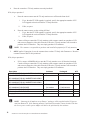
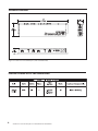
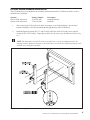
1
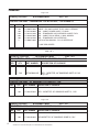
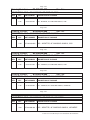
Pre-Installation & Installation Manual
Frameworx LCD
Interface
February 2012 / 57-900073-000
Frameworx LCD Interface Pre-Installation & Installation Manual
© February 2012 by the Brunswick Bowling and Billiards Corporation. All rights reserved.
Frameworx is a registered trademark of the Brunswick Bowling and Billiards Corporation.
Reorder Part No. 57-900073-000
Notice: If available, updates to this manual can be found on-line at www.brunswickbowling.com.
Confidential proprietary information. All information contained in this document is subject to change without
notice.
Brunswick Bowling & Billiards Corporation
525 West Laketon Avenue
P.O. Box 329
Muskegon, MI 49443-0329
U.S.A.
231.725.3300
2
Frameworx to LCD Interface Pre-Installation & Installation
SAFETY
Throughout this publication, “Warnings”, and “Cautions” (accompanied by one of the International
HAZARD Symbols) are used to alert the mechanic to special instructions concerning a particular
service or operation that may be hazardous if performed incorrectly or carelessly. They are defined
below.
OBSERVE AND READ THEM CAREFULLY!
These “Safety Alerts” alone cannot eliminate the hazards that they signal. Strict compliance to
these special instructions when performing the service, plus training and “Common Sense” operation are major accident prevention measures.
NOTE or IMPORTANT!: Will designate significant informational notes.
WARNING!
Will designate a mechanical or nonelectrical alert which could
potentially cause personal injury or death.
WARNING! Will designate electrical alerts which could potentially cause per-
sonal injury or death.
CAUTION! Will designate an alert which could potentially cause product
damage.
Will designate grounding alerts.
Frameworx to LCD Interface Pre-Installation & Installation
3
SAFETY NOTICE TO USERS OF THIS MANUAL
This manual has been written and published by the Service Department of Brunswick Bowling and
Billiards to aid the reader when servicing or installing the products described.
It is assumed that these personnel are familiar with, and have been trained in, the servicing or installation procedures of these products, which includes the use of common mechanic’s hand tools and
any special Brunswick or recommended tools from other suppliers.
We could not possibly know of and advise the reader of all conceivable procedures by which a
service might be performed and of the possible hazards and/or results of each method. We have not
attempted any such wide evaluation. Therefore, anyone who uses a service procedure and/or tool,
which is not recommended by Brunswick, must first completely satisfy himself that neither his nor
the products safety will be endangered by the service procedure selected.
All information, illustrations and specifications contained in this manual are based on the latest
product information available at the time of publication.
It should be kept in mind, while working on the product, that the electrical system is capable of
violent and damaging short circuits or severe electrical shocks. When performing any work where
electrical terminals could possibly be grounded or touched by the mechanic, the power to the product should be disconnected prior to servicing and remain disconnected until servicing is complete.
4
Frameworx to LCD Interface Pre-Installation & Installation
Table of Contents
Packaging......................................................................................................................................6
Site Survey..................................................................................................................................10
Interface Overview......................................................................................................................14
Interface Power Supply pre-Installation......................................................................................14
LCD Wide Screen Overhead Installation....................................................................................15
Secure Interface Assembly to to LCD hanger brackets ................................................18
Overview of Interface.................................................................................................................19
Old Frameworx CRT Monitor Cabling.......................................................................................21
TV-Only ..........................................................................................................................21
Scoresheet Video..............................................................................................................22
LCD INTERFACE CABLING...................................................................................................23
Frameworx Scorer Cabling..............................................................................................23
LCD Cabling....................................................................................................................24
DIP Switch Location and Configuration.....................................................................................25
DIP Switch Location........................................................................................................25
Configuration...............................................................................................................................26
SW1 (Switch 1)................................................................................................................26
Manufacturer of Monitor.........................................................................................26
Monitor Type............................................................................................................27
Testing......................................................................................................................27
SW2 (Switch 2)................................................................................................................27
Terminator................................................................................................................27
SW3 (Switch 3)................................................................................................................27
Software Installation...................................................................................................................28
Centermaster and Vector Plus..........................................................................................28
Command Network..........................................................................................................30
Jumper Settings and Description . ..............................................................................................31
Diagnostic LED’s description and locations ..............................................................................33
Cable Prints.................................................................................................................................35
Frameworx to LCD Interface Pre-Installation & Installation
5
Packaging
Page 1 of 1
Drawing Number:
E3-300434-000
Rev. No:
DESCRIPTION: MNC - FRAMEWORX LCD INTERFACE, FOR DOMESTIC
REV.
QTY.
PART NUMBER
1.00
1.00
1.00*
2.00
1.00
1*
57-500527-000
57-861288-000
57-861441-400
57-863035-000
57-863382-400
57-900073-000
DESCRIPTION OF PACKAGE
CABLE – IEC 320/C14 MALE TO IEC 320/C13 FEMALE
PKG. - CABLE, POWER CORD, 7.5' LONG
PKG. - FRAMEWORX LCD OVERHEAD SCRIPT FILES
PKG. - CABLE, RS232 SERIAL, 6' NULL MODEM
PKG. - FRAMEWORX LCD INTERFACE
INSTALLATION MANUAL - FX LCD INTERFACE
* = ONE PER CENTER
Page 1 of 1
E3-300427-000
Drawing Number:
Rev. No:
DESCRIPTION: MNC - 46" SAMSUNG LCD DISPLAY, 110V
REV.
QTY.
PART NUMBER
1.00
57-863364-002
Drawing Number:
DESCRIPTION OF PACKAGE
PKG. - MONITOR, 46" SAMSUNG 460FP-3 110V
Page 1 of 1
E3-300418-000
Rev. No:
DESCRIPTION: MNC - 40" SAMSUNG LCD DISPLAY, 110V
REV.
QTY.
PART NUMBER
1.00
57-863355-002
DESCRIPTION OF PACKAGE
PKG. - MONITOR, 40" SAMSUNG 400FP-3, 110V
Page 1 of 1
Drawing Number:
E3-300417-000
Rev. No:
DESCRIPTION: MNC - 32" SAMSUNG LCD DISPLAY, 110V
REV.
6
QTY.
PART NUMBER
1.00
57-863356-002
DESCRIPTION OF PACKAGE
PKG-MONITOR, 32" SAMSUNG 320MP-3,110V
Frameworx to LCD Interface Pre-Installation & Installation
Page 1 of 1
Drawing Number:
E3-300433-000
Rev. No:
DESCRIPTION: MNC - 46" SAMSUNG LCD DISPLAY, 220V
REV.
QTY.
1.00
PART NUMBER
57-863369-002
DESCRIPTION OF PACKAGE
PKG. - MONITOR, 46" SAMSUNG 460MX-3, 220V
Page 1 of 1
Drawing Number:
E3-300432-000
Rev. No:
DESCRIPTION: MNC - 40" SAMSUNG LCD DISPLAY, 220V
REV.
QTY.
PART NUMBER
1.00
57-863368-002
DESCRIPTION OF PACKAGE
PKG. - MONITOR, 40" SAMSUNG 400MX-3, 220V
Page 1 of 1
Drawing Number:
E3-300426-000
Rev. No:
DESCRIPTION: MNC - 32" SAMSUNG LCD DISPLAY, 220V
REV.
QTY.
1.00
PART NUMBER
57-863363-002
DESCRIPTION OF PACKAGE
PKG. - MONITOR, 32" SAMSUNG 320MX-3, 220V
Page 1 of 1
Drawing Number:
E3-300419-000
Rev. No:
DESCRIPTION: MNC - 46" SAMSUNG LCD DISPLAY, JAPANESE
REV.
QTY.
1.00
PART NUMBER
57-863359-002
DESCRIPTION OF PACKAGE
PKG. - MONITOR, 46" SAMSUNG 460MX-3, JAPANESE
Page 1 of 1
Drawing Number:
E3-300420-000
Rev. No:
DESCRIPTION: MNC - 40" SAMSUNG LCD DISPLAY, JAPANESE
REV.
QTY.
PART NUMBER
1.00
57-863360-003
DESCRIPTION OF PACKAGE
PKG. - MONITOR, 40" SAMSUNG 400MX-3, JAPANESE
Frameworx to LCD Interface Pre-Installation & Installation
7
Page 1 of 1
Drawing Number:
E3-300421-000
Rev. No:
DESCRIPTION: MNC - 32" SAMSUNG LCD DISPLAY, JAPANESE
REV.
QTY.
PART NUMBER
1.00
57-863361-002
DESCRIPTION OF PACKAGE
PKG. - MONITOR, 32" SAMSUNG 320MX-3, JAPANESE
Page 1 of 1
Drawing Number:
E3-300448-000
Rev. No:
N/C
DESCRIPTION: MNC - LCD MOUNTING BRACKET, WIDESCREEN, FOR CONTINUOUS
REV.
QTY.
PART NUMBER
1.00
57-863325-000
DESCRIPTION OF PACKAGE
PKG. - UNIVERSAL MOUNTING BRACKET, WIDESCREEN
FOR CONTINUOUS OR STD. SUPPORT STRUCTURE
Page 1 of 1
Drawing Number:
E3-300449-000
Rev. No:
DESCRIPTION: MNC - LCD MOUNTING BRACKET, WIDESCREEN FOR LOW PROFILE
REV.
QTY.
PART NUMBER
1.00
57-863390-000
DESCRIPTION OF PACKAGE
PKG - LCD MOUNTING BRACKET, WIDESCREEN
FOR LOW PROFILE SUPPORT STRUCTURE
Page 1 of 1
Drawing Number:
E3-280101-000
Rev. No:
N/C
DESCRIPTION: MNC - VECTOR ANIMATIONS FOR
FRAMEWORX - SET 1
REV.
8
QTY.
PART NUMBER
1.00
57-863351-400
DESCRIPTION OF PACKAGE
PKG. – VECTOR ANIMATIONS FOR FRAMEWORX - SET 1
Frameworx to LCD Interface Pre-Installation & Installation
Page 1 of 1
Drawing Number:
E3-280102-000
Rev. No:
N/C
DESCRIPTION: MNC - VECTOR ANIMATIONS FOR
FRAMEWORX - SET 2
REV.
QTY.
PART NUMBER
1.00
57-863352-400
DESCRIPTION OF PACKAGE
PKG. – VECTOR ANIMATIONS FOR FRAMEWORX - SET 2
Page 1 of 1
Drawing Number:
E3-280103-000
Rev. No:
N/C
DESCRIPTION: MNC - VECTOR ANIMATIONS FOR
FRAMEWORX - SET 3
REV.
QTY.
PART NUMBER
1.00
57-863353-400
DESCRIPTION OF PACKAGE
PKG. – VECTOR ANIMATIONS FOR FRAMEWORX - SET 3
Page 1 of 1
Drawing Number:
E3-280104-000
Rev. No:
N/C
DESCRIPTION: MNC - VECTOR ANIMATIONS FOR
FRAMEWORX - FULL SET
REV.
QTY.
PART NUMBER
1.00
1.00
1.00
57-863351-400
57-863352-400
57-863353-400
DESCRIPTION OF PACKAGE
PKG. – VECTOR ANIMATIONS FOR FRAMEWORX - SET 1
PKG. – VECTOR ANIMATIONS FOR FRAMEWORX - SET 2
PKG. – VECTOR ANIMATIONS FOR FRAMEWORX - SET 3
Page 1 of 1
Drawing Number:
E3-300447-000
Rev. No:
N/C
DESCRIPTION: MNC - LOW PROFILE OVERHEAD SUPPORT STRUCTURE, HANGING
HARDWARE
REV.
QTY.
PART NUMBER
1.00
1.00*
57-863394-000
57-301036-000
DESCRIPTION OF PACKAGE
PKG - HANGING HARDWARE, WIDESCREEN
ASSY - MONITOR CRIMP GAUGE
*=ONE PER CENTER
Frameworx to LCD Interface Pre-Installation & Installation
9
Site Survey
This site survey is to be completed by the sales team before order submission.
1.
Verify the type of "Remote Video Board" the center has. There are two locations the "Remote Video
Boards" can be located, in the Lane Group Processor (LGP) or the shaver console. Refer to Figures 1
& 2. The LGP is located on the curtain wall. If there is not an LGP then the "Remote Video Board"
is located inside the shaver scoring console.
Figure 1. Lane Group Processor Remote Video Board Location
Figure 2. Shaver Console Remote Video Processor
10
2.
Refer to Figures 1 and 2 for the location of the "Remote Video Board" part number.
Frameworx to LCD Interface Pre-Installation & Installation
IMPORTANT! The "Remote Video Boards" do not have to be removed to identify the part number.
a. Does the center have video board, part number 57-300103-4xx? ______
b. Does the center have the 2000 video board, part number 57-301081-4xx? ______
c. Does the center have both video boards? ______
NOTE: Check ALL Lane Group Processors or if they do not have any Lane Group Processors,
shaver scoring consoles will need to be checked for the type of video boards
NOTE: If the center does not have any existing overheads and would like to add LCD overheads,
an exception request will need to be processed.
3.
What type of Frameworx LCD upgrade will be ordered?
Description
FX LCD UPGRADE 32" SAMSUNG FOR ALL MARKETS
INCLUDING ASIA EXCEPT EUROPE
FX LCD UPGRADE 40" SAMSUNG FOR ALL MARKETS
INCLUDING ASIA EXCEPT EUROPE
FX LCD UPGRADE 46" SAMSUNG FOR ALL MARKETS
INCLUDING ASIA EXCEPT EUROPE
FX LCD UPGRADE 32" SAMSUNG FOR EUROPE
FX LCD UPGRADE 40" SAMSUNG FOR EUROPE
FX LCD UPGRADE 46" SAMSUNG FOR EUROPE
Guidance
Model No.
Per monitor
E3-300434-032
Per monitor
E3-300434-040
Per monitor
Per monitor
Per monitor
Per monitor
E3-300434-046
E3-300435-032
E3-300435-040
E3-300435-046
NOTE: The customers are NOT allowed to provide their own LCD overhead.
NOTE: All electronics are capable of 120/230 volts and 50/60 hertz.
QTY
Frameworx to LCD Interface Pre-Installation & Installation
11
4.
Does the center have TV-Only monitors currently installed?
If No, skip to question 5.
a.
b.
c.
Does the center want to turn the TV-only monitor on or off from the front desk?
i.
If yes, then the FX LCD upgrade is required; specify the appropriate number of FX
LCD upgrade tab codes needed for TV-Only monitors.
ii.
If No, see part c.
Does the center want to use the existing AV Box?
i. If yes, then the FX LCD upgrade is required; specify the appropriate number of FX
LCD upgrade tab codes needed for TV-Only monitors.
ii. If No, see part c.
Centers willing to control the TV-only monitors with a remote control can purchase a VCR
and run new composite video cable from the VCR to the TV-only monitors will not need to
purchase the LCD Interface. They can simply purchase LCD monitors.
NOTE: The customer is responsible to purchase and install all equipment for TV-only monitors
5.
ONLY applies if Question 4 is no, the customer does not have TV-Only with Frameworx. Does the
customer want to add TV-Only monitors?
If No, skip to question 6.
a.
If Yes, centers will NOT be able to turn the TV-only monitor on or off from the front desk.
Centers willing to control the TV-only monitors with a remote control can purchase a VCR
and run new composite video cable from the VCR to the TV-only monitors will not need to
purchase the LCD Interface. They can simply purchase LCD monitors.
Description
32" SAMSUNG FOR ALL MARKETS INCLUDING ASIA EXCEPT EUROPE
40" SAMSUNG FOR ALL MARKETS INCLUDING ASIA EXCEPT EUROPE
46" SAMSUNG FOR ALL MARKETS INCLUDING ASIA EXCEPT EUROPE
32" SAMSUNG FOR EUROPE
40" SAMSUNG FOR EUROPE
46" SAMSUNG FOR EUROPE
Hanging Brackets
12
Guidance
Package #
Per monitor
Per monitor
57-863035-000
Per monitor
Per monitor
Per monitor
Per monitor
Per Monitor
57-863364-000
57-863363-000
57-863368-000
57-863369-000
57-863325-000
QTY
57-863355-000
NOTE: “Samsung for all markets except Europe” packages will be supplied with a USA power
cord from Brunswick. If the Samsung monitor is purchased for another country besides USA then
the correct power cord or power adapter will have to be purchased by the customer.
Frameworx to LCD Interface Pre-Installation & Installation
6.
What type of front desk does the center have?
a. Command Network
_______
b. Center Master
_______
c. Vector Plus
_______
7.
What version of Frameworx scorer software does the customer have? _______
NOTE: Command Network must have Frameworx scorer software version 5.6. Vector Plus and
Centermaster must have Frameworx scorer software version 6.3. If the customer does not have the
proper software, please contact the CRC on behalf of the customer to obtain these disks. Provide
this site survey to the CRC.
8.
The LCD overheads require different electrical requirements than the old CRT overheads. Please
review the information below with the customer to inform them of their additional electrical responsibilities.
a. Isolated Ground (IG) outlet is required for the LCD Overhead.
b.
Isolated Ground (IG) outlet is required for the Frameworx LCD Interface.
c. LCD WITH INTERFACE ELECTRONICS
TOTAL AMPERAGE PER ONE OVERHEAD (120/230 VOLT)
32" LCD
2.0/1.0
40" LCD
3.0/1.5
9.
46" LCD
3.5/1.75
What is the ceiling height, from the lane surface over the approach area where monitors will be
located? _______
a.
For 32" LCD we recommend 10’-6" (3.2m) ceiling heights, minimum of 9’-6" (2.9m).
b.
For 40" LCD we recommend 10’-10" (3.3m) ceiling heights, minimum of 9’-10" ( 3.0m).
c.
For 46" LCD we recommend 11’-1" (3.4m) ceiling heights, minimum of 10’-1" (3.1m).
NOTE: The LCD monitor may be installed with ceilings lower than the minimum ceiling height distance, but the customer should be aware the height from the lane to the bottom of the monitor would
be less than 89."
IMPORTANT!: The site survey and overhead certificate must be completed and sent to Contract
Management before the contract can be approved and shipped.
Frameworx to LCD Interface Pre-Installation & Installation
13
Interface Overview
Figure 3. Frameworx to LCD Interface (P/N 57-863382-400)
Interface Power Supply pre-Installation
14
Frameworx to LCD Interface Pre-Installation & Installation
LCD Wide Screen Overhead Installation
The LCD Wide Screen Overhead must be assembled with brackets and the LCD Interface before it can be
installed on the weldment.
Quantity
One per LCD widescreen One per LCD widescreen
Package Number
57-863325-000 57-863326-000
Description
Hanging Brackets
Hardware
1.
After removing the LCD wide screen from it's package, set on foam packaging. Be sure not to
scratch or damage LCD while assembling the hanging brackets and LCD Interface.
2. Install the hanging brackets (P/N 57-500756-001) to the back of the LCD wide screen with the
washers (P/N 11-053784-009). Depending on the LCD, the screws may be different. Refer to Figure 1.
NOTE: The bolt pattern on the LCD wide screen allows for a variety of configurations for the
hanging brackets. Mount the brackets on the LCD wide screen at the two outermost positions so the
brackets are as far apart as possible.
Figure 1. Install the Hanging Brackets
Frameworx to LCD Interface Pre-Installation & Installation
15
3. Hang the LCD wide screen on the weldment. Use the handles of the LCD wide screen to raise into
position. Refer to Figure 2.
Figure 2. Hang the LCD Wide Screens
16
Frameworx to LCD Interface Pre-Installation & Installation
4. Install the bracket lock (P/N 57-500757-001), to the hanging bracket. After the bracket lock is installed, use the M6 x 40mm screw (P/N 11-053784-009) to secure it in place. Refer to Figure 3.
Figure 3. Install the bracket lock
Frameworx to LCD Interface Pre-Installation & Installation
17
Secure Interface Assembly to to LCD hanger brackets
Figure 4. Secure LCD Interface
18
Frameworx to LCD Interface Pre-Installation & Installation
Overview of Interface
Figure 5. Frameworx LCD Interface Board I/O Connectors Location and Description
The functions of the connectors and components of the Frameworx LCD Interface are:
(1)
Video In - The video input connector for the Frameworx video signal.
(2)
Video Out - The loop through Frameworx video signal (to the next lane)
(3)
LAN IN: The RS-485 serial communication input connector for the Frameworx communication
channel.
(4)
LAN OUT: The loop through Frameworx communication signal (to the next lane).
Frameworx to LCD Interface Pre-Installation & Installation
19
(5)
Power In - Use a power cable from an outlet of the building power to the "Power In" port of the
LCD
(6)
Power Out - Use power cable (57-500527-000) to power the LCD from the "Power Out" port of the
Interface
(7)
RGB Output - RGB output is red, green, blue and composite sync output for any LCD monitor that
can accept analog RGB video signals with Composite Sync. The horizontal frequency is 15.72 kHz
and vertical is 59.92 Hz.
(8)
S-Video In - Not Used
(9)
RS232 to LCD - An RS-232 serial communication channel connected to the LCD monitor.
20
Frameworx to LCD Interface Pre-Installation & Installation
Old Frameworx CRT Monitor Cabling
TV-Only
Figure 6. Old - TV-Only Overhead Monitor Cabling
Frameworx to LCD Interface Pre-Installation & Installation
21
Scoresheet Video
Figure 7. Old - Scoresheet Video Overhead Monitor Cabling
22
Frameworx to LCD Interface Pre-Installation & Installation
LCD INTERFACE CABLING
Frameworx Scorer Cabling
Figure 8. New - LCD Interface to LCD Cabling
Frameworx to LCD Interface Pre-Installation & Installation
23
LCD Cabling
Figure 9. Route to LCD
24
Frameworx to LCD Interface Pre-Installation & Installation
DIP Switch Location and Configuration
DIP Switch Location
Figure 10. DIP Switches
Figure 10 shows the Frameworx LCD Interface PCB DIP switch locations and descriptions:
(1)
SW1: position switch for LCD monitor selection. See Figure 11 for switch settings and LCD monitor selection.
(2)
SW2: 4 position DIP switch for video cable termination. The switch default is all switches are ON.
The video cable is then terminated for each signal, red, green, blue and composite snyc with 124
Ohms resistors. Refer to Figure 12.
NOTE:Termination is needed for reducing the signal loss in long cables.)
(3)
SW3: 4 position DIP switch for video input selection. Default setings are all 4 to OFF position.
Refer to Figure 13.
Frameworx to LCD Interface Pre-Installation & Installation
25
Configuration
SW1 (Switch 1)
Manufacturer of Monitor
Brand Compatibility
Description LEGACY
LEGACY monitor is selected. This is
an unsupported monitor.
NEC
NEC 4000 NEC 4000 monitor is selected. This is
an unsupported monitor.
NEC
NEC MULTISYNC NEC MultiSync monitor is selected.
This is a supported monitor.
LG
LG L3200T LG L3200T monitor is selected. This is
an unsupported monitor.
SAMSUNG
SYNCMASTER 323T & 403T SAMSUNG Sync Master 323T
and 403T is selected. This is a
supported monitor.
OLEVIA
OLEVIA 232 OLEVIA 232 is selected. This is an
unsupported monitor.
OLEVIA
OLEVIA 242 & 237 OLEVIA 242 & 237 is selected.
This is an unsupported monitor.
OLEVIA
OLEVIA 232T12, 232 & S13 OLEVIA 232T12, 232 & S13 is
selected.
This is an unsupported monitor.
SAMSUNG
SYNCMASTER MX SERIES SAMSUNG SYNCMASTER
MX_SERIES monitor is selected.
This is a supported monitor.
DEBUG MONITOR DEBUG_MONITOR monitor is
selected. This is a supported
monitor type. Selecting this monitor sends English text out of the
RS-232 port at 9600 baud.
Figure 11. Switch 1 - Manufacturer of Monitor
26
Frameworx to LCD Interface Pre-Installation & Installation
Switch Setting
Monitor Type
Switch Settings
OVERHEAD TV this Frameworx LCD controller is connected to a Center TV.
OVERHEADSCORE SHEET MONITOR this Frameworx LCD controller is connected to an Overhead Scorer Monitor.
Figure 12. Switch 1 - Monitor Type
Testing
Switch Settings
OVERRIDE 1 forces the monitor ON unconditionally and ignores Scorer
communications.
OVERRIDE 2 allows the Scorer to control the monitor. Figure 13. Switch 1 - Testing
SW2 (Switch 2)
Terminator
Switch Settings
The switch default is all switches are ON. The video cable is then terminated for each signal, red, green, blue and composite sync with 124 Ohms resisters.
Figure 14. Switch 2 - Testing
SW3 (Switch 3)
Switch Settings
Video is RGB from Frameworx scorer. Default position.
Troubleshoot video input is "S-Video" signal.
Troubleshoot output video is color bar generated from Frameworx interface board
Figure 15. Switch 3
Frameworx to LCD Interface Pre-Installation & Installation
27
Software Installation
IMPORTANT!: Install Batch files before upgrading CRT overheads to LCD this will avoid
graphic card compatibility problems.
1.
Log onto the system with an user I.D that has administrative rights.
2.
Load the CD on the Centermaster/Vector Plus server.
Description of files to be downloaded:
-
FRXLCD.SCP script file - Configures the Frameworx Scorer to use LCD overheads.
UNFRXLCD.SCP script file - Changes the Frameworx Scorer to use CRT overheads.
CER_CHIP.CRT - data files used by the FRXLCD.SCP script file.
CER_2093.CRT - data files used by the FRXLCD.SCP script file.
Centermaster and Vector Plus
1.
Open the Office application and select "Scorer Maintenance" .
2.
From "Scorer Maintenance" drop down menu select “Operations.”
Figure 16. Centermaster and Vector Plus
28
Frameworx to LCD Interface Pre-Installation & Installation
3.
Type FRXLCD.SCP in the other box.
Figure 17. Centermaster and Vector Plus
Frameworx to LCD Interface Pre-Installation & Installation
29
4. Download the "FRXLCD.SCP" file to the Frameworx Scorer by pressing the “Other” button.
NOTE: The Frameworx scorer will reboot automatically after the file is downloaded.
Figure 18. Software Installation
To use the CRT overheads follow steps 1 through 4 except use file “UNFRXLCD.SCP” in step 3.
Command Network
1.
Load the floppy or the Card Net/Dsk card server.
At the Lane Status screen:
1. Press SCORER STATUS.
2. Type the lane number(s) that will be affected and press ADJUST.
3. Type your password and press ENTER.
30
4. Type FRXLCD and press ENTER.
Frameworx to LCD Interface Pre-Installation & Installation
NOTE: The Frameworx scorers will reboot automatically after the file is downloaded. During this
time the screen will display “Processing.” After the Frameworx score reboot is complete, the screen
will display “Successful” or “Failed.” When the scorers have
finished rebooting successfully, you may issue the lanes as normal. If the function failed,
contact the Brunswick Customer Response Center for assistance.
Jumper Settings and Description
Figure 19. Jumper locations
Figure 17 shows the Frameworx LCD board interface jumpers location and default settings:
(1)
Jumper, JP1 - is the Composite or Video input select jumper for U1 sync separator chip. Default
setting is 2-3 position, input to the U1 is Composite Sync signal.
(2)
Jumper, JP2 - is the watchdog disable jumper for U10 microcontroller. Default setting is open.
(3)
Jumper, JP3 - is the RGB or PrPbY signal select jumper. Default setting is 1-2 position, input to the
RGB decoder chip U13 is component PrPbY video. Jumper on 2-3 position will change input to the
RGBHV signal from Frameworx scorer. Setting to 2-3 position will follow RGB input signal from
the scorer direct to the 15-pins D-sub RGB output connector J5.
(4)
Jumper, JP4 - is the Composite sync signal selection jumper for PrPbY conversion. Default setting
is 1-2 position, the composite sync is same as scorer composite sync signal. Position 2-3 is selection
composite sync from sync separator chip U1.
Frameworx to LCD Interface Pre-Installation & Installation
31
(5)
Jumper, JP5 - is the vertical sync signal selection jumper for PrPbY conversion. Default is open, no
vertical sync selection.
(6)
Jumper, JP6 - is the horizontal sync signal selection jumper for PrPbY conversion. Default setting is
2-3 position, horizontal sync is same as composite sync from scorer.
(7)
Jumper, JP7 - is the Vertical Sync select jumper. Default setting is open position. Jumper closed
will connect vertical sync signal on pin 14 at output RGB connector J5.
(8)
Jumper, JP8 - is the watchdog disable jumper for U20 microcontroller. Default setting is open.
(9)
Jumper, JP9 - is the video output gain for RGB driver U13. Default is closed and gain is set to 2.
Open will set gain to 1.
(10)
Jumper, JP10 - is the Composite or Horizontal Sync select jumper. Default setting is 1-2 position,
on pin 13 at RGB connector J5 is Composite Sync signal. Setting to 2-3 position will connect Horizontal Sync signal on pin 13 at output RGB connector J5.
(11)
Jumper, JP11 - is the reset jumper for video circuitry. Default setting is open. Close jumper will
have reset control for video chipsets to be attached with watchdog timer.
(12)
Jumper, JP12 - is Horizontal Sync positive or negative edge select jumper. Default setting is 1-2
position, positive edge for Horizontal sync. Setting to 2-3 position is negative edge selection for
Horizontal Sync.
(13)
Jumper, JP13 - is Vertical Sync positive or negative edge select jumper. Default setting is 1-2 position, positive edge for Vertical Sync. Setting to 2-3 position is negative edge selection for Vertical
Sync.
(14)
Jumper, JP14 - is the RS-485 communication test jumper. Default setting is open.
(15)
Jumper, JP15 - is the push button reset jumper for I2C microcontroller U20. Default setting is
closed.
(16)
Jumper, JP16 - is the I2C jumper for programming video chipsets over J9 connector. Default setting
is open, video chipsets is programmed from I2C microcontroller U20.
(17)
Jumper, JP17 - is the power down jumper for video chipsets. Default setting is open, video chipsets
is always powered up.
(18)
Jumper, JP18 - is the address select jumper for video decoder U29. Default setting is open, video
decoder is on address 42H. Jumper closed the video decoder address is 40H.
(19)
Jumper, JP19 - is the RS-485 cable termination jumper. Default setting is in unterminated “U” position, pins 2-3.
(20)
Jumper, JP20 - is the Field Synchronization Output Signal for video decoder U29. Default setting is
1-2 position, the video decoder synchronized video encoder U26 with the field signal. Jumper setting
on 2-3 position, the video decoder synchronized video encoder with the vertical sync signal.
32
Frameworx to LCD Interface Pre-Installation & Installation
(21)
Jumper, JP21 is the CS_ON select jumper. Default setting is on pins 2-3. The CS_ON signal will be
self generated when Composite Sync signal from Frameworx scorer is present. With jumper on pins
1-2 position, the CS_ON signal will be generated and controlled with microcontroller. CS_ON signal
can control optional relay if it is connected on J13 connector.
(22)
Jumper, JP22 - is the address select jumper for optional I2C EEPROM U28. Default setting is open,
EEPROM is on address 01H. Jumper closed, the EEPROM address is 00H.
(23)
Jumper, JP23 - is the optional relay control select jumper. Jumper on pins 1-2, the relay is always
ON, jumper on pins 2-3 the relay control is generated from Composite Sync or from microcontroller.
If sync is present the relay is ON if sync is not detect the relay is OFF. Default setting is on 2-3 position.
(24)
Jumper, JP24 - is the address select jumper for video encoder U26. Default setting is open, video
decoder is on address 56H. Jumper closed the video decoder address is 54H.
Diagnostic LED’s description and locations
Figure 20. LEDs
Figure 20 shows the Frameworx LCD interface board diagnostic LED’s location and description:
(1) LED, D1 - is the RS-485 receiving LED. The LED is blinking when the microcontroller is receiving
data from the RS-485 serial network.
Frameworx to LCD Interface Pre-Installation & Installation
33
(2)
LED, D4 - is the RS-485 transmitting LED. The LED is blinking when the microcontroller is transmitting data to the RS-485 serial network.
(3)
LED, D5 - is a heart-beat LED. The LED is blinking when the microcontroller U10 is running.
(4)
LED, D8 - is board transmitting or receiving LED for RS-485 communication to the Frameworx
Scoring computer. The LED is light ON if the board is in receiving mode. The LED is turn OFF if
interface board is in transmitting mode.
(5)
LED, D12 - is a +5Vdc isolated LED. The LED is light ON when +5Vdc isolated is present on the
interface board.
(6)
LED, D17 - is a heart-beat LED. The LED is blinking when the microcontroller U20 is running.
(7)
LED, D18 is for an optional relay ON/OFF LED. The LED is light ON when the optional relay is in
ON state. The optional relay could be connected to the Frameworx LCD interface board over 2 pins
J5 connector, and it could be use for controlling the power to the LCD monitors or TV. The relay
could be turn ON when composite sync is present or control by microcontroller or set to be always
ON with jumper JP23 on position 1-2.
(8)
LED, D19 - is a -9Vdc LED. The LED is light ON when -9Vdc is present on the interface board.
(9)
LED, D24 - is a -5Vdc LED. The LED is light ON when -5Vdc is present on the interface board.
(10)
LED, D25 - is a +5Vdc LED. The LED is light ON when +5Vdc is present on the interface board.
(11)
LED, D27 - is a +3.3Vdc LED. The LED is light ON when +3.3Vdc is present on the interface
board.
(12)
LED, D28 - is a +9Vdc LED. The LED is light ON when +9Vdc is present on the interface board.
34
Frameworx to LCD Interface Pre-Installation & Installation
Cable Prints
Primary Console Global Video Front Control Desk Cable Assembly (P/N 57-300004-000)
Overhead Monitor Video Input Cable Assembly (P/N 57-300026-000)
Overhead Monitor Video Input Cable Assembly (P/N 57-300027-000)
Local LAN Frameworx 27" TV-Only Overhead Cable Assembly (P/N 57-300031-000)
Frameworx to LCD Interface Pre-Installation & Installation
35
Overhead TV-Only Lane Pair, to Lane Pair Cable Assembly (P/N 57-300139-000)
Cable IEC 320 / C14Male to EC 320 / C13 Female. Length 1 Meter (P/N 57-500527-000)
36
Frameworx to LCD Interface Pre-Installation & Installation