1
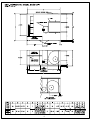
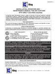
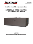
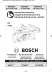
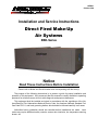
ISEBD-1
October 2009
Installation and Service Instructions
Direct Fired Make-Up
Air Systems
EBD-Series
Notice
Read These Instructions Before Installation
Please refer to Model and Serial Number when corresponding with the factory.
The purpose of the following instructions is to present a guide for proper installation and
operation of this equipment. We recommend that this manual be readily available to operating
personnel for reference as an aid for trouble diagnosis and proper maintenance.
This equipment shall be installed and wired in accordance with the regulations of the National Board of Fire Underwriters National Electric Code, the American National Standard Fuel
Gas Code Z223.1, and local governing bodies, which should be followed carefully in all cases.
Authorities having jurisdiction should be consulted before installations are made. Local
codes may require additional safety controls, access door interlocks, low temperature warning
buzzer, etc.
GENERAL INFORMATION
FACTORY FLAME TEST
All Hastings heaters are given a complete flame test and safety control check-out before shipping.
A copy of the flame test report is available upon request.
CHECK-UP ON ARRIVAL
All heaters are thoroughly checked by a shipping inspector before they are accepted by the carrier. Upon arrival the heater should be inspected by the customer. If any damage has occurred in
transit, an immediate claim should be filed with the carrier. Due to the widely varying conditions under which heaters are transported to the job, unloaded and installed, it is impossible for Hastings to
assume responsibility for handling in transit. Check to see if unmounted items are included with shipment.
HANDLING THE HEATER
The heater has lifting lugs for crane hook-up. Hooks, jacks, or chains must not be applied around
casing or control box.
* * *
INSTALLATION
POSITIONING THE HEATER
Heater should be installed so that it is level. Allow 48” clearance at the front and control side of
the heater and 18” on the bottom, top and other side. Air intake to the unit should not be restricted in
any manner.
Install heater such that the ignition control system is not directly exposed to water spray, rain or
dripping water.
Lift unit with suitable spreader bar at the (4) points on the support frame or proper lifting equipment.
WIRING
Electrical connections must be in accordance with all local and national codes.
If not supplied by the factory, provide an electric switch having adequate ampacity (see specification plate on heater for voltage and ampacity) and shall be installed in accordance with Article 430 of
the National Electrical Code, ANS/NFPA 70.
Refer to markings on heater control box for locations for field installed wiring and control wiring.
PIPING
Gas piping should be sized adequately, in accordance with the American National Standard Fuel
Gas Code Z223.1.
Main gas pressure regulator is field installed by installer.
***
TYPICAL OPERATING SEQUENCE
Blower switch should be turned on to start the fan. Placing season switch in winter position energizes the gas control system. If all limit switches are satisfied, the pilot valve will be opened and pilot
gas automatically spark ignited. When the flame sensor senses the pilot flame, the main valve will be
opened through terminals on the flame safeguard relay. The modulating gas valve will control the
flow of gas to the burner to maintain the discharge temperature. The controller should be set for the
desired discharged temperature.
1
START-UP INSTRUCTIONS
After the heater has been positioned and all service connections made, complete the following
check-up before starting the unit. Keep in mind the fact that the heater may have been subject to severe jolts during transportation and handling. The check-up is essential to make sure that the heater is
in the same operating condition as it was at completion of the factory flame test.
1.
Make sure all field wiring and gas piping are in accordance with local and national codes. Check
incoming power—making sure it is the same as the nameplate voltage.
2.
Refer to heater rating plate for determining the minimum gas supply pressure for obtaining the
maximum gas capacity for which this heater is specified.
3.
Close gas hand valves and pilot cock.
4.
Set all switches to “Off” position.
5.
Wait five minutes.
6.
Push reset button on electronic relay.
7.
Push manual reset button on gas pressure switches, starters, and limit control if necessary.
8.
The unit is equipped with a modulating gas valve which is controlled by a discharge sensor located in the discharge opening. Check to see that the sensor is properly positioned. Set the
selector dial for desired discharge temperature.
9.
Check if limit control is locked at 180 deg. F. discharge temperature.
10.
Check all gas piping for leaks.
11.
Turn on main power.
12.
Before firing the burner, check the motor, belts and pulleys for proper adjustment, etc. Turn
the blower switch on and run the fans. Check the current draw of the motor.
13.
If the motor current is excessive, adjust the variable speed pulley (standard through 10 hp) on the
motor to lower the amp draw on the motor. Caution: Current readings should be taken with
the access door in place.
14.
Set temperature controller(s) to call for heat.
15.
Open hand valve and pilot cock.
16.
Set season switch to “Winter” position.
17.
The pilot will light and then the main flame will come on.
18.
The burner will come on at high fire initially, then gradually modulate down. While the unit is on
high fire, check the flame length. It must be approximately 14” - 18” beyond end of burner.
Check the manifold pressure—should not exceed operating pressure noted on unit spec plate.
Check temperature rise and/or gas rate. If too high, set at desired rate by reducing high fire
setting for “MR” or “M” modulating valve. If no high fire adjustment is available, reset modulating control to design temperature rise plus current outdoor temperature to approximate full input. If input is too low, increase setting on main regulator (“M” valve only) but not past point
where no further pressure increase is evident. With burner running, reset modulating control
point less than incoming air temperature to drive valve to low fire position. Then gradually reduce low fire stop, or bypass till fire tends to go out. Increase to the smallest stable (1” - 1-1/2”
flame length), full length fire. If a local weak spot appears, check for clogged low fire air ports
or extreme turbulence at affected portion.
Make low fire adjustments patiently. Due to low
gas flow rate, response to adjustments will be slow.
2
Wiring Diagrams
MT1-12
TS114
TS1007
MT1-12
TS114
TD114
T115
TD114
TRANS.
TRANS.
VALVE
VALVE
LO-FIRE
SWITCH
LO-FIRE
SWITCH
1
2
3
4
6
5
1
8
7
A1014
1
2
DECREASE
3
4
INCREASE
5
6
3
4
6
5
7
8
Figure 3
BASIC SYSTEM WITH INLET AIR
2. Remove seal cap (A), Figure 6, and turn regulator pressure
adjusting screw to obtain desired manifold pressure. (Clockwise rotation increases pressure.)
3. Reconnect the wires to terminal #4.
BASIC SYSTEM WITH ROOM OVERRIDE
Temperature
Calibration-
2
Figure 2
7
8
MODULATOR
MODEL NO. A1014
SENSITIVITY
DO
Figure 4
NOT
TAMPER
Note: The components of this system are individually calibrated and are not part
of a matched set. When it has been positively determined that there is calibration problem with the entire system the most convenient component may be
used to correct the calibration. It is necessary to place an accurate temperature
measuring device as near the Discharge Air Sensor as possible.
Set the Remote Temperature Selector at least 10 deg. above outside air temperatures.
If calibrating at the Amplifier - adjust calibration potentiometer (A), Figure
4, until temperature reads the same as the set temperature. If the temperature
is below the set point, then rotate calibration potentiometer (A) clockwise. If the
temperature is above the set point, rotate the potentiometer counter clockwise.
OVERRIDE TEMPERATURE
SELECTOR DIAL
1
2
A
Figure 6
A B
MR212
Valve
D
C
Low Fire or By-Pass Adjustment.
1. Disconnect wire from terminal # 8 in the Amplifier, Figure 4, this
causes valve to call for continuous low fire.
2. Remove cap (B), Figure 6, and loosen lock screw (C). Turn (D)
to desired low fire adjustment. (Clockwise rotation reduces minimum flow rate.)
3. Tighten set screw (C), replace cap (B) and reconnect wire to terminal # 8.
M611 Valve High Fire Manifold Adjustment
1. Disconnect wires from terminal # 4 in the Amplifier, Figure 4,
this causes the valve to call for continuous high fire.
2. Adjust the pressure regulator to obtain the desired manifold
pressure (7" w.c. maximum).
3. Reconnect the wires to terminal #4.
Figure 5
M611
Valve
If calibrating the Remote Temperature Selector - if measured
temperature is below set temperature, rotate the calibration potentiometer (A), Figure 5, clockwise until the correct temperature is obtained. If the temperature is above the set point, the potentiometer
(A) should be turned counter-clockwise.
Proceed slowly with the above steps so as to allow the temperature
measuring instrument to catch up with the change in temperature.
A
Low Fire or By-Pass Adjustment
B
1. Disconnect wire from terminal #8 in the Aplifier, Figure 4, This
causes valve to call for continuous low fire.
2. Remove cap (A), Figure 7, and turn adjusting screw (B) to desired low fire adjustment. (Use 1/8" Allen Wrench.) For convenience,
two adjustment positions are provided on opposite sides of the valve.
Usually, The less accessible of these is in the closed position, so the
desired setting can be made from the front of the manifold.
3. Replace cap (A), and reconnect wire to terminal # 8.
Valve Adjustments
Note: Low fire adjustment should be checked whenever the high
fire adjustment is changed.
MR 212 Valve High Fire Manifold Adjustments
1. Disconnect wires from terminal #4 in the Amplifier, Figure 4.
This causes the valve to call for continous high fire.
TO BURNER
Figure 7
3
TROUBLE SHOOTING CHART
First make certain of fuel and power supply. A closed hand shut-off valve, blown fuse in main power
supply line or burner control circuit is often the cause of trouble. Make sure voltage at the control box is
within plus or minus ten volts of that specified. Individual control instruction sheets are provided with
unit. These, together with the schematic wiring diagram, should provide the necessary information to
find the problem. Some general checks to make are given below.
Nature of Trouble
1. Fans do not operate.
Possible Causes
1.
No electrical supply.
1.
Check entrance cable.
2.
Loose wire leads.
2.
Check all fan circuit connections.
3.
Main disconnect switch not 3.
fully closed.
See that switch knives are fully inserted.
4.
Blown fuses.
Locate and replace.
5.
Linestarter holding coil defec- 5.
tive.
Check terminals with test light.
If current is present, replace coil.
6.
Fan motor defective.
6.
Replace or repair.
7.
Starter out on overload.
7.
Reset.
Air switch not closing.
1.
Adjust.
Burner switch open.
2.
Close.
Defective relay.
3.
Replace.
4.
Open limit circuit.
4.
Adjust—find cause.
1.
Pilot valve defective.
1.
Check and replace.
2.
Ignition system defective.
2.
Check spark gap, ignition cable
transformer and cracked insulator
on electrode.
3.
Flame relay’s load relay con- 3.
tacts dirty.
Clean.
4.
Air in gas line.
Purge.
2. Safety relay does not 1.
go through component
check after blower 2.
starts.
3.
3. Pilot does not light.
Corrective Measures
Check and repair or check for
cracked insulator.
2.
Flame sensor not located 2.
properly.
See instructions on flame rod location and set accordingly.
3.
Moisture on sensor.
3.
Replace.
Main valve defective.
1.
Check and replace.
5. Pilot lights but main 1.
burner does not light.
2.
3.
sensor
4.
connection 1.
4. Flame relay does not 1.
pull in.
Flame
loose.
4.
Modulating valve not opening. 2.
See Maxitrol
Guide.
Defective flame relay.
Replace.
4
3.
Trouble
Shooting
5
3606 Yost Avenue · Hastings, Nebraska 68901-1966
Phone (402) 463-9821 · Fax (402) 462-8006
www.hastingshvac.com
E-mail: [email protected]