1
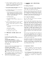
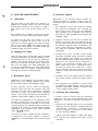
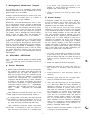
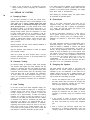
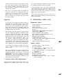
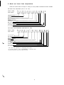
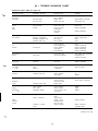
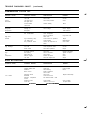
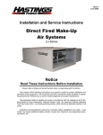
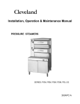
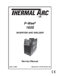
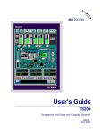
049
March, 1981
Supersedes
PE-G2
Dated Dec., 7975
PE-G3
Dated Oct., 1976
Westinghouse Electric Corporation
OPERATION MANUAL
Commercial-Industrial
Air Conditioning Division
Staunton, Virginia 24401
PE - 606310791160
Models PE 15OW 55OW
PE 063/079/100
Top Mounted
Compressor Units Only
Operation &
Maintenance
Manual
- COMPRESSOR NAMEPLATE
MAIN UNIT
NAMEPLATE
AND
SHOP ORDER NO
CONDENSER NAMEPLATE
EVAPORATOR NAMEPLATE
OPERATION
APPLICATION
Recycling Timer (TDR) -Set 40 minutes.
Limits number of starts per hour (3 starts in 2
hours).
The operation and maintenance procedures covered
in this publication apply to model PE (hermetic motor)
and PG (open motor drive) units of the compressor
sizes indicated throughout the literature. Open drive
units require additional operation and maintenance
inspections related to motor bearing lubrication coupling and shaft alignment. For coupling and shaft
alignment, see Bulletin PE-G10. For motor maintenance, see the instructions for service provided by the
motor manufacturer.
I.
Cycling Thermostat-C.T.
W ill stop machine when the leaving water
reaches its set point in normal operation.
Vane Closed Switch-V.C.
Prevents the machine from starting if the vanes
are not closed.
CONTROL CENTER
The control center is wired so that an indicating light
will be energized upon the action of any of the safety
controls. The light will remain on until such a time as
the control circuit is reset even though the cause of
compressor shutdown has been corrected or has
corrected itself. Repeated trippings of any safety
control should be investigated by a qualified refrigeration mechanic or Westinghouse service engineer. The
control reset buttons are located on the outside of the
control center. Discharge, suction and oil pressure
gauges are provided on the control center.
The control center contains all of the necessary
protective and operating controls, (less water flow
interlocks). These include the cycling thermostat, the
Guardistor protective circuit,SurgegardTM, high and
low pressure cutouts, oil pressure protector, oil temperature cutout, vane closed switch, low pressure
override, oil pump time delay, oil pump contactor,
oil pump overload, capacitor, recycling timer, indicator
lights and relays, motor load and temperature module.
The current design control center is subject to redesign
and modification. If the unit control center is different
than the one shown in Figure 2, see PE-G063/079/100
supplement.
An interior view of the control center is shown in Fig.
2.
B. Guardistor Protective Circuit
A. Controls
Positive protection against motor overheating is provided with this unique Westinghouse motor development. The heart of the Guardistor protective circuit are
the thermistors, embedded in the motor windings,
which sense motor temperature.
(For complete control summary, see Table 1.)
The function of operating controls is as follows:
Oil Pump Time Delay (OTD) -Set at 30 seconds
to keep oil pump running for 30 seconds after
machine has shut down.
When the motor temperatures are normal, the therm-
TABLE 1 - OPERATING CONTROL SUMMARY
CONTROL
SETTING
SYMBOL
HIGH PRESSURE CUTOUT*
LOW PRESSURE CUTOUT*
150 PSIG
26 PSIG
H. P.
L. P.
Stop machine on excessive head pressure
Stop machine on excessive drop in suction pressure.
FUNCTION
0. D.
Stop machine when oil pressure differential drops to 50 PSIG.
OIL PRESSURE SWITCH*
50 PSIG
LOW PRESSURE OVERRIDE
28-31 PSIG
OIL TEMPERATURE SWITCH”
14O’=F
0. T.
Stop machine when oil temperature entering machine exceeds setting.
23O’=F
30 PSIG
H. T.
v. c.
Stop machine on rise in discharge temperature
Will not allow machine to start if the vanes are not closed to minimum
DISCHARGE TEMPERATURE
VANE CLOSED SWITCH
SWITCH*
L. P. 0.
Closes vanes, on drop in suction pressure
OIL PUMP TIMER
3 Minutes
0. P. T.
RECYCLING TIMER
40 Minutes
T. D. R.
Limits number of starts of machine to 3 every 2 hours.
OIL PUMP TIME DELAY
30 Seconds
0. T. D.
Keeps oil pump running for set time after machine stops
CYCLING THERMOSTAT
Adjustable
3 6 F 9OF
C. T.
LOW OIL TEMPERATURE*
120° (Min.1
L. 0. T.
SYSTEM MONITOR TIMER
1 Minute
SURGEGARD RELAY”
_
Stops oil pump if machine fails to start.
Stop machine when chiller leaving water reaches temperature below
design condition
Prevents compressor from starting with low oil temperature
S.M.
Lights system monitor light if machine does not start due to external
interlocks or starter safeties.
S.G.R.
Lights Surgegard light and shuts down machine if surge condition
developes-check condenser water and tower condition.
*All safety switches that stop the machine require manual resetting before machine will restart
3
Figure 2
P
P
VANE SPEED
ADJUSTMEN
rOPEN
J
1.. Relay Base
2.
3.
4.
5.
6.
7.
8.
9.
10.
11.
O.P.T. Relay
Oil Pump Run Capacitor
Oil Pump Contactor
Transformer
Oil Pump Time Delay (OTD)
Anti Recycle Timer (TDR)
Relay115Volts(R1 thruR7)
Guardistor Relay
Solid State Module
Low Oil Temperature Cutout
istor has low resistance which remains nearly constant
up to predetermined critical temperature. At this
temperature, a sharp increase in resistance occurs for a
small increase in temperature. This sharp increase in
resistance causes the Guardistor relay to drop out
which in turn interrups the flow of current to the
Guardistor reset relay causing it to become deenergized. When the Guardistor reset relay contacts
open, t h e M C R r e l a y h o l d i n g c o i l b e c o m e s deenergized stopping the compressor.
A thermistor-equipped motor which utilizes the Guardistor protective circuit integrates all heat causing
factors of load, ambient, and power supply in the
motor windings to give you greatly increased protection against motor burnout.
The Guardistor control is a manual reset protective
12.
13.
14.
15.
16.
17.
18.
19.
20.
21.
22.
CL )SE
Oil Pressure Gauge
Discharge Pressure Gauge
Evaporator Pressure Gauge
Oil Pump Motor Overload
High Pressure Switch
Cycling Thermostat
Low Pressure Override
Surgegard Relay
High Oil Temperature Thermostat
Low Pressure Switch
System Monitor Timer
device. The reset button is provided on the control
center. THE CONTROL CIRCUIT MUST BE RESET
IN THE EVENT OF A POWER
FAILURE OR
WHENEVER THE CONTROL VOLTAGE SOURCE
IS INTERRUPTED.
C. SurgegardTM
Westinghouse currently uses a control device to sense
the occurance of a surge and stop the compressor
before any damage can be sustained.
The Surgegard relay will prevent the compressor from
restarting automatically until the malfunction can be
corrected. Possible causes for a surge, or rotating stall
condition, may be dirty condenser tubes, cooling
tower, pump, or control malfunction which acts to
elevate the system’s head.
D. Solid State Capacity Control
Figure 3
The Westinghouse solid state capacity control is
designed to provide the temperature control and
current limit control in a single solid state package with
a proportional type pulsing temperature control action.
The control is provided with indicator lights and a
quick disconnecting cable for replacement of the entire
module in case of malfunction of its internal circuits.
When the automatic temperature control is in operation, the vane control solenoids are energized intermittently at a frequency which increases in intensity as the
water temperature departs from the set point until a
full signal is maintained when the water temperature is
approximately 6OF or more away from the required
temperature. This action is designed to eliminate the
saw tooth operation of the conventional floating control and should provide extremely stable temperature
control when coupled with the needle valve vane
speed controls. The speed of the vane close operation
is approximately one minute from full open to full
close, and 3 to 5 minutes from full closed to full
open.
A selector switch provides the operator with means for
manual control in addition to the normal automatic
operation. Switch positions are:
Stop - this places the vanes in a stop position.
Load - this energizes the load solenoid, moving the
vanes to an open position.
Unload - this energizes the unload solenoid, moving the vanes to a close position.
Automatic - this provides for automatic operation
as described above.
sketch Fig. 3.
2. Metering Valves
The needle metering valves in the oil drain lines are
used to control the speed of vane travel while under
temperature control. The valves are factory-set so that
from a full close to full open position of the vanes
requires a minimum of 3 minutes. Maximum rate of
travel will be dictated by load requirements. To
decrease speed of travel, close the valve slightly.
Speed should be slow enough to prevent overcontrolling. At this rate of travel, the temperature can
be sensed and vanes stopped before a hunting
situation occurs. Vane speed can be adjusted through
access holes on the right hand side of the control
panel.
Indicator lights will function as follows: Red will light
during the unloading control action; green will light
during loading, and amber will light when the load
action is overridden by the current limit control. This
light will not light if the current limit acts while the
capacity control is in hold or unloading position.
Current limit will override manual control.
1. Vane Operation
The hydraulic system for the vane control operation
consists of a 4-way normally-open solenoid valve. The
action of this solenoid valve controls the operation and
position of the vanes. Oil under pressure is supplied to
either or both sides of the piston depending upon what
signal is being given by the electronic control.
E. Temperature Control
The temperature control has been calibrated at the
factory and should not need adjustment. Run the
unit for several hours and check the leaving water
temperature against customer requirements. If calibration is required, operate the system by hand and
obtain the proper condition.
To open vanes, solenoid “SA” is de-energized and
“SB” is energized allowing oil to flow from port C2 in
the solenoid valve to the piston and from the piston to
the drain through port Cl.
Because of the proportioning features of the temperature control, it will be necessary to have the
selector switch in the hold position for at least 5
minutes before calibration. (The thermal feedback
action will cause an apparent and temporary shift in
set point in the direction of the applied feedback or
control action. )
To close vanes, “SB” is de-energized and “SA” is
energized allowing the oil to flow from port Cl to the
piston and draining from port C2.
When the vanes are in hold position, both solenoid
coils are de-energized putting full oil pressure on both
sides of the piston through both Cl and C2 ports. See
5
3. Set the temperature selector knob at the actual
leaving water temperature. Switch the control to
automatic and immediately calibrate the temperature control until both lights are out. One or the
other of the lights will eventually begin to pulse
because the dead band is less than .5F. However,
the lights should never alternately pulse between
load and unload unless the vanes are moving too
fast.
leaving oil temperatures should be on the low side of
the acceptable temperature range when operating with
the coldest water. Long shutdown periods will produce
higher than normal chilled water temperatures at
startup and will result in higher oil temperatures until
the chilled water temperature is reduced.
Bearings are supplied with oil through internally drilled
passages. The oil drains from the bearings into the
gear housing and returns to the oil pump through the
scavenger line.
F. Current Limit
The oil pump also supplies the oil to the hydraulic
piston for positive positioning of the inlet guide vanes.
Proper operation of the hydraulic system and bearing
lube system can be maintained only if Westinghouse
recommended oil is used. Westinghouse recommended oils are 300 sus. viscosity (Suniso 4G or Texaco
WF68) for PE063 and PE079, and 500 sus. eviscosity
(Suniso 5G or Texaco WFIOO) for the PEIOO.
1. A 5.0 volt signal is required from the compressor
starter current transformer at full current. A 1 ohm
resistance will provide 5.0 volts from a 5 amp
transformer setting.
2. Set the current demand limit selector switch against
the stop 100% and the current limit calibration
screw fully counter-clockwise,
3. Start the system and place the selector switch in
load position. When the full load current reaches
customer requirements, turn the current limit calibration clockwise until the amber light comes on.
This places the control in current limit hold position
and insures that the unload action will be energized
if the current increases an additional 5%. Unload
the machine and reload to R.L.A. (Rated Load
Amperage) and check calibration.
a
II.
The quantity of oil charge for each machine is shown
in the Physical Data, Section Xl.
The oil pump is equipped with an externally adjustable
relief valve - This valve should be adjusted to
maintain 100-110 Ibs. net oil pressure (100/110 Ibs.
above suction pressure).
The heaters must remain on at all times the compressor is off. IN THE EVENT OF A POWER LOSS TO
HEATER ALLOWING OIL TO COOL, THE OIL
HEATER SHOULD BE ENERGIZED A MINIMUM OF
24 HOURS PRIOR TO THE TIME COMPRESSOR
IS STARTED. If the compressor has to start immediately, oil should be drained and system recharged with
fresh oil, which is free of refrigerant.
An alternate method of adjusting the motor load
control is by allowing the motor to load to some
amperage value below R. L.A.. Adjust the calibration screw clockwise until the amber (hold) light
comes on. At that point observe the amperage.
Proceed by slowly adjusting the calibration screw
counter-clockwise until the amber light goes out
and the green (load) light comes on. Allow the
machine to load until the amber light again comes
on. Again observe amperage. Continue this procedure until the full load amperage is reached. When
the 100% adjustment has been made, the 105% is
made simultaneously and no further adjustment is
required.
A low oil temperature thermostat in the control center
prevents starting the compressor with cold oil. This
thermostat should be set as high as ambient conditions
will allow. This is an automatic reset device and when
tripped, will cause the oil temperature light to glow.
There is also a heater in the gear case of the
compressor which maintains the proper heat in the
gear case during the off period to insure proper oil
return on start.
LUBRICATION SYSTEM
The oil pump is completely self-contained in its own
reservoir. The assembly includes the pump, pump
motor, oil heater and oil separator. The oil is pumped
through the oil discharge line, through a service valve
to the shell and tube oil cooler, then to the 5-micron oil
filter in the compressor casting. The cooler serves a
dual purpose. It lowers the temperature of oil on start
to prevent refrigerant flashing, and maintains proper oil
temperature under normal operating conditions. The
water flow through the oil cooler must be adjusted
with the balancing valve so that the temperature of oil
supplied to the compressor bearings (leaving the oil
cooler) is not less than 80°F nor more than 11O’F. On
systems using chilled water for a cooling medium,
The oil filter should be changed after the first month of
operation and annually thereafter.
Oil Safety
A spring-loaded piston and accumulator is incorporated within the compressor to provide oil pressure to
the bearings, during spin-down, in the event of the
loss of oil pressure.
6
Figure 4
1.
2.
3.
4.
5.
6.
7.
8.
III.
Oil Cooler Water Connection In
Oil Cooler Water Connection Out
Oil Cooler
Discharge Check Valve
Discharge Victaulic Coupling
Motor Cooling Line
Guardistor Terminal Junction Box
Motor Terminals
9..
10.
11.
12.
13.
14.
15.
16.
PRELIMINARY CHECKS
BEFORE STARTING
Motor Cooling Liquid Line Driers
Hot gas by-pass thermostat
Motor Cooling Liquid Line Shut Off Valve
Main Expansion Valves
Liquid Line Shut Off Valve
Condenser Pressure Relief Valves
Evaporator Pressure Relief Valve
Hot Gas Bypass Valve.
oil sump should be opened fully, the back valve
(closest to the unit going to the gear case) should
be open two turns from back seat.
Important
1. Open all water valves to the condenser and see
6. Manually operate the condenser water-regulating
valve (used on city water installations to clean the
water lines of sediment that accumulated during
installation. This will prevent the sediment from
damaging the seat of the water-regulation valve
when operating in an automatic position. When a
cooling tower is used, the HWR (condenser pump)
relay should be energized when the compressor
switch is “on”. Flush the tower and piping before
starting unit.
that water flow is possible when the water pumps
are energized.
2. Check that the actual line voltage is within the
allowable plus or minus 10% of nameplate rating.
3. With the main disconnect switch in the “off”
position, and the control circuit energized, make
sure all linestarter contacts meet with even pressure and that all moving parts move freely. Check
that the Fusetrons are in the circuit, that the
cycling thermostat contacts are open and that the
off-on switch is in the “off” position.
7. Check to make sure the compressor starter overloads are filled with dash pot fluid if this type
overload is used. See tag attached to overloads by
starter manufacturer for overload ratings. If starter
is Star Delta the overloads are rated on phase
amps. DO NOT ATTEMPT FIELD CALIBRATION
OF OVERLOADS.
4. Check that the liquid shutoff valves are open. The
(3) %” valves for discharge, suction, and oil
pressure must be opened.
5. See that the oil pump has a proper supply of oil.
The oil should be visible in the sight glass. OIL IN
THE SUMP SHOULD BE HOT- approximately
130F to 140F. Assure oil pump valves are open.
The front and the middle valves on the top of the
8. Check all pumps visually for proper rotation.
Check evaporator and condenser water flow switches for proper operation.
9. Check the power supply phase sequence.
7
10. Check all electrical connections to make sure they
are tight. Serious difficulty could result from loose
connections. It is recommended all electrical connections be retightened prior to startup.
V. STARTING AND OPERATIONAL
CHECKS
A. Starting Sequence
11. The oil cooler solenoid (SF) should energize at the
When the 115 volt AC power supply is applied to the
control panel for the fist time or after an interruption in
control voltage, the following will take place:
same time the oil pump is energized.
12. If all indicator lights are out and oil pumps fails to
start, check the following:
Both the oil sump heater and gear case heater will be
energized. With the compressor switch in an off position, no lights will be lit. When the switch is placed in
the “on” position, the oil pressure light will light. By
depressing the reset button the lights will go out, and
if an alarm circuit is used it too will be de-energized.
a. Recycling time (set at 40 minutes limit start per
hour). CAUTION: Severe damage to the compressor can result if the anti recycle timer is
turned to the Off position and the water flow
interlocks operate intermittently.
b. Interlocking devices
C.
B. To Start The Machine
Oil pump-overload tripped.
Start the chilled water pump. Place the compressor
switch in the “on” position.
d. Defective oil pump contactor, holding coil or
contacts.
W ith the system water temperature higher than the
setting of the cycling thermostat, the condenser water
pump starts. This closes the interlock circuit and
allows the oil pump to start and energize oil cooler
water solenoid valve. When the oil pump develops the
pressure required to close the oil differential switch (50
Ibs. above suction pressure), it will close. If the vane
closed switch is closed, it will energize the motor
control relay in the starter (MCR), and relay “R3”. The
machine will start. The vanes will be controlled by
either the electronic motor control (motor amps) or the
electronic temperature control (chilled water temperature).
13. If all the indicator lights are out, the oil pump
starts and the MCR relay fails to energize, check:
a. Vane closed switch (must be in closed
position).
b. Oil pressure (must have minimum 50 PSIG
differential).
c. Main starter overloads.
d. Condenser pump interlock.
e. Starter/control interlock wiring
IV. PRESTART SYSTEM CHECK LIST
When and if the load drops below the minimum the
unit can handle (approximately 10% of full load) the
leaving water temperature will drop to the setting of
the cycling thermostat and will open, stopping the
machine. The oil pump will continue to run for 30
seconds after the machine stops.
A. Unit
All service valves in operating position
Control circuit energized and oil heaters operating for
24 hours
Oil charge visible in sight glass
All safety switches interrupt M.C.R. operation
Oil cooler water balance adjusted to approximate flow,
Proper flow through condenser and chiller. See A.D.
100-20 8 A.D. 100-21 for water flow curves.
The machine can restart upon closing of the cycling
thermostat if the previous “on” cycle was greater than
40 minutes. If the previous “on” cycle was less than 40
minutes, it will be necessary for the remainder of the
40 minutes to elapse before the machine can restart.
This is determined by the T.D.R.
B. Electrical
C. Operational Checks
Proper wire, breaker sizes and phase sequence (l-2-3)
All wiring done as per Westinghouse diagram
All interlocks operating properly
All pumps rotating in proper direction and lubricated
All electrical connections tight
All starter parts move freely and contacts meet evenly
Motor overloads properly sized and filled with Dashpot
fluid
All load equipment operative and lubricated (fan coil
units, environmental equipment, process equipment)
Recycling timer set to 40 minutesTower fan and controls operative (if applicable).
1. Check the compressor and oil pump motor amperage to make sure they are not in excess of
nameplate rating. The correct amperages are given
on the nameplates.
2. All accessories and controls should function according to requirements. If the performance of any
accessories or any operational function appear
abnormal, stop compressor and investigate the
malfunction.
8
3. Check the operation of all the protective control to
make certain that each interrupts the control circuit.
The correct settings for the controls are given in
Table 1. Check the controls as follows:
4. Several causes for frequent complaints are listed
below:
a. High Pressure Cutout-Throttle the condenser
water supply slowly until reaching the cutout
point. Stop the compressor manually if the discharge pressure exceeds the correct cutout
setting. Unit must be operating at 70% to 100%
capacity to prevent a surge condition.
b. Inadequate quantity of water (check pressure
drop through chiller and condenser). See AD
100-20 and AD 100-21 for vessel pressure drops.
a. Air in water circuit or vessel
C.
Water pump not functioning properly
d. Plugged water strainer
b. Low Pressure Switch--Low Pressure OverrideBoth switches can be checked simultanously by
isolating the line going to the suction of the
control panel. Close the 3-way valve located on
the top of the evaporator to the right of the control panel. Slowly bleed pressure off the line
going to the control panel. Observe gauge pressure to determine trip point of the low pressure
cutout. Low pressure override operation can be
checked using a voltmeter or ohmmeter at the
terminals. LPO should close the vanes when
suction pressure drops below 32 to 28 psig.
e. Lack of head pressure control
f. O p e r a t i o n a t
temperature
lower
than
design
water
g. Inadequate air over cooling coils
h. Lack of low side load-operating with only a
portion of air units installed or operating.
5. Record complete set of operating data for future
usage.
c. Oil
Pressure
Protector- Manually Close
the differential pressure switch by holding
the spring toward the front of the control.
6. Instruct the owner on proper operation and care of
the system.
d. Cycling Thermostat-Place a thermometer in the
outlet water of the chiller, the control can be
checked by slowly throttling the supply water to
the chiller. This will cause the outlet water temperature to drop. The reduction in water flow
must be done slowly enough for the thermometer to react to the temperature change. If
a thermometer is not available in the outlet
water, the control can be checked by placing the
control bulb in a container of water; by slowly
adding ice to the water, the operating point of
the control can be reached. Observe temperature on thermometer.
CAUTION: The disconnect switch for control circuit (furnished by contractors) must be left on at all
times in order to maintain operation of the oil and
compressor heaters. The control center selector
switch can be turned to the “off” position at such
times that compressor operation is not desired.
D. Shutdown
The sequence in a normal shutdown is as follows.
Upon placing the compressor switch in the “off”
position, the condenser pump relay is de-energized,
and the MCR relay drops out. The compressor and oil
pump heaters come on and the oil pump continues to
run for 30 seconds, after the machine has stopped, at
w h i c h t i m e t h e o i l c o o l e r s o l e n o i d (S.F.) is deenergized.
e. High Oil Temperature Control-To check the
operation, immerse sensing bulb in 150°F water.
This should stop the compressor.
f. Check setting on recycling timer. It is set at 40
minutes to limit compressor to 3 starts every two
hours.
g. Overloads are calibrated and set by the starter
manufacturer to trip at 105% of compressor
nameplate full load amperage.
If the unit is stopped by a safety, the sequence is the
same as a normal shutdown plus the appropriate
indicator light becomes energized. The machine will
stop and remain off until the reset is pushed, even if
the cause of the outage has corrected itself.
h. Vane-Closed Switch-This switch is only functional until the machine starts. Before the machine starts, manually open the switch. After the
oil pressure switch has closed, the machine will
remain off until the vane closed switch, which is
manually held open, is closed.
When the machine is stopped by a current interruption
or the tripping of the oil pump overload, oil (from
accumulator) will be supplied to the bearings for the
spin-down period by the action of a spring-loaded
piston which forces oil through the oil passages. Thus,
the machine has oil pressure on all shutdowns, even if
there has been a power failure.
i. See that the oil pressure protector is set to
approximately 50 PSIG differential.
9
MAINTENANCE
VI. ROUTINE MAINTENANCE
D. Electrical System
A. Lubrication
Maintenance of the electrical system involves the
general requirement of keeping contacts clean and
connections tight and checking on specific items as
follows:
After the system is once placed into operation, no
additional oil is required except in the event that repair
work becomes necessary to the oil pump or unless a
large amount of oil is lost from the system due to a
leak.
1. The compressor current draw should be checked
and compared to nameplate value. Normally the
actual current will be lower since the nameplate
rating represents full load operation. Also check all
pump and fan motor amperages and compare with
nameplate ratings.
The oil system can be isolated to service any oil pump
component or IGV (inlet guide vanes) solenoid system.
To isolate the inlet guide vane system,
necessary to backseat the service valve
pump (the one with the XI” line) and close
valve (on the oil filter). Relieve the pressure
the inlet guide vane solenoids, oil pressure
oil pressure gauge can then be serviced.
it is only
on the oil
the supply
slowly; and
switch and
2. Inspection should verify that the oil heaters are
operative. The heaters are insert cartridge type and
can be checked by ammeter reading. They should
be energized whenever power is available to the
control circuit (whenever compressor is inoperative). When the compressor starts the heaters are
de-energized.
B. Changing Oil Filters
Close the supply valve on the oil filter cavity on CEO79
and CE100 compressors. On CEO63 compressors, close
the discharge valve on the oil pump pot. Relieve the
pressure on the oil filter housing line by purging slowly.
When all the pressure has been vented, remove the
filter cover and replace core. When reassembling, vent
as much air as possible from the oil lines before placing
the machine back into operation. Westinghouse recommends the oil filter be changed annually.
3. At lease once a year, all safety controls except
compressor overloads should be made to operate
and their operating point checked. Any control may
shift its operating point as it ages, and this must be
detected so the controls can be readjusted or
replaced. The compressor overload relays are a
safety control, but to force a compressor load to
trip them may cause more trouble than it saves.
Purnp interlocks and flow switches should be
checked to assure the interrupt control circuit when
tripped.
C. Refrigerant Cycle
4
Maintenance of the refrigerant cycle consists of maintaining a log of the operating conditions, and assuring
the unit has the proper oil and refrigerant charge.
Contactors in the motor starter should be inspected
and cleaned annually. Tighten all terminal connections.
5. The compressor motor resistance to ground should
be checked and logged annually. This log will track
insulation deterioration. Reading of 500,000 ohms
or less indicate insulation failure.
At every inspection, the oil, suction and discharge
pressures should be noted and recorded, along with
condenser and chiller water temperatures. Assuming
water flow is correct, this confirms correct refrigerant
charge. Correct suction pressure will be indicated by
reference to past suction readings on the same unit.
F . Cleaning and Preserving
E.
A common cause of service calls and equipment
malfunction is dirt. This can be prevented with a little
maintenance. The system components most subject to
dirt are:
The suction line temperature at the compressor should
be taken at least once a year. Subtracting from this,
the saturated temperature equivalent of the suction
pressure will give the superheat. Extreme changes in
superheat over a period of time will indicate possible
deterioration of the expansion valves. Proper superheat
setting is 2-6OF at full load.
Permanent or cleanable filters on the air handling
equipment must be washed in accordance with the
throwaway filters
manufacturer’s instructions;
should be replaced. The frequency of this service
will vary with each installation.
The factory oil charge, supplied with the compressor,
is adequate for the system. Normal oil charge is
indicated by an oil level visible in the oil reservoir sight
glass.
Remove and clean strainers in chilled water pump,
oil cooler line and condenser water pump at every
inspection.
10
to oil heater. Set compressor switch to “off”
position. To insure against the possibility of an
accidental start, remove relay Rl.
F. Westinghouse Maintenance Program
It is necessary that an air conditioning system receive
adequate maintenance if the full equipment life and full
system benefits are to be realized,
5. Check for corrosion and clean and paint rusted
surfaces.
Followup Inspection-Maintenance should begin with
an inspection of the system after 3 to 4 weeks of
normal operation on a new installation.
B. Annual Startup
A dangerous condition can exist if power is applied to
a faulty compressor motor stator which has been
burned out. This condition can exist without the
knowledge of the man starting the equipment.
This is a good time to check the motor winding
resistance to ground. Annual checking and recording
of this resistance will provide a record of any deterioration of the winding insulation. All new units have well
over 100 megohms resistance between any motor
terminal and ground. Whenever great discrepancies in
readings occur or uniform readings of less than 5
megohms are obtained, the motor cover should be
removed for inspection of the winding prior to starting
the unit. Uniform readings of less than 5 megohms
indicate motor failure is imminent and motor should be
replaced or repaired. Repair before failure occurs can
save a great deal of time and labor expanded in the
cleanup of a system after a motor burnout.
Maintenance Contracts-Westinghouse offers a variety of maintenance services through its Nationwide
Service Organization. These contract services include
regular inspections and emergency service by factory
trained technicians. These services are available
around the clock to keep your equipment running in
top condition. With a Westinghouse Assured Maintenance contract, all parts, labor and materials are
furnished .with no additional cost to the customer.
It is widely recognized that a good maintenance
program is the essential first step in controlling energy
costs. And through the Westinghouse Assured Maintenance and Energy Management Program (W.A.M./
E.M.) the owner is assisted in establishing a comprehensive Energy Management plan to meet his needs.
For further information concerning the many services
available, contact your local Westinghouse Service
Representative.
1. The control circuit should be energized at all times.
If the control circuit has been off and oil is cool,
drain and replace with fresh oil or allow 24 hours for
heater to remove refrigerant from the oil before
starting.
VII. SEASONAL SERVICING
Prior to seasonal shutdown periods and before starting
again, the following service procedures should be
completed.
2. Check and tighten all electrical connections.
A. Annual Shutdown
3. Replace the drain plug in cooling tower pump if it
was removed at shutdown time the previous
season.
Where freezing temperatures may be encountered,
the condenser and chiller water piping should be
disconnected from the supply and drained of all
water. Dry air blown through the condenser will aid
in forcing all water out. Removal of condenser
heads is also recommended. The condenser and
evaporator are not self-draining. Water permitted
to remain in the piping and vessels will rupture
these parts if subjected to freezing temperatures.
FORCED CIRCULATION OF
ANTIFREEZE
THROUGH THE WATER CIRCUITS IS THE
ONLY
SURE
METHOD OF AVOIDING
TROUBLE.
4. Install Fusetrons in main disconnect switch (if
removed).
5. Reconnect water lines and turn on supply water.
Flush out condenser and check for leaks.
6. Clean and flush water tower for all units operating
on a water tower. Make sure tower “blowdown” or
bleedoff is operating. Set up and use a good
maintenance program to prevent “liming up” of
both tower and condenser. It should be recognized
that atmospheric air contains many contaminants
which increases the need for proper water treatment. The use of untreated water may result in
corrosion, erosion, sliming, scaling or alge formation. It is recommended the service of a reliable
water treatment firm be obtained to determine
what, if any, treatment is required-Westinghouse
assumes no responsibility for the results of untreated or improperly treated water.
Take measures to prevent the shutoff valve in the
water supply line from being accidently turned on.
If a cooling tower is used and if the water pump will
be exposed to freezing temperatures, be sure to
remove the pump drain plug and leave it out so that
any water which may accumulate will drain away.
Open compressor disconnect switch, and remove
Fusetrons. If transformer is used for control voltage, disconnect must remain on to provide power
7. Clean all surfaces and remove all litter. A clean unit
is the sign of an good serviceman.
11
If any leaks are found in welded or silver soldered joints
or if it is necessary to replace a gasket, relieve the test
pressure in the system before proceeding. For copper
joints, silver solder is recommended.
8. Refer to the procedures of “Preliminary Checks
Before Starting” before energizing the compressor
circuit.
VIII. REPAIR OF SYSTEM
After making any necessary repair, the system should
be evacuated as described below.
A. Pumping Down
D. Evacuation
If it becomes necessary to pump the system down,
extreme care should be used to avoid damage to the
water chiller due to freezing. Always make sure that
full water flow is maintained through the chiller
while pumping down. To pump system down, close
all liquid line valves (1 to the motor cooling line, 1 t o
the chiller). With all liquid line valves closed and water
flowing through chiller, start the compressor. In order
to pump system down as far as possible, it will be
necessary to by-pass the low pressure override switch
and jumper the Low Pressure cuttout. Set temperature
module to manual load position. Vanes must be open
while pumping down to avoid a surge or other damaging condition.
After it has been determined that there are no
refrigerant leaks, the system should be evacuated
using a vacuum pump with a capacity of approximately
3 cu. ft/min. and that will reduce the vacuum to at
least 1 millimeter (1000 microns).
A mercury manometer, electronic or other type of
micron gauge should be connected at the farthest
point from the vacuum pump. For readings below 1
millimeter, the electronic or other micron gauge should
be used.
The triple evacuation method is recommended and is
particularly helpful if the vacuum pump is unable to
obtain the desired 1 millimeter of vacuum. The system
if first evacuated to approximately 29 inches of
mercury. Enough refrigerant vapor is then added to the
system to bring the pressure up to zero pounds. Then
the system is once again evacuated to approximately
29 inches of mercury. This is repeated 3 times. The
first pull down will remove about 90% of the noncondensables, the second about 90% of that remaining from the first pull down and after the third,
only 1/ 10 of 1% non condensibles will remain.
Operate machine until the suction pressure stabilizes at
approximately 20-25 PSIG.
Stop the machine. Allow pressure to build up. Repeat
this procedure 3 times.
After the system has been pumped down, the gas
pressure remaining will have to be purged before the
machine can be serviced.
B. Pressure Testing
E. Charging the System
No pressure testing is necessary unless some damage
was incurred. After repairs are made, pressure test the
system at a pressure that does not exceed the standby
pressure in the condenser. (A test pressure higher than
condenser pressure would open the discharge check
valve and allow flow of test pressure into condenser).
In cases where the entire refrigerant charge is lost,
follow the recommendations in the following paragraphs. The evacuation procedure can be followed in
both cases.
PE water chillers are leak tested at the factory and
shipped with the correct charge of refrigerant-12 as
indicated on the unit nameplate. In the event the refrigerant charge was lost due to shipping damage, the
system should be charged as follows after first repairing any leaks and evacuating the system.
1. Connect the refrigerant drum to the gauge port on
the liquid shutoff valve and purge the charging line
between the refrigerant cylinder and the valve.
Then open the valve to the mid position.
C. Leak Testing
In the case of loss of the entire refrigerant charge, the
unit should be checked for leaks prior to charging the
complete system. This can be done by charging only
enough refrigerant into the system to build the
pressure up to approximately 10 PSIG and adding
sufficient dry nitrogen to bring the pressure up to a
maximum of 125 PSIG and then leak test with a Halide
or electronic leak detector. CAUTION: DO NOT USE
OXYGEN TO BUILD UP PRESSURE AS A
SERIOUS EXPLOSION CAN RESULT. A Pressureregulating valve should always be used on the drum
being used to build up the system pressure. Also, do
not exceed the test pressure given above. When the
test pressure is reached, disconnect the gas cylinder.
2. Turn on both the cooling tower water pump and
chilled water pump and allow water to circulate
through the condenser and the chiller. (It will be
necessary to manually close the condenser pump
starter).
3. If the system is under a vacuum, stand the
refrigerant drum with the connection up and open
the drum and break the vacuum with refrigerant
gas.
4. W ith a system gas pressure higher than the
equivalent of a freezing temperature, invert the
charging cylinder and elevate the drum above the
13
one of the relief valves is leaking on the two valve set,
the following procedures should be followed:
condenser. With the drum in this position, valves
open, water pumps operating, liquid refrigerant will
flow into the condenser. Approximately 75% of the
total requirement estimated for the unit can be
charged in this manner.
If the valve closest to the valve stem is leaking, back
seat the three-way valve all the way, closing the port
to the leaking pressure relief valve. Remove and replace the faulty relief valve. Reopen the three-way
shutoff valve to the mid position.
5. After 75% of the required charge has entered the
condenser, reconnect the refrigerant drum and
charging line to the service valve on the chiller.
Again, purge the connecting line, stand the drum
with the connection up and place the service valve
in the open position.
If the relief valve furthest from the valve stem is
leaking, front seat the three-way valve and replace the
valve as stated above.
IX. OPERATIONAL CHECK LISTS
Important
Operational Check
At this point, the charging procedure should be
interrrupted and all prestart checks made before
attempting to complete refrigerant charge. Compressor must not be started at this time. (Preliminary check must first be completed). When all
prestart checks have been made, remaining steps in
charging procedure can be made.
Suction, discharge and oil pressure normal.
Proper superheat.
Proper sub-cooling.
Cutout points of all safety controls.
Oil level.
Oil temperature (90°Fm1 lOoF entering bearings).
Voltage within tI 10%.
Proper amperage for load conditions.
Vane operation, manual &thermostatic control.
Motor control 50% 100%.
Interlocks interrupt operation.
Recycling timer setting (40 min.).
Cycling thermostat setting. (3-5’ below leaving
chilled water temp. )
Check overloads (nameplate rating only).
6. After machine has been jogged and proper rotation
has been established make sure refrigerant shutoff
valves are open and that water is still circulating
through the chiller and condenser. Start the compressor by first closing the disconnect switch and
then place the control center selector switch in the
“on” position, checking that (a) oil pump starts
immediately and voltage and amperage are normal,
(b) compressor motor voltage and amperage are
normal and (c) that suction pressure and leaving
water temperatures are above freezing temperature.
System Checks
7. To complete the refrigerant charge, allow refrigerant to enter the system through the charging
valve on chiller.
All motors checked - amps and volts.
All pumps lubricated.
All strainers cleaned - condenser pump, evaporator pump and oil cooler.
All fans checked and filters on air handlers clean (if
applicable).
All condensate drains clean.
All motors lubricated.
All belts adjusted and checked.
All electrical connections tight, starter contacts,
starter movement.
Both the temperature and pressure readings must
be taken at full load conditions. Charge can be
checked by measuring the sub-cooling. It should be
9OF to ll°F on units with a lOoFAT a c r o s s t h e
condenser. On units with larger A’s, the subcooling
should be increased accordingly. Superheat at full
load should be 2 to 4 degrees F.
F. Pressure Relief Valve Replacement
Current condenser design uses two relief valves (1 set)
separated by a three-way shutoff valve. In the event
13
X. Model and Vessel Code Interpretations
Model and Vessel Codes are subject to change, as more possible combinations become available.
Old Model Code Interpretation (Prior to Jan. 1981)
Model number
Digit number
PEO63KAQ2ORFO2GA2
9 10 11 12 1
1 2 3 4 5 6 7
8
15 16 7
-rIl-l---IT
Evaporator Size Code*
Tube Type**
No. of Passes
Condenser Size Code”
Tube Type””
No. of Passes
I
New Model Code Interpretation (Used after Jan. 1981)
Model number
Digit number
PE063JA
1234561
T-T-
H 2
8 9
OFEFOZEEAZ
10 11 12 13 14
Type Compressor #Unit Size
Gear Ratio
WrT
Voltage
Evaporator Size Code’,
Tube Type**
No. of Passes
Condenser Size Code*
Tube Type””
No. of Passes
*See Vessel Code Interpretation for corresponding model number
“““A” Type-High Efficiency Tube, “0” Type-Smooth I.D. Conventional Tube.
#PE Units are Hermetic; PG Units are open motor drive.
14
I
XII - TROUBLE DIAGNOSIS CHART
Compressor Won’t Start No Lights Lit
POSSIBLE CAUSE
POSSIBLE
Grounded
Compressor
Fuse Blown
REASON
Wiring
Grounded Motor
Fuse Too Small
VERIFICATION
REMEDY
Check Connections
Check Insulation
Megger Motor
Refer to Elec. Data
Repair or Replace
Replace Stator if Necessary
Install Proper Size
Check Circuit
Refer to Elec. Data
Check -Electrical
ComponentsTransformer
Contactor
Repair
Resize Fuse
Replace if Necessary
Fouled Evaporator Tubes
Shortage of Refrigerant
Restricted Refrigerant Flow
Restricted Water Flow
Low Temperature Differential
Check for Leaks
Check Filter
Check Strainer
Clean
Repair Leak-Add Ref.
Clean
Clean
Oil
Pressure
Oil Pump Off
Check
Check
Check
Check
Check
Reset
Replace
Replace
Replace
Replace
Vane Closed
Switch
Vanes Open
Run Oil Pump And
Check Vane Operation
Flush Needle Valve if Necessary
Disassemble IGV
Assembly and Check
Compressor Time
Delay (TDR)
Bad Contacts on Relay
Bad Relay
Check Continuity
Check Coil
Replace if Necessary
Replace if Necessary
Oil Pump
Time Delay
(OTD)
instantaneous Contacts
Open
Bad Coil
Check Continuity
& Resistance
Replace or Repair
Compressor
Interlocks
Chilled Water Pump Off
Condenser Pump Off
Check Starter Coil
Check Overloads
Check Fuses
Repair
Or
Replace
Check Capacitor
Check Continuity
One Direction Only
200-900 Ohms
Replace
Check Internal Connections
Open Contacts
Set To High
Discharged Element
Check Continuity
Observe Setting
Adj. From High to Low
If Still Open
Replace
Adjust
Replace
Current Limiter Module
See Electronic Control Check
Page 7
Check Output
Voltage at 100%
Capacity Should
Be 4.5 5.5 Volts
Megger Windings
Repair or Replace
Control
Fuse
Blown
Low Pressure
Guardistor
Circuit
Cycling
Thermostat
(CT)
Grounded
Fuse Too Small
Shorted
Guardistor Circuit Open
Current Transformer
Starter
Overload
Tripped
Grounded or Shorted
Motor
Overloads
Voltage Relay
Capacitors
Motor
Bearings
Replace if Necessan/
if Necessary
if Necessary
if Necessary
if Necessary
Repair or Replace
Repair Connections
Or Replace Stator
-Continued Next Page
16
TROUBLE DIAGNOSIS CHART - (continued)
COMPRESSORS CYCLES OFF
POSSIBLE
CAUSE
POSSIBLE
REASON
VERIFICATION
REMEDY
Low Load
Check Load
Correct
Cycling
Low Water Flow
Check Pump Strainer
Clean
Thermostat
Set Higher Than
Observe Setting
Reset
Check Charge
Check- Repair
Control Module
Thermostat
Refrigerant
Shortage Of
Temperature
Refrigerant
Leaks Add Gas
Little
Non Condensables
Temperature
Rise on Condenser
High Head
Purge Non Cond.
Water Flow
Pressure
High Condensing Temp.
Check Tower Fan Operation
Repair
Low Water Flow
Check Strainer
Clean Strainer
Little Or No Temp Rise On
Clean Tubes
Dirty Condenser Tubes
Water
High Discharge
High
Oil
Temperature
Low Load
Vanes Closed
Load Compressor Check
Check Vane Operation
Correct
Repair
Oil Cooler Solenoid
Not Openrng
Hand Valve Off
Strainer Plugged
Low Flow
Check Coil
Check Connection:.
Check Valve
Remove Et Inspect
Check For Proper Flow
Replace if Necessary
Tighten Or Repair
Open
Clean
Adjust
POSSIBLE
VERIFICATION
REMEDY
RUNS NOTCOOLING
POSSIBLE
CAUSE
REASON
Low Oil Pressure
Plugged Needle Valve
Electronic
Motor Control
I.G.V. Closed
Check
Open W i d e
Check Setting
Refer To Electronic
Check Chart
Check Coils
Check Connection
See Electronic Check
Solenoids Closed
SA & SB
Electronic Temperature
Control
Solenoid Control
Circuit Off
-___
Flush Et Adjust
Reset
Replace If Neccessary
Chart
Check Starter
Interlock Connections
_-___ -____
17
Clean Contacts
Or Repair Wires
WESTINGHOUSE CENTRIFUGAL OPERATORS LOG
The weekly maintenance of a log is highly recommended by Westinghouse Corporation for the following reasons.
1.
. It provides an itemized checklist of critical system components.
2. It provides a systematic record that wiil allow you to identify trends that may be leading to future component
failure.
3. This log and the following information is sufficient for factory computer analysis of your chiller’s performance.
(a)Capacity control current settinq-%
(b)Water temperature set point _
(c)Temperature setting of cycling thermostat ~
Definitions of column headings:
Condenser and chiller water pressure drops: from inlet and outlet gauges in psi or differential pressure gauge in
inches of mercury or feet of water. (1 psi = .4911 in. - Hg. = 2.307 ft H,O = .3416 kg/CM* = 6.9 Kilopascal
Compressor Amps: The greatest amperage of the three lines should be recorded.
Suction Superheat = Suction Line Temperature - Measured Liquid Line Temperature
Condenser Subcooling = Saturated Condenser Refrigerant Temperature Measured Liquid Line Temperature
NOTE: Liquid line temperature should be measured on line between condenser and service valve
Oil temperature leaving cooler: This temperature should be measured mid-way between cooler and oil filter housing. During normal running it
should be maintained between 80” and 1 lOoF.
Job number is the Westinghouse shop order number found on the main nameplate.
PE/PF/PH, etc., followed by 4 digits. This number is
important anytime you need to contact the factory.
Full Load Design Conditions are listed on the Westinghouse shop order. If these have not been supplied by the contractor or engineer, they are
available from Westinghouse CIACD, P.O. Box 2510, Staunton, Virginia 24401, U S.A.
‘ F A H R E N H E I T = OF = ‘C x 915 + 32
’ CELSIUS = OC = loF -3215/g
Extra copies of the Operators Log Sheet may be obtained by ordering from the factory. Log sheets will be supplied in tablet form
designated by part number Cl-344.
18