1
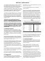
DFLIOM-2R
PN# 94.2000.01
P
4830 TRANSPORT DRIVE, DALLAS,TX 75247
PHONE: 214-638-6010 FAX: 214-905-0806 www.mestek.com
INSTALLATION, OPERATION AND MAINTENANCE MANUAL FOR
DFL MODEL DIRECT GAS-FIRED HEATERS
ATTENTION: READ THIS MANUAL AND ALL LABELS ATTACHED TO THE UNIT CAREFULLY
BEFORE ATTEMPTING TO INSTALL, OPERATE OR SERVICE THIS UNIT! CHECK UNIT RATING
PLATE FOR TYPE OF GAS AND ELECTRICAL SPECIFICATIONS AND MAKE CERTAIN THAT THESE
AGREE WITH THOSE AT POINT OF INSTALLATION. RETAIN FOR FUTURE REFERENCE.
FOR YOUR SAFETY
The use and storage of gasoline or other flammable vapors and liquids in open containers
in the vicinity of this appliance is hazardous.
FOR YOUR SAFETY
If you smell gas:
1. Open Windows
2. Don’t touch electrical switches.
3. Extinguish any open flame.
4. Immediately call your gas supplier.
c
WARNING: Improper installation, adjustment, alteration, service or maintenance can cause
property damage, injury or death. Read the installation, operating and maintenance
instructions thoroughly before installing or servicing this equipment.
WARNING: Install, operate and maintain unit in accordance with manufacturer’s
instructions to avoid exposure to fuel substances or substances for incomplete combustion
which can cause death or serious illness. The state of California has determined that these
substances may cause cancer, birth defects, or other reproductive harm.
lINSTALLER’S RESPONSIBILITY
Installer Please Note: This equipment has been test fired and inspected. It has been shipped free
from defects from our factory. However, during shipment and installation, problems such as loose
wires, leaks or loose fasteners may occur. It is the installer’s responsibility to inspect and
correct any problems that may be found.
POST AND MAINTAIN THESE INSTRUCTIONS IN LEGIBLE CONDITION
SECTION I - FORWARD
I.As is the case with any fine piece of equipment, care must
be taken to provide the proper attention to the operation
and maintenance details of this machine.
Table Of Contents
Section I: Forward and Table of Contents........................ 2
Section II: General Information........................................... 2
Section III: Installation............................................................ 3
Section IV: Pre Start-Up........................................................ 5
Section V: Unit Start-Up........................................................ 5
Section VI: Unit Shut Down.................................................. 6
Section VII: Troubleshooting Guide..................................... 7
Section VIII: Maintenance Schedule and
Lubrication Requirements............................ 13
Section IX: Maxon NP-I Airflo® Burners........................ 16
Section X: Maxitrol Valve Adjustments and
Preliminary Circuit Analysis............................17
Section XI: Replacement Parts........................................... 19
Section XII: Recirculation.................................................... 20
This manual of instructions has been prepared in order for
you to become well-acquainted with those details, and in
doing so, you will be able to give your Direct Gas-Fired
System the care and attention which any piece of
equipment needs and deserves.
SECTION II - GENERAL INFORMATION
A. Purpose
The purpose of this manual is to present a guide for proper
installation, maintenance, and operation of the Direct GasFired System, and supplement, but not to replace, the
services of qualified field service personnel to supervise the
initial start-up and adjustment of the unit. Persons without
previous experience with commercial and industrial heating
equipment should not attempt the initial adjustment and
checkout procedure which is essential before such
installations may be considered ready for operation. This
manual should be made readily available to all operating
personnel as an aid in troubleshooting and proper
maintenance.
All Direct Gas-Fired units are given a minimum 140 point
operations test and control circuit checkout before shipment. Copies of the wiring diagram, piping diagram and bill
of material are included with each unit shipped.
If correspondence with the factory is necessary, please
provide the unit model and serial number.
C. Optional Factory Service
Periodic service on any piece of mechanical equipment
is necessary for efficient operation. A nationwide service
support network is available to provide quick and dependable
servicing of make-up air, heating, ventilating, or air handling
types of equipment. The factory also offers start-up service
which includes the presence of a service engineer to
supervise the initial start-up and adjustment of the equipment
and provide instructions for the owner’s maintenance
personnel on proper operations and maintenance. Consult
factory for quotations on periodic or start-up service.
B. Shipping
Direct Gas-Fired units are shipped completely assembled
where shipping limitations allow. Optional inlet hoods
or other large accessories are assembled and shipped
mounted and wired whenever possible within limitations of
shipping and handling. Any optional accessories shipped
separately are shipped as assembled sections.
Shipments are made F.O.B. Dallas,Texas by flatbed truck
or LTL shipment. The unit is securely strapped, tied, and
blocked to prevent shipping damage. All shipments are
checked by an inspector before they are accepted by the
carrier. Parts that are shipped unmounted are noted
on the bill of lading. These parts, where feasible, are
packaged and shipped with the units. Upon receipt of
shipment, all units should be checked against the bill of
lading to insure all items have been received. All equipment
(and any optional accessories) should be checked carefully
for physical damage in the presence of the carrier’s
representative. If parts are missing or damage has occurred,
a claim should be filed immediately with the carrier.
2
SECTION III - INSTALLATION
This equipment must be installed and wired in accordance
with regulations of the National Board of Fire Underwriters, National Electrical Code, and local governing bodies.
The following recommendations are not intended to
supplant any requirements of federal, state, or local codes
having jurisdiction. Authorities having jurisdiction should be
consulted before installations are made. Local codes may
require additional safety controls and/or interlocks.
Recirculation of room air is not permitted. All air must be
ducted from the outdoors.
If in doubt regarding the application of this appliance,
consult the factory.
Locate the unit exactly level. Special attention should be
given to the duct, electrical, and fuel connection points.
Install duct work with adequate flexible connections to
isolate vibrations from the duct work. All duct work should
have taped or caulked seams. Duct work should be
properly sized so as not to inhibit airflow. This information
should be cross-checked with the position of support
beams and stand pipes to insure that clearance dimensions
coincide with those of the unit. The minimum clearance to
combustible material must be maintained as listed in Table 1.
All installations in airplane hangers must be in accordance
with current ANSI/NFPA No. 409. All installations in public
garages must be in accordance with the current Standard
for Parking Garages, NFPA No. 88A, or the Standard for
Repair Garages, NFPA No. 88B, and with CAN/CGA B149
Installation Codes.
CAUTION: Do not install heating system in
corrosive or flammable atmospheres! Premature
failure of, or severe damage to the unit will result!
Table 1
Minimum clearance to combustible material and access
clearance (consult local codes and regulations)
Clearances to Combustible Material
Vertical Units
Horizontal Units
Front*
36 inches
36 inches
Rear
6 inches
6 inches
Right
6 inches
6 inches
Left
6 inches
6 inches
Top
12 inches
12 inches
Floor
Zero
6 inches
* Consider control side as front of unit.
CAUTION: Heating system must not be installed
in locations where air for combustion would contain
chlorinated, halogenated or acidic vapors. If located
in such an environment, premature failure of the
unit will occur!
A. Handling the Equipment
The Direct Gas-Fired unit has been designed for rigging
and handling through the use of special lifting lugs installed
on the ends of each unit. As explained previously, the basic
unit is designed for shipping in one piece where shipping
limitations allow. Some optional accessories may require
field mounting.
On outdoor curb mounted installations, flash and seal roof
curb to prevent leakage. The cross section of factory
provided curb is formed to accept wood nailing strip and
insulation provided by others.
When unloading and setting the unit, use the lifting lugs
provided or move the equipment on rollers. Hooks, jacks
or chains must not be used around the casing, main control
panel or exterior mounted controls.
C. Location of Accessories
Where applicable, standard or optional accessories will
be placed inside the fan section of the unit for shipment,
and must be removed and installed by the mechanical or
electrical contractor.
During transit, unloading and setting of the unit, bolts and
nuts may have become loosened, particularly in the pillow
block ball bearing assemblies in the fan section. It is
recommended that all nuts and set screws be tightened.
Turn fan shaft by hand to make certain that blower does
not rub against blower housing, and that bearing set screws
are tight.
Field provided discharge or inlet dampers must be
equipped with an end switch and interlocked to insure
maximum design opening before starting and running
circuits may be energized.
Open the cover on the electrical control box located on
the unit. Inspect all wire terminals and wiring terminations
to ensure that all connections are tight.
Field constructed intake accessories should be properly
designed to minimize the entry of rain and snow.
If this unit is not installed immediately, cover all openings
that might be exposed to the weather. Rotate fan monthly.
Adequate building relief must be provided, so as to not
over-pressurize the building, when the heater is operating at
its rated capacity. This can be accomplished by taking into
account, through standard engineering methods, the structure’s designed infiltration rate, by providing properly sized
relief openings, by interlocking a powered exhaust system,
or by a combination of these methods.
B. Locating the Unit
Prior to locating the unit, authorities having jurisdiction
should be consulted before installations are made. Approval
permits should be checked against the unit received.
3
D. Electrical Connections
DANGER: Never use an open flame to detect
gas leaks. Explosive conditions may exist which
would result in personal injury or death.
WARNING: Open all disconnect switches and
secure in that position before wiring unit. Failure
to do so may result in personal injury or death
from electrical shock.
WARNING: To avoid equipment damage or
possible personal injury, do not connect gas piping
to this unit until a supply line pressure/leak test
has been completed. Connecting the unit before
completing the pressure/leak test may damage
the unit gas valve and result in a fire hazard.
WARNING: Controls must be protected from
water. Do not allow water to drip on the
ignition system.
NOTE: Before installing any wiring, check the unit
rating plate for supply power rating.
The gas line should be supported so that no strain is
placed on the unit. Pipe compounds, which are not
soluble to liquid petroleum gases, should be used on
threaded joints.
All electrical connections and wiring must conform to the
current edition of: ANSI/NFPA No. 70 National Electrical
Code and applicable state and local codes.
Entry location for all field-installed and control wiring is
located beside the control panel.
The appliance and its individual shutoff valve must be
disconnected from the gas supply piping system during
any pressure testing of that system at test pressures in
excess of 1/2 PSIG.
If optional disconnect is not furnished with heater, the
field provided disconnect must be of the proper size and
voltage. Refer to unit nameplate for minimum circuit
ampacity and voltage. The disconnect must be installed
in accordance with Article 430 of the current edition of
ANSI/NFPA No. 70 National Electrical Code.
The appliance must be isolated from the gas supply piping
system by closing its individual manual shutoff valve during
any pressure testing of the gas supply piping system at test
pressure equal to or less than 1/2 PSIG.
Correctly sized piping must be run to the unit. Please note
that gas line pressure must be as shown on rating plate
when unit is operating at full input.
Check the supply voltage before energizing the unit. The
maximum voltage variation unbalance must not exceed 2%.
F. Field Wiring and Remote Control Installation
1. Connect the power lines to the line side of the main
disconnect switch.
2. Mount and wire remote control panel, thermostats,
temperature sensors, and any other field installed
controls as indicated on the unit control wiring diagram.
3. Connect the wires to the appropriate field wiring
terminals as indicated on the unit control wiring diagram.
4. If the optional low-temperature limit was not an integral
part of the heater, the factory recommends that a lowtemperature limit control be installed in areas where
freeze protection is needed in the event of burner shutdown.
NOTE: Should any original wire supplied with the
heater have to be replaced, it must be replaced
with wiring material having a temperature rating of
at least 105° C.
E. Field Piping
All gas piping must be in accordance with the requirements
outlined in the National Fuel Gas Code - ANSI Z223.1. It
is required that a ground union be installed adjacent to the
manifold for easy servicing. A drip leg and/or filter should
be provided upstream of the unit’s inlet gas connection. A
shut-off must be located external of the unit’s enclosure.
The location of this valve must comply with all local codes.
A 1/8 inch N.P.T. test gauge connection must be installed
immediately upstream of the gas supply connection to the
unit.
G. Locating Temperature Controls
The room or outdoor thermostats should be mounted
where they will not be subjected to direct impact of
the heated air or radiant heat from the sun. It is also
recommended that thermostats, especially those with
mercury bulb contacts, be mounted on a vibration free
surface. Interior walls or the side of building columns away
from the heater are usually the location best suited for
mounting thermostats.
Refer to the heaters rating plate for determining the
minimum gas supply pressure for obtaining the maximum
gas capacity for which this heater is specified.
Controls with outdoor bulbs require that the outdoor bulb
be shielded from direct radiation from the sun. Unit mounted
sensors are factory located and mounted.
4
SECTION IV - PRE START-UP
6. Check set screws on all bearings, pulleys and fans for
tightness.
7. Check voltage supplied to disconnect switch. The
maximum voltage variation should not exceed ±10%.
Phase voltage unbalance must not exceed 2%.
8. Check thermostat(s) for normal operation.
9. Check that system duct work is installed and free from
obstructions.
10. Check that fans turn free in housing.
11. Check burner for proper location and alignment.
12. Check that filters and accessories are installed correctly.
13. Check that vent lines have been run to atmosphere on
indoor units. Note that some units will use vent
limiters and vent lines are not required.
14. Check that all manual gas shut-off valves are closed.
15. When failure or malfunction of this heater creates a
hazard to other fuel burning equipment, (e.g. when the
heater provides make-up air to a boiler room), the
heater is to be interlocked to open inlet air dampers
or other such devices.
16. If inlet duct is attached to the heater, a purge
timer must be provided and set to purge 4 times
the inlet duct volume.
A. Pre Start-Up
All equipment has been factory tested, adjusted, metered
and inspected to meet conditions set at the time the order
was placed. Only minimal adjustments should be required.
All information in this service manual is typical. All products
are semi-custom and changes may occur.
Suggested Tools and Instruments
Volt/Ohm Meter
Thermometer
Tachometer
Ammeter
Manometer (0-10" W.C.)
Microammeter
Standard Hand Tools
D.C Volt Meter
Gas Pressure Gauge (0-35 lbs.)
NOTE: All servicing and adjustments of the Direct
Gas-Fired unit should be performed by a qualified
service engineer.
1. The owner’s representative or equipment operator
should be present during start-up to receive instructions
on care and adjustments of the equipment.
2. Remove all shipping blocks, brackets and bolts from
supply fan base with optional isolation base.
3. Check all wiring for loose connections and tighten if
necessary.
Purge time in seconds = 4 x L x W x H x 60
SCFM
L = duct length in feet,W = duct width in feet,
H = duct height in feet, SCFM = rating plate air
throughput.
CAUTION: Line side of disconnect may be
energized.
4. Inspect all fan and motor bearings and lubricate if
necessary.Tighten setscrews on pulleys, bearings, and fans.
Refer to the electrical schematic for the proper
circuit placement. Purge timer P/N 65.0711.00.
CAUTION: Do not rupture grease seals.
5. Inspect pulleys and belts for tightness, tension and
alignment. Do not over tighten belts.
5
SECTION V - UNIT START-UP
Close or replace all doors and service panels.
Unit will run for 5 seconds before ignition trial.
Turn main disconnect switch off. Verify the incoming line
voltage matches the unit nameplate rating. If the voltage is
over ±10% of nameplate rating or phase voltage unbalance
is over 2%, notify the contractor or power company.
NOTE: 3 OR 4 TRIALS MAY BE NEEDED TO
PURGE AIR FROM GAS LINE.
United Technologies Electronic Controls Spark Ignitor
Watch microammeter carefully. The reading should be at
least 5.0 microamps. If the reading is too low, slowly turn
the low-fire adjustment on the modulating valve in or out
until satisfactory readings are obtained. When adjusting
low fire, there should be a continuous flame along the
entire burner length without any blowout spots.
Turn Heat OFF/ON switch to the OFF position. Turn main
disconnect switch on. Turn Fan OFF/ON switch to the
ON position. Damper opens. Blower fan turns on.
Turn Fan OFF/ON switch to OFF position and check supply blower for proper rotation.
Refer to Maxitrol Valve Adjustment instructions
in Section IX for setting high and low fire gas
pressure settings.
NOTE: To change rotation of the blower, simply
interchange any two (2) of the line leads of the
motor starter for three (3) phase motors. Refer to
motor nameplate for reversing single (1) phase
motors.
When the flame is adjusted, shut the unit off by turning the
Fan and Heat switches to OFF.
Turn Fan OFF/ON switch to the ON position. Check for
proper blower rpm. Check that all motor amp draws do
not exceed nameplate ratings, and the overload relay is set
to the motor nameplate amperage.
Setting Main Flame
Install manometer at test port on the last tee of the burner
manifold or modulating valve.
Slowly open all manual gas shut-off valves.
Check dampers for proper operation. Be sure they operate
freely, and the linkage does not bind.
Restart unit. After main gas valves open and burner lights
check gas lines for leaks.
Make sure all manual gas shut-off valves are in the closed
position.
Adjust high gas pressure reading (from manometer) to
match firing rate shown on unit nameplate.
Turn Heat OFF/ON switch to the ON position. Blower
fan will run.
Adjust the high and low fire setting according to the
Maxitrol Valve Adjustment instructions in Section IX. The
high fire setting must not exceed the pressure stated on
the rating plate.
Turn Fan and Heat OFF/ON switches to OFF position.
Setting Burner
When adjusting low fire, there should be a continuous flame
along the entire burner length without any blow out spots.
NOTE: To adjust gas pressure on supply lines where
a regulator has been installed (to reduce the inlet
pressure to 1/2 PSIG or less), remove dust cap of main
gas regulator and turn adjusting screw clockwise to
increase pressure, or counter-clockwise to decrease
pressure.
Main flame is now set. Recheck the microamp signal on the
ignition control throughout the full burner input range. Recheck low fire setting. Cycle unit 2 or 3 times to insure
good ignition.
Set all thermostats to call for heat. Set inlet ductstat (if
applicable) above outside air temperature.
Safety Controls Check
A. High Temperature Limit and Firestats – These limit
controls are not adjustable and are checked by the
factory. Reset the red button(s) to be sure they are
ready for operation. Contact the factory if these switches fail to reset.
Connect a DC microammeter between the SENSE terminal
and the flame rod sensing wire.
Turn Fan and Heat OFF/ON switches to ON position.
B. Ignition Control - Operate unit in Heat mode. After
flame has been established, close last manual gas valve
before main burner.The ignition control must trip out
within 15 seconds. Reset the ignition control by turning
the HEAT switch to the OFF position.
Open inlet manual gas shut-off valve slowly. Reset high and
(if applicable) low gas pressure switches. Check main gas
line for leaks using soap solution.
6
When checking operation of air pressure switches on
systems without pilot the heat switch will have to be
turned off approximately five seconds to reset the ignition control.
C. Gas Pressure Switches - Operate unit in Heat mode.
The low pressure switch will trip out and must be reset
before resuming operation when the inlet gas valve is
turned off during operation.The high pressure switch
may be checked out by reducing the setting of its trip
point below unit operating pressure. It should then trip
out and shut off the burner. Return the adjustment to
its original setting and reset to resume operation.
E. Temperature Controls – These controls are checked by
adjusting control settings to a lower temperature setting
while the unit is operating on high fire and observing
cutoff. The controls should be reset to settings shown
below:
When checking operation of gas pressure switches on
systems without pilot the heat switch will have to be
turned off for approximately five seconds to reset the
ignition control.
TC-01
TC-03
TC-08
PS-04
PS-07
TC-09
TC-52
FL-02
RE-26
RE-26
PS-12
PS-13
D. Air Pressure Switches - The high air pressure switch is
checked by removing the sensing tube from the entering air side of the burner. Switch operation will shut
off the burner. Recycle is automatic when the sensing
tube is replaced.The low air pressure switch is checked
by removing the sensing tube from the leaving air side
of the burner. Switch operation will shut off the burner.
Recycle is automatic when the sensing tube is replaced.
Suggested Control Settings
Room Thermostat ................... Customer Discretion
On-Off Inlet Ductstat ............................................65°F
Freeze Thermostat ..................................3 min.,...45°F
Low Gas Pressure Switch ................................1.0”w.c
High Gas Pressure Switch............125% of firing rate
Night Set Back Room .................Customer Discretion
Remote Temperature Selector .... Customer Discretion
High Temperature Limit (manual) ........ Not adjustable
High Limit Discharge Ductstat ................................95°F
Low Limit Discharge Ductstat ................................ 55°F
Clogged Filter Switch ....... Adjust to Field Conditions
Building Pressure Switch .. Adjust to Field Conditions
SECTION VI - UNIT SHUTDOWN
A. Extended Shutdown 1. Set the Heat OFF/ON switch to the OFF, then turn the
Fan switch to the OFF position.
2. Close all manual gas valves.
3. Open the main electrical disconnect switch.
B. Emergency Shutdown ONLY 1. Open the main electrical disconnect switch.
2. Close all manual gas valves.
7
SECTION VII – TROUBLESHOOTING
System without Pilot
Symptom
A. If blower does not operate.
Cause
1. Low or no voltage.
2. Fuse(s) blown.
3. Customer interlock not closed
or connected.
4. Fan Off-On switch in Off position.
5. Time clock, night setback thermostat or field installed controls
open.
6. Freeze protection tripped.
7. Damper motor not operating, or
its end switch not making.
8. Overload protection on motor
starter tripped.
9. Belts loose or broken
10. Bearings seized.
11. Motor may be burned or incorrectly wired.
12. Motor overheating.
B.
If there is no voltage at ignition
control.
C. Burner does not light after 5 seconds pre purge of flame safeguard
relay and there is voltage at ignition control.
Remedy
1. Check power source.
2. Check and replace.
3. Close or connect customer
interlock.
4. Switch to On position.
5. Check time clock, night setback
thermostat and field installed
controls for proper settings.
6. Reset freeze stat by interrupting
power. Check for proper setting
and burner operation.
7. Check for power at damper motor
and that end switch has been wired
correctly to the N.O. (normally
open) contact. Check that the
linkage is clear and not binding.
8. Push reset button on starter and
check amps.
9. Turn power off and check belts.
10. Check and replace.
11. Turn power off and check motor
and wiring.
12. Check burner firing rate.
1. Heat Off-On switch in Off
position.
2. Burner enable relay open
(if applicable).
3. Outside air temperature higher
than On-Off inlet ductstat
(if applicable).
4. Field purge timer open
(if applicable).
1. Switch to On position.
1. Manual gas shut-off valve closed.
2. Inlet gas pressure lower than
required gas pressure.
3. Type of gas (Natural, LP) supplied
different from factory required
type.
4. Auxiliary switch on starter not
closed.
5. Air flow switches not closing.
1. Slowly open valve.
2. Increase gas pressure.
6. High temperature limit switch
open.
7. High or low gas pressure switches
open (if applicable).
8. Main gas valve relay open.
8
2. Check for power and replace if
necessary.
3. Lower On-Off inlet ductstat
setting.
4. Check for power and replace if
necessary.
3. Replace with factory required
type of gas.
4. Check for power and replace if
necessary.
5. Adjust the air flow and external
static pressure to match rating
plate.
6. Correct problem. Reset by pushing
down the reset button.
7. Correct problem. Reset both
switches.
8. Check for power and replace if
necessary.
SECTION VII – TROUBLESHOOTING
System without Pilot continued
Symptom
C. continued
Cause
Remedy
9. Defective gas valve or actuator.
9. Check power to gas valves. If gas
pressure matches unit rating plate
and valve does not open, replace
gas valve or actuator.
10. Make sure spark rod is producing
a sufficient spark to light off
burner, make sure porcelain is
not cracked. Check wiring or
replace if necessary.
11. Make sure flame rod is in flame.
Make sure porcelain is not
cracked. Check wiring or replace
if necessary.
12. Clean or replace regulator.
13. Check vent lines or replace vent
limiters.
14. Adjust setting on modulating valve
or gas valve.
10. Defective spark rod or out of
position. (see spark rod diagram
#P-001004)
11. Flame rod not sensing flame. (see
spark rod diagram #P-001003)
12. Defective regulator.
13. Blocked vent lines or vent
limiters.
14. Low fire set too low or too high.
D. Burner will not respond to temperature.
1. For Maxitrol system.
2. For Honeywell system.
9
1. See following troubleshooting
guide for Maxitrol series 14 & 44.
2. See following troubleshooting
guide for Honeywell series.
SECTION VII – TROUBLESHOOTING
P-001004
P-001003
10
United Technologies Electronics Controls
Operation of the Series 1016-400 Direct Spark
Ignition Control
On a call for heat a five second pre-purge is initiated.
Upon completion of the pre-purge, the gas valve and 60
Hz spark are energized. When flame is detected, the control enters the steady state heating condition. Steady state
heating will continue until the call for heat is satisfied.
all outputs and enters lockout. Reset is accomplished by
cycling the power off for a minimum of 5 seconds.
If flame is lost once it has been established, the control will
shut off the gas valve within 0.8 seconds and locks out.
If flame is sensed during a purge period when no flame
should be present, the control will remain in purge with
the gas valve off until the false flame disappears.
If the gas valve is found to be powered when it should be
off, or not powered when it should be on, the control will
enter lockout with all outputs off. Reset is accomplished
by cycling the power off for a minimum of 5 seconds.
If ignition is not achieved within 15 seconds, the control
shuts off the gas and locks out. If the trial for ignition has
been accomplished without ignition, the control shuts off
TROUBLESHOOTING GUIDE
Series 14 Discharge Temperature Control
Symptom
Reproduced with permission from Maxitrol® Company
Field Test
Possible Cause
A. No Gas Flow
1. Modulating valve
improperly installed (or
see Symptom “L”).
B. Continuous Low
Fire (Electronics
Problem)
1. Short circuit or no
1. Check for 24V AC at
voltage to the amplifier.
amplifier terminals 7 & 8.
2. Open circuit in TD114
2. Inspect for loose or
Remote Temperature
broken wires between
Selector circuit or wiring.
amplifier terminals 1 & 2
and TD114 terminals 1 & 3.
3. Short circuit in TS114
3. Connect test resistor as
Discharge Air Sensor
described in Preliminary
circuit of wiring.
Circuit Analysis in Section
IX. Follow procedures
outlined.
4. Faulty amplifier.
4. Check items B1-3.
C. Continuous Low
Fire (Electronics
OK).
1. Short circuit or open
circuit in Modulator
Coil.
2. Plunger missing, jammed,
or improperly installed.
D. Incorrect Minimum
Fire Erratic or
Pulsating Flame
1. Incorrect by-pass
metering valve
adjustment.
2. Excessive negative
burner pressure.
1. Arrow on side of valve
should point in direction
of gas flow.
Remedy
1. Install properly.
1. Prove the power source.
2. Tighten connections or
replace wiring.
3. If modulating voltages are
obtained, check TS114
circuit for shorts. Replace
TS114 if necessary.
4. If items B1-3 check out, and
modulating voltages are still
not obtained, amplifier may
be assumed faulty. Replace.
1. Replace modulator head if
not approximately 45-55
ohms for M611 Valve and
60-80 ohms for MR212 Valve.
2. Clean or replace plunger if
2. Inspect. Plunger should be
necessary.
installed to operate freely in
solenoid sleeve.
1. Measure resistance across
modulator terminals with
connecting wires detached.
1. See valve adjustments in
Section IX.
1. Adjust to proper minimum
fire.
2. Close main gas supply and
measure manifold pressure
with blower operating.
Reading should be less than
1.5” W.C. negative pressure.
2. If reading is greater than 1.5”
negative pressure, check for
clogged filters or other inlet
air restrictions. Consult
factory for other solutions.
11
TROUBLESHOOTING GUIDE
Series 14 Discharge Temperature Control continued
Symptom
E. Continuous High
Fire (Electronics
Problem).
Possible Cause
Field Test
Remedy
1. Short circuit in TD114
Remote Temperature
Selector circuit or wiring.
1. Inspect for shorts at or
between Amplifier terminals
1 & 2 or TD114 terminals
1 & 3.
2. Check TS114/TS1007 for
open internal circuit.
Connect test resistor as
described in Preliminary
Circuit Analysis. Follow
procedure outlined.
3. Inspect.
1. Correct wiring if shorts exist.
1. Foreign object holding
valve open.
2. Plunger jammed.
1. Remove bottom plate and
inspect valve and seat.
2. Inspect. Plunger should be
smooth and clean and
operate freely in solenoid
sleeve.
1. Clean seat. Clean valve
or replace if necessary.
2. Clean or, if necessary,
replace plunger
1. Inlet pressure too low.
1. Read pressure at inlet to
modulating valve using a
manometer with unit
operating at full fire.
Pressure should be equal
to the sum of outlet pressure setting plus pressure
drop of the valve.
2. Read manifold pressure
using manometer and
compare with the pressure
stated on the specification
plate.
1. Increase inlet pressure if
possible.
1. Adjust sensitivity control
counter-clockwise.
1. If flame stabilizes, adjust
sensitivity control to
maintain an even flame.
2. If the flame is steady
throughout the entire
modulating range, the
TS114 must be moved.
2. Open circuit in
TS114/TS1007
Discharge or Inlet Air
Sensor circuit or wiring.
3. Jumper not connected
across amplifier
terminals 2 & 3.
F. Continuous High
Fire (Electronics
OK).
G. Incorrect
Maximum Fire.
2. Incorrect outlet pressure
adjustment of Pressure
Regulator.
H. Erratic or Pulsating
Flame
Reproduced with permission from Maxitrol® Company
1. Hunting
2. Erratic air patterns or
2. Connect test resistor
improper TS114 location.
as described in Preliminary
Circuit Analysis.Turn
TD114 selector dial so
heater goes through its
entire modulating range.
3. Wiring is run next to
3. Temporarily wire each
high voltage switching
TD114,TS114 and MR212
circuits causing induced
externally and observe
voltages.
heater/equipment
operation.
12
2. If modulating voltages are
obtained, check TS114/
TS1007 for open circuits.
Replace TS114/TS1007.
3. Correct the wiring.
2. See valve adjustments in
Section IX.
3. If smooth operation
results, isolate affected
wiring from source of
induced voltage.
TROUBLESHOOTING GUIDE
Series 14 Discharge Temperature Control continued
Symptom
Reproduced with permission from Maxitrol® Company
Possible Cause
Field Test
Remedy
H. continued
4. Faulty Amplifier or
erratic voltage supply.
4. With test resistor
connected (per item H2)
and TD114 locally
connected (per item H3)
turn TD114 selector dial
through entire modulating
range. Observe D.C.
voltage across modulator
terminals.
4. If erratic or unstable D.C.
voltages are obtained
throughout the modulating
range, the amplifier may be
assumed faulty. Replace. If
erratic operation is noted
only over a small range of
2 or 3 volts, the voltage
sources may contain surges.
Consult factory for other
solutions.
I. Incorrect Discharge
Air Temperature
1. Inlet Air sensor is used.
1. Inlet Air Sensor changes
1° or each 3.5°, 5° or 8°
outside temperature change
from 60° (predetermined turndown varies with
model used).
2. Check wiring diagram for
heater.
3. Sensed temperature
(thermometer next to
TS114) does not correspond
to TD114 setting.
4. Sensed temperature (thermometer next to TS114) does
not represent average
discharge air temperature.
5. Remove Override
Thermostat lead from
terminal 2 of TD114.
1. Sensed temperature will
vary from TD114 dial
settings. This is intentional.
1. Measure resistance across
modulator terminals with
red lead wires disconnected.
2. Inspect wiring.
1. Replace modulator head if
less than 40 ohms.
2. Incorrect wiring.
3. System out of
calibration.
4. Improper TS114
location.
5. Room Override
Thermostat circuit
closed.
J. Burned out
Transformer.
1. Short circuit in
modulator coil.
2. Short circuit
between amplifier
and modulator valve.
2. Correct wiring.
3. See calibration procedure.
4. Move TS114 to location
where average representative
temperature can be sensed.
5. TD114 dial setting, then check
thermostat setting and/or
check wiring for shorts.
2. Correct wiring if short
is found.
K. Discharge Air
Temperature too
low when TS115
is operative.
1. Override Temperature
setting is too low.
1. Check “Override Temperature Selector” of TD114.
1. Reset to correct temperature.
2. Burner capacity may be
insufficient.
2. Check for high fire (Maxitrol
manifold pressure specified
for heater).
2. If on high fire, control can
do no more. Heater unable
to furnish additional heat to
raise temperature.
L. Automatic Control
Valve will not open
despite full range of
modulating voltage
at terminals 3 & 4.
1. Faulty automatic
control valve.
1. Read voltage across auto
valve terminals. If 24V AC,
valve is faulty.
2. Read voltage across
terminals 5 & 6. If 24V AC,
check for open circuit to
automatic valve.
1. Replace automatic control
valve.
2. Open wire to automatic
valve.
13
2. Correct wiring.
TROUBLESHOOTING GUIDE
Series 44 Room Temperature Control
Symptom
Reproduced with permission from Maxitrol® Company
Field Test
Possible Cause
Remedy
A. No Gas Flow.
1. Valve improperly
installed.
1. Arrow on side of valve
should point in direction
of gas flow.
B. Continuous Low
Fire (Electronics
OK).
1. Open circuit in
modulator coil.
3. Ruptured main or
balancing diaphragm.
1. Remove wires connected
1. If proper resistance values
to amplifier terminals 6 &7
are not observed, replace
and measure resistance.
modulator head or repair
MR212 (60-80 ohms), M611
wiring.
(45-55 ohms).
2. Inspect. Plunger should be
2. Clean or replace plunger is
installed to operate freely in
necessary.
solenoid sleeve.
3. Disassemble valve for
3. Replace diaphragm if
inspection of internal parts.
ruptured.
1. No voltage to the
amplifier.
2. Short in modulator coil
circuit.
1. Check for 24V AC at
amplifier terminals 8 & 9.
2. Measure resistance per
item 2.
3. Short in TS144 circuit.
3. Remove wires connected to
amplifier terminals 1, 2 & 3.
Measure resistance across
wires 1 & 3. Meter should
read greater than 2500 ohms.
4. Follow procedures outlined 4. If power source and
in “Preliminary Circuit
modulator coil check out
Analysis” in Section IX.
(items 5 & 6) but proper
modulating voltages cannot
be obtained, then amplifier
may be assumed at fault.
Install replacement amplifier.
2. Plunger missing, jammed
or improperly installed.
C. Continuous Low
Fire (Electronics
Problem).
4. Faulty amplifier.
1. Install properly.
1. Provide 24V AC to amplifier.
Refer to item K1.
2. If proper resistance values are
not observed, replace the modulator head or repair wiring.
3. If readings are incorrect, replace
the TS144 or repair wiring.
D. Incorrect Low Fire.
1. Incorrect by-pass metering
valve adjustment.
2. Excessive negative
burner pressure.
1. See Valve Adjustments Section IX.
2. Close main gas supply and
measure manifold pressure
with blower operating.
Should be less than 1.5”
W.C. negative pressure.
E. Continuous
Minimum Discharge
Air Temperature.
1. Faulty amplifier.
1. Follow procedures outlined 1. If amplifier is proven at fault,
in “Preliminary Circuit
install replacement amplifier.
Analysis” in Section IX.
2. Remove wires connected
2. If reading is incorrect, replace
to amplifier terminals 4 & 5.
The T244,TS244/TD244 or
Set T244 or TD244 to maxrepair wiring.
imum setting. Measure
resistance across wires.
Meter should read 6000
ohms ± 1000 (T244). If
TS244/TD244 are used,
meter should read 4500
ohms ± 1000 (TS244) and
2100 ohms ± 150 (TD244).
2. Short in T244 or
TS244/TD244 circuit.
1. Adjust to proper low fire.
2. If greater than 1.5”
negative pressure, check
equipment for clogged
filters and other inlet air
restrictions. For other
solutions, consult factory.
Control circuits external to Series 44 can cause burner malfunction. Always check manual valve to be
certain gas is on, and check limit controls for normal operation.
14
TROUBLESHOOTING GUIDE
Series 44 Room Temperature Control continued
Reproduced with permission from Maxitrol® Company
Remedy
Possible Cause
Field Test
E. continued
3. Incorrect space
temperature calibration.
3. Follow procedures outlined
in “Preliminary Circuit
Analysis” in Section IX.
3. If proper action is obtained,
first check item E2.
Recalibrate if necessary.
F. Incorrect
Maximum or
Minimum
Discharge Air
Temperature.
1. Improper TS144
location.
1. Compare sensed
temperature reading at
TS144 with average
discharge air temperature.
2. Follow procedures outlined
in “Preliminary Circuit
Analysis” in Section IX.
1. Move TS144 to location
where average temperature
can be sensed.
G. Continuous High
Fire (Electronics
OK).
1. Foreign material
holding valve open.
2. Plunger jammed.
1. Remove bottom plate and
inspect valve and seat.
2. Inspect. Plunger should
be smooth and clean and
operate freely in solenoid
sleeve.
1. Clean, replace valve and/or
seat if necessary.
2. Clean, or if necessary,
replace plunger
H. Continuous High
Fire (Electronics
Problem).
1. Open circuit in TS144.
1. Measure resistance per
item C3.
1. If readings are incorrect,
replace the TS144 or repair
wiring.
I. Incorrect High Fire
1. Inlet pressure too low.
1. Read inlet pressure at valve
using manometer with
heater operating at full fire.
Pressure should be at least
equal to the sum of: outlet
pressure setting and
pressure drop of the valve
plus 1.0” W.C.
2. Read outlet pressure using
manometer and compare
with the pressure stated
on the specification plate.
1. Increase inlet pressure if
possible or change to larger
valve. Consult factory
about possibility of using
special spring to reduce
pressure drop on selected
installations.
1. Follow procedures outlined
in “Preliminary Circuit
Analysis” in Section IX.
2. Measure resistance per
item E2.
1. If amplifier is proven at
fault, install replacement
amplifier.
2. If reading is incorrect,
replace T244,
TS244/TD244 or repair
wiring.
3. If proper action is obtained,
first check item J2.
Recalibrate if necessary.
Symptom
2. Incorrect discharge
air temperature
calibrations.
2. Incorrect outlet
pressure adjustment.
J. Continuous
Maximum Discharge
Air Temperature.
1. Faulty amplifier.
2. Open circuit in T244
or TS244/TD244.
K. Burned out
Transformer. No
Voltage to Amplifier.
3. Incorrect space
temperature calibration.
3. Follow procedures outlined
in “Preliminary Circuit
Analysis” in Section IX.
1. Short in modulator coil
circuit.
1. Measure resistance per
item B1.
2. If proper temperatures are
not observed, refer to
Discharge Air Temperature
calibration procedures.
2. See Valve Adjustments in
Section IX.
1. If proper resistances are
not observed, replace
modulator head or repair
wiring.
Control circuits external to Series 44 can cause burner malfunction. Always check manual valve to be
certain gas is on, and check limit controls for normal operation.
15
TROUBLESHOOTING GUIDE
Series 44 Room Temperature Control continued
L. Incorrect Space
Temperature
1. Incorrect maximum
discharge air
temperature setting
(A1044).
2. Incorrect minimum
discharge air
temperature
setting (A1044).
3. Insufficient burner
capacity.
4. Incorrect space
temperature
calibration.
Reproduced with permission from Maxitrol® Company
1. Check to see if heater is
delivering air at maximum
discharge air setting.
1. If desired temperature is
not reached, increase
maximum discharge air
temperature setting.
2. Check to see if heater is
2. If desired space temperature
delivering air at minimum
is not reached, decrease
discharge air setting.
minimum discharge air
temperature setting.
3. Check to see if heater is
3. If desired space temperature
operating at high fire.
is not reached with heater at
high fire, it may be undersized.
4. Place thermometer next
4. Consult factory. If temperato T244 or TS244. Compare
ture reading is incorrect,
check items L1, L2 & L3, then
space temperature reading
with T244 or TD244 dial
recalibrate if necessary.
setting.
Control circuits external to Series 44 can cause burner malfunction. Always check manual valve to be
certain gas is on, and check limit controls for normal operation.
8. With main burner operating, check the gas control flow
rate as before (using the meter clocking method or
check pressure using a manometer connected to the
outlet pressure tap on the control).
9. If necessary, adjust the low pressure regulator to match
the appliance rating.
a. Remove the pressure regulator adjustment cap.
b. Using a screwdriver, turn the inner adjustment screw
for LO pressure clockwise
to increase or
counterclockwise
to decrease the gas pressure to the burner.
10.Once high and low pressure have been checked and
adjusted, replace pressure regulator adjustment cap. If
the desired outlet pressure or flow rate can not be
achieved by adjusting the gas control, check the
control inlet pressure using a manometer at the inlet
pressure tap of the control. Take the necessary steps to
provide proper gas pressure to the control.
Honeywell Two Stage Valve
Two-stage models require that you check and adjust both
high and low pressure regulator settings.Two-stage appliance operating sequences vary. Consult the appliance manufacturer instructions for the specific operating sequence
and regulator adjustment procedure for the appliance in
which the control is installed.
1. Set appliance to operate on high.
2. Carefully check the main burner lightoff. Make sure that
the main burner lights smoothly and that all ports
remain lit.
3. Check the full rate (high) manifold pressure listed on
the appliance nameplate for high pressure.The gas control full rate outlet pressure should match this rating.
4. With main burner operating, check the gas control flow
rate using the meter clocking method or check pressure using a manometer connected to the outlet pressure tap on the gas control.
5. If necessary, adjust the high pressure regulator to match
the appliance rating.
a. Remove the pressure regulator adjustment cap.
b. Using a screwdriver, turn the inner adjustment screw
for HI pressure clockwise
to increase or
counterclockwise
to decrease the gas pressure to the burner.
6. After high pressure has been checked, check low pressure regulation.Two-stage appliance operating
sequences vary. Consult the appliance manufacturers
instructions for the specific operating sequence and regulator adjustment procedure for the appliance in which
the control is installed and for instructions on how to
prevent the control from moving to high stage while
checking the low pressure regulator setting.
7. Check the low rate manifold pressure listed on the
appliance nameplate. Gas control low rate outlet pressure should match this rating.
Check Safety Shutdown Performance
WARNING: Fire or explosion hazard. Can cause
property damage, severe injury or death. Perform
the safety shutdown test any time work is done
on a gas system.
NOTE: Read steps 1 through 7 before starting, and
compare to the safety shutdown or safety lockout
tests recommended for the intermittent pilot (IP)
ignition module.Where diffferent, use the procedure recommended for the module.
16
1. Turn off gas supply.
2. Set thermostat or controller above room temperature
to call for heat.
3. Watch for ignition spark or for glow at hot surface
igniter either immediately or following prepurge. See IP
module specifications.
4. Time the length of the spark operation. See the IP
module specifications.
5. After the module locks out, open the manual gas cock
and make sure no gas is flowing to the pilot or main
burner. With modules that continue to spark until the pilot
lights or the system shuts down manually, the pilot should
light when the manual gas control knob is opened.
6. Set the thermostat below room temperature and wait
one minute.
7. Operate system through one cmplete cycle to make
sure all controls operate properly
SECTION VIII - MAINTENANCE SCHEDULE AND LUBRICATION REQUIREMENTS
Periodic maintenance is essential to the efficient operation
and extended service life of this equipment. Failure to provide maintenance as recommended may void the equipment warranty.
f.
g.
h.
i.
A. Maintenance Schedule
1. Weekly
a. Check that fan belts are tight and sheaves are
aligned.The fan belts can be checked every
30 days after the first 60 days of new belt run-in.
j.
4. Off
a.
CAUTION: Do not overtighten belts.
2. Monthly
a. Check all valves, piping and connections for leaks.
b. Check the flame signal.
c. Check the fuel pressure in the fuel supply line to
each heater.
d. Check the burner manifold pressure at full fire and
that low fire has a continous flame all across burner.
e. Clean the flame sensor(s).
f. Inspect filters. Clean or replace as necessary.
g. Inspect the main fan bearings.
h. Check all dampers, damper actuators and linkages.
Adjust and tighten if necessary.
i. Ensure that there are no obstruction blocking the
air supply to the heater or the air discharge from
the heater.
j. Inspect the area and make sure that no combustible or hazardous material has been stored
within the clearances as shown on the unit nameplate.
3. Quarterly
a. Complete the monthly maintenance schedule.
b. Check the belt tension for the main fan(s) and
adjust if necessary.
c. Check the alignment of the sheaves and adjust if
necessary.
d. Inspect all bearings set screws for tightness and
lubricate bearings if necessary.
e. Check the pilot electrical system (if applicable).
Adjust if necessary.
b.
c.
d.
e.
f.
g.
h.
i.
j.
k.
l.
m.
n.
o.
p.
Check the pilot assembly (if applicable). Clean and
adjust if necessary.
Inspect the burner carefully. Clean and adjust if
necessary.
Check voltages and amp draw on main fan motor.
Check the operation of all safety controls
individually.
Check the operation of the automatic gas shut off
valves and check them for leakage at the pressure
test ports provided.
Season or Yearly
Complete the monthly and quarterly maintenance
schedule.
Inspect all fan wheels and housings. Clean if
necessary.
Check that all fan wheels and sheaves are securely
set on the shaft.
Inspect all bearings and alignment. Adjust if
necessary.
Inspect all V-belts. Replace if necessary.
Inspect all electrical components, connections and
terminals. Clean and tighten where necessary.
Test ignition spark. Adjust gap if necessary.
Clean ignition electrodes and check for cracks.
Test flame safeguard relay and replace components
if necessary.
Inspect all regulators, relief valves, motorized
valves, solenoid valves, vent valves, manual shut off
valves and safety shut off valves. Check their operation and clean as necessary.
Ensure all vents to the atmosphere are clean and
free from obstruction.
Inspect and clean all drip legs in the fuel line.
Lubricate fan motor as directed by motor manufacturer.
Inspect fan motor wiring for loose connections.
Lightly oil all door latches.
Check that cabinet is weathertight, replace door
gaskets and recaulk as necessary.
NOTE: Keep screened air intakes clear of obstructions at all times.
17
B. Lubrication Instructions
Item
Manufacturer
A slight showing of grease at the seals with accompanying
normal bearing temperature indicates proper lubrication.
Normal temperature can range from “cool” to “hot to
the touch” depending on size, speed and surrounding
conditions. Excessive bearing temperature indicates faulty
lubrication. An insufficient amount of grease is suggested
by a bearing showing no grease at the seals, and a higher
than normal temperature and noise level. Excessive
leakage of grease at the seals, and a high operating
temperature suggest too much grease.
Bearing Type
U.S., Baldor or
Single row ball
All 3 phase fan
bearings
motors (1 HP to equal
20 HP) ODP,TEFC
Recommendation: See following note.
All 1 phase motors Century, G.E. or Bronze sleeve
(Fractional HP)
equal
bearings
ODP,TEFC or
TEAO
Recommendation: See following note.
Frequency of Lubrication - Frequency of lubrication
depends upon operating conditions. The bearing
operating temperature is the best index for determining
a relubrication schedule. The following chart gives the
frequency of relubrication based upon continuous
operation for various operating temperatures and can
be used as a satisfactory guide for determining when
all ball bearings should be relubricated.
Century, G.E. or Bronze sleeve
Fractional HP
bearings
single phase, ODP equal
or TEFC
Recommendation: See following note.
Fan shaft bearings Fafnir or equal
Self-aligning single
row ball bearings,
resilient mounted
Recommendation: See following note.
Dampers
Arrow or equal Sleeve
Recommendation: See following note.
1. Blower Motors - Some motors require lubrication
while others do not. Those that require lubrication can
be identified by the presence of grease plugs in the motor
casing at each end. Motors that do not have grease plugs
cannot be greased and are lubricated for the life of the
motor bearing.
Lubrication of motors should be done while the motor is
warm and at a standstill. Remove and clean all grease plugs
and insert a grease fitting in the upper hole in the motor
casing at each end. (Viewed as if motor were sitting
horizontally on its base.) There may be one or two plugs
in each end casing of the motor. Add a small amount of
a clean, good grade ball bearing grease, such as Exxon
Polyrex EM or equal, with a low pressure grease gun. Run
the motor five minutes before removing the grease fittings
and replacing the plugs.
Speed
Temperature
Cleanliness Interval
500 RPM
1000 RPM
1500 RPM
Any Speed
Up to 150°F
Up to 210°F
Over 150°F
Up to 150°F
Clean
Clean
Clean
Dirty
Any Speed
Over 150°F
Dirty
Any Speed
Any Temp.
Very Dirty
Any Speed
Any Temp
Extreme
Conditions
2 months
2 weeks
weekly
1 week to
1 month
daily to
weekly
daily to
weekly
daily to
weekly
3. Dampers - Dampers should be inspected monthly for
securely fastened linkages and smooth operation. If
dampers are binding or excessively noisy, lubrication may
be required. Place one drop of #20 wt. machine oil on
each blade bearing and linkage ball joint. Do not over
lubricate. Wipe away any excess from the area. Be sure
to note that dampers over 49 inches long have intermediate bearings which require lubrication.
C. Air Filters
All filter banks should be equipped with a manometer or
differential pressure switch to indicate when the filters are
dirty. Filters should be replaced when the differential
pressure across them reaches the manufacturer’s
recommended final value. Dirty filter elements should
be replaced with a clean element of the same type and
size. In addition, the manufacturer strongly recommends,
that air filters be checked every 30 days and replaced
with new filters (throw-away type) or cleaned (washable
type) as required. Cleanable filters should be given new
application of filter coating after washing to maintain
optimum filter performance.
CAUTION: An excess of grease will overheat the
bearings.
NOTE: On totally enclosed fan cooled (TEFC)
motors, the rear end fan housing must be removed
to expose the grease plugs.
2. Pillow Block Bearings - Pillow block bearings are used
on supply blower(s) as required. Bearings have been prelubricated with a number 2 lithium base grease.
Relubrication should be done with a similar grease using
a low pressure grease gun. Wipe all grease fittings clean
before adding grease. Grease should be added slowly, in
small amounts at frequent intervals while the shaft is being
manually rotated.
The frequency of cleaning and replacing air filters applies
twelve months of the year where blowers are used for
ventilation and heating.
18
D. Belt Tension and Adjustment
Belt tension is adjusted during the initial run-in and test
periods at the factory. However, the belts are run as slack
as possible to prevent excessive damage to the bearings,
yet tight enough to prevent slippage.
It is necessary, therefore, to check belt tension during the
first few months of operation, and to check for proper
tension weekly during the first 60 days, after which
30-day check intervals are sufficient.
B Section Belt
Manufacturer &
small
Type Belt
pulley
diameter
range in
inches
Pounds
Force for
Normal
Tension
Pounds
Force for
11/2 times
Normal
Tension
3.4-4.2
Gates Hi-Power
4.4
6.6
4.4-4.6
Gates Hi-Power
4.9
7.4
5.8-8.6
Gates Hi-Power
5.8
8.7
CAUTION: Turn off all power to the equipment
before checking belt tensions.
Note: For recommendation of other types of belts, consult
respective manufacturers.
CAUTION: Do not over tighten belts.
F. Gaskets
Gaskets are used on doors, inspection covers, some filter
racks, and some outdoor air dampers. Inspect gaskets
periodically and repair or replace as required.
CAUTION: Do not attempt to tighten any belt or
belts by changing the pitch of an adjustable pulley.
This will change the air flow and fan speed.
Consult the factory if the fan speed must be
changed.
G. Heater
1. At least a yearly inspection is recommended for
heating installations and more frequently for process
applications in year-round operation. Your own
experience is the best guide in determining frequency
of inspection, but as a minimum, the following
procedure should be followed:
a. Shut the system down totally, disconnecting or
locking out power supply so there can be no
accidental start-up during inspection.
b. Inspect the burner carefully, including upstream and
downstream sides of mixing plates as well as burner
body face. Note that complete burner assembly
may have to be removed for proper inspection and
cleaning. Any accumulation of scale or foreign
material on either side of the mixing plates should
be removed with a wire brush. Check visually that
no holes in the mixing plates are blocked. If any
burner ports are plugged, even partially, clear them
with a piece of wire. Consult the factory for
alternate procedures.
Suggested Belt Tension Method
1. Check tension frequently during the first 24-48
hours of run-in operation. Ideal tension is the lowest
tension at which the belt will not slip under peak load
conditions. Over tensioning shortens belt and bearing
life.
2. To properly tension a conventional V-belt drive,use the
following procedure:
a. Measure the span length.
b. At the center of the span, apply a force perpendicular
to the span to deflect the belt 1/64 inch for every
inch of span length. For example, for a 40 inch
span, apply a force that will deflect the belt 40/64
or 5/8 of an inch.
c. Compare the force you have applied with the
values given in the table below. If the force is
between the values for normal tension and 1 1/2
times normal tension, the belt tension should be
satisfactory. If the belt tension is not within this
range, it can be adjusted by loosening the motor
mounting bolts and adjusting the position of the
motor along its base.
WARNING: Do not enlarge burner ports or
performance may be drastically affected.
If any mixing plates are loose or missing fasteners,
tighten or replace as necessary. Always use zinc
plated or stainless fasteners.
NOTE: A new drive can be tightened to two times
the minimum value shown to allow for normal
drop in tension during the run-in period.
The mixing plates on the burner may display
“hairline” cracks. These cracks are normal and
caused by thermal stresses occurring during combustion. The presence of these “hairline” cracks in
no significant way affects the combustion efficiency
or performance of the heater. Should a large
opening develop, it may cause difficulties in cross
ignition of flame across the face of the burner. If
this does occur, the specific mixing plate or plates
involved must be replaced.
19
c. Put system back into operation and view burner
while cycling through full firing range. This will give
a visual check for blocked burner ports. Clean
burner ports as necessary using a #47 drill. Burner
plates should be cleaned with a wire brush at least
once a year.
2. Inspect the flame rod and ignition electrode for dirt
and moisture. Wipe off if necessary. Examine for any
evidence of premature arcing. If in doubt, check continuity of flame rod to be sure it is not grounding out.
Replace if required.
3. Replace all access panels, which have been removed,
and operate the unit for a test period. Check for
normal response and function of all controls.
4. Check all gas piping for possible leaks using a soap
bubble solution.
5. Inspect the support means to be sure that everything
is firmly anchored in place.
The porcelain on the ignition electrode must be intact,
not cracked.
SECTION IX - MAXON NP-I AIRLO® BURNERS
Inspection and Maintenance of Gas Ports
Conduct initial inspection within the first month after
commissioning.Visually check the gas ports of new burner
assemblies for any piping scale or debris. Use Pin Vise with
drill bit to remove.
Annual inspections are normally adequate once the initial
piping debris is removed.The operating conditions of the
burner will determine how frequently maintenance is actually required.
Use of an electric drill motor is not suggested unless both
Pin Vise and Drill (as shown) can be chucked up in a varispeed drill unit. Use caution, because it is easy to snap the
bits off in a port when using a drill motor. Removal of broken bits from the gas ports is difficult.
Alternate drill sizes which may be used are 5/64” (for #47)
and 1/16” (for #50).
Contact your Maxon representative to answer questions
or address any problems.
20
SECTION X - MAXITROL VALVE ADJUSTMENTS
AND PRELIMINARY CIRCUIT ANALYSIS
M411, 511, 611 Valve
MR212 Valve
High Fire Manifold Adjustments
1. Disconnect wires from amplifier terminal #4 (Series
14), or #2 and #4 (Series 44). This causes the valve
to call for continuous high fire.
2. Adjust the pressure regulator to obtain the rating
plate manifold pressure.
3. Reconnect the wires to amplifier terminal #4 (Series
14) or #2 and #4 (Series 44).
High Fire Manifold Adjustments
1. Disconnect wires from amplifier terminal #4 (Series
14), or #2 and #4 (Series 44). This causes the valve to
call for continuous high fire.
2. Remove seal cap (A) and turn regulator pressure
adjusting screw to obtain desired manifold pressure.
(Clockwise rotation increases pressure.)
3. Reconnect the wires to amplifier terminal #4 (Series
14), or #2 and #4 (Series 44).
Low Fire or Bypass Adjustments
1. Disconnect wire from amplifier terminal #8. This
causes the valve to call for continuous low fire.
2. Remove cap (A) and turn adjusting screw (B) to
desired low fire adjustment. (Clockwise rotation
reduces minimum flow rate.)
3. Replace cap (A) and reconnect wire to amplifier
terminal #8.
NOTE: If low bypass is on maximum, the desired
high fire outlet pressure may not be achieved.
Low Fire or Bypass Adjustments
1. Disconnect wire from amplifier terminal #8. This
causes valve to call for continuous low fire.
2. Remove cap (B) and loosen lock screw (C). Turn (D)
to desired low fire adjustment. (Clockwise rotation
reduces minimum flow rate.)
3. Tighten screw (C), replace cap (B) and reconnect wire
to amplifier to terminal #8.
21
PRELIMINARY CIRCUIT ANALYSIS - SYSTEM 14
For ease in troubleshooting, it is advisable to wire the
system as follows (this differs from the normal connection).
The Discharge Air Sensor is disconnected and replaced
with a 10,000 ohm,1/2 watt test resistor (terminals 3 and
4). If inlet air sensor is being used, disconnect and replace
with a jumper. On units where the Remote Temperature
Selector is located a considerable distance from the heater,
it may be advantageous to connect the selector at the
heater location.
PRELIMINARY CIRCUIT ANALYSIS - SYSTEM 44
This Preliminary Circuit Analysis will provide identification
of faulty components, improper wiring or calibration, and
other difficulties when used with the tabulated
Troubleshooting Guide.
NOTE: All voltages and resistance readings are
approximate.
Section 1
1. Wire the system per Figure 1.
2. Connect a DC voltmeter to amplifier terminals #6
and #7.
3. Turn the Test-Potentiometer to minimum resistance
(2,000 ohms). The DC voltage should read 0 volts.
4. Turn the Test-Potentiometer slowly to maximum
resistance (12,000 ohms). The DC voltage should
gradually increase to at least 18 volts.
Connect a DC volt meter (capable of reading 0-24V DC)
on the Modulator or Modulator-Regulator Valve terminals.
Set the temperature to the minimum dial setting. The DC
voltage should read 0 volts. The DC voltage should
gradually increase to at least 20 volts as you slowly rotate
the dial to the maximum dial setting. If these voltages are
obtained, the valve function can now be checked out.
The operation of the valve with regard to voltage is as
follows: from 0 volts to approximately 5 volts, the
modulating valve should be on bypass flow with the heater
operating on low or minimum fire. From approximately
5 volts to 15 volts DC, the valve should be performing its
modulating function and the heater should be firing at a
modulated flow rate between low and high fire, depending
on the voltage. Above approximately 15 volts DC, the
valve should be delivering full flow to the heater and the
unit should be on full fire. If the DC voltage is obtained
on the valve terminals, but the heater does not respond as
described, the problem can be isolated to the valve itself
or to the gas control manifold of the heater.
If proper voltages are observed, continue on with
Section 2.
If proper voltages are not observed, the problem is
identified with the Amplifier, the 24-volt AC power
supply, or the circuit connected to terminals #6 and #7.
Section 2
1. Turn power OFF. Wire system per Figure 2. Turn
power ON.
2. Turn Test-Potentiometer to minimum resistance.
Voltage should be 0 volts.
3. Turn Test-Potentiometer slowly to maximum resistance.
The DC voltage should gradually increase to at least
18 volts.
In the event proper voltages are obtained and the valve
responds correctly to these DC voltages, the problem
could well be in the wiring leading to the Discharge Air
Sensor itself. This should also be reviewed in the check
list.
If proper voltages are observed in both Section 1 and
2, the amplifier is satisfactory.
If proper voltages are not observed, continue testing
to identify the difficulty. Faults may be identified with
the amplifier, the 24V power supply, or the circuit
connected to terminals #6 and #7.
If the proper voltages are not obtained when wired as
instructed, the problem can be isolated to the electronics
and this may once again be reviewed in the check list.
After test, remove the test resistor and reconnect the
Discharge Air Sensor to terminals 3 and 4. If Remote
Temperature Selector has been moved, return it to its
original position.
Section 3
1. Observe burner flames and/or burner pressure as
Test- Potentiometer is turned through full range.
NOTE: From 0-5 volts, heater should be at bypass
or low; 5-15 volts, heater should respond with various input rates; beyond 15 volts, heater is at maximum input.
If proper operation is observed, continue procedure to
check operation of sensing and selecting components.
If proper operation is not observed, see Trouble-shooting Guide to test M and MR valves and connecting
wiring.
22
Section 4
1. With proper voltages observed thus far and modulator
responding correctly, wire the system (see Figure 1),
except have TS144 connected in place of jumper. Set
A1044 MIN temperature selector at least 10°F above
outdoor temperature. Set A1044 MAX temperature
selector at mid-range. Heater is now under control
by TS144 Discharge Air Monitor.
Figure 1
2. Turn Test-Potentiometer to maximum resistance.
Delivered air temperature should be per A1044 MAX
temperature setting. Turn Test-Potentiometer to
minimum resistance. Delivered air temperature
should be per A1044 MIN temperature setting. If
proper delivered air temperatures are observed, the
problem is identified with the space temperature
sensing and/or temperature selecting components and
circuits. See Troubleshooting Guide. If proper
delivered air temperatures are not observed, check
calibration. See Troubleshooting Guide.
Figure 2
MIN
MAX
Section 5
1. After test, remove all test equipment and reconnect all
components.
SECTION XI - REPLACEMENT PARTS
Replacement parts may be ordered from the factory. All
warranty parts will be shipped freight allowed from the
factory via standard ground service. Warranty parts must
be returned prepaid within 30 days. Credit will be issued
if part is complete, defective and returned on time.
When parts are ordered, MODEL NUMBER, SERIAL
NUMBER, FACTORY ORDER (F.O.) AND PART
NUMBERS are required. Belts, filters and fuses are
not covered under warranty.
Dealer/Contractor Name:
Address:
City:
State:
23
Zip:
Ph:
1.
2.
FOR CANADIAN INSTALLATIONS ONLY
All installations must conform with local
building codes, or, in the absence of local
codes, with current CAN/CGA-B149Installation Codes For Gas Burning
Appliances and Equipment.
All electrical connections must be in
accordance with Canadian Electrical Code,
Part 1, CSA Standard C22.1.
All electrical connections must conform to the current edition of the Canadian Electrical Code, Part 1 CSA Standard
C22.1 and applicable local codes.
SECTION XII - RECIRCULATION
WARNING: On heaters, which recirculate room
air, outside ventilation air must be provided in
accodance with the information shown on the
heater nameplate.
If gas fork trucks or other fossil fuel powered equipment
are utilized in the conditioned area, additional ventilation
requirements for the facility must be addressed separately.
The heater inlet shall be located in accordance with applicable building code provisions for ventilation air.
Recirculation of room air may be hazardous in the presence of:
• flammable solids, liquids and gases
• explosive materials such as grain dust, coal dust,
gunpowder, etc.
• substances such as refrigerants or aerosols which may
become toxic when exposed to heat or flame.
Field constructed intake accessories should be properly
designed to minimize the entry of snow and rain.
All ventilation air to the heater shall be ducted directly
from the outdoors.
If in doubt regarding the application, consult the heater
manufacturer.
Recirculation is not recommended in uninsulated buildings
where outside temperatures fall below 32°F (0°C).
ETL labeled heaters must be equipped with a control system and an air measuring station provided by the heater
manufacturer and installed on the return air damper or
duct.
Excessive recirculation or insufficient ventilation air, which
results in inadequate dilution of combustion products generated by the heater, may create hazardous concentrations
of carbon monoxide, nitrogen dioxide, and other combustion products in the heated space.
24