1
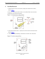
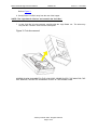
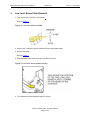
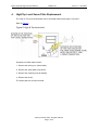
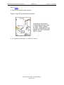
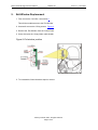
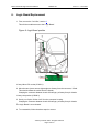
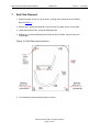
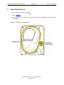
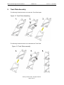
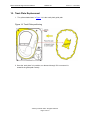
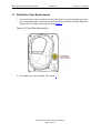
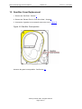
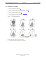
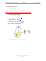
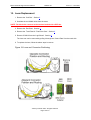
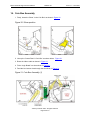
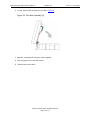
MKIV Universal Hopper Service Manual
TSP053.doc
Issue 2.1 – June 2004
This document is the copyright of Money Controls Ltd and may not be reproduced in part or in total by any means,
electronic or otherwise, without the written permission of Money Controls Ltd. Money Controls Ltd does not accept
liability for any errors or omissions contained within this document. Money Controls Ltd shall not incur any
penalties arising out of the adherence to, interpretation of, or reliance on, this standard. Money Controls Ltd will
provide full support for this product when used as described within this document. Use in applications not covered
or outside the scope of this document may not be supported. Money Controls Ltd. reserves the right to amend,
improve or change the product referred to within this document or the document itself at any time.
©Money Controls 2004. All rights reserved.
MKIV Universal Hopper Service Manual
TSP053.doc
Issue 2.1 – June 2004
Contents
1. Diary of Changes ........................................................................................................................................... 3
2. Coin Box Removal ......................................................................................................................................... 4
3. Low Level Sense Plate Removal .................................................................................................................. 6
4. High/Top Level Sense Plate Replacement................................................................................................... 7
5. Exit Window Replacement ............................................................................................................................ 9
6. Logic Board Replacement .......................................................................................................................... 10
7. End Plate Removal ...................................................................................................................................... 11
8. Track Plate Removal.................................................................................................................................... 12
9. Track Plate Assembly.................................................................................................................................. 13
10.
Track Plate Replacement ........................................................................................................................ 14
11.
Final Drive Gear Replacement................................................................................................................ 15
12.
Gear Box Cover Replacement ................................................................................................................ 16
13.
Gear Box Assembly................................................................................................................................. 17
14.
Motor Replacement ................................................................................................................................. 18
15.
Loom Replacement.................................................................................................................................. 19
16.
Coin Box Assembly ................................................................................................................................. 20
17.
Cleaning ................................................................................................................................................... 22
17.1
Health and Safety .................................................................................................................................. 22
17.2
Cleaners ................................................................................................................................................ 22
17.21
AIR DUSTERS............................................................................................................................... 22
17.22
SWABS.......................................................................................................................................... 22
17.23
CLEANING CLOTHS..................................................................................................................... 22
17.24
MILD DETERGENTS..................................................................................................................... 22
Figures
Figure 1: Low level sensor crimp positions .............................................................................................................. 4
Figure 2: Coin box screw positions.......................................................................................................................... 4
Figure 3: Coin box removal ..................................................................................................................................... 5
Figure 4: Low level stud assembly........................................................................................................................... 6
Figure 5: Low level sense plates position ................................................................................................................ 6
Figure 6: High & Top level studs.............................................................................................................................. 7
Figure 7: High & Top level sense positions ............................................................................................................. 8
Figure 8: Exit window position ................................................................................................................................. 9
Figure 9: Logic Board position ............................................................................................................................... 10
Figure 10: End Plate screw positions .................................................................................................................... 11
Figure 11: Elevator track position .......................................................................................................................... 12
Figure 12: Track Plate dismantling ........................................................................................................................ 13
Figure 13: Track Plate assembly ........................................................................................................................... 13
Figure 14: Track Plate positioning ......................................................................................................................... 14
Figure 15: Final Drive Gear position ...................................................................................................................... 15
Figure 16: Gear Box Cover position ...................................................................................................................... 16
Figure 17: Gear Box Assembly.............................................................................................................................. 17
Figure 18: Motor screw positions........................................................................................................................... 18
Figure 19: Loom and Connector Positioning ......................................................................................................... 19
Figure 20: Stirrer position ...................................................................................................................................... 20
Figure 21: Coin Box Assembly (1) ......................................................................................................................... 20
Figure 22: Coin Box Assembly (2) ......................................................................................................................... 21
©Money Controls 2004. All rights reserved.
Page 2 of 23
MKIV Universal Hopper Service Manual
1.
TSP053.doc
Issue 2.1 – June 2004
Diary of Changes
Issue 1.0…………………………………………………………………………..…8th September 2002
First issue in new format
Issue 2.0…………………………………………………………………………..……….13th April 2003
Applied TMWP 3.2
Improved all drawings
Added Figure 19: Loom and Connector Positioning.
Issue 2.1…………………………………………………………………………..……….30th June 2004
Changed footer
©Money Controls 2004. All rights reserved.
Page 3 of 23
MKIV Universal Hopper Service Manual
2.
TSP053.doc
Issue 2.1 – June 2004
Coin Box Removal
1. Place the hopper in front of you as shown, (looking at the outside of the ‘Coin Box’).
Refer to Figure 1.
2. Remove the 2 locking nuts which hold the ‘Low Level Sense Plate’ wires to the studs.
3. Remove the crimp & wire from the studs.
Figure 1: Low level sensor crimp positions
4. If other sense plates are used, i.e. High/Top, then refer to section 4 otherwise continue.
Refer to Figure 2.
5. Remove the 5 screws indicated (A), which hold the ‘Coin Box’ to the ‘Centre Plate’.
Figure 2: Coin box screw positions
©Money Controls 2004. All rights reserved.
Page 4 of 23
MKIV Universal Hopper Service Manual
TSP053.doc
Issue 2.1 – June 2004
Refer to Figure 3.
6. Gently lift the ‘Coin Box’ away from the rest of the hopper.
NOTE:- The ‘Logic Board’ & ‘Stirrer’ are located in the ‘Coin Box’.
7. As the ‘Coin Box’ is being removed, carefully slide the ‘Logic Board’ out. The stirrer may
stay with the ‘Coin Box’ or fall onto the centre plate.
Figure 3: Coin box removal
ACCESS IS NOW AVAILABLE TO THE ‘LOW LEVEL’ SENSE PLATES, THE MAIN PCB, THE
EXIT WINDOW, THE MOTOR TERMINALS & PART OF THE WIRING LOOM.
©Money Controls 2004. All rights reserved.
Page 5 of 23
MKIV Universal Hopper Service Manual
3.
TSP053.doc
Low Level Sense Plate Removal
1. First, remove the ‘Coin Box’, see section 2.
Refer to Figure 4.
Figure 4: Low level stud assembly
2. Remove the 2 remaining nuts & washers from the sense plate studs.
3. Remove the studs.
Refer to Figure 5.
4. Slide the sense plates away from the ‘Coin Box’ & remove.
Figure 5: Low level sense plates position
5. To re-assemble, follow the above steps in reverse.
©Money Controls 2004. All rights reserved.
Page 6 of 23
Issue 2.1 – June 2004
MKIV Universal Hopper Service Manual
4.
TSP053.doc
Issue 2.1 – June 2004
High/Top Level Sense Plate Replacement
The ‘High’ & ‘Top’ level sense plates can be accessed without removing the ‘Coin Box’.
Refer to Figure 6.
Figure 6: High & Top level studs
Irrespective of which plate is fitted :1. Remove the locking nut, (where fitted).
2. Remove the sense plate crimp & wire.
3. Remove the remaining nuts & washers.
4. Remove the stud/s.
The sense plate can now be removed.
©Money Controls 2004. All rights reserved.
Page 7 of 23
MKIV Universal Hopper Service Manual
TSP053.doc
Refer to Figure 7.
5. Place the relevant sense plate in position.
Figure 7: High & Top level sense positions
6. To re-assemble, follow steps 1 to 4, above, in reverse.
©Money Controls 2004. All rights reserved.
Page 8 of 23
Issue 2.1 – June 2004
MKIV Universal Hopper Service Manual
5.
TSP053.doc
Exit Window Replacement
1. First, remove the ‘Coin Box’, see section 2.
This will then enable access to the ‘Exit Window’
2. Unscrew & remove the 2 fixing screws. Figure 8.
3. Remove the ‘Exit Window’ from the ‘Centre Plate’.
4. Unclip & remove the 10 way ribbon cable header.
Figure 8: Exit window position
5. To re-assemble, follow the above steps in reverse.
©Money Controls 2004. All rights reserved.
Page 9 of 23
Issue 2.1 – June 2004
MKIV Universal Hopper Service Manual
6.
TSP053.doc
Issue 2.1 – June 2004
Logic Board Replacement
1. First, remove the ‘Coin Box’, section 2.
This will then enable access to the ‘Logic Board’.
Figure 9: Logic Board position
10 way ribbon IDC socket (CONN 1).
2. Move the two ejector arms at right angles to & away from the connector, if fitted.
This should release the socket from the header.
Clasping the connector between thumb & forefinger, pull away from pin header.
14 way crimp socket (CONN 2).
3. Gently, un-clip the “friction lock” from the connector housing.
Clasping the connector between thumb & forefinger, pull away from pin header.
The Logic Board is now released.
4. To re-assemble, follow the above steps in reverse.
©Money Controls 2004. All rights reserved.
Page 10 of 23
MKIV Universal Hopper Service Manual
7.
TSP053.doc
Issue 2.1 – June 2004
End Plate Removal
1. Place the hopper in front of you as shown, (looking at the outside of the ‘End Plate’).
Refer to Figure 10.
2. Remove the 9 screws indicated (B), which hold the ‘End Plate’ to the ‘Centre Plate’.
3. Locate the position of the ‘Connector Blanking Plate’.
4. Holding the ‘Connector Blanking Plate’ gently lift the ‘End Plate’ away from the rest
of the hopper.
Figure 10: End Plate screw positions
5. To re-assemble, follow the above steps in reverse.
©Money Controls 2004. All rights reserved.
Page 11 of 23
MKIV Universal Hopper Service Manual
8.
TSP053.doc
Issue 2.1 – June 2004
Track Plate Removal
1. First, remove the ‘End Plate’, section 7.
.
.
Refer to Figure 11.
2. The ‘Elevator Track’ & ‘Final Drive Gear’ can now be removed by lifting up & away from the
‘Centre Plate’.
Figure 11: Elevator track position
©Money Controls 2004. All rights reserved.
Page 12 of 23
MKIV Universal Hopper Service Manual
9.
TSP053.doc
Track Plate Assembly
The following 3 sketches show how to take the ‘Track Plate’ apart.
Figure 12: Track Plate dismantling
The following 3 sketches show how to assemble the ‘Track Plate’.
Figure 13: Track Plate assembly
©Money Controls 2004. All rights reserved.
Page 13 of 23
Issue 2.1 – June 2004
MKIV Universal Hopper Service Manual
TSP053.doc
Issue 2.1 – June 2004
10. Track Plate Replacement
1. The yellow shaded area, in Figure 14, is the ‘track plate’ guide path.
Figure 14: Track Plate positioning
2. Once the ‘track plate’ is in position, turn the track through 720 0 to ensure it is
seated in the guide path correctly.
©Money Controls 2004. All rights reserved.
Page 14 of 23
MKIV Universal Hopper Service Manual
TSP053.doc
Issue 2.1 – June 2004
11. Final Drive Gear Replacement
1. Once the ‘Elevator Track’ is in place, the ‘Final Drive Gear’ can be fitted by placing the gear
over its mounting spindle, while lining the teeth up with the secondary drive gear, adjust the
.
‘Elevator Track’ so that the gear falls into place. Figure 15.
Figure 15: Final Drive Gear position
2. The end plate can now be re-fitted. See section 7.
©Money Controls 2004. All rights reserved.
Page 15 of 23
MKIV Universal Hopper Service Manual
TSP053.doc
12. Gear Box Cover Replacement
1. Remove the ‘End Plate’. Section 7.
2. Remove the ‘Elevator Track’ & ‘Final Drive Gear’. Section 8.
3. Unscrew the 2 gearbox cover screws & remove the cover. Figure 16.
Figure 16: Gear Box Cover position
Access to the gears is now possible. See Section 13.
©Money Controls 2004. All rights reserved.
Page 16 of 23
Issue 2.1 – June 2004
MKIV Universal Hopper Service Manual
TSP053.doc
13. Gear Box Assembly
1. Remove the ‘End Plate’. Section 7.
2. Remove the ‘Elevator Track’ & ‘Final Drive Gear’. Section 8.
3. Remove the gearbox cover. Section 12.
4. Remove the gears in the order as shown in Figure 17.
Figure 17: Gear Box Assembly
Access to the motor fixing screws is now possible.
5. To re-assemble, follow the above steps in reverse.
©Money Controls 2004. All rights reserved.
Page 17 of 23
Issue 2.1 – June 2004
MKIV Universal Hopper Service Manual
TSP053.doc
14. Motor Replacement
1. Remove the ‘Coin Box’. Section 2.
2. Unsolder the red & black wires from the motor.
NOTE: The black wire connects to the terminal marked with a RED dot.
3. Remove the ‘End Plate’. Section 7.
4. Remove the ‘Track Plate’ & ‘Final Drive Gear. Section 8.
5. Remove the gearbox cover. Section 12.
6. Dismantle the gearbox. Section 13.
7. Unscrew the 2 motor fixing screws. Figure 18.
Figure 18: Motor screw positions
8. To re-assemble, follow the above steps in reverse.
©Money Controls 2004. All rights reserved.
Page 18 of 23
Issue 2.1 – June 2004
MKIV Universal Hopper Service Manual
TSP053.doc
Issue 2.1 – June 2004
15. Loom Replacement
1. Remove the ‘Coin Box’. Section 2.
2. Unsolder the red & black wires from the motor.
NOTE: The black wire connects to the terminal marked with a RED dot.
3. Remove the ‘End Plate’. Section 7.
4. Remove the ‘Track Plate’ & ‘Final Drive Gear’. Section 8.
5. Remove CONN 2 from the ‘Logic Board’. Section 6.
The loom can now be removed by pulling it through the ‘Centre Plate’ from the track side.
6. To replace the loom, follow the above steps in reverse.
Figure 19: Loom and Connector Positioning
©Money Controls 2004. All rights reserved.
Page 19 of 23
MKIV Universal Hopper Service Manual
TSP053.doc
16. Coin Box Assembly
1. Firstly, locate the ‘Stirrer’ in the ‘Coin Box’ as shown in Figure 20.
Figure 20: Stirrer position
2. Line up the ‘Centre Plate’ & ‘Coin Box’ as shown below. Figure 21.
3. Route the ribbon cable as shown in Figure 21.
4. Fit the ‘Logic Board’ into slots shown in Figure 21.
5. Feed the level sense wires through the slot shown in Figure 21.
Figure 21: Coin Box Assembly (1)
©Money Controls 2004. All rights reserved.
Page 20 of 23
Issue 2.1 – June 2004
MKIV Universal Hopper Service Manual
TSP053.doc
6. Lift the ‘Centre Plate’ to meet the ‘Coin Box’. Figure 22.
Figure 22: Coin Box Assembly (2)
7. Align the ‘centre plate’ & ‘coin box’ & push together.
8. Turn the hopper over & refit the screws.
8. Refit the level sense wires.
©Money Controls 2004. All rights reserved.
Page 21 of 23
Issue 2.1 – June 2004
MKIV Universal Hopper Service Manual
TSP053.doc
Issue 2.1 – June 2004
17. Cleaning
All accessible parts of the coin route should be cleaned between 50,000 & 100,000 coins
(dependant on coin type) using a mild detergent on a damp cloth. No spray solvents should be
used.
Particular attention should be paid to the sensors at the coin exit, as excessive dirt build up on
the optical surfaces may cause unreliable coin counting.
17.1 Health and Safety
Due to the potential respiratory hazards, it is highly recommended that a facemask be worn
to prevent the inhalation of dust particles dislodged during the maintenance process.
17.2 Cleaners
The following cleaning products can be used for the maintenance of the hopper:
17.21 AIR DUSTERS
High pressure compressed inert gas to remove dust and loose particles.
17.22 SWABS
Lint free polyester swabs to clean otherwise difficult to access areas.
17.23 CLEANING CLOTHS
Soft lint free cloths to wipe down accessible surfaces of the compact hopper.
17.24 MILD DETERGENTS
This can be washing up solution mixed with warm water or a non-abrasive cleaner.
All these items can be purchased from suppliers such as RS and Farnell.
NB: ONLY USE MILD DETERGENTS SO AS NOT TO DAMAGE THE HOPPER.
©Money Controls 2004. All rights reserved.
Page 22 of 23
MKIV Universal Hopper Service Manual
TSP053.doc
Issue 2.1 – June 2004
This manual is intended only to assist the reader in the use of this product and
therefore Money Controls shall not be liable for any loss or damage whatsoever
arising form the use of any information or particulars in, or any incorrect use of the
product. Money Controls reserve the right to change product specifications on any
item without prior notice
©Money Controls 2004. All rights reserved.
Page 23 of 23


![TSP050 SCH2 User Manual V1[1].](http://vs1.manualzilla.com/store/data/005912572_1-7a45ce84788ca8c84bf3ae15dae5a757-150x150.png)
![TSP030 ccEuroTeach User Manual V1[1].4(2)](http://vs1.manualzilla.com/store/data/005682308_1-f9d13610d7f8864488377d3c706bdc7d-150x150.png)