1
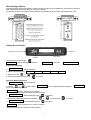
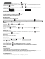
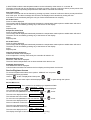
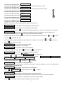
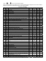
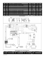
FVINO400HW
Foster Refrigerator
Oldmedow Road
Kings Lynn
Norfolk
PE30 4JU
Tel: 01553 691122
Fax: 01553 691447
Website: www.fosterrefrigerator.co.uk
Email: [email protected]
a Division of ‘ITW (UK) Ltd’
FV400HW /OP/ 0209
ISO 14001
ISO 9001
Contents
Environmental Management Policy
Disposal Requirements
Technical Data
Wine Storage Options
Alarms
Service Engineer Access
Parameters Cabinets & Counters
Wiring Diagram
1
1
1
2 to 3
3 to 4
4 to 6
6 to7
8
Environmental Management Policy for Service Manuals and Duets.
Product Support and Installation Contractors
Foster Refrigerator recognises that its activities, products and services can have an adverse impact upon the
environment.
The organisation is committed to implementing systems and controls to manage, reduce and eliminate its adverse
environmental impacts wherever possible, and has formulated an Environmental Policy outlining our core aims. A
copy of the Environmental Policy is available to all contractors and suppliers upon request.
The organisation is committed to working with suppliers and contractors where their activities have the potential to
impact upon the environment. To achieve the aims stated in the Environmental Policy we require that all suppliers
and contractors operate in compliance with the law and are committed to best practice in environmental
management.
Product Support and Installation contractors are required to:
1. Ensure that wherever possible waste is removed from the client’s site, where arrangements are in place all
waste should be returned to Foster Refrigerator’s premises. In certain circumstances waste may be disposed
of on the clients site; if permission is given, if the client has arrangements in place for the type of waste.
2. If arranging for the disposal of your waste, handle, store and dispose of it in such a way as to prevent its
escape into the environment, harm to human health, and to ensure the compliance with the environmental law.
Guidance is available from the Environment Agency on how to comply with the waste management ‘duty of
care’.
3. The following waste must be stored of separately from other wastes, as they are hazardous to the environment:
refrigerants, polyurethane foam, oils.
4. When arranging for disposal of waste, ensure a waste transfer note or consignment note is completed as
appropriate. Ensure that all waste is correctly described on the waste note and include the appropriate six-digit
code from the European Waste Catalogue. Your waste contractor or Foster can provide further information if
necessary.
5.
Ensure that all waste is removed by a registered waste carrier, a carrier in possession of a waste management
licence, or a carrier holding an appropriate exemption. Ensure the person receiving the waste at its ultimate
destination is in receipt of a waste management licence or valid exemption.
6. Handle and store refrigerants in such a way as to prevent their emission to atmosphere, and ensure they are
disposed of safely and in accordance with environmental law.
7. Make arrangements to ensure all staff who handle refrigerants do so at a level of competence consistent with
the City Guilds 2078 Handling Refrigerants qualification or equivalent qualification.
8.
Ensure all liquid substances are securely stored to prevent leaks and spill, and are not disposed of to storm
drains, foul drain, surface water to soil.
DISPOSAL REQUIREMENTS
If not disposed of properly all refrigerators have components that can be harmful to the environment. All old
refrigerators must be disposed of by appropriately registered and licensed waste contractors, and in accordance
with national laws and regulations.
Technical Data
Refrigerant
Refigerant
Charge
Compressor
Capillary
Defrost Type
Voltage
R134A
120 grms
Embraco
FG85HAK
3900mx 0.99mm
Timed Off Cycle
230-1-50
1
Power
Consumption
Watts
Amps
0.280
1.6
Fuse
Rating
13 Amp
Wine Storage Options
Multi temperature offers the possibility to keep wines at the right service temperature. Please refer to the table
below with the advised temperature for each wine category.
To preserve and age your wines choose the Mono Temperature option and set the temperature for 12ºC.
Mono Temperature
Multi Temperature
Setting the Controller
Setting the Controller
Down Button + Light Switch
OK Button
Menu Button
Up Button
Press and hold for 5 seconds
TURNING ON
(((((((( ))))))))
Will be displayed followed by
and then
BACCHUS GENIUS
Choose the Language
1/
LANGUAGE ↑↓ ?
Will be displayed
2/ Select the language from
3/ Select using the
ITALIAN
or
FRENCH ENGLISH GERMAN SPANISH
arrows.
4/ Once the selection is made press
to confirm.
Select the Mode of Operation
1/
MODE
↑↓ ?
Will be displayed
2/ Use the
or
to select either
for the multi temperature range.
MONO TEMP
for the single temperature range or
MONO TEMP Factory setting 8ºC as a default
Follow the instructions below to change the factory setting
1/
Temperature ↑↓?
Will be displayed press
2/ Select the required temperature by pressing
3/
Temperature? OK
MULTITEMP
to continue
or
and then press
Will be displayed press
to confirm.
Factory setting 3ºC to 18ºC as a default
Follow the instructions to change the factory setting
2
to confirm.
MULTI TEMP
1/
Temperature ↑↓?
Will be displayed press
to continue
2/ Select the lower temperature required by pressing
selected press
or
to confirm.
3/ Select the higher temperature required by pressing
selected press
On completion
once the preferred temperature has been
or
once the preferred temperature has been
to confirm.
CONFIRMED
will be displayed, followed by
HELLO WORLD
User Operation Guidelines
The cabinet will start automatically and display the set temperature.
To display the cabinet air temperature press
once.
Leave for two hours with the light off before loading
Main Menu Options
Only required if you need to change operation
To select a menu option press
MODE
and choose from the following, once selected press
m1 TEMPERATURE m2 Defrost
m3 Service
to access.
m4 TURN OFF
MODE m1
Allows the selection of MONO or MULTITEMP options
Press either
or
to select and
to confirm.
TEMPERATURE m2
Allows the temperature to be adjusted
To change press
confirm
followed by either
or
to select temperature option
DEFROST m3
Allows a manual defrost
The refrigerator will defrost automatically but should an additional defrost be required press
option and then press
and then
select this
to start the defrost.
SERVICE m4
Service engineer access (See page 4)
SWITCH OFF m5
To switch off the refrigerator select this option and press
The screen will display
Press
GOODBYE
followed by
STAND BY
PUSH>>>
to start.
Interior Light Operation
To turn the light on press
‘ON’ will flash and the light will be on continuously.
To turn the light off press
‘OFF’ will flash and the light will illuminate when the door is opened.
Alarms
High Temperature Alarm
HT will be displayed.
In MONO TEMP mode the high temperature alarm is indicated by sensor ‘A’.
In MULTITEMP mode the high temperature alarm can be indicated by either sensor ‘A’ or sensor ‘B’.
The alarm will sound and can be silenced by pressing any button, however it will return after a pre-set period. If the
unit returns to normal operating temperature the alarm will be cancelled automatically.
Low Temperature Alarm
LT will be displayed
In MONO TEMP mode the low temperature alarm is indicated by sensor ‘A’.
3
m5
In MULTITEMP mode the low temperature alarm can be indicated by either sensor ‘A’ or sensor ‘B’.
The alarm will sound and can be silenced by pressing any button, however it will return after a pre-set period. If the
unit returns to normal operating temperature the alarm will be cancelled automatically.
Door Open Alarm
The alarm will sound and can be silenced by pressing any button, however it will return after a pre-set period if the
door is left open. The alarm message will continue to be displayed until cancelled by closing the door.
If the alarm is not cancelled by doing this call your Foster authorised service company.
Air Probe Fault 1
Probe S1 will be displayed.
The message will be displayed intermittently between the temperature readout plus an audible alarm will sound.
The alarm can be cancelled by pressing any of the buttons on the display.
Action:
Replace probe.
Evaporator Probe Fault
Probe S2 will be displayed.
The message will be displayed intermittently between the temperature readout plus an audible alarm will sound.
The alarm can be cancelled by pressing any of the buttons on the display.
Action:
Replace probe.
Air Probe Fault 2
Probe S3 will be displayed.
The message will be displayed intermittently between the temperature readout plus an audible alarm will sound.
The alarm can be cancelled by pressing any of the buttons on the display.
Action:
Replace probe.
Overuse of the Compressor
COMPRES.WORK will be displayed.
If the compressor is running continuously the controller will switch it off.
Maximum Defrost Time
DEFROST TIME will be displayed.
The end of defrost temperature has not been reached within the time set.
Keyboard disconnection
PCD REMOVED will be displayed.
Communication has been lost between the front display and the printed circuit board
Service Engineer Access
To access the parameters select menu option 4 ‘SERVICE m4’ and press
The password will be requested.
Use the
till ‘07’ is displayed and then press
On completion the first menu option will be displayed press
to pass through the options.
Service Menu List
INFO
s1
Service Menu for the displaying of Operational Data
KEYPAD ON
To enter the Info list press
This indicates the Keypad status
To move from one parameter to the next use the
POWER ON
65355
will be displayed.
or
arrow.
or
arrow.
65355
The next to be displayed will be
This indicates the Power status
To move from one parameter to the next use the
The next to be displayed will be RESET 65355 : 23h
Gives an indication of when the controller was last reset.
65355 : 23h
The next to be displayed will be HTWL
Gives an indication of how long the controller is switched on.
COMP
65355 : 23h
The next to be displayed will be
This display the length of time the compressor has been running.
4
1h = 40%
The next to be displayed will be COMP%
Indicates the percentage of time during the last hour the compressor has been running.
24h = 40%
The next to be displayed will be COMP%
Indicates the percentage of time during the last 24 hours the compressor has been running.
4 01”
The next to be displayed will be COMP ON
Indicates the length of time the compressor has been on.
COMP OFF
9
17”
The next to be displayed will be
Indicates the length of time the compressor has been off.
The next to be displayed will be Fw 5102.77
Indicates the soft ware version of the controller.
The next to be displayed will be S/N
Indicates the controller serial number.
B.01
255. 255. 255.
NOTE: the figures in the box are representative and for indication only.
DEFROST LIST
s2
Service Menu for the displaying of Defrosting Data
FAILURE LIST
s3
Service Menu for the displaying of Failure Data
To enter the Info list press
s4
PARAMETERS
the screen will display the last fault i.e. Probe S1 indicating an air probe fault.
Service Menu for Parameter Programming (For the Parameter List go to page 6 to 7)
To enter the parameter list press
and the first parameter will be displayed.
The parameter number will start blinking. To move from one parameter to the next use the
or press
arrow
to display the value.
The value of the parameter selected will start blinking. To change the value use the
press
or
or
arrow then
to confirm the change.
INFOTEST DATA s5
Service Menu for the Infotest Data
Diagnostic check of the outputs from the controller
s6
TEST START
Service Menu for the Infotest Enabling
To start the diagnostic check press
s7
LANGUAGE
or
ESPANOL
to start the test.
Service Menu for changing the display Language
To enter the parameter list press
Press the
followed by
ITALIANA
will be displayed.
arrow to scroll through the following options:DEUTSCH
To select the language press
ITALIANA
FRANCHAISE
ENGLISH
followed by
to confirm.
MEMORY RESET s8
Service Menu for Deleting Memories
Allows for the deletion of all stored fault codes. These are stored memories relating to menu s1, operational data,
s2, defrost data, s3, and failure data.
PARAM. RESTORE s9
Service Menu for the Restoring of Parameters
< Esc Confirm >
Press
will be displayed press
The default parameters will be restored.
to confirm.
s10
PASWORD
Service Menu for Setting the Service Access Password
It is not recommended that the password is changed as it may restrict access by other service engineers.
INPUT/OUTPUT
Press
s11
Service Menu for Displaying the Sensor and Output States
to display the various probe temperatures and relay outputs.
5
Use the
or
keys to scroll through the displays.
NOTE: if the temperature is set for MONO only one probe temperature will be displayed where as if MULTITEMP is
selected the temperature as detected by all of the probes will be displayed.
Parameter Settings
No
1
2
3
4
5
6
7
8
9
10
11
12
13
14
15
16
17
18
19
20
21
22
23
24
25
26
27
28
29
30
31
32
33
34
35
36
37
38
39
40
Title
ADR
MOD
ISP
OSP
VOP
MES
DIN
DOO
OMA
OMB
DTX
DTD
SPO
HOS
HOC
SLO
SHO
ODA
ODB
SP1
H1S
H1C
SL1
SH1
SP2
H2S
H2C
SL2
SH2
HPO
URM
RH%
HRH
HRL
CND
ADL
ADS
CCD
CON
COF
41
CPH
42
43
44
45
46
47
48
49
50
51
52
53
54
55
56
DRP
DCM
DOP
ITD
DTO
DTE
DEO
FOP
FAS
FAD
FSD
HYW
ALL
ALH
ALD
57
ADD
58
59
60
LOG
SPT
CYC
Parameter Definitions
Serial Network Address
Function Mode Super Parameter
Input Setup
Output Setup
Display Contrast
Description Display Time Interval
Microdoor Option
Door Open Alarm Delay
S1 Probe Offset Mono Temp
S3 Probe Offset Mono Temp
Maximum Allowable Temperature Differential (Sb-Sa)
Recirculate Alarm Delay Time
Set Point (Mono Temperature Option)
Refrigeration Option Hysteresis (Single Temperature Option)
Heated Option Hysteresis (Single Temperature Option)
Minimum Temperature Set Point of SET 0
Maximum Temperature Set Point of SET 0
S1 Probe Offset Multi Temp
S3 Probe Offset Multi Temp
Temperature Set Point (cold zone)
Refrigeration Option Hysteresis Zone1 (cold zone)
Heated Option Hysteresis Zone 1 (cold zone)
Minimum Temperature Set Point of SET 1
Maximum Temperature Set Point of SET 1
Temperature Set Point (warm zone)
Refrigeration Option Hysteresis Zone2 (warm zone)
Heated Option Hysteresis Zone 2 (warm zone)
Minimum Temperature Set Point of SET 2
Maximum Temperature Set Point of SET 2
Humidity Sensor Setting
Humidification/Dehumidification Setting Mode
Humidity Set Point
Starting Dehumidification Out Let Hysteresis
Starting Humidification Out Let Hysteresis
Condenser Fan Start Delay Time
Minimum Time between Compressor Starts
Setting Delay Time after switching On
Setting Delay
Compressor ON Time During Compressor Failure
Compressor OFF Time During Compressor Failure
Compressor Working Operation Percentage (starting Time CONCOF)
Dripping Time After Defrost
Compressor Working Operation During Defrost
Defrost switch ON Option
Time Interval Between Defrosts
Defrost Time Out
Defrost Termination Temperature
Extra Defrost Time
Evaporator/Condenser Switch ON Option
Evaporator Fan set Point
Evaporator Fan Delay Time After Defrost
Evaporator Fan Set Point During Defrost
Warm-Air-Lock Fan Evaporator Turn ON/OFF Hysteresis
Low Temperature Alarm Differential
High Temperature Alarm Differential
Alarm Delay at Start Up
Alarm Delay After Turning ON, Defrosting and Loading Goods
Inside of Cabinet
Temperature Recording Setting Option
Temperature Record Test Time Interval
Number of Cycles to Perform in the INFOTEST Phase 1 and 7
6
Min
0
0
0
0
0
0
0
2
-15.0
-15.0
1.0
1.0
-30
0.0
0.0
-30
-30
-15.0
-15.0
-30
0.0
0.0
-30
-30
-30
0.0
0.0
-30
-30
-30
0
20
0
0
0
15
15
1
2
2
Max
99
3
255
255
255
255
2
60
15.0
15.0
20.0
250.0
30
15.0
15.0
30
30
15.0
15.0
30
15.0
15.0
30
30
30
15.0
15.0
30
30
30
15
90
20
20
240
240
240
120
255
255
Dim
flag
flag
flag
flag
flag
sec
flag
min
ºC/ºF
ºC/ºF
ºC/ºF
min
ºC/ºF
ºC/ºF
ºC/ºF
ºC/ºF
ºC/ºF
ºC/ºF
ºC/ºF
ºC/ºF
ºC/ºF
ºC/ºF
ºC/ºF
ºC/ºF
ºC/ºF
ºC/ºF
ºC/ºF
ºC/ºF
ºC/ºF
%
flag
%
%
%
min
sec
sec
sec
min
min
Setting
1
3
0
1
138
255
2
4
0
0
7
250
12
1
1.5
2
20
0
0
3
1
4
2
8
18
3
1
12
20
0
0
60
0
0
15
240
60
30
6
5
20
99
%
98
0
0
0
1
2
-50
0
0
-50
0
-50
0.5
-30
2
2
255
60
255
255
255
50
60
255
50
255
50
5.0
-2
60
255
sec
min
flag
hrs
min
ºC/ºF
min
flag
ºC/ºF
sec
ºC/ºF
ºC/ºF
ºC/ºF
ºC/ºF
min
180
0
5
6
90
6
0
3
45
15
1
1.5
-5
5
90
2
255
min
120
0
1
1
9
120
5
flag
min
flag
0
1
3
61
62
63
64
65
66
67
68
69
70
71
72
73
74
75
76
STA
ETT
PRT
PU1
PU2
PU3
PU4
PU5
PU6
PV1
PV2
PV3
PV4
PV5
PV6
Number of Stabilization Cycles in the INFOTEST Phase 0 and 6
Pull-Up Phase_4 in INFOTEST Temperature
Print Mode
Setting Let out U1 (relay 30A) – one temp. working
Setting Let out U2 (relay 8A) – one temp. working
Setting Let out U3 (relay 5A) – one temp. working
Setting Let out U4 (relay 5A) – one temp. working
Setting Let out U5 (relay 5A) – one temp. working
Setting Let out U6 (relay 5A) – one temp. working
Setting Let out U1 (relay 30A) – multi temp. working
Setting Let out U2 (relay 8A) – multi temp. working
Setting Let out U3 (relay 5A) – multi temp. working
Setting Let out U4 (relay 5A) – multi temp. working
Setting Let out U5 (relay 5A) – multi temp. working
Setting Let out U6 (relay 5A) – multi temp. working
Password
1
-30
0
0
0
0
0
0
0
0
0
0
0
0
0
0
5
30
3
255
255
255
255
255
255
255
255
255
255
255
255
255
flag
ºC/ºF
flag
flag
flag
flag
flag
flag
flag
flag
flag
flag
flag
flag
flag
flag
Wiring Diagram
TD
TD
TD
TD
TD
R
Wiring Diagram Item Code Identification
R1(S1)
PR2 (S2)
PR3 (S3)
Low Zone Probe
Defrost End Probe
High Zone Probe
MP
TD
R
Microswitch
Controller
Heater
T
LF
MC
Fvino/SM/0309
7
Ballast
Light
Compressor
MV1
MV2
KA
Condenser Fan
Evaporator Fan
Relay
3
15
0
1
4
13
18
29
0
1
9
32
18
29
0
7