1
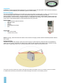
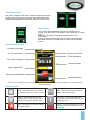
Dough Retarder Prover
Modular DRPTRI2 & 3 Models
FB1-11 Touchpad Controller
English
ISO 9001
ISO 14001
November 2014 Version 1
Original Service Manual
By Appointment to
Her Majesty Queen Elizabeth II
Suppliers of Commercial Refrigeration
Foster Refrigerator, King’s Lynn
A Division of ITW Ltd
Foster Refrigerator,
Oldmedow Road,
King’s Lynn,
Norfolk, PE30 4JU
United Kingdom
1
Contents
Page
Manual Information & Health & Safety Notes
1
Environmental Management Policy
2
Disposal Requirements & Electrical Safety
2
DRPTRI Model Installation & Electrical Supply
3
Start Up, Controller Display & Icons
4-5
How To Run Cycles
5-6
User Adjustment & Parameter Setting
7
FB1-11 Default Parameter Values & Descriptions
8-14
Model Specific Parameter Values
15-17
Wiring Diagrams
18-22
Relay & Footprint Testing
23
Technical Data
24
Troubleshooting
25-27
Service Manual Information:
The products and all information in this manual are subject to change without prior notice.
We assume by the information given that the person(s) working on these refrigeration units are
fully trained and skilled in all aspects of their workings. Also that they will use the appropriate safety equipment
and take or meet precautions where required.
The service manual does not cover information on every variation of this unit; neither does it cover the
installation or every possible operating or maintenance instruction for the units.
Health & Safety Warnings & Information
Make sure the power supply is turned off before making any electrical repairs.
To minimise shock and fire hazards, please do not plug or unplug the unit with wet hands.
During maintenance and cleaning, please unplug the unit where required.
Care must be taken when handling or working on the unit as sharp edges may cause
personal injury, we recommend the wearing of suitable PPE.
Ensure the correct moving and lifting procedures are used when relocating a unit.
Do NOT use abrasive cleaning products, only those that are recommended. Never scour
any parts of the refrigerator. Scouring pads or chemicals may cause damage by scratching
or dulling polished surface finishes.
Failure to keep the condenser clean may cause premature failure of the motor/compressor
which will NOT be covered under warranty policy.
Do NOT touch the cold surfaces in the freezer compartment. Particularly when hands are
damp or wet, skin may adhere to these extremely cold surfaces and cause frostbite.
Please ensure the appropriate use of safety aids or Personnel Protective Equipment (PPE)
are used for you own safety.
1
Environmental Management Policy
Product Support and Installation Contractors.
Foster Refrigerator recognises that its activities, products and services can have an adverse impact upon the
environment.
The organisation is committed to implementing systems and controls to manage, reduce and eliminate its adverse
environmental impacts wherever possible, and has formulated an Environmental Policy outlining our core aims. A copy
of the Environmental Policy is available to all contractors and suppliers upon request.
The organisation is committed to working with suppliers and contractors where their activities have the potential to
impact upon the environment. To achieve the aims stated in the Environmental Policy we require that all suppliers and
contractors operate in compliance with the law and are committed to best practice in environmental management.
Product Support and Installation contractors are required to:
1. Ensure that wherever possible waste is removed from the client’s site, where arrangements are in place all waste
should be returned to Foster Refrigerator’s premises. In certain circumstances waste may be disposed of on the
client’s site; if permission is given, if the client has arrangements in place for the type of waste.
2. If arranging for the disposal of your waste, handle, store and dispose of it in such a way as to prevent its escape
into the environment, harm to human health, and to ensure the compliance with the environmental law. Guidance is
available from the Environment Agency on how to comply with the waste management ‘duty of care’.
3. The following waste must be stored of separately from other wastes, as they are hazardous to the environment:
refrigerants, polyurethane foam, and oils.
4. When arranging for disposal of waste, ensure a waste transfer note or consignment note is completed as
appropriate. Ensure that all waste is correctly described on the waste note and include the appropriate six-digit
code from the European Waste Catalogue. Your waste contractor or Foster can provide further information if
necessary.
5. Ensure that all waste is removed by a registered waste carrier, a carrier in possession of a waste management
licence, or a carrier holding an appropriate exemption. Ensure the person receiving the waste at its ultimate
destination is in receipt of a waste management licence or valid exemption.
6. Handle and store refrigerants in such a way as to prevent their emission to atmosphere, and ensure they are
disposed of safely and in accordance with environmental law.
7. Make arrangements to ensure all staff who handle refrigerants do so at a level of competence consistent with the
City Guilds 2079 Handling Refrigerants qualification or equivalent qualification.
8. Ensure all liquid substances are securely stored to prevent leaks and spill, and are not disposed of into storm
drains, foul drain, or surface water to soil.
Disposal Requirements
If not disposed of properly all refrigerators have components that can be harmful to the
environment.
All old refrigerators must be disposed of by appropriately registered and licensed waste contractors, and in
accordance with national laws and regulations.
General Electrical Safety
Foster Refrigerator recommends that the equipment is electrically connected via a Residual Current Device; such as
a Residual Current Circuit Breaker (RCCB) type socket, or through a Residual Current Circuit Breaker with Overload
Protection (RCBO) supplied circuit.
2
Installation
Installation of these units should be carried out by a competent person and appropriate codes of practice adhered to
thus ensuring safe installation (see installation guide for further details).
Electrical Supply
The correct electrical installation must be adhered to where the DRP is supplied with an isolator. The electrical supply
must be terminated into the isolator in such a way that the supply can be controlled by the operator,
When the DRP is supplied with a 5 pole electrical plug. A single purpose clearly marked isolating socket; of the type
described below is to be provided to supply the DRP. The installation and testing of this socket should fall within the
scope of the normal testing regime for the fixed electrical wiring of the site.
Socket Type:
>
>
>
>
>
>
Switched with mechanical interlock
32A size socket
400Vac
50/60Hz
3Pole+Neutral and Earth
IP67
Fitted with:
>
>
20A 3 Phase MCB
3 Phase RCD (0.03A)
NOTE: The plug, cable and socket are rated to 32A; however the supply socket should have MCB protection fitted at
20A / phase.
Socket Position:
The DRP is supplied with sufficient cable such that the supply socket should be positioned within a 5M (5000mm)
radius from the centre of the DRP. This allows for the cable to route vertically 1M (1000mm) into a ceiling void, and
then down a supporting surface to the socket positioned at around 1500mm from the floor level.
5000mm
The socket must be positioned in sight of the DRP and readily accessible to act as an isolation point for the DRP.
A suitable label should be positioned on the DRP identifying the location of the isolating socket.
3
Initialisation Screen
After power is applied to the unit the controller display will show the
booting screen. This will only show for a few minutes stating both
‘Booting’ and then displaying ‘Initializing’. When the controller has
completed initialisation the screen will revert to the ‘Home’ screen.
'Home' Screen
This is shown after initialisation and when no programmes are
running. From this screen it is possible to run an automatic or manual
cycle.
Select the cycle type by pressing the relevant button on the
touchscreen.
This screen also shows the date, time and current air temperature
and allows access to the ‘Settings Home Screen’ and ‘Information’
function.
Touchpad Display Icons
Humidity Percentage
Air (T1) temperature
Day & Current Time
Cycle Description
Cycle Time Remaining
Surround Signal
Cycle Progress Bar
Stop/ Reset/ Hold Button
Information Button
(Some icons or switches are only visible during adjustment, when activated by parameters or through operation/
manual selection).
Buttons & Icons
Home – When selected on any screen
this will revert you to the ‘Home’ screen
Back - When pressed this will take you
back to the previous screen
Settings – This will take you into the
‘Settings Menu’ where changes can be
made to the language, date, time etc.
Information – When pressed this will
give a summary of what is currently happing with the unit
Alarm – Press this to view lists of active
and historic alarms
Delete – Use this to delete historic alarm
warnings that require clearing from the
‘Alarm Log’
4
Screen Feedback Signal
When an icon or button is selected on screen a single beep will be heard to confirm the action requested.
Surround Signal Colour Coding
These four different screen surround signal colours represent the following:
Service or Maintenance
Mode. User modification in
progress.
Controller not operating or
in Standby. Unit is ready
for use.
Process or system issue.
User intervention required.
Cycle under way or unit on
operation. User attention
not required.
Stopping a Cycle or Function
When shown on screen you can press and hold ‘Stop’, Finish’ or ‘Reset’ for 3 seconds, or until he progress blocks fill
to halt a cycle or function.
They must be pressed and held until the progression blocks are filled. If the process blocks are not filled the cycle will
not stop and will continue the cycle.
How to Run an Automatic Cycle
Select &
press ‘Auto’
Adjust end
date & time
then press
‘Start’
During the ‘Bake
Time’ cycle the
progress bar will
fill and the time
counts down.
The cycle phase
is indicated in
steps (as shown
to the left).
5
The alarm
will sound to
advise that the
unit is ready for
product to be
loaded. Load
product & press
‘Run’
The alarm will
sound and then
you can either
extend the cycle
or finish it (see
next section for
details)
Finish the Cycle
Extend the Cycle
Press the ’Extend’
button and you will be
taken to the Set Timer
display. Set the timer
and then press ‘Start’
To finish the cycle press
the ‘Finish’ button and
the cycle will end then
revert the display to the
‘Home’ screen.
How to Run a Manual Cycle
Select
& press
‘Manual’
Press
‘Timer’ to
edit the
cycle time.
Timer
shows.
Select new
cycle with
‘Timer’ or
press and
hold ‘Stop’
to end.
Alarm sounds,
load product &
press ‘Run’
Auto’ Adjust
end date &
time. Press
‘Start’
Adjust time
& press
‘Start’
Progress bar
fills & time
counts down
Press & hold
‘Stop’.
After ending
the cycle
the ‘Home’
screen will
be shown.
Silence an Alarm
Load Alarm – press the green ‘Run’ button to continue the cycle and confirm
product has been loaded into the unit
Fault Alarm – Press the ‘Mute’ button to silence followed by the ‘i’ button for more
information on the fault/warning.
6
User Adjustment Modes
The following three screen options can all be accessed by starting from the ‘Home’ screen then
by using the ‘Settings Icon’, select the ‘Settings Home Screen’. From here you can then select
the menu required:
Time/Date Setting Menu
Select 'set
Time & Date'
Use directional
arrows to set
time & date.
Press 'Set'
to confirm or
changes will be
lost.
Languages
This controller only shows text in English
Service Settings Menu
Parameters
Access to this menu is vital if you wish to adjust any parameter settings.
Select
'Service
Settings'
Using arrows
enter access
code 1,3,1.
If left for 20
seconds the
home screen
will show.
Press 'Enter'
If entered
incorrectly the
'home' screen
will show. If
correct the
service screen
shows.
Select the
parameter set
you wish to
adjust.
Cycle Parameter Sets
Parameters should not be changed unless you have an understanding of their purpose and the following
instructions are fully understood.
This ‘Service Setting’ screen allows access to control and system parameter set up for the 2 cycle types 'Auto' and
'Manual' along with the 'System' set up and the relay test facility.
To amend a ‘Cycle’ please follow these instructions after selecting the parameter set you wish to amend (as described
above). If at any time the screen is left for 20 seconds amendments will be lost and the 'Home' screen will be shown:
Scroll
through list
with up or
down arrows
on screen.
Select the
parameter to
amend.
Select new
option
Use cross
or tick to
confirm or
reject new
value and
return to
set menu.
Depending
on parameter
type will show
either
Type new
value.
Select another
parameter
to amend or
press the
green tick to
exit.
To amend ‘System’ parameters the function is exactly as described above you just need to select ‘System’ rather than
a cycle option.
7
FB1-11 Default Controller Parameter Values - Auto Cycle
Section
Chill
Phase
Retard
Phase
Recovery
Phase
Prove
Phase
Hard
Phase
Parameter
Range
Description
Default
Setting
Chill Duration
0 to 360 min
Duration of the chill phase.
60
Chill Set Point
-50 to 120°
Chill phase temperature set point.
-8
Chill Hysteresis
0 to 25°
Chill phase temperature hysteresis.
3
Chill Load Temp
-50 to 120°
Auto cycle ‘Do not load product’ temperature
threshold offset point.
0
Chill Fan Speed
0 to 100
Evaporator fan speed during chill phase.
Retard Set Point
-50 to 120°
Retard phase temperature set point.
-5
Retard Hysteresis
0 to 25°
Retard phase temperature hysteresis.
3
Retard Fan Speed
0 to 100%
Evaporator fan speed during retard phase.
75
Recovery Duration
0 to 600 min
Recovery phase duration.
360
Recovery Set Point
-50 to 120°
Recovery phase temperature set point.
8
Recovery Hysteresis
-50 to 25°
Recovery phase temperature hysteresis.
3
Recovery Lift
0 to 100%
Recovery lift percentage (amount of recovery duration time to raise the temperature to recovery set
point).
65
Rec. Lift Fan Speed
0 to 100%
Evaporator fan speed during recovery lift phase.
100
Rec. Fan Speed
0 to 100%
Evaporator fan speed during recovery phase.
100
Rec. Humidity Set
0 to 100%
Recovery phase humidity setting.
85
Prove Duration
0 to 600 min
Prove phase duration.
240
Prove Set Point
-50 to 120°
Prove phase temperature set point.
30
Prove Chill Hysteresis
0 to 25°
Prove chill hysteresis – the differential from the
set point before switching on cooling (subject to
compressor rest).
2
Prove Heat Hysteresis
-25 to 0°
Prove heat hysteresis – the differential from the
set point before switching on heating (subject to
compressor rest).
2
Prove Lift
0 to 100%
Prove phase lift percentage (amount of prove
duration time taken to raise the temperature to the
prove set point).
50
Prove Lift Fan Speed
0 to 100%
Evaporator fan speed during lift phase.
85
Prove Off Fan Speed
0 to 100%
Evaporator fan speed during prove ‘off’ cycle.
50
Prove On Fan Speed
0 to 100%
Evaporator fan speed during prove heating or cooling cycle.
85
Prove Humidity Set
0 to 100%
Prove phase humidity setting.
85
Hold Enable
NO or YES
Determination of hold function (NO = cycle stop +
alarm sounds, YES = alarm sounds after ‘Auto End
Timeout’ Hold is initiated, alarm muted).
NO
Hold Set Point
-50 to 120°
Hold mode temperature set point.
15
Hold Hysteresis
0 to 25°
Hold mode hysteresis.
3
Hold Fan Speed
0 to 100%
Evaporator fan speed during hold mode.
80
Hold Humidity Set
0 to 100%
Hold mode humidity setting.
85
100
8
FB1-11 Default Controller Parameter Values - Manual Cycle
Section
Range
Description
Manual Set Point
-50 to 120°
Manual prove temperature set point.
30
Manual Chill Hysteresis
0 to 25°
Refrigeration ‘On’ differential point – if T1>(‘Manual
Set Point’ + ’Man Chill Hys’), then refrigeration
switched on (subject to ‘Comp. Reset Time’).
3
Manual Heat Hysteresis
-25 to 0°
Heating ‘On’ differential point – if T1<(‘Manual
Set Point’ – ‘Man. Heat Hys’), then prove heaters
switched on.
1
Manual Load
Temperature
-20 to 50°
Manual Cycle ‘ Do not load product’ temperature
threshold set point.
20
Manual Fan Speed
0 to 100%
Manual prove fan speed.
100
Manual Humidity Set
0 to 100%
Manual prove humidity setting.
85
Clock Format
12/24 hr.
Display/ setting format for time clock.
24H
Daylight Saving Time
NO or YES
Daylight saving time adjustment on last Sunday in
March (reverts back last Sunday in October).
YES
Auto Wait Timeout
0 to 120 min
Length of time in Auto phase that ‘WAIT’ is displayed before de-energising relays, stopping the
cycle and displaying ‘WARNING’ page without
achieving temperature.
30
0 to 120 min
Length of time in Auto phase that ‘LOAD’ is displayed before de-energising relays, stopping the
cycle and returning to ‘Home’ screen with no intervention.
60
0 to 120 min
Length of time in Auto phase that ‘EXTEND/ FINISH’ is displayed before de-energising relays,
stopping the cycle with no intervention (‘HOLD’ not
enabled) – EOC continue.
10
0 to 120 min
Length of time in Manual phase that ‘WAIT’ is
displayed before de-energising relays, stopping
the cycle and displaying ‘WARNING’ page without
achieving temperature.
30
0 to 120 min
Length of time in Manual phase that ‘LOAD’ is
displayed before de-energising relays, stopping
the cycle and returning to ‘Home’ screen with no
intervention.
60
Auto Load Timeout
Manual
Prove
Default
Setting
Parameter
Auto End Timeout
Manual Wait Timeout
Manual Load Timeout
Temperature alarm threshold configuration:
NON
All temperature alarms are inhibited.
RELATED
The value set in ‘Low Diff’ & ‘High Diff’ are alarm
differentials which relate to phase set point and
cycle.
Low Temp Alarm Diff
-9.9 to 0°
Low temperature alarm differential. (With ‘Low
temp. air diff’ = ‘0’ the low temperature alarm is
excluded).
-5
High Temp Alarm Diff
0 to 9.9°
High temperature alarm differential. (With ‘High
temp. air diff’ = ‘0’ the high temperature alarm is
excluded).
5
Temperature Alarm
NON
Temperature alarm probe:
Temperature Alarm
Probe
9
T1
Air temperature probe used for alarm detection.
T2
Evaporator temperature probe used for alarm detection (If ‘Evaporator Probe Enable’ = YES).
T3
Third temperature probe used for alarm detection
(If ‘Auxiliary Input’ = ‘Cond’).
T1
FB1-11 Default Controller Parameter Values - System
Section
System
Parameter
Range
Description
Default
Setting
Temperature Alarm
Delay
0 to 120 min
Delay before alarm temperature warning.
30
Door Alarm Delay
0 to 30 min
Delay before ‘Door Open’ alarm warning.
8
Evaporator Fan Min
Stop
0 to 90 sec
Minimum evaporator fan stop period (following door
opening etc.)
0
Compressor Rest Time
0 to 30 min
Compressor rest time.
1
Control Hum. Thr.
-0 to 90°
Humidity temperature threshold (temperature at
which humidity control is enabled).
15
Humidity Low
-10 to 0%
Variation below humidity set point level before
humidity system activation.
-3
Humidity High
0 to 10%
Variation above humidity set point at which refrigeration system/ humidity alarm activation.
2
Humidity Alarm Delay
0 to 120 min
Delay before humidity alarm warning
30
Humidity Probe Offset
-10 to 10%
Humidity probe offset.
0
Humidity Simulation
0 to 100
Displayed humidity slowdown.
10
Power Fail Alarm
0 to 120 min
Power failure alarm time (if ‘Power fail alarm’ = ‘0’
power failure alarm is disabled).
0
Cond. Clean Warn.
0 to 52
Weeks
Condenser clean period. (With ‘Cond. Clean warn’
= ‘0’ condenser cleaning alarm is disabled.
0
Data Logger
NO or YES
Data collection and download function (FCOM fitted/ download icon displayed).
NO
Screensaver Tmt
0 to 120 min
Tim before starting screensaver from ‘Home’
screen (with value ‘0’ screensaver is not enabled
and display remains constantly illuminated).
0
Configurable digital input operation:
Not Used
(NON)
Digital input not activated.
Door Switch
(DOOR)
Door switch input (if ‘Digital IP 0’ = ‘DOOR’ next
parameter will be ‘DOOR DELAY’).
Light Switch
(LIGHT)
Light switch operation (‘Relay 5’ = ‘LIGHT’ +
‘LIGHT MODE’ = MANUAL).
Alarm If
Open (AL
OPN)
Alarm (‘AL’ displayed) when contact opens.
Alarm If
Closed (AL
CLS)
Alarm (‘AL’ displayed) when contact closes.
High Pressure Switch
NO or YES
Configurable 230Vac Input (D3) from high pressure
switch to operate high pressure alarm.
YES
Low Pressure Switch
NO or YES
Configurable 230Vac Input (DS) from low pressure
switch to operate low pressure alarm.
NO
Over Temp Switch
NO or YES
Configurable 230Vac Input (DS) from over temp
stat to operate over temp alarm.
YES
Digital Input 0
NON
10
Section
Parameter
Range
Description
Default
Setting
Relay 2 Operation (relay contacts open when
mains power removed):
Not Used
(NON)
Output disabled (always off).
Steam
Heater
(ST HTR)
Control of humidity steam generator heater (activated in both ‘TANK’ and ‘PULSE’ mode).
Prove Heater Control of prove heater.
(PROVE)
Relay 2
Steam Valve
(ST VLV)
Control of water solenoid valve (used with ‘PULSE’
humidity setting).
EOC Alarm
(EOC)
Energises at end of cycle for indication.
Light
(LIGHT)
Output enabled for light control.
0-1 (0-1)
Contacts open/closes with ‘Run/ Standby’ mode.
Open In
Alarm (AL
OPN)
Contacts open when an alarm condition occurs.
Closed
Alarm (AL
CLS)
Contacts close when an alarm condition occurs.
ST
HTR
EOC + Open Energises at end of cycle for indication but contacts
In Alarm
open when an alarm condition occurs.
(EOC+AL)
System Continued
Relay 3 Operation (relay contacts open when
mains power removed):
Not Used
(NON)
Output disabled (always off).
Steam
Heater
(ST HTR)
Control of humidity steam generator heater (activated in both ‘TANK’ and ‘PULSE’ mode).
Prove Heater Control of prove heater.
(PROVE)
Relay 3
Steam Valve
(ST VLV)
Control of water solenoid valve (used with ‘PULSE’
humidity setting).
EOC Alarm
(EOC)
Energises at end of cycle for indication.
Light
(LIGHT)
Output enabled for light control.
0-1 (0-1)
Contacts open/closes with ‘Run/ Standby’ mode.
Open In
Alarm (AL
OPN)
Contacts open when an alarm condition occurs.
Closed
Alarm (AL
CLS)
Contacts close when an alarm condition occurs.
EOC + Open Energises at end of cycle for indication but contacts
In Alarm
open when an alarm condition occurs.
(EOC+AL)
11
PROVE
Section
Parameter
Range
Description
Default
Setting
Relay 4 Operation (relay contacts open when
mains power removed):
Not Used
(NON)
Output disabled (always off).
Steam
Heater
(ST HTR)
Control of humidity steam generator heater (activated in both ‘TANK’ and ‘PULSE’ mode).
Prove Heater Control of prove heater.
(PROVE)
Relay 4
Steam Valve
(ST VLV)
Control of water solenoid valve (used with ‘PULSE’
humidity setting).
EOC Alarm
(EOC)
Energises at end of cycle for indication.
Light
(LIGHT)
Output enabled for light control.
0-1 (0-1)
Contacts open/closes with ‘Run/ Standby’ mode.
Open In
Alarm (AL
OPN)
Contacts open when an alarm condition occurs.
Closed
Alarm (AL
CLS)
Contacts close when an alarm condition occurs.
NON
EOC + Open Energises at end of cycle for indication but contacts
In Alarm
open when an alarm condition occurs.
(EOC+AL)
System Continued
Relay 5 Operation (relay contacts open when
mains power removed):
Not Used
(NON)
Output disabled (always off).
Steam
Heater
(ST HTR)
Control of humidity steam generator heater (activated in both ‘TANK’ and ‘PULSE’ mode).
Prove Heater Control of prove heater.
(PROVE)
Relay 5
Steam Valve
(ST VLV)
Control of water solenoid valve (used with ‘PULSE’
humidity setting).
EOC Alarm
(EOC)
Energises at end of cycle for indication.
Light
(LIGHT)
Output enabled for light control.
0-1 (0-1)
Contacts open/closes with ‘Run/ Standby’ mode.
Open In
Alarm (AL
OPN)
Contacts open when an alarm condition occurs.
Closed
Alarm (AL
CLS)
Contacts close when an alarm condition occurs.
EOC
EOC + Open Energises at end of cycle for indication but contacts
In Alarm
open when an alarm condition occurs.
(EOC+AL)
12
Section
Parameter
Range
Description
Default
Setting
Relay 6 Operation (relay contacts open when
mains power removed):
Not Used
(NON)
Output disabled (always off).
Steam
Heater
(ST HTR)
Control of humidity steam generator heater (activated in both ‘TANK’ and ‘PULSE’ mode).
Prove Heater Control of prove heater.
(PROVE)
Relay 6
System Continued
Steam Valve
(ST VLV)
Control of water solenoid valve (used with ‘PULSE’
humidity setting).
EOC Alarm
(EOC)
Energises at end of cycle for indication.
Light
(LIGHT)
Output enabled for light control.
0-1 (0-1)
Contacts open/closes with ‘Run/ Standby’ mode.
Open In
Alarm (AL
OPN)
Contacts open when an alarm condition occurs.
Closed
Alarm (AL
CLS)
Contacts close when an alarm condition occurs.
AL CLS
EOC + Open Energises at end of cycle for indication but contacts
In Alarm
open when an alarm condition occurs.
(EOC+AL)
Alr Repeat Interval
0 to 720 min
Time between an acknowledged alarm being
muted and resounding (when it still exists). If ‘R6
RPT INT’ = ‘0’ the alarm will not record.
EOC Max Duration
0 to 720 min
The time the ‘End of Cycle’ (EOC) alarm sounds for
before automatically muting (If ‘EOC PERIOD’ = ‘0’
the EOC alarm will not automatically mute).
Light Control Mode:
Light Mode
Not Used
(NON)
Light control mode disabled (always off).
DI0 Open
(DO OPN)
Light control is switched on when door is opened (If
‘DIGITAL IP 0’ = ‘Light’).
DI0 Closed
(DO CLS)
Light control is switched on when door is closed (If
‘DIGITAL IP 0’ = ‘Light’).
Door Open
(DR OPN)
Light control is switched on when door is opened (If
‘DIGITAL IP 0’ = ‘Door’).
Door Closed
(DR CLS)
Light control is switched on when door is closed (If
‘DIGITAL IP 0’ = ‘Door’).
NON
Steam generation control mode:
Steam Control
13
Not Used
(NON)
Steam control is disabled (always off).
Tank (TANK)
Steam is generated by tank heater (then ‘Relay 2’ =
‘Steam Htr’).
Pulse
(PULSE)
Steam is generated by grid heater and injector
(then ‘Relay 2’ = ‘Steam Htr’ + ‘Relay 4’ = ‘Steam
Vv’).
TANK
Section
Default
Setting
Parameter
Range
Description
Hum. Power Thr
-1% to -30%
Point before humidity setpoint at which generation
is switched from 100% power to value determined
by ‘Steam Htr. On/ Steam Htr. Off’.
-15
Steam Htr. On
30 to 240
sec
Cyclic steam heater ‘On’ when generating humidity
as determined by ‘Hum. Power Thr’.
60
Steam Htr. Off
30 to 240
sec
Cyclic steam heater ‘Off’ when generating humidity
as determined by ‘Hum. Power Thr’.
45
Pulse Delay
0 to 120 sec
Delay time between humidity heater (Relay 2) being switched on and water valve (Relay 4) being
energised.
20
Pulse On
0 to 120 sec
Relay 4 steam valve operating cycle (open time)
when humidity is required (i.e. the period of time
relay 4 energised/ valve open).
1
Pulse Off
0 to 120 sec
Relay 4 steam valve operating cycle (closed time)
when humidity is required (i.e. the period of time
relay 4 de-energised/ valve shut).
10
Air Probe Offset
‘-9.9 to 9.9°C Air temperature probe (T1) enabling.
Evap Probe Enable
NO or YES
Evap Probe Offset
‘-9.9 to 9.9°C Evaporator temperature probe (T2) offset.
Evaporator (T2) probe enabling.
0
NO
0
T3 Probe Function:
System Continued
Auxiliary Input
Not Used
(NON)
Digital input T3 not activated.
Door2
(DOOR2)
Door switch input (works in series with ‘DO’ when
‘DO’ = ‘DS’), (If ‘T3’ = ‘DOOR2’ parameter ‘DOOR
DELAY’ is activated).
Alarm If
Open
(AL OPN)
Alarm switch – ‘general alarm’ displayed when
contact is open.
Alarm If
Closed
(AL CLS)
Alarm switch – ‘general alarm’ displayed when
contact is closed.
HP Switch
(HP)
High pressure switch digital input (normally closed/
alarm when open).
Display
(DISP.)
T3 probe temperature displayed in place of T1 (T1
value controls thermostatic cycle).
Condenser
(COND.)
Condenser temperature measurement.
NON
Aux Probe Offset
‘-9.9 to 9.9°C Auxiliary temperature probe (T3) offset.
0
Cond. Alarm Temp
-50 to 90°C
65
Condenser alarm temperature.
Readout Scale:
0.1°C
(0.1°C)
Range -50 to 120°C (0.1°C resolution within -9.9 to
+9.9°C).
1°C
(1°C)
Range -50 to 120°C.
1°F
(1°F)
Range -58 to 200°F.
Thermal Simulation
0 to 100
Displayed temperature slow down.
0
Address
1 to 255
FB1-11 address for PC communication.
1
Display Scale
0.1°C
(Parameters correct at time of issue - FB1-11 Version 1.10)
14
FB1-11 Default Controller Parameter Values - System
Parameter
(as displayed on screen)
Section
Default
Setting
Auto Cycle
Chill
Phase
Retard
Phase
Recovery
Phase
Prove
Phase
Hard
Phase
15
DRPTRI2 & 3
(Remote)
A
A
Chill Duration
60
60
60
Chill Setpoint
-8
-8
-8
Chill Hysteresis
3
3
3
Chill Load Temp.
0
5
5
Chill Fan Speed
100
100
100
Retard Setpoint
-5
-5
-5
Retard Hysteresis
3
3
3
Retard Fan Speed
75
75
75
Recovery Duration
360
270
270
Recovery Setpoint
6
8
8
Rec. Hysteresis
2
3
3
Recovery Lift
65
65
65
Rec. Lift Fan Speed
100
100
100
Rec. Fan Speed
100
75
75
Rec. Humidity Set
85
80
80
Prove Duration
240
240
240
Prove Setpoint
30
30
30
Prove Chill Hysteresis
2
2
2
Prove Heat Hysteresis
2
2
2
Prove Lift
50
50
50
Prv Lift Fan Speed
85
85
85
Prv OFF Fan Speed
50
50
50
Prv ON Fan Speed
85
85
85
Prove Humidity Set
85
83
83
Hold Enable
NO
NO
NO
Hold Setpoint
15
15
15
Hold Hysteresis
2
3
3
Hold Fan Speed
80
80
80
Hold Humidity Set
80
83
83
A
A
Manual Cycle
Manual
Prove
DRPTRI2 & 3
(Integral)
Manual Setpoint
30
29.5
29.5
Manual Chill Hys.
3
3
3
Manual Heat Hys.
-1
2
2
Manual Load Temp.
20
25
25
Manual Fan Speed
100
100
100
Man. Humidity Set
85
80
80
System
A
A
Clock Format
24H
24H
24H
Daylight Sav. Time
YES
YES
YES
Auto Wait Timeout
30
30
30
Auto Load Timeout
60
60
60
Auto End Timeout
10
10
10
Man. Wait Timeout
30
30
30
Man. Load Timeout
60
60
60
Temperature Alarm
NON
NON
NON
Low Temp. Alr Diff.
-5
-5
-5
High Temp Alr. Diff.
5
5
5
Temp. Alarm Probe
T1
T1
T1
Temp. Alarm Delay
30
30
30
Door Alarm Delay
8
8
8
Evap Fan Min Stop
0
0
0
Comp. Rest Time
1
1
0
Control Hum. Thr.
15
15
15
Humidity Low
-3
-5
-5
Humidity High
2
5
5
Hum. Alarm Delay
30
90
90
Hum. Probe Offset
0
-5
-5
Hum. Simulation
10
10
10
Power Fail Alarm
0
0
0
Cond. Clean Warn.
0
0
0
NO
NO
NO
0
0
0
Digital Input 0
NON
NON
NON
High Press. Switch
YES
YES
YES
Low Press. Switch
NO
NO
NO
Over Temp. Switch
YES
YES
YES
Relay 2
ST HTR
PROVE
PROVE
Relay 3
PROVE
ST HTR
ST HTR
Relay 4
NON
NON
NON
Relay 5
EOC
EOC
EOC
Relay 6
AL CLS
AL CLS
AL CLS
Alr Repeat Interval
10
10
10
EOC Max Duration
0
0
0
Data Logger
Screensaver Tmt
Light Mode
NON
NON
NON
Steam Control
TANK
TANK
TANK
Hum. Power Thr
-15
-15
-15
Steam Heater ON
60
45
45
Steam Heater OFF
45
60
60
Pulse Delay
20
20
20
Pulse ON
1
1
1
16
Pulse OFF
10
10
10
Air Probe Offset
0
0
0
Evp Probe Enable
NO
NO
NO
Evp Probe Offset
0
0
0
NON
NON
NON
Aux Probe Offset
0
0
0
Cond. Alarm Temp
65
65
65
0.1°C
1
1
Thermal Simulation
0
10
10
Address
1
1
1
Auxiliary Input
Display Scale
Yellow highlighted parameter values show a difference from the default controller setting
17
18
Wiring Diagram for Integral Models with FB1-11 Controller 1 of 3
19
Wiring Diagram for Integral Models with FB1-11 Controller 2 of 3
20
Wiring Diagram for Integral Models with FB1-11 Controller 3 of 3
21
Wiring Diagram for Remote Models with FB1-11 Controller 1 of 2
22
Wiring Diagram for Remote Models with FB1-11 Controller 2 of 2
Manual Relay Test
This function is a useful tool that will aid engineers in basic service diagnostics. When ‘Relay Test’
is selected from the ‘Service Settings’ screen the engineer can select each relay individually to
energise the linked part.
During testing the relay selected will highlight the block in blue and unless manually switched off (by
pressing the relay number again) will run for 2 minutes before de-energising.
More than one relay can be activated at a time.
To exit this menu press the ‘Home’ button and the display will revert to the ‘Service Settings’ Screen.
If no buttons are pressed for more than 1 minute the display will automatically return to the ‘Home’
screen.
Footprint Testing
This function is used to create a test sequence that is consistent, predictable and repeatable using automated ‘built in’
events or test programme.
To initiate a test sequence, carry out the following:
> From the ‘Home’ screen select and hold the
controller beeping 5 times.
icon for 5 seconds, this will be confirmed by the
> The display will then show as seen here.
> Below the wording ‘FOOTPRINT’ the tests progress is represented by the coloured progress
blocks. These gradually fill the white section until filled purple at completion of the test.
As with any function the ‘Footprint Test’ can be cancelled by using the ‘Stop’ button as described
before. See below for a table of the test sequence. Once complete the controller will revert back to
the ‘Home’ screen, de-energising all of the output relays.
Time(s)
Event #
Description
t
1
Mains power on, no program running. From ‘Home’ screen ‘service’ button is pressed and held
for 5 seconds. Display changes to show ‘Footprint Test’ screen.
t+05
2
Relay 1 (condensing system) energised
t+10
3
Relay 1 (condensing system) de-energised.
t+15
4
Relay 2 (evaporator fans) energised
t+20
5
Relay 2 (evaporator fans) de-energised
t+25
6
Relay 3 (defrost heater) energised
t+30
7
Relay 3 (defrost heater) de-energised
t+35
8
Relay 4 (auxiliary heaters) energised
t+40
9
Relay 4 (auxiliary heaters) de-energised
t+45
10
Relay 5 (end of cycle alarm) energised
t+50
11
Relay 5 (end of cycle alarm) de-energised
t+55
12
Relay 6 (changeover alarm output) energised
t+60
13
Relay 6 (changeover alarm output) de-energised
t+65
14
Solid State Relay (spare) energised
t+70
15
Solid State Relay (spare) de-energised
t+75
16
‘Cooling Phase’ commences – Relays 1, 2 and 4 are energised. Temperature reduced and
maintained in a ‘normal’ thermostatic operation (based on the prevailing parameter settings of
the ‘Hard Max’ cycle).
17
‘Cooling Phase’ lasts for a total of 300 seconds (5 minutes, providing multiple or partial cycles
for the ‘Chill Phase’ period.
t+375
18
The ‘Cooling Phase’ ends. Relays 1, 2 and 4 are re-energised, Relay 5 is energised.
t+380
19
The Footprint Test Sequence ends. All relays de-energise. Controller display reverts to ‘Home’
screen.
23
Technical Data for Dough Retarder Provers
DRPTRI2
Integral
DRPTRI2
Remote
DRPTRI3
Integral
DRPTRI3
Remote
2
2
2.8
2.8
Cooling Duty@ -15°C (KWatts)
Number of Fans
2
2
3
3
Evaporating Temperature (°C)
-15
-15
-15
-15
Refrigerant Control
TEV
TEV
TEV
TEV
TAJ4519ZH
N/A
TAJ4519ZH
N/A
R404a
R404a
R404a
R404a
Compressor
Gas
Gas Charge (Grams)
2000
N/A
2000
N/A
Power Consumption (Watts)
5800
5800
8700
8700
Current Consumption (Amps)
13.5
13.5
13.5
13.5
400/50/3 20A
400/50/3 20A
400/50/3 20A
400/50/3 20A
3.2
3.2
4.4
4.4
Electrical Supply
Total Heat Rejection (Watts)
TEV = Thermostatic Expansion Valve
FB1-11 Technical
Power Supply
FB1-11
230Vac±10%, 50/60Hz,
Operating 3.2W,
Standby 0.9w
Relay Output
1
30A 230Vac
2&3
16A 230Vac
4&5
10A 230Vac
6
8A 230Vac
Input
Temperature Probes (NTC)
10KΩ@25°C
Humidity Probe (HT2W)
0-1Vac (0-100%Rh)
Measurement Range
-50 ... 120°C, -55 ... 240°F
-50 / -9.9 ... 19.9/80% (NTC 10K only)
Measurement Accuracy
<0.5°C within the measurement range
CE (Reference norms)
EN60730-1; EN60730-2-9
EN55022 (Class B)
24
Troubleshooting
Alarms
Each alarm that is displayed should be self-explanatory however by pressing the information icon will
provide further details as to the cause and necessary action required.
If an alarm has been silenced than the ‘Home’ screen will display a visual indicator as shown below:
To view this alarm and or the alarm history press the flashing red alarm bell (as seen above) or if
the alarm has been rectified access this history screen by navigating through the ‘Service Settings’
Screen and selecting ‘Alarms’.
The controller will automatically store the last 20 alarms. Active alarms are those
that need attention whereas historic are those that have shown and been fixed.
Currently the ‘X’ or delete button has no function.
Multiple Warnings
Should multiple alarms show this will be the order of importance they are displayed:
Order
Alarms
Order
Warnings
1
Air temperature (T1) Probe Fault
7
High Temperature Warning
2
Humidity Sensor Failure
8
Low Temperature Warning
3
High Pressure Alarm
9
Power Failure Warning
4
Power Failure Alarm
5
Over Temperature Alarm
6
Low Pressure Alarm
Audible & Visual
Alarms/ Warnings
Possible Cause
Over Temperature Alarm
Shows when the temperature rises
too high and may become too dangerous for the cycle to continue.
T1 Air Probe Failure
This will only show when the probe
has failed.
25
Action/ Solution
to Rectify Fault
The cycle will stop and all relays (other than those
used for the alarm) will be disabled. The original
cycle cannot be re-started until the fault is rectified.
The alarm will sound and the warning will show on
screen.
Pressing the ‘Mute’ button will silence the alarm.
The controller will re-set the display warning when it
senses that the fault has been rectified. After which it
will return to the ‘Home’ screen.
The fault will show and an audible alarm will sound.
The cycle will stop and all relays will be disabled
until the fault is rectified (apart from those used with
the alarm).
Pressing and holding the ‘Mute’ button will silence
the alarm temporarily.
The fault will automatically reset itself when the controller senses that the problem has been fixed.
Humidity Sensor/Stat Failure
This will only show when the sensor/
stat has failed.
High Pressure Alarm
When the condensing system pressure increases to a level that is too
high and it may become too dangerous for the cycle to continue.
Low Pressure Alarm
When the condensing system pressure falls too low for the cycle to
continue.
Humidity Fault
When the humidity varies more than
the value set by parameter ‘Humidity
Low’ or ‘Humidity High’ and for more
than the time set by ‘Humidity Alm.
Delay’.
Communication Alarm
Shows when the display is unable to
communicate with the PCB via the
data cable.
The fault will show and an audible alarm will sound.
The cycle will stop and all relays will be disabled
until the fault is rectified (apart from those used with
the alarm). The cycle will not be able to start again
until the fault is resolved.
Pressing and holding the ‘Mute’ button will silence
the alarm temporarily.
The fault will automatically reset itself when the controller senses that the problem has been fixed.
The fault will show and an audible alarm will sound.
The cycle will stop immediately and all relays will be
disabled until the fault is rectified (apart from those
used with the alarm). The cycle will not be able to
start again until the fault is resolved.
Pressing and holding the ‘Mute’ button will silence
the alarm temporarily.
The fault will automatically reset itself when the controller senses that the problem has been fixed.
The warning will show and the audible alarm will
sound. The cycle will continue and if the humidity
returns within the limits of the parameter set then the
alarm will cancel automatically.
Press and hold the ‘Rest’ button until the three progression blocks have filled red to acknowledge and
cancel the warning and audible alarm and return to
the cycle or ‘Home’ screen.
All relays will be de-energised; the display will however sound an alarm.
Press the ‘Mute’ button to silence the alarm. Investigate the connection fault and when rectified the controller will reset the alarm and revert to the ‘Home’
screen or run subsequent programs.
26
Power Failure Warning
or
Power Failure Alarm
Both show after the mains power has
been lost or temporarily removed
during a cycle.
Warning - If the mains power is lost during a cycle,
but it is less than the minimum time period set on
parameter ‘Power Fail Alarm’, the cycle will continue
when the power is re-instate from the point in the
cycle when power was lost. The warning and audible
alarm will still sound.
Pressing the ‘Reset’ button will acknowledge and
silence the alarm.
Alarm - If however the power is lost for more than
the time limit allowed by the parameter then the cycle will NOT re-start when the power is re-instated.
The warning will show and the audible alarm will
sound.
Pressing the ‘Reset’ button will acknowledge and
silence the alarm.
We would recommend the contents of the unit are
inspected after a power failure.
No alarm or warning will show if the parameter
‘Power Fail Alarm’ is set to ‘0’ as this disables the
function.
27
UK Head Office
Foster Refrigerator
Oldmedow Road
Kings Lynn
Norfolk
PE30 4JU
a Division of ITW (UK) Ltd
Tel: +44 (0)843 216 8833
Fax: +44 (0)843 216 4707
Email: [email protected]
Website: www.fosterrefrigerator.co.uk
Foster European Operations
France
Foster Refrigerator France SA
Tel: (33) 01 34 30 22 22
Fax: (33) 01 30 37 68 74
Email: [email protected]
Germany
Foster Refrigerator Gmbh
Tel: (49) 781 990 7840
Fax: (49) 781 990 7844
Email: [email protected]
DRPT/FB1-11/SFTWV1.11/SM11/14 GB
1