1
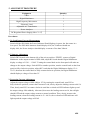
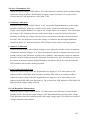
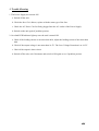
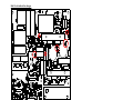
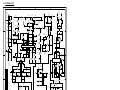
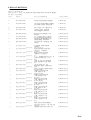
MANSON ENGINEERING INDUSTRIAL LTD.
SERVICE MANUAL
FOR
SPS-9400
CONTENTS
1. PRODUCTION SPECIFICATION
P.1
2. ALIGNMENT PROCEDURE
P.2
3. TROUBLE SHOOTING
P.5
4. CHANGE OF ELECTRONIC COMPONENTS
P.6
5. DIAGRAMS
P.8
5.1 SCHEMATICS
P.8
5.2 PCB SILKSCREEN
P.9
6. BILL OF MATERIAL
P.10
1. PRODUCTION SPECIFICATION
MODEL: SPS-9400-000
REV. 1.0
DATE: 24-8-2000
DESCRIPTION: 3-15V 40A SWITCHING MODE POWER SUPPLY
INPUT VOLTAGE: 207-245 VAC
FREQUENCY: 50 Hz
0
ENVIRONMENT TEMPERATURE: 25 C
Rated Output Voltage Range
Max. Output Voltage
Min. Output Voltage
Fixed Output Voltage
Output Current (continue)
Protection Current (start point)
Over Voltage Protection
Voltage Regulation:
Load (0~100% load)
Line (207~254Vac Varition)
Ripple & Noise (r.m.s)
Ripple & Noise (peak to peak)
No Load Input Current
Full Load Input Current
Power consumption at 15V
Insulation Resistance (500Vdc)
Withstanding Test (10mA 60s)
Power factor
Efficiency:
Loading 13.8V 40A
Loading 15V 40A
Meter Accuracy:
Voltmeter
Ammeter
Fuse
MIN.
3
15.1
TYP.
13.5
13.8
40
43.5
16.5
43
16
2
30
MAX.
15
16.1
3
14.3
44.5
17
UNIT
V
V
V
V
A
A
V
200
50
5
50
380
3.5
770
mV
mV
mV
mV
mA
A
W
100
2.1
97
78
79
MΩ
KV
%
80
82
%
%
±1%1+1
±1%1+1
5
REMARKS:
1. Rated load is 15V 40A.
2. Insulation resistance is measured as INPUT vs. HOUSING.
3. High frequency interference test (sample 3%).
Test frequency : 1. 437 MHz (5W) 2. 144 MHz (5W)
Result
: No function have been affected. Output Voltage
Dight
Dight
A
0.5V Variation.
P.1
2. ALIGNMENT PROCEDURE
Equipment
Quantity
CRO
1
Digital Multimeter
1
High Frequency Micrometer
1
Electronic Load
1
Adjustable AC Transformer
1
Power Analyzer
1
DC Regulated Power Supply (Max. V>17)
1
Procedures:
1. No Load Input Current Measurement
Switch ON the SPS-9400, the Power Indicator Should light up in green, the fan rotates in a
low speed. The SPS-9400 Ammeter should display 00.0, the Voltmeter should not
display 00.0, the Power Analyzer should display a current of less than 380mA.
2. Voltmeter Adjustment
Switch SW2 located at the bottom side of the unit to position “FIXED”, connect a Digital
Multimeter to the output terminal of SPS-9400, adjust RV4 such that the Digital Multimeter
display a voltage of 13.81 ~ 13.84V. Turning the control knob on the front panel will make no
change to the output voltage. Switch SW2 to another position, turn the control knob on the front
panel to fully-clockwise position, adjust RV2 such that the Digital Multimeter display 15.4 ~
15.6V, then turn the control knob to fully-counterclockwise position, the Digital Multimeter
should display a voltage of less than 3V.
3. Protection Current Adjustment
Adjust the output voltage of SPS-9400 to 15V by turning the control knob, turn RV3 to
fully-clockwise position, connect the Electronic Load, slowly adjust the loading current to 44.5A.
Then, slowly turn RV3 in counter-clockwise until the overload red LED indicator lights up and
the output voltage falls suddenly. Afterward, decreases the loading current to 0A, the red light
should OFF and the output voltage returns to normal condition. Then, slowly increases the
loading current, when the loading current is 43 ~ 44.5A, the overload red LED indicator will
light up and the output voltage will fall.
P.1
P.2
4. Power Consumption Test
Adjust the output voltage of SPS-9400 to 15V and connect the electronic load with 40A loading
current, the Power Analyzer should display an input current of less than 3.5A, power factor
of more than 0.97 and input power of less than 770W.
5. Voltmeter Calibration
Adjust the output voltage of SPS-9400 to 15.0V, connect the Digital Multimeter to the output
terminal of SPS-9400, adjust the variable resistor on the Voltmeter such that the voltage
display on the Digital Multimeter is equal to the voltage display on Voltmeter. Then, check that
the voltage on the Voltmeter increases as the control knob is turned in clockwise direction.
Similarly, check that the voltage decreases as the control knob is turned in counterclockwise
direction. Also, the difference between the voltage on Voltmeter and the Digital Multimeter
should less than 0.2V. And check that the LED Voltmeter does not have missing segment.
6. Ammeter Calibration
Connect the Electronic Load with 40A loading current, adjust the variable resistor of Ammeter
such that the Ammeter displays 39.9. Then, check that the current on Ammeter increases as the
loading current on the Electronic Load increases. Similarly, check that the current on Ammeter
decreases as the loading current on the Electronic Load decreases. Also, the difference between
the current on Ammeter and the Digital Multimeter should less than 0.4A. And check that the
LED Ammeter does not have missing segment.
7. Over-Voltage Protection Test
Adjust the output voltage of the DC Regulated Power Supply to 15.9V and connect to the
output terminal of SPS-9400, then disconnect it and the SPS-9400 is in working condition.
Adjust the output voltage of the DC Regulated Power Supply to 16.9V and connect to the
output terminal SPS-9400, then disconnect it. The overload red LED indicator of SPS-9400 will
light up and the output voltage will fall.
8. Load Regulation Measurement
Adjust the output voltage of SPS-9400 to 15V and connect to the Electronic Load with 40A
loading current, measure the output voltage by the Digital Multimeter and record the voltage.
Then, disconnect from the load and measure the output voltage again. The difference between 2
voltages should less than 200mV.
P.3
9. Ripple and Noise Measurement
Adjust the output voltage of SPS-9400 to 15V and connect to the Electronic Load with 40A
loading current. Measure the output terminal by the High Frequency Micrometer and the value
should less than 5mV. Connect the output terminal to CRO and the Peak to Peak measured
wave form should less than 50mVp-p.
10. Line Regulation Measurement
Adjust the output voltage of SPS-9400 to 15V and connect to the Electronic Load with 40A
loading current. Adjust the input voltage to 190V and 254V, record the output voltage at these 2
input voltages, the difference between these 2 output voltages should less than 50mV.
11. Loading Test
Adjust the output voltage of SPS-9400 to 15V and connect to the Electronic Load with 40A
loading current, turn OFF the SPS-9400. Then, make sure the Electronic Load has a 40A loading
current, turn ON SPS-9400 again and check that the SPS-9400 is ON and the Overload Indicator
is OFF.
Remarks:
1. The above procedures should be carried out in normal condition, if the SPS-9400 has abnormal
condition (e.g. Unpleasant noise, smell , smoke, etc...), turns OFF the AC source at once.
P.1
P.4
3. Trouble Shooting
1. The Power Supply do not turn ON.
a. Switch off the unit.
b. Check the fuse if it is blown, replace with the same type of the fuse.
c. Check the AC Power Cord is firmly plugged into the AC socket of the Power Supply.
d. Switch on the unit again if problem persists.
2. Overload LED Indicator light up once the unit is turned ON.
a. Check if the loading current is not more than 40A, adjust the loading current of not more than
40A
b. Check if the output voltage is not more than 16.5V. The Over Voltage Protection is at 16.5V.
c. Check if the output is short circuit.
d. Switch off the unit, wait 30 minutes and switch it ON again to see if problem persists.
P.1
P.5
4. CHANGE OF ELECTRONIC COMPONENTS (Fig.1)
Name of Component
Position
1
Electrolytic Capacitor
2
Auxiliary Transformer TR2
3
Fast Recovery Diode
4
Metal Film Resistor
5
Carbon Film Resistor
Before
changes
C10,C11 680uF/200V
After changes
Date of
Change
680uF/250V
14/09/01
0.23mm/96T
0.15mm/136T
18/09/01
D2
MUR880
MUR860
18/01/02
R9
1.3Mohm
620K1/4W + 1% &
28/02/02
1/4W + 1%
680K1/4W + 1% in series
470kohm
240kohm1/4W + 5%&
1/4W + 5%
240kohm 1/4W + 5% in series
R13
28/02/02
Reason of Changes:
1. The voltage of 680uF/200V Electrolytic Capacitor is too low.
2. The 0.23mm/96T Auxiliary Transformer does not match to our design of the SPS-9400.
3. When using MUR860, the voltage drop across the diode decreases, thus its temperature is
lower.
4. The wattage of the Metal Film Resistor 1.3Mohm 1/4W + 1% is too low.
5. The wattage of the Carbon Film Resistor 470kohm 1/4W + 5% is too low.
P.6
Red Circle indicate the changes
Fig.1
P.7
5.1 SCHEMATICS
D
C
B
A
SW1
12A
AC FILTER R5
470K
OUTPUT
SW1
12A
L2
100UH
C1
1UF/275VAC
L3
100UH
R29
1.8K
R35
1M
OUT1
12
D11
4148
5
6
L1
6.0MH
7
C2
0.1/275VAC
U3B
2
BR1
10G4B
C5
3.3/400V
LED1
Q4
C1815
VCC
R23
1.5K
C3
3.3/400V
R22
100
R26
22K
R27
100K
1
15
16
4
3
11
12
13
7
9
10
U5
TL494
8
6
5
14
2
R40
56k
RED
C22
10UF/50V Q5
C1815
D8
4148
C4
0.0033/250VAC
2
VREF
R33
4.7K
R38
330K
R46
47K
2
275VAC
C80
0.1UF
0.7MH
L7
C33
10UF/50V
15K 1%
R42
C30 1000PF
C29
0.33
R37
33K
C26
1000PF
D12
4148
C32
0.01
R100
680K
VREF
R43 3K
C51 0.33
U4A
4069
C21
1000PF
9
10
R32
1K
1
LM324
C20
1000
R25
1M
R31
220K
C28
0.33
R39
560
U4E
4069
U4D
4069
NTC1
C79 20S100L
1UF
275VAC
AC LINE FILTER
R101
680K
8
11
R36
4.7K
R21
56K
R45
4.7K
OUTPUT<+>
C27
1UF
50V
R30
10K
OUTPUT"+"
RV4
1K
R20
10K
R19
10K
1
13
F1 5A
MOV
Over Voltage Protetion
U4F
4069
ZD3
13V/ 1W
R41
150
R34
510
S2
R001
39K
C19
10UF/50V
VCC
R18
3.9K
C18
10UF/50V
VREF
R28
2K
RV1
10K
RV2
5K
R44
470
INPUT
190-254VAC 50HZ
1
C6
0.01
R1
1.3M
1%
8
R3
100K/1W
3
R2
12K
1%
6
U1
MC34262
2
C7
1UF/50V
R24
1.5K
6
D9
4148
RV3
5K
R48
47K
R49
10K
VCC
1
Q6
C2120
Q7
A950
C001
1000/1KV
R50
330
R47
1K
U4C
4069
LED2
GREEN
C23
0.1
5
C24
10UF/50V
C25
0.1
VREF
1UF
C31
VCC
R51
330
Q8
C2120
Q9
A950
C81
3300PF/250VAC
C82
3300PF 250VAC
5
7
4
1
U3A
LM324
TR1
BOOST
Q2
FP460
3
2
L=140UH
D2 MUR860
680K
1%
620K
1%
R9
R10
8.5k
1%
Q13
FP460
Q12
FP460
R82
47K
C72
4700
VREF
C34
10UF/50V
R55
10
R8
0.1/2W
VCC
C35
1000
R54
470
D13
4148
ZD4
15V
R60
10
D14
4148
ZD5
15V
4
R11
C10
680UF 100K/1W
250V
240K
R13
TR2
AUX PS
ZD1
200V/1W
C16
0.1
C
UF4005
D3
D
S
R87
2.2K
R85
560
R14
15K
U2
TOP222Y
R86
22K
C37
0.1
5
D5 RGP10G
L4 3.3UH
C13
470UF/25V
R16
18
ZD2
6.2V
Q3
A950
R17
1K
VCC
6
C62
C61
0.1UF 100UF
25V
REVISION: 1.6
+
-
DM VDD
C12
0.01uF/500V
C56
1000 R68
1KV 330/1W
OUTPUT<+>
OUTPUT<->
OUTPUT<+>
R92
PG-103J
R74
0.1
C39
0.01
C14
220UF/25V
R91
15K
C55
0.01
R73
0.1
R90
56K
C53
C52
C54
1000UF 1000UF 0.22
R72
0.1
R89
9.1K
D7
4148
1UF/50V
C15
D6 4148
C71 2200/100V
R15
6.8
9
10
C17 47UF/16V
U3C
LM324
8
R88
390K
R71
0.1
R80
0.1
VREF
M2
A
R70
0.1
R79
0.1
M1
V
R69
0.1
R78
0.1
1
*
R77
0.1
OF
C59
C60
100UF 0.01
25V
R76
0.1
C58
0.1UF
R75
0.1
C38 1UF/50V
L6
0.5UH/40A
out 1
L5
14UH/40A
C57
0.01
C50
4700UF/25V
C47
4700
C49
0.22
C43
4700
FAN
Q14
A950
VCC
C70
0.022/630V 240K
R84
47/3W
D16A
C45
3300
C46
3300
D15B
20DL2C
D15A
C44
3300
R66
15/1W
C36
220UF/25V
C11 R12
680UF 100K/1W
250V
R83
2.4K
TR4
M.TR
C41
3.3UF/250V
R65
47/3W
C42
1000/1KV
20DL2C
D16B
C48
3300
R67
15/1W
1
6
MANSON ENGINEERING INDUSTRIAL LTD.
DATE: 14-05-2002
SHEET
A
B
C
D
P.8
3
D1
4148
C8 100UF/50V
R52
5.6
D10
4148
R53
470
R56
5.6
Q10
A950
R59
470
R61
5.6
Q11
A950
C73
4700
NOTE : ALL RESISTORS ARE IN OHM&1/4W UNLESS SPECIFIED
DWG.NO. :
5
9800-9400-0000
TITLE :
4
APPROVED BY :
SPS-9400-000.SCH INPUT 190-254VAC
50HZ
CHECKED BY :
DRAWN BY :
R58
470
R81 1M
R6 330 R7
0.1/2W
R5B 10
R4 22K
Q1
R5A 10 FP460
C9
1000
TR3
DRIVER
OUTPUT
AC FILTER
3
4
11
5.2 PCB SILKSCREEN
P.9
6. BILL OF MATERIAL
Model #: SPS-9400-215
Description: 3-15Vdc, 40A SWITCHING MODE POWER SUPPLY W/DIGITAL METERS
Rev Date: 03/10/2002
Level
Code #
Description/Remarks
Usage U/M Op
-----------------------------------------------------------------------------------------0
8710-8400-0099
DRIVER TRANSFORMER ASSEMBLY
1.00000 SET
0
8710-8400-4099
SPS-8400 TRANSFORMER ASSEMBLY
FOR POWER FACTOR CONTOLLER
1.00000 PCS
0
8760-8400-0099
EMI FILTER 230V VERSION CE
1.00000 PCS
0
8761-4000-3099
OUTPUT FILTER INDUCTOR
SUB.ASSEMBLY 14UH/40A
1.00000 PCS
0
SPS-8400-PA-000
1
SPS-8400-000 MATERIAL FOR
PACKING
Q.C. PASSED LABEL 37X14mm
SILVER W/BLACK LETTERING
SPS-8400-000 MATERIAL FOR
TRANSFORMER (T8400000)
SPS-9400-000 MATERIAL FOR
CASING
7615-0900-0000
0
SPS-8400-TR-000
0
SPS-9400-CA-000
1
3113-0460-1303
1
3232-0020-9242
1
3601-2751-1301
1
3631-1045-0019
1
3675-0502-1602
1
4021-0204-5038
1
4199-9400-9903
2
0513-1006-0611
2
0513-4702-0611
2
0522-1005-0411
2
0522-1505-0411
2
0522-2003-0411
2
0522-4705-0411
2
0522-5606-0411
2
0522-7503-0411
Location :
Location :
Location :
Location :
Location :
Location :
Location :
Location :
Location :
Location :
Location :
Location :
Location :
Location :
2
0685-2224-1110
2
1011-1023-0171
Location :
1.00000 SET PA
1.00000 PCS PA
1.00000 SET TR
1.00000 SET CA
N-CHANNEL POWER MOSFET
IRFP460
Q12,Q13,Q1,Q2.
FAST RECOVERY RECTIFIER
20DL2C41 "TOSHIBA"
D15,D16.
METAL OXIDE VARISTOR
"HARRIS" V275LA20A
Z1,
F.Y.I. THERMISTOR NTC 10K AT
25DEG B=3720K DIA. 1.85
R92
FUSE 5A 250V VDE APPROVAL
20mm STANDARD GLASS TUBE
F1
LED EL204GD DIA. 3mm
DIFFUSED GREEN "EVERLIGHT"
LED2.
DUAL LED PANEL METER MODULE
FOR SPS-9400
CARBON FILM RESISTOR
1/4W 1Mohm +/-5%
R4,R5,R12,R13.
CARBON FILM RESISTOR
1/4W 470ohm +/-5%
R19,R20.
METAL FILM RESISTOR
1/4W 100Kohm +/-1%
R1,R10,R6,R7.
METAL FILM RESISTOR
1/4W 150Kohm +/-1%
R14,R15.
METAL FILM RESISTOR
1/4W 2Kohm +/-1%
R16,R17.
METAL FILM RESISTOR
1/4W 470Kohm +/-1%
R3,R18.
METAL FILM RESISTOR
1/4W 5.6Mohm +/-1%
R8,R9.
METAL FILM RESISTOR
1/4W 7.5Kohm +/-1%
R11
4.00000 PCS CA
SEMI-FIXED POTENTIOMETER
SCR-065A 22K(B)+/- 25% DIA.6mm
VR1,VR2.
CERAMIC CAPACITOR 100PF 50V
2.00000 PCS IN
2.00000 PCS CA
1.00000 PCS CA
1.00000 PCS CA
1.00000 PCS CA
1.00000 PCS CA
1.00000 SET CA
4.00000 PCS IN
2.00000 PCS IN
4.00000 PCS IN
2.00000 PCS IN
2.00000 PCS IN
2.00000 PCS IN
2.00000 PCS IN
1.00000 PCS IN
2.00000 PCS IN
P.10
2
1011-1041-0171
2
1011-1051-0151
2
1011-1523-0171
2
1021-2272-0151
2
1021-2282-0131
2
1021-4782-3142
2
1028-4762-0171
2
1062-1054-0181
2
1062-2253-0181
2
1062-4743-0181
2
2531-7805-3068
2
2544-7107-0131
Location :
Location :
Location :
Location :
Location :
Location :
Location :
Location :
Location :
Location :
Location :
Location :
Location :
2
2581-4069-0001
2
3201-4148-9002
2
3232-0010-9482
2
3679-0101-2002
2
4021-0204-2038
2
4157-1056-0601
2
4510-3030-5041
2
4543-3030-6042
2
6701-0202-0000
2
7050-0208-2911
2
7054-4099-2012
2
7055-0413-2017
2
7055-2156-2017
2
7204-3008-1001
2
7304-3006-0900
Location :
Location :
Location :
Location :
Location :
Location :
Location :
Location :
Location :
Location :
+/-10%
C11,C18.
CERAMIC CAPACITOR 0.01UF 50V
+80%/-20%
C10,C12.
CERAMIC CAPACITOR 0.1UF 25V
+80%/-20%
C2,C3.
CERAMIC CAPACITOR 150PF 50V
+/-10%
C16,C17.
ELECT. CAPACITOR 22UF 25V
+/-20% DIM. 5 X 11 MM
C6.
ELECT. CAPACITOR 220UF 10V
+/-20% DIM. 6 X 12 MM
C4.
ELECT. CAPACITOR 470UF 16V
+/-20% DIM. 8X12mm PITCH 3.5mm
C1.
NON-POLAR ELECT.CAPACITOR 85c
4.7uF 50V +/-20% DIM.5X11mm
C5
METALLIZED POLYESTER CAP
0.1UF 63VDC +/-5% BOX TYPE
C9,C15.
METALLIZED POLYESTER CAP
0.22UF 63VDC +/-10% BOX TYPE
C8,C14.
METALLIZED POLYESTER CAP
0.047UF 63VDC +/-10% BOX TYPE
C7,C13.
IC 7805CV "SGS" POSITIVE DC
VOLTAGE REGULATORS
U2.
IC ICL7107CPL 31/2 Digits A/D
W/LED Display "INTERSIL"
U3,U4
IC 4069UB CMOS HEX INVERTER
U1.
Si SIGNAL DIODE 1N4148 TNR
D5,D6.
FAST RECOVERY RECTIFIER
400V/1A RGP10G "FAGOR"
MICRO FUSE 1A 125V
FAST ACTING TYPE W/UL&CSA
LED EL204HD DIA. 3mm
DIFFUSED RED "EVERLIGHT"
CV.
SEVEN SEGMENTS LED DISPLAY
WNDA1056GHB 0.56" GREEN
LED1-LED6
MPD-DUAL LED PANEL METER A/D
PCB 94VO REV.0 (TECHCOM)
MPD DUAL LED PANEL METER PCB
FR4 94V0 DS PTH (TECHCOM)
HEAT SINK TO-202
HS
2 PIN SHROUDED HEADER (180)
M241852 "STM" TOP ENTRY TYPE
JP1
PIN HEADER CONNECTOR 1X40 PIN
WAFER P=2.54mm PHB1-S40S-G01
CN1,CN2,CN3.
FEMALE HEADER 4 PIN
PHTCH:2.54mm 2212CS-04T
CN3
FEMALE HEADER 21 PIN
PHTCH:2.54mm 2212CS-21T
CN1,CN2.
SCREW M3X8X0.5 W/Ni PLATING
PAN HEAD CROSS DRIVER
7805
EXTERNAL TOOTH WASHER M3X6X0.9
2.00000 PCS IN
3.00000 PCS IN
2.00000 PCS IN
1.00000 PCS IN
1.00000 PCS IN
1.00000 PCS IN
1.00000 PCS IN
2.00000 PCS IN
2.00000 PCS IN
2.00000 PCS IN
1.00000 PCS IN
2.00000 PCS IN
1.00000 PCS IN
2.00000 PCS IN
1.00000 PCS IN
1.00000 PCS IN
1.00000 PCS IN
6.00000 PCS CA
1.00000 PCS IN
1.00000 PCS IN
1.00000 PCS IN
1.00000 PCS IN
1.15000 PCS IN
1.00000 PCS IN
2.00000 PCS IN
1.00000 PCS IN
1.00000 PCS IN
P.11
2
7350-3005-2341
STEEL NUT M3X0.5
1.00000 PCS IN
1
4801-2106-6506
1.00000 PCS CA
1
6201-9400-0000
ROCKER SWITCH M372-399-2R3
2P1T W/RED DOT
PLASTIC FRONT PANEL SPS-9400
WARM GREY 1C W/EMI SHIELDING
PLASTIC FRONT PANEL SPS-8400
WARM GREY 1C (NO BAND NAME) PC
LENS 101X35X1mm THK PVC
TRANSPARENT BROWN EPD-9300
FRONT
PLASTIC VOLUME KNOB SPS-8400
WARM GREY 1C
PC
PLASTIC SPACER FOR MPD METER
DIA. 6x11mm I.D.=3.5mm
HEAT SINK FOR GZV2500 W=68
H=10 L=65mm W/M3X0.5 (X4)
Q12,Q13
HEAT SINK FOR GZV4000 W=65
H=20 10FIN L=76mm
D15,D16.
HEAT SINK FOR SPS-8400 W=68,
H=10, L=75mm
Q1,Q2.
SPS-9400-000 MATERIALS FOR
INSERTION
CARBON FILM RESISTOR
1/4W 10ohm +/-5%
R55,R60,R5A,R5B.
CARBON FILM RESISTOR
1/4W 100ohm +/-5%
R22.
CARBON FILM RESISTOR
1/4W 1Kohm +/-5%
R17,R32,R47.
CARBON FILM RESISTOR
1/4W 10Kohm +/-5%
R19,R20,R30,R49.
CARBON FILM RESISTOR
1/4W 100Kohm +/-5%
R27
CARBON FILM RESISTOR
1/4W 1Mohm +/-5%
R25,R35,R81.
CARBON FILM RESISTOR
1/4W 150ohm +/-5%
R41
CARBON FILM RESISTOR
1/4W 1.5Kohm +/-5%
R23,R24.
CARBON FILM RESISTOR
1/4W 15Kohm +/-5%
R14,R91.
CARBON FILM RESISTOR
1/4W 18ohm +/-5%
R16
CARBON FILM RESISTOR
1/4W 1.8Kohm +/-5%
R29.
CARBON FILM RESISTOR
1/4W 2Kohm +/-5%
R28
CARBON FILM RESISTOR
1/4W 2.2Kohm +/-5%
R87.
CARBON FILM RESISTOR
1/4W 22Kohm +/-5%
R4,R26,R86.
CARBON FILM RESISTOR
1/4W 220Kohm +/-5%
R31.
CARBON FILM RESISTOR
1/4W 2.4Kohm +/-5%
R83.
CARBON FILM RESISTOR
2
6201-8400-0011
1
6272-9300-0000
1
6281-8400-0000
1
6290-3030-0000
1
6701-2500-5010
1
6701-4000-5010
1
6701-8400-0000
Location :
Location :
Location :
Location :
0
SPS-9400-IN-000
1
0513-1001-0611
1
0513-1002-0611
1
0513-1003-0611
1
0513-1004-0611
1
0513-1005-0611
1
0513-1006-0611
1
0513-1502-0611
1
0513-1503-0611
1
0513-1504-0611
1
0513-1801-0611
1
0513-1803-0611
1
0513-2003-0611
1
0513-2203-0611
1
0513-2204-0611
1
0513-2205-0611
1
0513-2403-0611
1
0513-2405-0611
Location :
Location :
Location :
Location :
Location :
Location :
Location :
Location :
Location :
Location :
Location :
Location :
Location :
Location :
Location :
Location :
1.00000 PCS CA
1.00000 PCS CA
1.00000 PCS CA
1.00000 PCS CA
2.00000 PCS CA
1.00000 PCS CA
1.00000 PCS CA
1.00000 PCS CA
1.00000 SET IN
4.00000 PCS IN
1.00000 PCS IN
3.00000 PCS IN
4.00000 PCS IN
1.00000 PCS IN
3.00000 PCS IN
1.00000 PCS IN
2.00000 PCS IN
2.00000 PCS IN
1.00000 PCS IN
1.00000 PCS IN
1.00000 PCS IN
1.00000 PCS IN
3.00000 PCS IN
1.00000 PCS IN
1.00000 PCS IN
2.00000 PCS IN
P.12
1
0513-3003-0611
1
0513-3302-0611
1
0513-3304-0611
1
0513-3305-0611
1
0513-3903-0611
1
0513-3905-0611
1
0513-4702-0611
1
0513-4703-0611
1
0513-4704-0611
1
0513-4705-0611
1
0513-5102-0611
1
0513-5600-0611
1
0513-5602-0611
1
0513-5604-0611
1
0513-6800-0611
1
0513-6805-0611
1
0513-9103-0611
1
0515-3302-0611
1
0522-1204-0411
1
0522-1306-0411
1
0522-1504-0411
1
0522-6205-0411
1
0522-6805-0411
1
0522-8503-0411
1
0525-0100-0411
Location :
Location :
Location :
Location :
Location :
Location :
Location :
Location :
Location :
Location :
Location :
Location :
Location :
Location :
Location :
Location :
Location :
Location :
Location :
Location :
Location :
Location :
Location :
Location :
Location :
1/4W 240Kohm +/-5%
R13
CARBON FILM RESISTOR
1/4W 3Kohm +/-5%
R43.
CARBON FILM RESISTOR
1/4W 330ohm +/-5%
R6,R50,R51
CARBON FILM RESISTOR
1/4W 33Kohm +/-5%
R37.
CARBON FILM RESISTOR
1/4W 330Kohm +/-5%
R38.
CARBON FILM RESISTOR
1/4W 3.9Kohm +/-5%
R83.
CARBON FILM RESISTOR
1/4W 390Kohm +/-5%
R88.
CARBON FILM RESISTOR
1/4W 470ohm +/-5%
R44,R54,R53,R58,R59
CARBON FILM RESISTOR
1/4W 4.7Kohm +/-5%
R33,R36,R45.
CARBON FILM RESISTOR
1/4W 47Kohm +/-5%
R46,R48,R82.
CARBON FILM RESISTOR
1/4W 470Kohm +/-5%
R5
CARBON FILM RESISTOR
1/4W 510ohm +/-5%
R34.
CARBON FILM RESISTOR
1/4W 5.6ohm +/-5%
R56,R61,R52.
CARBON FILM RESISTOR
1/4W 560ohm +/-5%
R39,R85.
CARBON FILM RESISTOR
1/4W 56Kohm +/-5%
R21,R90,R40,R001.
CARBON FILM RESISTOR
1/4W 6.8ohm +/-5%
R15
CARBON FILM RESISTOR
1/4W 680Kohm +/-5%
R100
CARBON FILM RESISTOR
1/4W 9.1Kohm +/-5%
R89
CARBON FILM RESISTOR
1W 330ohm +/-5%
R68
METAL FILM RESISTOR
1/4W 12Kohm +/-1%
R2
METAL FILM RESISTOR
1/4W 1.3Mohm +/-1%
R1.
METAL FILM RESISTOR
1/4W 15Kohm +/-1%
R42.
METAL FILM RESISTOR
1/4W 620Kohm +/-1%
R9
METAL FILM RESISTOR
1/4W 680Kohm +/-1%
R9
METAL FILM RESISTOR 1/4W
8.5Kohm +/-1%
R10
METAL FILM RESISTOR 0.1ohm 2W
1.00000 PCS IN
3.00000 PCS IN
1.00000 PCS IN
1.00000 PCS IN
1.00000 PCS IN
1.00000 PCS IN
5.00000 PCS IN
3.00000 PCS IN
3.00000 PCS IN
1.00000 PCS IN
1.00000 PCS IN
3.00000 PCS IN
2.00000 PCS IN
4.00000 PCS IN
1.00000 PCS IN
1.00000 PCS IN
1.00000 PCS IN
1.00000 PCS IN
1.00000 PCS IN
1.00000 PCS IN
1.00000 PCS IN
1.00000 PCS IN
1.00000 PCS IN
1.00000 PCS IN
14.00000 PCS IN
P.13
1
0534-1005-0611
1
0534-1501-0611
1
0536-4701-0611
1
0600-2103-4010
1
0685-2103-1110
1
0685-2503-1110
1
1011-1031-0171
1
1011-1032-0291
1
1011-1041-0171
1
1011-1042-1261
1
1011-1051-0171
1
1011-2231-0191
1
1011-4731-0171
1
1021-1062-0171
1
1021-1072-0171
1
1021-1082-0151
1
1021-1082-0171
1
1021-2282-0151
1
1021-4772-0141
1
1021-4782-0151
1
1022-1032-0151
1
1022-4732-0311
1
1022-6882-4231
1
1028-3352-0171
1
1035-1053-0241
Location :
Location :
Location :
Location :
Location :
Location :
Location :
Location :
Location :
Location :
Location :
Location :
Location :
Location :
Location :
Location :
Location :
Location :
Location :
Location :
Location :
Location :
Location :
Location :
Location :
+/-5%
R7,R8,R69-R80
METAL OXIDE RESISTOR 100Kohm
1W +/-5%
R3,R11,R12
METAL OXIDE RESISTOR 15ohm 1W
R66,R67.
METAL OXIDE RESISTOR 47ohm
3W +/-5% WIRE LENGTH=30mm
R65,R84.
VARIABLE RESISTOR 10K CURVE B
CTS 296UD103B1N +/-20%
VR1
SEMI-FIXED POTENTIOMETER
SCR-065A 1K(B) +/- 25% DIA.6mm
RV4
SEMI-FIXED POTENTIOMETER
SCR-065A 5K(B) +/- 25% DIA.6mm
RV2,RV3.
CERAMIC CAPACITOR 0.001UF 50V
+80%/-20%
C9,C20,C21,C35.
CERAMIC CAPACITOR 1000PF 1KV
+/-20%
C42,C56,Q6->Q8.
CERAMIC CAPACITOR 0.01UF 50V
+80%/-20%
C6,C32,C39,C55,C57,C60.
CERAMIC CAPACITOR 0.01UF 500V
+80%/-20%
C12
CERAMIC CAPACITOR 0.1UF 50V
+80%/-20%
C16,C23,C25,C37,C58,C61.
CERAMIC CAPACITOR 2200PF 100V
+80%/-20%
C71
CERAMIC CAPACITOR 0.0047uF 50V
+80%/-20%
C43,C47.
ELECT. CAPACITOR 1UF 50V
+/-20% DIM. 5 X 11 MM
C7,C15,C27,C38.
ELECT. CAPACITOR 10UF 50V
+/-20% DIM. 5 X 11 MM
C18,C19,C22,C24,C33,C34.
ELECT. CAPACITOR 100UF 25V
+/-20% DIM. 6.3 X 11 MM
C59,C62.
ELECT. CAPACITOR 100UF 50V
+/-20% DIM. 8 X 11.5MM
C8
ELECT. CAPACITOR 220UF 25V
+/-20% DIM. 8 X 11.5 MM
C14,C36
ELECT. CAPACITOR 47UF 16V
+/-20% DIM. 5 X 11 MM
C17
ELECT. CAPACITOR 470UF 25V
+/-20% DIM. 10 X 12.5 MM
C13
ELECT. CAPACITOR 1000UF 25V
+/-20% DIM. 10 X 20 MM
C52,C53
ELECT. CAPACITOR 4700UF 25V
+/-20% 105 C DIM. 16 X 35.5 MM
C50
ELECT. CAPACITOR 680UF 250V
85C +/-20% 22X56mm LP SERIES
C10,C11
NON-POLAD ELECT CAPACITOR
0.33uF 50V +/-20% DIM 5X11mm
C28,C29,C51.
METALLIZED CAPACITOR
0.1UF 275VAC X2
3.00000 PCS IN
2.00000 PCS IN
2.00000 PCS IN
1.00000 PCS IN
1.00000 PCS IN
2.00000 PCS IN
4.00000 PCS IN
3.00000 PCS IN
6.00000 PCS IN
1.00000 PCS IN
6.00000 PCS IN
1.00000 PCS IN
2.00000 PCS IN
4.00000 PCS IN
6.00000 PCS IN
2.00000 PCS IN
1.00000 PCS IN
2.00000 PCS IN
1.00000 PCS IN
1.00000 PCS IN
2.00000 PCS IN
1.00000 PCS IN
2.00000 PCS IN
3.00000 PCS IN
1.00000 PCS IN
P.14
1
1035-1062-0241
1
1035-3333-4231
1
1061-2243-0271
1
1061-3363-0231
1
1061-3363-0251
1
1094-1033-0171
1
1094-2253-0191
1
1094-3333-0191
1
1094-4733-1191
1
1095-1062-1171
1
1501-5021-3312
1
2533-0222-0458
1
2533-0494-0210
1
2534-3262-0041
1
2541-0324-0061
1
2581-4069-0001
1
3010-2120-2401
1
3017-1815-0001
1
3023-0950-0001
1
3201-4148-9002
Location :
Location :
Location :
Location :
Location :
Location :
Location :
Location :
Location :
Location :
1
3222-0105-9510
1
3231-4005-9531
1
3231-6008-0007
1
3232-0010-9482
1
3261-1311-0002
1
3261-1511-0002
1
3261-2021-0042
Location :
Location :
Location :
Location :
Location :
Location :
Location :
Location :
Location :
Location :
Location :
Location :
Location :
Location :
Location :
Location :
Location :
C2.
METALLIZED CAPACITOR
1UF 275VAC X2
C1
CERAMIC CAP. 3300pF/250VAC
+/-10% PITCH=10mm Y2
C4B
METALLIZED POLYESTER CAP
0.022uF 630V +/-10%
C70.
METALLIZED POLYESTER CAP.
3.3uF 250V +/-10% (MEF)
C41
METALLIZED POLYESTER CAP.
3.3uf 400VDC +/-10% 31X18X9mm
C3,C5.
MYLAR CAPACITOR 0.001UF 50V
+/-10%
C26,C30.
MYLAR CAPACITOR 0.22UF 100V
+/-10%
C49,C54.
MYLAR CAPACITOR 0.0033UF 100V
+/-10%
C44,C45,C46,C48
MYLAR CAPACITOR 0.0047UF 100V
+/-10% PITCH=5mm
C72,C73.
MONO CAPACITOR 1UF / 50V
+/-20%
C31.
POWER INDUCTOR 3.3uH +/-20%
500mA 3R3M-A12X-BL-N
L4.
PWM SWITCH TOP222Y "TOPSWITCH"
U2
IC TL494CN "TI" PWM CONTROLLER
U5.
IC MC33262P "ON"
POWER FACTOR CONTROLLER
U1
IC LM324N "ST" LOW POWER QUAD
OP-AMP
U3.
IC 4069UB CMOS HEX INVERTER
U4.
NPN GENERAL PURPOSE TRANSISTOR
2SC2120Y "TOSHIBA" TO-92
Q6,Q8
NPN SMALL SIGNAL TRANSISTOR
2SC1815GR TO-92
Q4,Q5.
POWER PNP TRANSISTOR A950
"TOSHIBA"
Q3,Q7,Q9,Q10,Q11,Q14.
Si SIGNAL DIODE 1N4148 TNR
D1,D6-D14.
BRIDGE RECTIFIER SB105
600V/10A SB-10 "TS"
BR1
FAST RECOVERY RECTIFIER
600V/1A UF4005 "MCC" DO-41
D3
FAST RECOVERY DIODE MUR860
600V/8A TO-220AC
D2
FAST RECOVERY RECTIFIER
400V/1A RGP10G "FAGOR"
D5
ZENER DIODE 13V 1W TNR
ZD3.
ZENER DIODE 15V 1W TNR
"1N4744A"
ZD4,ZD5
ZENER DIODE 200V 1W TNR
2.00000 PCS IN
1.00000 PCS IN
1.00000 PCS IN
1.00000 PCS IN
2.00000 PCS IN
2.00000 PCS IN
2.00000 PCS IN
4.00000 PCS IN
2.00000 PCS IN
2.00000 PCS IN
1.00000 PCS IN
1.00000 PCS IN
1.00000 PCS IN
1.00000 PCS IN
1.00000 PCS IN
1.00000 PCS IN
2.00000 PCS IN
2.00000 PCS IN
6.00000 PCS IN
10.00000 PCS IN
1.00000 PCS IN
1.00000 PCS IN
1.00000 PCS IN
1.00000 PCS IN
1.00000 PCS IN
2.00000 PCS IN
1.00000 PCS IN
P.15
1
3261-6200-5311
1
3620-0605-3001
1
4351-2052-6215
1
4856-1205-1010
1
6701-0202-0000
1
6701-4000-0001
1
6890-0950-0001
1
6890-0950-0002
1
7040-0000-1214
1
7050-0312-4999
1
7122-2003-0170
1
7122-2004-0420
1
8710-9400-3199
1
8761-4000-0099
1
8761-4000-2099
1
8761-4000-4099
Location :
Location :
Location :
Location :
Location :
Location :
Location :
Location :
Location :
Location :
Location :
"ON" IN5956B
ZD1.
ROHM 0.5W ZENER 6.2V MTZJ6.2B
ZD1
NTC POWER THERMISTOR 6A 10ohm
at 25DEG. JNR20S100L "JOYIN"
PCB(C)
WIRE ASSEMBLY UL1007 #22 2 PIN
x205+4mm W/XH HOUSING
1.00000 PCS IN
1.00000 PCS IN
1.00000 PCS IN
SLIDE SWITCH SS-12F07B-G2 1P2T
0.5A 50V DC
S2.
HEAT SINK TO-202
D2
HEAT SINK FOR BRIDGE (SB-105)
25X25X2.0mm THK. ALUMINIUM
COPPER CONDUCTOR FOR ME-950
14mm(W)X54.5(L)X1.0mm THK.
CN1,CN2
COPPER CONDUCTOR FOR ME-950
14mm(W)X37.5(L)X1.0mm THK.W/Ni
CN3,CN4.
FASTON TAB TERMINAL 250
BRASS W/TIN PLATED P-850
PT1,PT2,PT3,PT4
3 PIN MOLEX PCB TYPE MALE
PITCH=3.96mm "5273 SERIES"
EYELET O.D. 1.7x3mm(L) BRASS
W/NICKEL PLATING
EYELET O.D. 4.2X4.5mm (L)
BRASS W/NICKEL PLATING
1.00000 PCS IN
SPS-9400 AUX TRANSFORMER
SUB-ASSEMBLY CE VERSION
TR2
OUTPUT FILTER INDUCTOR
0.5uH/40A
L6
COMMON MODE CHOKE COIL
ASSEMBRY 6MH X2
INPUT FILTER INDUCTOR
SUB.ASSEMBLY 100uH
L2,L3.
1.00000 PCS IN
1.00000 PCS IN
1.00000 PCS IN
2.00000 PCS IN
2.00000 PCS IN
4.00000 PCS IN
1.00000 PCS IN
3.00000 PCS IN
3.00000 PCS IN
1.00000 SET IN
1.00000 SET IN
2.00000 PCS IN
End