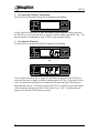
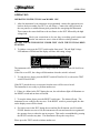
Download Models

Transcript
OPERATION AND SERVICE MANUAL
Model 1305, 2503, 2510, 2550
MODEL 1305 (AC ONLY HIPOT)
MODEL 2503 (DC ONLY HIPOT WITH OPTIONAL GROUND CONTINUITY CHECK)
MODEL 2510 (AC ONLY HIPOT WITH OPTIONAL GROUND CONTINUITY CHECK)
MODEL 2550 (AC/DC HIPOT WITH OPTIONAL GROUND CONTINUITY CHECK)
SERIAL NUMBER
Models
© Slaughter Company, Inc., 2007
28105 N. Keith Drive
Lake Forest, Illinois, 60045-4546
U.S.A.
1305/2503
2510/2550
Item 99-10136-01
Ver 1.07
Printed October 29, 2007
Warranty Policy
Slaughter Company, certifies that the instrument listed in this manual meets or exceeds
published manufacturing specifications. This instrument was calibrated using standards
that are traceable to the National Institute of Standards and Technology (NIST).
Your new instrument is warranted to be free from defects in workmanship and material for
a period of (1) year from date of shipment. You must return the “Owners Registration
Card”provided within (15) days from receipt of your instrument.
Slaughter Company recommends that your instrument be calibrated on a twelve-month
cycle. A return material authorization (RMA) must be obtained from Slaughter Company.
Please contact our Customer Support Center at 1-800-504-0055 to obtain an RMA
number. It is important that the instrument is packed in its original container for safe
transport. If the original container in not available please contact our customer support
center for proper instructions on packaging. Damages sustained as a result of improper
packaging will not be honored. Transportation costs for the return of the instrument for
warranty service must be prepaid by the customer. Slaughter Company will assume the
return freight costs when returning the instrument to the customer. The return method
will be at the discretion of Slaughter Company.
Except as provided herein, Slaughter Company makes no warranties to the purchaser of
this instrument and all other warranties, express or implied (including, without limitation,
merchantability or fitness for a particular purpose) are hereby excluded, disclaimed and
waived.
Any non-authorized modifications, tampering or physical damage will void your warranty.
Elimination of any connections in the earth grounding system or bypassing any safety
systems will void this warranty. This warranty does not cover batteries or accessories not
of Slaughter Company manufacture. Parts used must be parts that are recommended by
Slaughter Company as an acceptable specified part. Use of non-authorized parts in the
repair of this instrument will void the warranty.
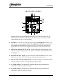
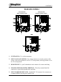
TABLE OF CONTENTS
INTRODUCTION .........................................................................................................2
INSTALLATION AND SAFETY ...................................................................................2
SERVICE AND MAINTENANCE .................................................................................9
GLOSSARY OF TERMS ...........................................................................................11
SPECIFICATIONS .....................................................................................................13
CONTROLS ................................................................................................................17
QUICK START...........................................................................................................21
SETUP .........................................................................................................................23
MODEL 1305 ...........................................................................................................23
MODELS 2503/2510/2550 ...........................................................................................26
FIELD INSTALLATION OF OPTIONS .......................................................................29
OPERATION...............................................................................................................30
MODEL 1305 ...........................................................................................................30
MODELS 2503/2510/2550 ...........................................................................................31
REMOTE INTERFACE FOR MODEL 1305 .................................................................33
REMOTE INTERFACE FOR MODELS 2503/2510/2550 ................................................34
OPTIONS ....................................................................................................................35
CALIBRATION PROCEDURE .................................................................................36
PARTS LIST ...............................................................................................................37
SCHEMATIC INDEX.................................................................................................38
INTRODUCTION
INTRODUCTION
This section is prepared to assist the user of Slaughter manually operated bench type test
equipment with the use, installation, inspection and maintenance of the equipment.
Since any electrical equipment can be hazardous, all procedures described should be
conducted by qualified personnel familiar with safety rules applying to electrical equipment
and who have been thoroughly instructed as to the nature of the procedure, the hazards
involved, and the necessary safety precautions.
Defects and weaknesses in the electrical insulation system must be detected to insure that
the product is safe for use by the consumer. In most windings there are two basic types of
insulation systems. The ground insulation separates the windings from a magnetic core
material or an exposed conductive frame or exterior. The second insulation system is the
wire insulation, which in lower voltage windings is typically a thin film coating the wire.
These two insulation systems perform different functions in the winding and require
different tests to evaluate their integrity. The Dielectric Withstand Test is used to
evaluate the ground insulation system.
This test has been described by many names; Hi-pot Test, Dielectric Withstand Test,
Insulation Leakage and Breakdown Test, Shorts Check, Ground Check and others. What
ever the name, the purpose is to detect failure of the insulation system that separates the
current carrying portions of an electrical device from any exposed conductive components.
For operator safety reasons, and to avoid possible tester damage,
the product under test SHOULD NOT BE CONNECTED in any
way to the AC power lines.
WARNING
Typically, it is the responsibility of the manufacturer to establish the proper tests needed
for a particular product to insure they comply with all agency requirements.
INSTALLATION AND SAFETY
For operator safety reasons, and to avoid possible tester
damage, the product under test SHOULD NOT BE
CONNECTED in any way to the AC power lines.
CAUTION
When first received, unpack the equipment carefully and inspect for any hidden damage.
If damage is evident, keep the carton and file a claim with the carrier.
Packed with all Slaughter equipment is a certificate of conformance, operator’s manual,
test leads and any required interface connectors.
2
INTRODUCTION
To check the unit quickly, install any interface connectors, plug the unit into the proper
voltage and follow the steps outlined under operating instructions.
If the unit does not operate, contact the factory for instructions.
Of prime consideration and importance in the layout and installation of a test station is to
insure the safety both to the operator and any visitors or casual bystanders, invited or
otherwise. As a general rule it is suggested that each test area be in a location with
minimum distractions and not subject to extremes of temperature and moisture.
One of the more important ways to promote safety is through operator training. Benefits
of training are twofold. First, thorough training promotes safety which may significantly
reduce injuries on the job. Second, it ensures adequate testing of the product which helps
increase product reliability. Both of these can have a positive impact on profits.
An additional consideration in any test station is operator comfort. This is affected by the
operator’s position, which includes the chair, table, test equipment, the object under test
and the test procedure itself. The chair and work bench or table should be nonconductive
and the table as large as possible to allow sufficient room for the test equipment and the
object under test. Studies should be made of the test requirements and work habits and
steps taken to ensure that any unusual or unnatural motion is not required and to eliminate
any repetitive motions that may produce injuries such as carpel tunnel syndrome.
After the equipment has been installed, a careful study should be made of the test station
to determine what, if any, safeguards are needed. It is suggested that any electrical test
station involving voltages in excess of 42.4 volts peak (approximately 30 volts RMS)
should be equipped with safeguards. These should operate both for the protection of the
operating personnel and for the protection of casual bystanders. At the minimum,
safeguards should prevent the operating personnel or casual bystanders from coming into
contact with the test circuit. In the event electrical interlocks of any sort are required,
either to insure that guards are in place, or to insure that the operator’s hands are in a safe
location, the installer should refer to the proper schematic drawing and install these
interlocks in series with the external interlock terminals provided in the tester. All testers
may be safety interlocked with series manual or automatic safety switches, relays, etc. as
desired. In the simpler units, this is done by inserting such interlocks in the AC supply
ahead of the tester. In some units adapter plugs with remote interface controls are
provided for this purpose. We will be happy to provide suggestions and schematics for
safety interlocking our test equipment.
Any electrical power receptacle utilized to operate this equipment must be a properly
grounded three wire receptacle that has been checked for proper polarity.
The test procedure should be well thought out to ensure that it adequately tests the
product to the desired criteria but, that the procedure does not require the operator to
perform tasks that are unsafe. The product should never be touched during a test and in
3
INTRODUCTION
the case of a grounded part the conductive table or conveyor should not be touched
during a test.
Several models of high voltage test equipment are designed with the high voltage output
“floating”. There is no ground on either the High side or the Low side of the high voltage
transformer. One of the test leads of the HV transformer is considered the Low side due
to the winding pattern of the transformer, but it is NOT grounded. This arrangement
provides a one type of safety margin to the operator because someone must come in
contact with both leads to receive a shock.
Some models of test equipment have one lead of the output grounded or production
requirements are such that it is impossible or impractical to test a product in an
“ungrounded” configuration. When the tester and the product are grounded, it is
important to remember that the operator is also grounded and need only touch the
ungrounded lead to receive a shock.
A major consideration in testing products that are “grounded” (touching a conductive
conveyor or table) is to insure that the operator or bystanders cannot or will not come in
contact with the table or conveyor during a test. Under some product failure conditions,
the table or conveyor may become “live”and present a high voltage potential to true earth
ground if the table or conveyor is not properly grounded.
It should never be assumed that a conveyor or conductive table is “grounded”just because
it is bolted to the floor. A proper ground is one that has been verified to return to the
input power line ground (earth ground) with a resistance of less than ½ ohm. This will
help eliminate “floating” grounds, ground loops and “phantom” voltages between the
object under test and the tester case which is grounded to the power line ground.
The testing of very large items such as recreational vehicles and mobile homes poses
special problems because the safety hazards involved are considerably greater than those
involved in testing smaller objects.
This is because it is possible under fault conditions for the entire outer skin of the object
being tested to become charged to a high voltage. This is particularly bad because these
units are so large that the person conducting the test is in no position to observe whether
or not any other people are in a potentially dangerous position during the test.
If proper precautions are taken, there will be no hazard, but even so, it is highly desirable
that care be taken to isolate the test object when a test is being conducted. Suggested
methods of doing this are the use of rope barriers, warning signs, and fully enclosed test
areas.
Before conducting a test on these units, care should be taken to see that the frame and
skin of the unit are connected to a solid ground, and also that the ground conductor of the
electrical system is connected to a solid ground. This will eliminate most test hazards, but
4
INTRODUCTION
bear in mind it is possible for some sections of the skin to have poor electrical connection
and that they thereby, can become a potential safety hazard in the event of a fault. This is
why isolation of the vehicle during the test is recommended.
Once these safety precautions have been taken and it has been established that the frame
and skin are properly grounded, the operator can proceed with the dielectric test.
Good safety practice dictates labeling of hazards properly. Since high voltage testing can
be hazardous, the work station should be labeled. Naturally, the location of the label
should be carefully selected so that it can be placed in a location that will do the most
good.
In some cases, this may be on the test instrument itself, and in others, it may be in a
location directly in front of the operator, somewhat removed from the instrument.
A final word about high voltage testers. Generally, commercial high voltage test
equipment is not in itself hazardous. The hazards come about when the equipment is
improperly used. These testers, when used properly and in a safe manner, can be a check
on the quality and reliability of your product. If used incorrectly and without proper
consideration for safety, they represent a hazard for both operating personnel and casual
bystanders. We strongly recommend proper training for all personnel involved in testing.
High Voltage Testing
High Voltage Testing has historically been the most mis-understood, mis-applied, misinterpreted inspection function in the average factory. Some manufacturers have looked
upon the High Voltage Dielectric Withstand test or Hipot test as it is more commonly
known, as an extra operation that must be performed to satisfy some agency requirement.
Though many times the high voltage test is simply a safety measure, its value in quality
control should not be overlooked.
First and foremost, the hipot test is done to ensure the safety of customers by detecting
“grounded” or “shorted” products. By applying a high voltage between “live” current
carrying parts of the product and the framework which is normally supposed to be “dead,”
or well insulated from the “live” parts, the product is “proof tested” against grounds or
shorts which at the least might cause inconvenience and at the most can cause fire or
injury. During the hipot test, all insulation is abnormally stressed for the duration of the
test. Additionally, it is possible to detect “potential” shorts. Consider there is a bare
conductor about .015”from the frame. In the factory, the product is clean and new, but
after a year or two of service, contaminants, dust, and moisture may cause this gap to
bridge at line voltage resulting in a shock hazard to the consumer.
Secondly, hipot testing is done as a quality control measure. Incipient failures in the
insulation of any portion of the product, whether due to workmanship, components or
5
INTRODUCTION
materials are detected by the hipot test before the product is shipped out to cause
inconvenience, dissatisfaction and expense in the field.
The most often asked questions are, “Is hipot testing destructive?”and “Should I use AC
or DC for the hipot test?”
Today’s modern, commercially available high voltage production line testing equipment is
generally not destructive. For most consumer product testing, testers have sufficient
sensitivity and response time that short circuit currents can be held to non-destructive
levels.
The question of AC or DC is best answered by the question, “What do the specs say?”
For the production hipot test, agency requirements almost invariably specify an AC test.
Generally, AC hipot testing is considered by many to be more stressful to the insulation
than DC hipot testing because of the periodic polarity reversal. Some believe AC testing
tends to accelerate breakdown due to material flaws. During use, products are more likely
to experience AC voltage transients than to experience DC voltage transients. Therefore,
AC hipot tests provide more realistic conditions than DC hipot tests.
The next most common question about hipot testing is, “How much voltage should I
use?” Again, “What do the specs say?” As a rule-of-thumb, many applications will
require 1000 volts plus twice the normal operating voltage for one minute. Increasing the
test voltage by 20% usually allows the test time to be reduced to one second. Automotive
products will generally specify 500 volts.
Armatures are produced in both a “single insulated” and a “double insulated”
configuration. With single insulated armatures, the commutator and windings are
insulated from the iron stack and the shaft which, electrically speaking, are common.
Double insulated armatures additionally have the iron stack insulated from the shaft. This
provides “double insulation” between the current carrying components, the commutator
and the windings, and any exposed dead metal components, normally the shaft.
On single insulated armatures, the dielectric withstand test voltage is normally applied
between the commutator and the shaft.
Double insulated armatures, however, will normally have a dielectric withstand voltage
applied between the commutator and the iron stack and another dielectric withstand
voltage between the iron stack and the shaft. If these two voltages are applied
simultaneously and the voltage sources are properly phased, a consequential voltage equal
to their sum will be applied between the commutator and the shaft.
6
INTRODUCTION
A hipot test attempts to detect or measure phenomena that indicate electrical problems
such as leakage, breakdown and arcing.
Leakage is a flow of current. Leakage becomes significant under two conditions. Any
increase in resistive leakage is a “red flag” indication that quality in insulating materials
used in the device has in some manner deteriorated. Total leakage becomes significant if it
reaches such a level that it becomes perceptible to the user of the equipment. UL
extensively researched the area of perception threshold and electrical shock. They found
that, generally, “women are more sensitive to leakage current than men and a current flow
of 0.5 milliamperes or less at 60 hertz does not produce a reaction which is considered to
be hazardous to the individual or to those nearby.”
Some leakage exists in any product, though, in many cases, it will be so minute to defy
measurement. It exists for two reasons; first leakage current exists simply because no
insulating materials are perfect and have infinite resistance. This is generally referred to as
resistive leakage and can be calculated from Ohms Law, E=IR where E is the applied
voltage, I is current flow in amperes and R is the resistance in ohms. Second, any
electrical device, by virtue of the fact that it is made of conductive material with electrical
circuits in close proximity, exhibits what can be called an “inherent capacity effect.” This
is actually a capacity and, if we apply AC voltage, current will flow. This is generally
referred to as capacitive leakage. The equivalent resistive value of the capacitance (Xc)
may be calculated from the formula, Xc=1/(2πfC) where Xc is the equivalent resistance in
ohms, f is frequency of the applied voltage in hertz and C is the capacitance in farads. The
combination of these two components of leakage (figure 1.) is referred to as the total or
complex leakage.
I(c)
I(c) = CAPACITIVE CURRENT
I(r) = RESISTIVE CURRENT
I(t) = TOTAL CURRENT
I(t)
I(r)
Current Vector
figure 1.
7
INTRODUCTION
The capacitive leakage is an inherent characteristic of the device controlled primarily by
design details. The resistive leakage is a characteristic of insulating materials used and the
amount of resistive leakage is generally an indication of the quality of the insulation. This
is particularly true when identical devices are being comparatively tested. Both capacitive
and resistive leakage vary, almost linearly, with the applied test voltage.
In the average electrical device during AC hipot tests, the resistive current flow is
normally much smaller than the capacitive current flow, so changes in the resistive current
do not have a significant effect on the total current. The capacitive current, however, is
out of phase with the resistive current and can be cancelled in the measurement (figure 2.).
With this type of test arrangement, the masking effect of the capacitive current is greatly
reduced or eliminated and small variations in insulation resistance become detectable.
RESISTIVE CURRENT
CAPACITIVE CURRENT
TOTAL CURRENT
figure 2.
Breakdown is also a flow of current. However the term is usually used to denote an
actual insulation failure. It is readily distinguishable from leakage because the current does
not vary linearly with the applied voltage, but instead rises suddenly when the critical or
breakdown voltage is reached. Often, but not always, arcing is associated with
breakdown.
Arcing occurs in solids and liquids as well as gases. Arcing typically involves currents on
the order of 0.4 amperes or more and indicates a potentially dangerous breakdown of
insulation or abnormal current flows inside a device.
The ability of high voltage test equipment to react to the excessive current flow or failure
of the product under test is often referred to as “sensitivity.”
8
INTRODUCTION
For many years, users of high potential (hipot) dielectric testers tolerated considerable
sensitivity differences between individual testers. Products rejected by one tester might be
accepted by another. If the two testers were distinctly different models or were made by
different manufactures, the question of which tester to rely upon was a difficult one.
Unfortunately, the tester chosen was sometimes the one that would accept the products.
In a majority of these situations, the real problem was a lack of an acceptable standard for
tester sensitivity. Many low cost production line testers in the past were essentially
designed as “go/no-go”testers and sensitivity was often whatever was convenient for the
manufacturer.
The variance of the sensitivity curves between different manufacturers and different
models was a major factor in U.L.’s (Underwriters Laboratories) move to try and
standardize production line hipot test equipment sensitivity. These tester performance
requirements have come to be commonly known as the “120 K requirement.”
Unless the hipot tester was designed to meet the “120 K”specifications, it is unlikely that
it will meet all of the requirements. The tester’s suitability must be verified.
In general, the original U.L. “120 K”specifications require the tester to reject within .5
seconds when connected to an impedance of 120,000 (120 K) ohms at the specified
testing voltage. Additionally, the output voltage sign wave tolerance is specified and the
output voltage regulation is required to be -0%, +20%.
Various agencies other than U.L. have their own versions of the “120 K” type
specifications. As with all testing specifications, the manufacturer must ensure that they
are in compliance with the latest testing requirements for their particular product.
SERVICE AND MAINTENANCE
User Service
To prevent electric shock do not remove the instrument cover. There are no user
serviceable parts inside. Routine maintenance or cleaning of internal parts is not
necessary. Any external cleaning should be done with a clean dry or slightly damp cloth.
Avoid the use of cleaning agents or chemicals to prevent any foreign liquid from entering
the cabinet through ventilation holes or damaging controls and switches, also some
chemicals may damage plastic parts or lettering. Schematics, when provided, are for
reference only. Any replacement cables and high voltage components should be acquired
directly from Slaughter Company. Refer servicing to a Slaughter Company authorized
service center.
SLAUGHTER COMPANY, INC.
28105 N. KEITH DRIVE
LAKE FOREST, IL 60045-4546 U.S.A.
(PHONE: 1 (847) 932-3662
1 (800) 504-0055
FAX: 1 (847) 932-3665
E-MAIL : [email protected]
www.hipot.com
9
INTRODUCTION
Service Interval
The instrument and its power cord, test leads, and accessories must be returned at least
once a year to a Slaughter Company authorized service center for calibration and
inspection of safety related components. Slaughter Company will not be held liable for
injuries suffered if the instrument is not returned for its annual safety check and maintained
properly.
User Modifications
Unauthorized user modifications will void your warranty. Slaughter Company will not be
responsible for any injuries sustained due to unauthorized equipment modifications or use
of parts not specified by Slaughter Company. Instruments returned to Slaughter Company
with unsafe modifications will be returned to their original operating condition at your
expense.
Packaging
Original Packaging: Please retain all original packaging materials if you do not have an
alternate method of repackaging. If you are returning your instrument to us for servicing
please repackage the instrument in its original container or use an alternate packaging
solution. Please do not reuse the original packing material if there appears to be damage
or missing packing material. Contact our customer support department (1-800-504-0055)
for an RMA (return materials authorization) number. Please enclose the instrument with
all options, accessories, and test leads. Indicate the nature of the problem or type of
service needed. Also, please mark the container “FRAGILE”to insure proper handling.
Other Packaging: If you do not have the original packaging materials please follow these
guidelines:
1). Wrap the instrument in a bubble pack or similar foam. Enclose the same information
as above.
2). Use a strong double-wall container that is made for shipping instrumentation. 350 lb.
test material is adequate.
3). Use a layer of shock-absorbing material 70 to 100 mm (3 to 4 inch) thick around all
sides of the instrument. Protect the control panel with cardboard.
4). Seal the container securely.
5). Mark the container “FRAGILE”to insure proper handling.
6). Please ship models 1305, 2503, 2510 and 2550 via Federal Express or UPS air.
7). Please refer in all correspondence to your RMA number.
10
INTRODUCTION
GLOSSARY OF TERMS
ACCURACY is the condition or quality of conforming exactly to a standard. The
accuracy of an instrument is the extent to which the average of many measurements made
by the instrument agrees with the true value or standard being measured. The difference
between the average and the true value is the error. When this condition is a result of the
measuring instrument, it is known as out of calibration. An instruments measuring
accuracy must be considered over the whole range of the measuring instrument. This is
often expressed as linearity.
AVERAGE VOLTAGE is the sum of the instantaneous voltages in a half cycle wave
shape divided by the number of instantaneous voltages. In a sine wave, the average
voltage is equal to .637 times the peak voltage.
EMF (electromotive force) is the energy per unit charge supplied by a source of
electricity. Normally expressed in volts.
The FULL SCALE VALUE is equal to the largest value of the actuating electrical
quantity which can be indicated on the scale or, in the case of instruments having their
zero between the ends of the scale, the full scale value is the arithmetic sum of the values
of the two ends of the scale.
IMPEDANCE is the apparent resistance, expressed in ohms, offered by an alternating
current circuit to the passage of electrical energy. Since frequency is one of the factors
affecting impedance, the frequency of applied energy must be specified.
INDUCTANCE is the property of an electric circuit by which a varying current induces
an emf in that circuit or a neighboring circuit.
L = a²n²/(9a + 10b)
a = coil radius in inches
b = coil length in inches
n = number of turns
LOADED TEST(ing) VOLTAGE is the actual testing voltage developed across the load
(product under test). This voltage will be lower than the open circuit voltage because of
the internal impedance of the H.V. transformer and any series limit resistance of the tester.
OPEN CIRCUIT VOLTAGE is the output voltage of the tester prior to the connection
of a load (product under test).
PEAK VOLTAGE is the maximum value present in a varying or alternating voltage.
This value may be either positive or negative. The peak value is equal to 1.414 (√2) times
the R.M.S. value.
11
INTRODUCTION
PRECISION or REPEATABILITY is the variation in readings obtained when repeating
exactly the same measurement. The precision of an instrument is the ability to repeat a
series of measurements on the same piece and obtain the same results for each measured
value. The variation in the measured values can be expressed in terms of a standard
deviation of the measuring error. The smaller the standard deviation, the more precise the
instrument.
Accuracy versus Precision: Confusion often exists between the terms accuracy and
precision because the terms are often interchanged in their usage, but they are two
different concepts. The accuracy of an instrument can be improved by recalibrating to
reduce its error, but recalibrating generally does not improve an instrument’s precision.
R.M.S. (ROOT MEAN SQUARE) is the square root of the mean of the instantaneous
values squared.
R.M.S. VOLTAGE is the effective value of a varying or alternating voltage. The
effective value is that value which would produce the same power loss as if a continuous
voltage were applied to a pure resistance. In sine wave voltages, the R.M.S. voltage is
equal to .707 times the peak voltage.
SENSITIVITY is the impedance through which a tester will detect a fault. Sensitivity is
usually expressed in Ohms. One of the most common examples is the UL 120K ohm
minimum sensitivity requirement.
VOLT AMPERE (VA) is the product of the R.M.S. voltage applied to a circuit and the
R.M.S. current, in amperes, flowing through it.
12
SPECIFICATIONS
SPECIFICATIONS
Key Features and Benefits
1. No load setup of trip current and output voltage.
This provides the operator with an easy and safe way to set trip currents and output
voltages since parameters are set without the high voltage activated.
2. Automatic storage of test program.
The instruments will power up with the parameters that were used during the last test
to avoid operator set-up errors.
3. All parameters for the setups can be adjusted through a simple menu driven program.
The easy to follow setup screens ensure that the operator correctly sets up all test
parameters.
4. Line and load regulation.
This system maintains the output voltage to within 1% from no load to full load and
over the line voltage range to ensure that test results remain consistent and within
safety agency requirements.
5. PLC remote inputs and outputs.
The standard 9 pin interfaces provide outputs for Pass, Fail, and Test in Process.
Inputs include Test, Reset and Interlock. This gives the user all the basic remotes
required to configure the instrument through simple PLC relay control. (Note: Model
1305 has ONLY the TEST input and no outputs).
6. Output voltage fine adjustment.
To make the instruments usable in different types of applications, the operator can
manually bring the voltage up or down in 10 volt increments by simply pressing the
up and down arrow keys. This makes it very easy to adjust the output voltage even
while the tester is in the dwell mode so you can analyze test results at different
voltages. This will not affect the programmed test voltage. Subsequent tests will be at
the programmed voltage.
7. Flashing high voltage indicator.
A flashing LED located to the right of the display clearly indicates when high voltage
is active to provide maximum operator safety.
8. User selectable input voltage.
The instruments can be switched for either 115 or 230 volt input operation through
an easy access rear panel mounted switch to allow it to be used in any country.
13
SPECIFICATIONS
Model 1305 Functional Specifications
3KV AC Hipot
Descriptions
Specifications
INPUT VOLTAGE
115 / 230V selectable, ± 15 % variation; 47 –63 Hz
FUSE
115 VAC, 230VAC –2A fast acting 250VAC
OUTPUT
Rating
: 0 –3000V, 5mA
Regulation : ± (1 % of output + 5V)
VOLTAGE SETTING 0.01KV –3.00KV, 10 volts/step
Accuracy : ± (2 % of Setting + 5V) (relative to displayed
output). Can be adjusted during operation via UP & DOWN
arrow keys.
DWELL SETTING
On, HV remains on after “TEST”button is pushed
Off, HV present only when “TEST”button is pushed
PULSE MODE
On, Automatic reset after failure for continuous testing.
Not for compliance testing.
FAILURE SETTINGS High limit
: 0.00 –5.00 mA, 0.01 mA / step
Accuracy
: ± (2 % of setting + 0.02 mA)
METERING
Voltmeter (3 digits)
Range
: 0.00 –3.00 KV
Resolution : .01 KV
Accuracy : ± (2 % of reading + 10 V)
REMOTE CONTROL Test start input through a 9 pin D type connector.
LINE CORD
Detachable 7 ft. (2.13m) power cable terminated in a three-prong
grounding plug.
TERMINATIONS
6ft.(1.82m) high voltage safety retracting probe and 6ft.(1.82m)
return clip lead.
MECHANICAL
Dimensions:
(W x H x D) 4.75 x 5.75 x 14.50 in. (120 x 146 x 370 mm)
Weight: 16.0 lbs (7.25 kgs)
14
SPECIFICATIONS
Models 2503 & 2550 DC Mode Functional Specifications
Descriptions
INPUT VOLTAGE
FUSE
OUTPUT
VOLTAGE SETTING
RIPPLE
DWELL TIME
SETTING
RAMP TIMER
FAILURE SETTINGS
METERING
Soft key used to
Toggle between KV
And mA.
TIMER DISPLAY
Specifications
115 / 230V selectable, ± 15 % variation; 47 –63 Hz
115 VAC, 230VAC –2A fast acting 250VAC
Rating
: DC 0 –5000V, 3 mA
Regulation : ± (1 % of output + 5V)
0.01kV –5kV, 10 volts/step
Accuracy : ± (2 % of Setting + 5V) (relative to displayed output).
Can be adjusted during operation via Up & Down Arrow keys.
< 5 % at 5KVDC / 3 mA
0, 1 or 60
“0”for continuous running
0 and 0.2 –999.9 seconds, 0.1 second / step
0 ramp setting = 0.1 seconds fixed ramp
High limit
: 0.02 –3.00 mA, 0.01 mA / step
Accuracy
: ± (2 % of setting + 0.02 mA)
Voltmeter (4 digits)
Range
: DC 0.00 –5.00 KV
Resolution
: 0.01 KV
Accuracy
: ± (2 % of reading + 10 V)
Ammeter (4 digits)
Range
: DC 0.00 –3.00 mA
Resolution : 0.01 mA
Accuracy : ± (2% of reading + 0.02 mA)
Range
: 0.0 –999.9 seconds
Resolution : 0.1 second
Accuracy : ± (0.1% of reading + 0.05 seconds)
Discharge Time
Maximum Capacitive
Load
≤ 300 ms
1 uF < 1 kV
0.75 uF < 2 kV
0.5 uF < 3 kV
OPTIONAL
Ground Continuity
Check
Current : DC 0.1 A ± 0.01A, fixed
Max ground resistance : 1ohm ± 0.1 ohm, fixed
Included with this option is a U.S. style (NEMA 5-15) remote
receptacle box for testing items terminated with a line cord.
The following input and output signals are provided through the 9 pin
D type connector;
1. Remote control: test, reset and interlock
2. Outputs: pass, fail and test in process
Detachable 7 ft. (2.13m) power cable terminated in a three prong
grounding plug.
6ft. (1.52m) high voltage safety retracting probe, 6ft. (1.52m) high
voltage clip probe and 6ft. (1.82m) return clip lead.
Dimensions:
(W x H x D) (4.75 x 5.75 x 14.50) (120 x 146 x 370 mm)
Weight: 16.5 lbs (7.5 kgs)
REMOTE CONTROL
AND SIGNAL
OUTPUT
LINE CORD
TERMINATIONS
MECHANICAL
0.08 uF < 4 kV
0.04 uF < 5 kV
15
SPECIFICATIONS
Models 2510 & 2550 AC Mode Functional Specifications
Descriptions
INPUT VOLTAGE
FUSE
OUTPUT
VOLTAGE SETTING
DWELL TIME
SETTING
RAMP TIMER
FAILURE SETTINGS
METERING
Soft key used to
Toggle between KV
And mA.
TIMER DISPLAY
OPTIONAL
Ground Continuity
Check
REMOTE CONTROL
AND SIGNAL
OUTPUT
LINE CORD
TERMINATIONS
MECHANICAL
16
Specifications
115 / 230V selectable, ± 15 % variation; 47 –63 Hz
115 VAC, 230VAC –2A fast acting 250VAC
Rating
: AC 0 –5000V, 10 mA
Regulation : ± (1 % of output + 5V)
0.01kV –5kV, 10 volts/step
Accuracy: ± (2 % of Setting + 5V) (relative to displayed output).
Can be adjusted during operation via Up & Down
Arrow keys.
0, 1 or 60
“0”for continuous running
0 and 0.2 –999.9 seconds, 0.1 second / step
0 ramp setting = 0.1 seconds fixed ramp
High limit
: 0.10 –10.00 mA, 0.01 mA / step
Accuracy
: ± (2 % of setting + 0.02 mA)
Voltmeter (4 digits)
Range
: AC 0.00 –5.00 KV
Resolution
: 0.01 KV
Accuracy
: ± (2 % of reading + 10 V)
Ammeter (4 digits)
Range
: AC 0.10 –10.00 mA
Resolution : 0.01 mA
Accuracy : ± (2% of reading + 0.02 mA)
Range
: 0.0 –999.9 seconds
Resolution : 0.1 second
Accuracy : ± (0.1% of reading + 0.05 seconds)
Current : DC 0.1 A ± 0.01A, fixed
Max ground resistance : 1ohm ± 0.1 ohm, fixed
Included with this option is a U.S. style (NEMA 5-15) remote
receptacle box for testing items terminated with a line cord.
The following input and output signals are provided through the 9 pin
D type connector;
1. Remote control: test, reset and interlock
2. Outputs: pass, fail and test in process
Detachable 7 ft. (2.13m) power cable terminated in a three prong
grounding plug.
6ft. (1.52m) high voltage safety retracting probe, 6ft. (1.52m) high
voltage clip probe and 6ft. (1.82m) return clip lead.
Dimensions:
(W x H x D) (4.75 x 5.75 x 14.50) (120 x 146 x 370 mm)
Weight: 16.5 lbs (7.5 kgs)
CONTROLS
CONTROLS
FRONT PANEL CONTROLS
1.
RESET SWITCH: This is a momentary contact switch. If a failure is detected
during the hipot test, the red Failure lamp within the switch will light. To reset the
system for the next test, press and release this switch. This switch may also be used
to abort a test in progress.
2.
TEST SWITCH: This is a momentary contact switch. Press the green switch to
energize the high voltage output. When the dwell function is “0,”high voltage will
remain ON until a reject occurs or the RESET button is pushed. If the dwell function
is “1”or “60,”the high voltage will be present only for the programmed time.
3.
DISPLAY: The Display is the main readout for the operator and programmer of the
test settings and test results. Scalar values are indicated via a digital display.
4.
POWER SWITCH: Rocker-style switch with international ON ( | ) and OFF (0)
markings.
5.
SET KEY: Use this key to advance forward through the setup menus.
6.
DOWN ARROW (∨): Use this key to decrement numeric values in the setup mode.
This key is also used to toggle between AC/DC mode (2550 only), toggle the
DWELL function ON/OFF, the RAMP function ON/OFF (2503/2510/2550 only),
and the PULSE function ON/OFF (1305 only). It also may be used to decrease
output voltage during a test in 10 volt increments.
7.
UP ARROW (∧): Use this key to increment numeric values in the setup mode. This
key is also used to toggle between AC/DC mode (2550 only), toggle the DWELL
17
CONTROLS
FRONT PANEL CONTROLS
function ON/OFF, the RAMP function ON/OFF (2503/2510/2550 only), and the
PULSE function ON/OFF (1305 only). It also may be used to increase the output
voltage during a test in 10 volt increments.
8.
EXIT KEY: Use this key when you desire to enter the Run Mode to initiate a test.
Also the key is used to toggle VOLTAGE, CURRENT, or DWELL screens before a
test is initiated or during the test in process (2503/2510/2550 only). After the test
expires the EXIT key is used to toggle results of the test (2503/2510/2550 only).
9.
HIGH VOLTAGE OUTPUT JACK: For the connection of the detachable 6 foot
(1.82 m) red high voltage test lead. The jack is recessed for safety when this lead is
not being used.
10. RETURN OUTPUT JACK: For the connection of the detachable 6 foot (1.82 m)
black return test lead. This lead is always used when performing a test.
11. HIGH VOLTAGE LED INDICATOR: This indicator flashes to warn the operator
that high voltage is present at the high voltage output terminal.
12. AC INDICATOR: This indicator is illuminated during testing to indicate the
instrument is in the AC mode (2550 only).
13. DC INDICATOR: This indicator is illuminated during testing to indicate the
instrument is in the DC mode (2550 only).
18
CONTROLS
REAR PANEL CONTROLS
2503/2510/2550
With Continuity Option
2503/2510/2550
Without Continuity Option
1305
1.
VENTILATION: To cool the instrument.
2.
INPUT VOLTAGE SWITCH: Line voltage selection is set by the position of the
switch. In the down position it is set for 115 volt operation, in the up position it is set
for 230 volt operation.
3.
REMOTE INPUT: 9 pin D subminiature male connector for remote interfacing.
4.
CHASSIS GROUND (EARTH) TERMINAL: This safety terminal should be
connected to a good earth ground before operation.
5.
INPUT POWER RECEPTACLE: Standard IEC 320 connector for connection to
a standard NEMA style line power (mains) cord.
19
CONTROLS
REAR PANEL CONTROLS
2503/2510/2550
With Continuity Option
2503/2510/2550
Without Continuity Option
1305
6.
FUSE RECEPTACLE: To change the fuse unplug the power (mains) cord and turn
the fuse cap counter clockwise to remove the fuse.
7.
OPTIONAL GROUND CONTINUITY SENSING CIRCUIT: Used with the
optional Remote Receptacle Box to verify continuity of the ground wire in line cord
connected devices.
8.
CONTINUITY RETURN JACK: For connection of the detachable black return
test lead when performing a continuity test.
20
QUICK START
QUICK START
This quick start guide presumes the operator has some familiarity with hipot testing and
desires to use the “default”settings on the instrument. The default settings shown will
remain in memory unless you choose to override them with your own test program. The
instrument default settings are as follows:
DEFAULTS
•
Input Voltage:
115 or 230 volts AC, country specific
(rear-panel switch selectable)
•
Voltage Output:
1.50 kV DC (2503/2550 DC mode)
1.24 kV AC (1305/2510/2550 AC mode)
•
Current Trip:
HI-LMT: 5.00 mA
HI-LMT: 3.00 mA (2503/2550 DC mode)
•
Dwell:
1 (1 second) (2503/2510/2550)
OFF (1305)
•
Ramp:
0 (0.1 second) (2503/2510/2550)
•
Pulse:
OFF (1305)
A). Unpack this instrument from its special shipping container. Be sure to save all
packaging materials in case you need to return it to the factory for service.
B). Locate a suitable testing area and be sure you have read all safety instructions for the
operation of the instrument and suggestions on the test area set-up in the SAFETY section
of this manual. Locate a three prong grounded outlet. Be sure the outlet has been tested
for proper wiring before connecting the instrument to it.
C). Check to be sure the correct input line voltage has been selected
on the rear panel (either 115 volts AC or 230 volts AC). Connect the
power input plug into its socket on the rear panel of the instrument. Connect the male end
of the plug to the outlet receptacle.
WARNING
D). Turn on the POWER switch located on the lower left hand side of the front panel.
Upon powering the instrument up a POWER ON SELF TEST (POST) will automatically
be performed. This test will check for the condition of all critical components. You will
see the model number briefly appear on the LED readout and then clear itself.
E). If the instrument DEFAULTS are acceptable, then be sure to connect the appropriate
test leads to the device under test (DUT) or test fixture. Be sure to connect this safety
21
QUICK START
ground to a suitable known good ground before energizing this instrument, then connect
the return lead first (black) to the test fixture or item followed by the high voltage output
lead (red).
F). 2503/2510/2550 are equipped with a featured referred to as “Remote Interlock”.
Remote Interlock is a feature that utilizes a set of closed contacts to enable the
instruments output. In other words, if the Interlock contacts are open, the output of the
instrument will be disabled. Remote Interlock could also be referred to as a remote
system lockout, utilizing “Fail When Open”logic. If the Interlock contacts are open,
the instrument will not conduct a test if the Test button is pressed.
If the Interlock contacts are opened during a test, the test will abort. The hardware has
been configured to provide the interlock connections on pins 4 and 5 of the 9-pin, d-sub
input connector located on the back of the unit. The instrument can still be used without
the external interlock device as long as the Interlock Connector (99-10040-01 provided
with unit) is plugged into the input connector. If there is nothing connected to the input
port to provide a connection to the interlock, the instrument will not perform tests. Note:
Model 1305 is not equipped with the Remote Interlock feature.
G). Please check your connections to be sure they are making good
contact and that the test station or area is clear of debris and other
personnel. DO NOT TOUCH THE DEVICE UNDER TEST ONCE THE TEST HAS
BEEN STARTED. To initiate the test press the GREEN test button on the front panel.
This is a momentary button and must be held in the pressed position during the test. The
instrument will then cycle ON and begin the automated test using the defaults. If a failure
occurs you will HEAR an audible alarm go off. To stop the alarm you must depress the
RED button marked RESET. This will silence the alarm and reset the instrument to begin
another test. This RESET button must also be used when the dwell mode is set to “ON”
to ABORT a test and cut off the HIGH VOLTAGE.
WARNING
When HIGH VOLTAGE is present a RED flashing indicator located to the right of the
display will remain flashing until the HIGH VOLTAGE is OFF. If the device under test
PASSED the test then no audible alarm will sound. In the case of a FAIL condition the
instrument will provide a visual and audible alarm. Depressing the reset button will reset
the instrument alarm.
22
SETUP
SETUP
SETUP INSTRUCTIONS FOR MODEL 1305
Check to be sure the correct input line voltage has been selected on the rear panel, either
115 volts AC or 230 volts AC. Connect the power input plug into its socket on the rear
panel of the instrument. Connect the male end of the plug to the outlet receptacle.
CAUTION
Please be sure that the safety ground on the power line cord is not
defeated and that you are connected to a grounded power source. Also
connect the rear panel chassis ground for additional safety.
Turn on the POWER switch located on the lower left hand side of the front panel. Upon
powering the instrument up a POWER ON SELF TEST (POST) will be automatically
performed. This test will check for the condition of all critical components. In addition
the display will briefly flash the model number.
The instrument will recall the last setup that was active. The digital display will show 0.00
and the Voltage LED will be illuminated. To view the last settings, press the set button
once and the Voltage LED will flash and the display will show the programmed voltage.
Pressing the Set button again will cause the Current LED to flash and the display will
show the programmed trip current. Pressing the Set button a third time will cause the
Dwell LED to flash and the display will indicate whether the dwell is On or Off. Pressing
the Set button a fourth time will cause the Pulse LED to flash and the display to indicate
whether the pulse function on On or Off.
1. To set the Output Test Voltage
Press the SET key until the Voltage LED is illuminated and flashing.
Use the Up/Down Arrow keys to enter the desired test voltage, then press the EXIT key
to exit to the test mode or toggle to another setting using the SET key. The maximum
voltage that may be entered is 3.00KV.
23
SETUP
2. To set the High Leakage Current Limit
Press the SET key until the Current LED is illuminated and flashing.
Use the Up/Down Arrow keys to enter the leakage current high limit setting, then press
the EXIT key to exit to the test mode or toggle to another setting using the SET key. The
unit of measure is in milliamperes with 5.00 mA as the maximum setting.
3. To set the Dwell function
Press the SET key until the Dwell LED is illuminated and flashing.
OR
Use the Up/Down Arrow keys to toggle the dwell function, then press the EXIT key to
exit to the test mode or toggle to another setting using the SET key. If the dwell is set to
“ON,”the instrument will operate in a continuous ON mode when the TEST button is
depressed and released. It will stop when the DUT (Device Under Test) goes into failure
or the manual reset button is pressed. If the dwell is set to “OFF,”the instrument will
operate only while the TEST button is pressed.
24
SETUP
4. To set the Pulse function
Press the SET key until the Pulse LED is illuminated and flashing.
OR
Use the Up/Down Arrow keys to toggle the Pulse function, then press the EXIT key to
exit to the test mode or toggle to another setting using the SET key. When set to “ON”
the failure condition will be reset automatically and will be ready for another test. If the
Pulse function is set to “OFF,”when a failure occurs the reset button must be pressed to
clear the failure condition and enable the unit for another test.
If the Pulse function is set to “ON”and the Dwell function is set to
“ON”or the “Test”button is pressed, the instrument will
automatically reset after a failure condition and immediately reactivate high voltage. This
combined function is useful for troubleshooting visual or audible arcing conditions.
WARNING
WARNING
SETUP for 120K
When the Pulse function is set to ON, the auto-reset feature will NOT
meet most UL or other agency requirements for manual testing.
Testing Requirements
Set Dwell to OFF
Set Pulse to OFF
1. First clip Ground Lead to the DUT, and then place the extended tip of the
Safety Retracting Probe in contact with the DUT.
2. Press Test Switch for One (1) second minimum and release.
25
SETUP
SETUP INSTRUCTIONS FOR MODELS 2503/2510/2550
Check to be sure the correct input line voltage has been selected on the rear panel (either
115 volts AC or 230 volts AC). Connect the power input plug into its socket on the rear
panel of the instrument. Connect the male end of the plug to the outlet receptacle.
CAUTION
Please be sure that the safety ground on the power line cord is not
defeated and that you are connected to a grounded power source. Also
connect the rear panel chassis ground for additional safety.
Turn on the POWER switch located on the lower left hand side of the front panel. Upon
powering the instrument up a POWER ON SELF TEST (POST) will be automatically
performed. This test will check for the condition of all critical components. In addition
the display will briefly flash the model number.
The instrument will recall the last setup that was active. The digital display will show
0.00, the Voltage LED will be illuminated, and the AC or DC LED (2550 only) will be
illuminated depending upon the programmed setting. On Model 2550, to view the last
settings, press the set button once and the AC or DC LED will flash and AC or DC will be
displayed on the digital display. Pressing the Set button again will cause the Voltage LED
to flash and the display will show the programmed voltage. On Models 2503 and 2510
the voltage LED will flash and the display will show the programmed voltage on the initial
pressing of the Set button. Pressing the Set button again will cause the Current LED to
flash and the display will show the programmed trip current. Pressing the Set button
another time will cause the Dwell LED to flash and the display will indicate whether the
dwell is “0”, “1”or “60”. Pressing the Set button a final time will cause the Ramp LED to
flash and the display will indicate the programmed ramp time. Press the Exit button to
ready the instrument for testing.
1. To set the AC or DC Testing Mode (Model 2550 only)
Press the SET key and the AC or the DC LED will illuminate and flash.
26
SETUP
Use the Up/Down Arrow keys to toggle between the AC mode and the DC mode. The
LED indicator will flash and the digital display will display AC or DC.
Note: When switching between AC and DC modes, always check ALL setting for
voltage, current, ramp and dwell. The instrument DOES NOT retain separate settings for
the AC mode and the DC mode.
2. To set the Output Test Voltage
Press the SET key until the Voltage LED is illuminated and flashing
Please use the Up/Down Arrow keys to enter the desired test voltage, then press the
EXIT key to exit to the test mode or toggle to another setting using the SET key. The
maximum voltage, which may be entered, is 5.00KV.
3. To set the High Leakage Current Limit
Press the SET key until the Current LED is illuminated and flashing.
Use the Up/Down Arrow keys to enter the leakage current high limit setting, then press
the EXIT key to exit to the test mode or toggle to another setting using the SET key. The
unit of measure is in milliamperes with 10.00 mA as the maximum setting.
4. To set the Dwell function
Press the SET key until the Dwell LED is illuminated and flashing. Dwell time is the
length of time the instrument will apply the programmed test voltage.
27
SETUP
Use the Up/Down Arrow keys to set the dwell time, then press the EXIT key to exit to
the test mode or toggle to another setting using the SET key. If the dwell is set to “0,”
the instrument will operate in a continuous ON mode when the TEST button is depressed
and released. It will stop when the DUT (Device Under Test) goes into failure or the
manual reset button is pressed. If the dwell is set to “1,”the instrument will test for one
(1) second only when the Test button is pressed. If the dwell is set to “60,”the instrument
will test for sixty (60) seconds only when the Test button is pressed. The instrument will
‘beep’at the end of a timed test. Pressing the red Reset button will terminate the test in
progress.
5. To set the Ramp function
Press the SET key until the Ramp LED is illuminated and flashing. The ramp time is the
time the instrument will take to reach the full programmed test voltage.
Use the Up/Down Arrow keys to increase or decrease the Ramp time, then press the
EXIT key to exit to the test mode or toggle to another setting using the SET key. When
set to “0.0,”the ramp time is fixed at 0.1 seconds to reach full test voltage. Ramp time
may be set up to 999.9 seconds. The red Reset button may be used to terminate test at
any time.
SETUP for 120K
Testing Requirements (AC ONLY)
Set dwell for 1 or 60.
1. First clip Ground Lead to the DUT, and then clip the High Voltage clip lead to
the DUT.
2. Press Test Switch and release.
SETUP for Optional Ground Continuity Testing
1. Switch the instrument to Off.
2. Plug the black ground-lead’s banana plug into the “CONT. CHECK”socket
on the back panel and switch the “CONT. TEST”switch to ON.
3. Plug the leads from the Remote Receptacle Box into the H.V. socket and the
RETURN socket on the front panel of the instrument.
28
SETUP
FIELD INSTALLATION OF OPTIONS
Ground Continuity Sensing
1. Installation is simple and requires only a number 1 Phillips screwdriver.
2. Switch the instrument OFF and unplug the line-cord from the wall outlet.
3. Remove the test probes and the line cord from the instrument.
4. Remove and save the two (2) screws holding the blanking plate onto the rear of
the instrument.
5. Please observe the upper and lower card guides inside the opening.
6. Grasp the handle on the continuity board assembly and align the PC board into the
card guides. Slide the card straight in until resistance is felt approximately 1/8 inch
before the metal plate on the continuity assembly reaches the back panel. A firm
push will seat the card. The screw holes should be aligned.
7. Install the screws from the blanking plate.
The installation is complete.
29
OPERATION
OPERATION
OPERATING INSTRUCTIONS FOR MODEL 1305
1. After the instrument’s test parameters are programmed, connect the appropriate test
leads to the device under test (DUT) or test fixture. Connect the safety ground (on
the rear panel) to a suitable known good ground before energizing this instrument.
Then connect the return lead first to the test fixture or the DUT followed by the high
voltage lead.
Check your connections to be sure they are making good contact and
that the test station or area is clear of debris or other personnel.
DO NOT TOUCH THE DEVICE UNDER TEST ONCE THE TEST HAS BEEN
STARTED.
WARNING
2. To initiate a test press the TEST switch on the front panel. The red High Voltage
LED indicator will flash and the display will show the testing voltage.
The instrument will continue to output voltage when the switch is released, if dwell is set
to ON.
If dwell is set to OFF, the voltage will discontinue when the switch is released.
3. To stop the test, please press the RESET switch if Dwell is ON, or release the TEST
switch if Dwell is OFF.
If the DUT passed the test, no response from the tester will be seen or heard.
The instrument is now ready to perform another test.
4. If there is a failure in the DUT during the test, the red indicator light will illuminate on
the RESET switch and an alarm will sound.
5. To stop the alarm, please press the RESET switch once. The alarm will stop. The
instrument is now ready for the next test. If the RESET switch is pressed again, the data
on the display screen will be cleared.
6. If a fault occurs in the DUT during the test and the Dwell function was ON and the
PULSE function was set to ON, the instrument will reset and start the test again until
the operator elects to abort the test in progress. This can be accomplished by pressing
the RESET switch at any time. The instrument will stop the test process.
Please press the TEST switch to initiate another test
30
OPERATION
OPERATING INSTRUCTIONS FOR MODELS 2503/2510/2550
1. After the instrument’s test parameters are programmed, connect the appropriate test
leads to the device under test (DUT) or test fixture. Connect the safety ground (on
the rear panel) to a suitable known good ground before energizing this instrument.
Then connect the return lead first to the test fixture or the DUT followed by the high
voltage lead.
Check your connections to be sure they are making good contact and that the test
station or area is clear of debris or other personnel.
WARNING
DO NOT TOUCH THE DEVICE UNDER TEST ONCE THE
TEST HAS BEEN STARTED.
2. To initiate a test, press the TEST switch on the front panel. The red High Voltage
LED indicator will flash and the display will show the test voltage, or current, or dwell
time, dependent upon the setting. If the ramp function is set and voltage meter is
selected, the voltage will begin at 0 and step up to the programmed voltage. The rate
at which the voltage increases is dependent upon the ramp time.
3. If dwell is set to “0,”the instrument will continue to output voltage indefinitely or until
a failure occurs or the manual RESET switch is pressed. If dwell is set to “1”or “60,”
the voltage will continue only until the dwell time has elapsed, then shut off.
4. To stop the test at any time, please press the RESET switch.
5. If the DUT passed the test a short audible beep tone will be activated.
The instrument is now ready to perform another test.
6. If there is a failure in the DUT during the test, the voltage will shut off, the red
indicator light will illuminate on the RESET switch and an alarm will sound.
7. To stop the alarm, please press the RESET switch once. The alarm will stop. The
instrument is now ready for the next test. If the RESET switch is pressed again, the
data on the display screen will be cleared.
8. To see the results parameters after the test has expired, please press the EXIT key.
Voltage, current or dwell parameters will be toggled when EXIT key is pressed.
Results data will be lost if the RESET switch is pressed or SET menu is entered.
Please press the EXIT key to select the desired parameter that the display will indicate
during the next test.
31
OPERATION
Continuity
The continuity test is a passive test.
Set the Continuity Test switch to On.
Plug the DUT’s line cord into the remote receptacle box and connect the Continuity
Check lead from the rear panel to the exposed ‘dead metal’parts of the DUT.
If ground continuity is made, the green light in the Test switch will illuminate. Pressing
the Test switch will initiate the high voltage test. If continuity is not made or is lost during
the test, a reject will occur and the display will show “cont.”.
Press the Reset button to ready the instrument for another test.
32
OPERATION
REMOTE INTERFACE FOR MODEL 1305
The TEST input is connected through the 9-pin “D”type connector mounted on the back
panel of the unit. This connector mates with a standard 9-pin “D”type subminiature
connector provided by the user. For best performance, a shielded cable should be used.
To avoid ground loops, the shield should not be grounded at both ends of the cable.
The interface allows remote operation of the TEST function only. A normally open
momentary switch across pins 3 and 5 allows remote operation of the TEST function.
The TEST and RESET switches on the front panel remain active during remote operation.
Suggested AMP part numbers for interconnecting to the Remote I/O are shown below.
205203-3
745253-7
745171-1
747784-3
RECEPTACLE SHELL
CRIMP SNAP-IN SOCKET CONTACT (for receptacle)
SHIELDED CABLE CLAMP (for either plug or receptacle)
JACKSCREW SET (2)
REMOTE INTERFACE REAR PANEL
CAUTION
DO NOT CONNECT VOLTAGE OR CURRENT TO THE SIGNAL
INPUT, THIS COULD RESULT IN DAMAGE TO THE CONTROL
CIRCUITRY.
33
OPERATION
REMOTE INTERFACE FOR MODEL 2503/2510/2550
All inputs are connected through the 9-pin “D”type connector mounted on the back panel
of the unit. This connector mates with the standard 9-pin “D”type subminiature connector
included with the unit. For best performance, a shielded cable should be used. To avoid
ground loops, the shield should not be grounded at both ends of the cable.
The remote interface includes a SAFETY INTERLOCK. This interlock must be closed to
allow a test to start. The SAFETY INTERLOCK is wired between pins 4 and 5 of the
interface connector. For manual operation, the provided 9-pin “D”type connector has a
jumper between pins 4 and 5. This mating connector must be in place for manual
operation. For remote operation, the interlock can be appropriately connected to test
station guarding.
The interface allows remote operation of the TEST and RESET functions. A normally
open momentary switch across pins 3 and 5 allows remote operation of the TEST
function. A normally open momentary switch can also be wired across pins 2 and 5 to
allow remote operation of the RESET function. The TEST and RESET switches on the
front panel remain active during remote operation.
The remote interface also provides signals to remotely monitor the PASS, FAIL, and
PROCESSING conditions. These signals are provided by three normally open internal
relays that switch on to indicate the current condition of the tester. These are normally
open, free contacts and do not provide any voltage or current. The ratings of these
contacts are 1Amp/120VAC
(1Amp/24VDC). The outputs are as follows:
Pins 1 and 6 provide the PROCESSING
signal.
Pins 6 and 7 provide the PASS signal.
Pins 8 and 9 provide the FAIL signal.
A description of the output relay operation
follows:
PROCESSING –The relay contact closes the connection between pin 1 and pin 6 while
the instrument is performing a test. The connection is opened at the end of a test.
PASS –The relay contact closes the connection between pin 6 and pin 7 after detecting
that the device under test passed the test. The connection is opened when the next test is
initiated or the reset function is activated.
FAIL –The relay contact closes the connection between pin 8 and pin 9 after detecting
that the device under test failed the test. The connection is opened when the next test is
initiated or the reset function is activated.
34
OPTIONS
MODEL 2503/2510/2550 OPTIONS
Introduction
This section contains a list and descriptions of available factory installed options at the
time of this printing. The list of options contains an option code number which can be
referenced on the model option label on the rear panel of the unit when options are
present.
Model Option Label
On the rear panel of the instrument, you will find a label that contains the option code.
For example, your options code would appear as follows:
fitted with option 01
OPT: 01
OPT: 0103
fitted with option 01 and 03
2503/2510/2550 Options
Option List
Code
01
Description
Ground Continuity
35
CALIBRATION
CALIBRATION PROCEDURE
Calibration Equipment Required
High Impedance Direct Reading High Voltage Voltmeter
Small Plastic Probe
Set of HV Clip Leads
•
•
•
•
•
•
•
•
•
•
•
•
•
36
Step 1. Plug instrument into a properly grounded receptacle and switch instrument
“OFF.”
Step 2. Attach HV clip leads to instrument and external Voltmeter.
Step 3. Press and hold “Cal”button on rear of instrument and then switch instrument
“ON.” Release cal button. The display will read “Cal.”
Step 4. Press the “SET”button on the front panel. The voltage will be displayed.
Step 5. Observe the voltage displayed on the external direct reading voltmeter.
Step 6. Use the ∧ (up) button or the ∨ (down) button to adjust the voltage shown on
the instrument display to match the voltage shown on the external voltmeter.
Step 7. Press the “SET”button.
Step 8A. (2503, 2510 & 2550) Turn instrument “OFF”and repeat Step 3. Then press
∨ (down) button on the front panel. The current will be displayed. The instrument
puts out a fixed voltage of 1000V in the current calibration mode.
Step 8B. (2503, 2510 & 2550) With the appropriate load resistor 200k (2510 &
2550) or 1Meg (2503), observe the current displayed on the external direct reading
current meter.
Step 8C. (2503, 2510 & 2550) Use the ∧ (up) button or the ∨ (down) button to adjust
the current shown on the instrument display to match the current shown on the
external current meter.
Step 8D. (2503, 2510 & 2550) Press the “SET”button.
Step 9. Switch the instrument “OFF”disconnect the Clip Leads.
Step 10. Seal “Cal”button.
PARTS LIST
PARTS LIST
Rev: A 11/11/2004 ECO 5040-6
Part
Number
Qty.
Reference
Designator
Description
Models 1305, 2503, 2510, 2550
102-050-913
102-069-904
125-013-001
150-135-003
175-974-003
99-10312-01
330-113-001
330-113-002
575-701-001
575-703-001
575-704-001
575-705-001
99-10016-01
99-10017-01
99-10018-01
99-10184-01
99-10097-01
1
1
1
1
1
1
1
1
1
1
1
1
1
1
1
1
1
AMP-2510
CSW-06
DSP-11
High Voltage Probe (6ft.)
Return Lead (6ft.)
Input Power Cable (6ft.)
Fuse Holder (20mm)
Tilt Up Leg Kit
Power Switch
Test Switch
Reset Switch
Power Amplifier Board
Input Protection Board
Display Board
Red LED
Earth Connector
Return Connector
High Voltage Connector
Microcontroller, 8-bit (W78E516BP)
Fuse, 2A, 250V, 5x20mm, Fast Blow
Models 2503, 2510, 2550 only
102-055-913
575-691-004
99-10040-01
99-10124-02
1
1
1
1
CGC-04
2510
High Voltage Clip (6ft.)
Ground Continuity Check Board
Interlock Connector
Main Control Board
Model 1305 only
200-057-001
240-061-001
99-10289-01
1
1
1
T2
T1
2510
High Voltage Transformer, 3.3kV, 5mA
Input Transformer
Main Control Board
Model 2503 only
200-057-002
240-061-002
575-702-001
1
1
1
T2
T1
HV-2503
High Voltage Transformer, 4kV, 8mA
Input Transformer
High Voltage Control Board
Model 2510 only
200-057-003
240-061-003
1
1
T2
T1
High Voltage Transformer, 5.5kV, 10mA
Input Transformer
T2
T1
HV-2550
High Voltage Transformer, 5.5kV, 10mA
Input Transformer
High Voltage Control Board
Model 2550 only
200-057-003
240-061-003
99-10098-01
1
1
1
37
SCHEMATIC INDEX
SCHEMATIC INDEX
Drawing Number
Description
Reference
Designator
Pages
S01305
Wiring Diagram 1305, 2510
-
1
S02503
Wiring Diagram 2503
-
1
S02550
Wiring Diagram 2550
-
1
S99-10124
Main Control Board 1305, 2503, 2510,
2550
2510B
3
S575-702-001
High Voltage Relay Board 2503
HV-2503
1
S99-10098
High Voltage Relay Board 2550
HV-2550
1
S575-701-001
Power Amplifier Board
AMP-2510
1
S575-703-001
Input Protection Board
CSW-06
1
S575-704-001
Display Board
DSP-11
1
S575-691-004
Ground Continuity Check Board
CGC-04
1
38