1
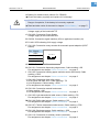
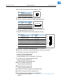
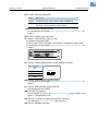
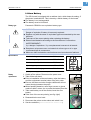
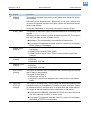
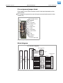
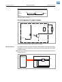
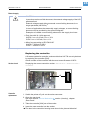
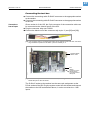
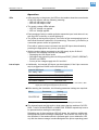
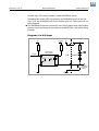
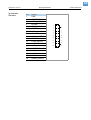
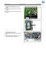
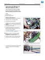
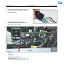
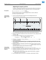
03/10 Rev. 5.04-03
SERVICE MANUAL
64-xx Gen. 3 – DPM Gen. 3 – PEM – PM 3000 – ALX 92x Gen. 3
Service Electronics (Gen. 3)
Handling Boards ........................................... 1
ESD protection .......................................... 1
Handling .................................................... 1
Setting the imprint position ........................ 2
CPU Board .................................................... 3
View .......................................................... 3
Lithium Battery .......................................... 7
Data interfaces at the mounting plate ....... 8
Sensor connections ................................... 9
Centronics daughter board ......................... 10
Application notes ..................................... 10
View ........................................................ 10
Pin assignment ........................................ 11
CF daughter board ...................................... 11
Application notes ..................................... 11
View ........................................................ 11
Connecting .............................................. 12
Operation panel boards .............................. 13
Application notes ..................................... 13
View ........................................................ 13
Output stage board ..................................... 14
Application notes ..................................... 14
View ........................................................ 14
Connections ............................................ 15
USI Board ................................................... 16
Application notes ..................................... 16
View ........................................................ 17
Connectors .............................................. 18
Signals at the D-Sub 15 connector ......... 18
Application of the internal inputs
at CN 300 ................................................ 21
Signal description of the internal inputs at
CN300 ..................................................... 21
Pin assignment jumper block .................. 22
Block diagram ......................................... 22
Circuit diagrams for signal inputs ............ 23
Circuit diagrams for signal outputs .......... 24
Replacing the controller .......................... 25
USI testbox ................................................. 26
Application notes ..................................... 26
View ........................................................ 26
Connecting the test box .......................... 27
Operation .................................................28
Diagram of a USI input ............................29
I/O Board .....................................................30
Application notes .....................................30
View .........................................................30
Connectors ..............................................31
Setting the Interface Parameters .............33
Testing the Serial Interface ......................33
Power Supplies ...........................................34
Application Notes .....................................34
NT400 (A1680) ........................................35
ME500 .....................................................36
HME .........................................................37
Printhead Voltages HME & Standard ......38
Characteristics HME power supply ..........39
OD control sensor (ALX) .............................40
Function ...................................................40
System requirements ..............................40
Assembling the OD-sensor ......................41
Connecting the OD-sensor to AI ..............43
Connecting the OD-sensor to USI ...........44
Connecting the OD-sensor to USI
(with applicator PLC) ...............................47
Settings .......................................................49
Material end / Label sensors ....................49
Light sensor rewinder dancer arm (ALX) .52
Adjusting the imprint position ...................54
Sensor test ..................................................55
General notes ..........................................55
Sensors CPU board (64-xx) .....................56
Sensors CPU board (DPM/PEM/ALX) .....57
Value table for sensor 0.12
(printhead temp.) .....................................57
Sensors output stage boards (64-xx) .......58
Sensors output stage boards (ALX/DPM/
PEM) ........................................................58
1
03/10 Rev. 5.04-03
SERVICE MANUAL
Service Electronics
64-xx Gen. 3 – DPM Gen. 3 – PEM – PM 3000 – ALX 92x Gen. 3
Handling Boards
ESD protection
CAUTION! - The boards can be destroyed by static discharge!
« Before opening the printer, place it on a grounded surface.
« Earth your body using an ESD bracelet or other suitable means, before
touching a board. If no suitable ESD protection is available, touch an
earthed object, e.g. a heating radiator, before touching a board.
« Only place boards on earthed surfaces.
Handling
CAUTION! - The conducting tracks on the boards are very thin. If a board
is bent or warped, the conducting tracks can easily crack.
« Avoid bending or warping boards.
« Avoid the use of excessive force when removing or inserting boards.
2
03/10 Rev. 5.04-03
SERVICE MANUAL
Service Electronics
64-xx Gen. 3 – DPM Gen. 3 – PEM – PM 3000 – ALX 92x Gen. 3
Setting the imprint position
When printing on very long labels, it may happen that the imprint position has
to be set. To do this, proceed as follows:
Preconditions
y
y
y
y
DRUCK PARAMETER > Stanzen Offset = „0 mm“.
DRUCK PARAMETER > Druckausrichtung = „Fuß voraus“.
Erforderliches Etikettenmaterial: Mindestlänge 100 mm, ideal sind 200 mm.
Drucker befindet sich im Produktions-Modus.
3
03/10 Rev. 5.04-03
SERVICE MANUAL
Service Electronics
64-xx Gen. 3 – DPM Gen. 3 – PEM – PM 3000 – ALX 92x Gen. 3
CPU Board
View
A
B
C
D
E F
G
H
AO
I
AN
J
K
L
AM
M
N
O
AL
P
Q
AK
AJ
R
AI
AH
S
T
AG
U
AF
V
AE
AD AC
AA
Z
Y
X
W
AB
[1]
CPU board (A6621).
CAUTION!
If replacing the CPU board, mind the following to avoid malfunctioning:
« Only operate printers with a board index of -05 a with a firmware version of
6.33 or higher!
a) CPU boards with index -05 were built-in starting with serial number 082566 0911.
4
03/10 Rev. 5.04-03
SERVICE MANUAL
Service Electronics
64-xx Gen. 3 – DPM Gen. 3 – PEM – PM 3000 – ALX 92x Gen. 3
A Battery for realtime-clock (Lithium 3V, CR2032)
¯ Check the battery regularly and replace it if necessary!
WARNING!
Danger of explosion, if the battery is incorrectly replaced!
« Read and take notice of the notes in chapter Lithium Battery on page 7!
B CN 1401: Connection Power Supply
Voltage supply of the board with 5 V
C CN 1400: Connection Power Supply
Voltage supply of the board with 24 V
D CN 504: Connection signal interface (USI) or applicator interface (AI)
E D 1401: LED indicating 24 V supply voltage
F CN 1100: Connection rotary encoder for automatic speed adaption (APSF
sensor)
Pin Signal
1
+24 V
2
Impulse B
3
GND
4
Impulse A
1 2 3 4
G CN 501: Connection I/O board
H CN 1101: Connection dispensing edge sensor; Cable marking = OS
Pin assignment see chapter Sensor connections on page 9
I
CN 1102: Connection backing paper rewinder sensor (Ø-control); Cable
marking = DDS
Pin assignment see chapter Sensor connections on page 9
J
y
y
y
CN 1103: Connection feed roller sensor
DPM, PEM, PM 3000, ALX: Cable marking = TS
64-xx Dispenser: Cable marking = DRS
Pin assignment see chapter Sensor connections on page 9
K CN 1104: Connection material end sensor
y Cable marking = MS
y Pin assignment see chapter Sensor connections on page 9
L CN 1105: Light transmission label sensor; Cable marking = PS
Pin assignment see chapter Sensor connections on page 9
M CN 1106: Reflex label sensor; Cable marking = RS
Pin assignment see chapter Sensor connections on page 9
N CN 1107: Fullsize transmission label sensor; Cable marking = FSS
Pin assignment see chapter Sensor connections on page 9
O CN 1108: Singlestart sensor; Cable marking = SSS
Pin assignment see chapter Sensor connections on page 9
P CN 1110: Connection for auxiliary sensor (reserved)
Pin assignment see chapter Sensor connections on page 9
5
03/10 Rev. 5.04-03
SERVICE MANUAL
Service Electronics
64-xx Gen. 3 – DPM Gen. 3 – PEM – PM 3000 – ALX 92x Gen. 3
Q CN 1109: Cover switch; Cable marking = COS
Pin Signal
1
Signal cover switch
2
GND
1
2
R CN 301: Connection data cable power supply
S CN 702: Internal connection RS 485 operating panel
Pin Signal Pin Signal
1
+5 V
4
GND
2
Rx +
5
Tx +
3
Rx –
6
Tx –
123456
T CN 701: Connection external RS 485 operating panel
Pin assignment see CN 702 (S)
U CN 503: Connectioin motor output stages (I2C bus)
Pin Signal
Pin Signal
1
Matmotor_CLK
8
GND
2
Foilmotor_CLK
9
Ext_SCL
3
Matmotor CW/CCW 10
Ext_SDA
4
Foilmotor CW/CCW 11
FPGA_nReset
5
PWM_Ctrl
12
V5_MTIF
6
Perimotor_CLK
13
GND
7
Rewinder_Ctrl
14
GND
1
3
5
7
9
11
13
2
4
6
8
10
12
14
V CN 1002: Connection printhead (KCE)
W CN 1001: Connection printhead (KCE high resolution); reserved
X CN 1000: Connection printhead (KPA)
Y JP 101, JP 102: JTAG jumper
y Only for factory-internal use
y Default setting: JP 101 connected, JP 102 open
Z JP 300, JP 301: Software debug jumper
y Only for factory-internal use
y Default setting: both jumpers open
AA D 301: Software debug LED
Only for factory-internal use
AB D 300: Software debug LED
Only for factory-internal use
AC CN 300: Connection Centronics daughter board
AD CN 500: Connection RFID read/write unit
AE CN 1200: Connection Ethernet 10/100 Base T
Pin assignment see chapter Data interfaces at the mounting plate on
page 8
6
03/10 Rev. 5.04-03
SERVICE MANUAL
Service Electronics
64-xx Gen. 3 – DPM Gen. 3 – PEM – PM 3000 – ALX 92x Gen. 3
AF D 1200: Ethernet status LED:
LED
Meaning
Green
Continuously lit: High transfer rate (100 Mbit/s)
Yellow
Continuously lit: Device is connected with the network
Flashing: Communication with network
AGCN 703: Serial interface RS 232
Pin assignment see chapter Data interfaces at the mounting plate on
page 8
AH LS 300: Audible signal generator
AI
y
y
y
CN 401: USB interface (type A, host)
Keyboard connection [2A]
Inter Connect Port (ICP) [2B]; Connection to a dispenser main board
Pin assignment see chapter Data interfaces at the mounting plate on
page 8
B
A
[2]
Position of the two USB host interfaces.
AJ CN 402: Internal USB interface (host), parallel to CN 401
Pin Signal
1
+5 V
2
D–
3
D+
4
GND
1 2 3 4
AK CN 400: USB interface (type B, device)
Pin assignment see chapter Data interfaces at the mounting plate on
page 8
AL CN 403: USB interface (host); reserved
Pin assignment see CN 402
AM CN 1300: CF-card slot
List of suitable CF-cards: see Plug-in card manual , topic section „Card
types“, „CompactFlash card“
AN CN 1301: Interface for optional second CF-card slot
See Abschnitt CF daughter board auf Seite 11.
AO CN 101: SD/MMC-card slot
7
03/10 Rev. 5.04-03
SERVICE MANUAL
Service Electronics
64-xx Gen. 3 – DPM Gen. 3 – PEM – PM 3000 – ALX 92x Gen. 3
Lithium Battery
The CPU board is equipped with a realtime clock, which keeps its setting, if
the printer is switched off. This is done by a lithium battery on the board.
¯ The battery is not rechargeable!
¯ The battery must be UL-listed!
Battery type
Panasonic CR2032 or an equivalent battery type.
WARNING!
Danger of explosion if battery is incorrectly replaced.
« Replace only with the same or equivalent type recommended by the manufacturer.
« Take care of the correct polarity when replacing the battery.
« Discard used batteries according to the manufacturer´s instructions.
AVERTISSEMENT!
Il y a danger d´explosion s´il y a remplacement incorrect de la batterie.
« Remplacer uniquement avec une batterie du même type ou d´un type
recommendé par le constructeur.
« Mettre au rébut les batteries conformément aux instructions du fabricant.
Specifications
Nominal voltage
3V
Nominal capacity
220 mAh
Continous standard load
0.2 A
Operating temperature
-30 to +60 °C
Max. abnormal charging current
5.0 mA
[Tab. 1]
Battery
replacement
Battery type CR2032 - specifications and dimensions.
1. Switch off the printer. Disconnect the power cord.
2. Take off the rear hood.
¯ Prior to installation of the new battery: wipe the battery
and the equipement terminal clean using a dry cloth.
¯ Ensure, that dust and other foreign substances will not
cause shorting between the poles.
¯ When handling batteries, wear finger covers or gloves
made of rubber, cotton, etc. to protect the battery from dirt.
3. Take used battery out of the socket; insert the new
battery.
¯ Take care of the correct polarity (see fig. right)!
4. Reassemble the rear hood.
5. Reconnect the printer to the mains and switch it on.
6. Set time and date (SYSTEM PARAMETER > Realtime clock).
8
03/10 Rev. 5.04-03
SERVICE MANUAL
Service Electronics
64-xx Gen. 3 – DPM Gen. 3 – PEM – PM 3000 – ALX 92x Gen. 3
Data interfaces at the mounting plate
(A) Ethernet
Pin Signal
1
TD +
2
TD –
3
RD +
4
Termination
5
Termination
6
RD –
7
Termination
8
Termination
[Tab. 2]
(B) RS 232
A
B
Pin assignment of the Ethernet interface (RJ 45).
¯ Pin assignment looked at from „PC point of view“!
C
(Device = DCE)
Signal
1,4,6
connected
9
2
RxD
8
3
TxD
5
GND
7
RTS
8
CTS
9
not used
[Tab. 3]
(C) USB-A
Signal
1
+5 V
2
Data –
3
Data +
4
GND
4
3
7
2
6
1
1
2
3
4
Pin assignment of the USB-A interface (host, type A).
Pin
Signal
1
+5 V
2
Data –
3
Data +
4
GND
[Tab. 5]
5
Pin assignment of the RS 232 interface (D-Sub 9, female).
Pin
[Tab. 4]
(D) USB-B
D
Pin
Pin assignment of the USB-B interface (device, type B).
9
03/10 Rev. 5.04-03
SERVICE MANUAL
Service Electronics
64-xx Gen. 3 – DPM Gen. 3 – PEM – PM 3000 – ALX 92x Gen. 3
Sensor connections
The pin assignment and connection diagram described below applies to the
sensor connections H to P in fig. [1] (yellow marking in [3]).
Pin Signal
1
Anode
2
Cathode
3
Collector
4
Emitter
[Tab. 6]
[3]
1
2
3
4
Pin assignment and connection diagram of the sensor connectors.
Right: yellow marking = sensor connections
on the CPU board.
10
03/10 Rev. 5.04-03
SERVICE MANUAL
Service Electronics
64-xx Gen. 3 – DPM Gen. 3 – PEM – PM 3000 – ALX 92x Gen. 3
Centronics daughter board
Application notes
This board offers the possibility to optionally equip the device with a parallel
Centronics interface.
Requirements:
¯ For reasons of limited mounting places, this board can not be mounted into
a device, which is already equipped with the optional I/O-board.
¯ This board can not be mounted into a PM 3000.
y CPU-board A6621
y Device firmware version 4.12 or higher
View
B
C
A
D
[4]
A
B
C
D
E
Centronics daughter board (A6758).
Centronics jack IEEE 1284 B 36pin
JP 100: Jumper connected = 5 V at pin 35
JP 101: Jumper connected = 5 V at pin 18
FFC (Flat Flex Cable) connection to CPU-board A6621 (connect there to
CN 1301 [5])
[5]
Mounting position of the board. The silver coloured contacts (E) at the FFC-cable must
show to the right when connecting it (see arrow).
11
03/10 Rev. 5.04-03
SERVICE MANUAL
Service Electronics
64-xx Gen. 3 – DPM Gen. 3 – PEM – PM 3000 – ALX 92x Gen. 3
Pin assignment
36 - SELECT_IN\
35 - VCC 5V (JP100 geschl.)
34 - n.b.
33 - GND
32 - FAULT\
31 - INIT\
30 - GND
29 - GND
28 - GND
27 - GND
26 - GND
25 - GND
24 - GND
23 - GND
22 - GND
21 - GND
20 - GND
19 - GND
[6]
18 - VCC 5V (JP101 geschl.)
17 - n.b.
16 - n.b.
15 - n.b.
14 - AUTO_FEED\
13 - SELECT
12 - PAPER END
11 - BUSY\
10 - ACK\
9 - LPT_D7
8 - LPT_D6
7 - LPT_D5
6 - LPT_D4
5 - LPT_D3
4 - LPT_D2
3 - LPT_D1
2 - LPT_D0
1 - STROBE\
Pin assignment of the Centronics jack IEEE 1284 B.
CF daughter board
Application notes
CF = CompactFlash
This board is for optional equipement of the device with a second slot for CFcards (the first slot is standard on the CPU-board).
¯ This board can not be mounted into a PM 3000.
Requirements:
y CPU-board A6621
y Device firmware version 5.00 or above
y List of suitable CF-cards: see Plug-in card manual , topic section „Card
types“, „CompactFlash-card“.
View
A
B
[7]
CF daughter board (A6624).
A CF-card slot
B Plug-in contacts for CPU-board connection (connect there to CN 1301)
12
03/10 Rev. 5.04-03
SERVICE MANUAL
Service Electronics
64-xx Gen. 3 – DPM Gen. 3 – PEM – PM 3000 – ALX 92x Gen. 3
Connecting
Tool: Cross-head screwdriver
1. Remove screws [8A]. Remove cover plate
[8B].
C
A
B
[8]
CPU board with mounted cover plate (B).
2. Lay the left board edge onto the remaining
metal angle [9D]. Press the right side of
the board with its contacts [7B] into the
connector [8C] on the CPU-board.
D
[9]
3. Fix the board to the metal angle using the
two screws [10E]. Additionally fix the
board with two screws from the CPUboard rear side into the hex bolts at
position [10F].
Plugging in the adapter board.
E
[10] Fixing the adapter board.
F
13
03/10 Rev. 5.04-03
SERVICE MANUAL
Service Electronics
64-xx Gen. 3 – DPM Gen. 3 – PEM – PM 3000 – ALX 92x Gen. 3
Operation panel boards
Application notes
Requirements:
y CPU-board A6621
y Device firmware version 4.12 or above
View
D
A
B
C
A
C
B
[11] Operation panel boards for 64-xx (left: A7149) and for DPM/PEM/ALX (right: A6626).
A Connection programming adapter (only for factory-internal use)
B Connection CPU-board (connect there to CN 701)
¯ Caution - compared to electronics „…6/06“, the article numbers for the cables
were changed. The valid numbers are:
– 64-xx: A7058
– DPM, PEM, PM 3000: A8176
– ALX 92x: A8177
C Connection I2C-bus (reserved)
D Connection for fifth button (reserved, only at board A6626)
14
03/10 Rev. 5.04-03
SERVICE MANUAL
Service Electronics
64-xx Gen. 3 – DPM Gen. 3 – PEM – PM 3000 – ALX 92x Gen. 3
Output stage board
Application notes
¯ In case of replacing an output stage board, keep in mind the following points
(see tab. [12]):
– Article number (see label on the board)
– PIC version (see label on the microcontroller [12G])
– Jumper setting (matching the motor)
View
A
G
xxxxxxxxxxxx
B
J6
J1
J7
C
D
F
E
[12] Output stage board (A2742).
A J4: Sensor
B J8: Optional sensor
C Jumper setting of the motor
type to which the board applies
D J3: Motor
Output stage applies to…
PIC version
E J2: Connection CPU-board
(Data cable)
F J12: Connection power supply
G PIC version
Part no. Motor
cable
Sensor
cable
Jumper set
J6
J1
J7
Feed motor (ALX)
M04A V3 F73
A6713
FM
–
X
X
X
Feed motor
M04A V3 F73
A2742
FM
–
X
X
X
Ribbon motor
M04A V3 F73
A2742
RM
RS
X
X
Printhead motor
M04A V3 F73
A2742
HM
HS
X
Rewinder/Feed motor (64-xx Disp.)
M04A V3 F73
A2742
DRM
–
M04A V3 F73
A2742
OM
OS
Options motor (PM 3000)
M04A V3 F73
A2742
Deflection motor (64-xx Dispenser)
M04A V3 F73
A2742
DLM
DLS
R04A V4 F876A
A3036
WM
WS
Options
motor a
(64-xx)
Rewinder motor (ALX)
[Tab. 1]
Overwiew: output stage configurations for the different motors.
a) for „Cutter 2000“ or „Rewinder 2000“.
MOTOR SENSOR
X
X
X
X
X
X
X
X
15
03/10 Rev. 5.04-03
SERVICE MANUAL
Service Electronics
64-xx Gen. 3 – DPM Gen. 3 – PEM – PM 3000 – ALX 92x Gen. 3
Connections
Picture
Comp. Type on board
diagr.
J4
PANCON
MLAS 100-04
Type at cable
Pin assignment on
board
AMP 643813-4 or
AUK MK-04H
1-A
2 - K (GND)
3-C
4 - E (GND)
J3
PANCON
MLAS 100-04
AMP 643813-4 or
AUK MK-04H
1-A
2 - A\
M
J2
Wieson
2120-14RS5
3-B
4 - B\
11 - Reset\
9 - I2C-SCL
1 - Clock 0
MOLEX 70450
Version b
10 - I2C-SDA
14 - GND
J12
[Tab. 2]
AMP 640389-6
Connections on the output stage board.
AMP 0-644465-6
MTA 156 18 AWG
1 - 5V
2 - GND
3 - n.c.
4 - GND
5 - 38..54V
6 - GND
16
03/10 Rev. 5.04-03
SERVICE MANUAL
Service Electronics
64-xx Gen. 3 – DPM Gen. 3 – PEM – PM 3000 – ALX 92x Gen. 3
USI Board
Application notes
Utilization
The USI (Universal Signal Interface) is an optional interface for all machine
types listed in the headline of this page.
USI-equipped machines can for example control applicators or scanners.
The input signals can be used to trigger the print-dispense-process. The output lines signal the operating status - e.g. material or ribbon end - so that the
machine can be integrated completely into a system.
The USI comes on a separate board and can be easily retrofitted.
Compatibility
¯ DPM, ALX 92x: USI and AI (Applicator Interface) can not be built into the
same device.
A
C
B
[13] Version designations on the USI board.
Version
¯ The functionality described in this section is only then fully available, if USI
board, Controller and printer firmware match the following requirements:
y USI board: At least A2062-08 (5 V USI) or A2345-09 (24 V USI) or with a
higher index number. Displaying the index number: Sticker on the board
[13B, C].
y USI controller: At least V6-T36 or a later version with a higher V-number.
Displaying the version:
– Sticker on the microcontroller [13A]
– Parameter menu: SERVICE DATA > > MODULE FW VERS. > USI interface
¯ Controller version older than V6-T36: Update is only possible by
exchanging the controller (see chapter Replacing the controller on
page 25).
¯ Controller version V6-T36 or higher: Update can be done by loading new
firmware (same procedure as for printer firmware update, see topic
section Firmware ). Requirement: printer firmware of at least version
5.30 is installed.
17
03/10 Rev. 5.04-03
SERVICE MANUAL
Service Electronics
64-xx Gen. 3 – DPM Gen. 3 – PEM – PM 3000 – ALX 92x Gen. 3
y Printer firmware: 5.0 or higher. Displaying the firmware version:
– Parameter menu: SERVICE DATA > > MODULE FW VERS. > System version
– During powering up the printer
Connection type
NPN
Signal voltage
optionally 5 or 24 V
View
SPS (optional)
USI board index number
(here: 04)
Micro controller version
number (here: V2)
USI signals
(VB200)
CPU board
(CN101)
JP8
Function
5V internal voltage supply active on
Pin2/DB-15
5V external voltage supply on Pin 2/
DB-15
[14] USI-board (A2345).
Power supply
(CN100)
Connector for internal USI inputs
(CN 300)
18
03/10 Rev. 5.04-03
SERVICE MANUAL
Service Electronics
64-xx Gen. 3 – DPM Gen. 3 – PEM – PM 3000 – ALX 92x Gen. 3
Connectors
Picture
Comp. Type on
Diagr. board
Pin assignment on board
CN100 AMP
640457-4
1 - EXT 24V
2 - n.c.
3 - n.c.
4 - EXT GND
CN101 Cable is
soldered
to the
board
2 - EX_RES\
4 - AI_IRQ\
6 - H8_IRQ4\
8 - SCL
10 - SDA
12 - n.c.
14 - APSF
CN300
VB200
[Tab. 3]
1 - VCC +5V
3 - VCC +5V
5 - VCC +5V
7 - GND
9 - GND
11 - n. c.
13 - GND
1 - OD control material
2 - Applicator homeposition error
3 - Applicator touchdown error
4 - SPS ready/error
5 - GND
15 - MACHINE STATUS\
14 - DATA_RDY\
13 - RIBBON_OUT\
12 - MEDIA_OUT\
11 - PRINT_END\
10 - ERROR\
9 - WARNING
8 - GND_EXT
7 - 24V_EXT
6 - REPRINT\
5 - PAUSE\
4 - FEED\
3 - START_PRINT\
2 - 5V_EXT
1 - GND_EXT
Connectors on the USI board.
Signals at the D-Sub 15 connector
Pin Signal
Function
1
GND_EXT
Ground contact
2
JP8 connected: Internal 5 V source can be used via the wire for external
5V_EXT
(Voltage supply) sensors.
JP8 clear: Wire can be used for an external 5 V source.
3
START_PRINT\ The machine starts printing depending on the setting of parameter DP INTER(Input)
FACE > Start print mode.
Preconditions: Printjob is available (DATA RDY\ low), printer is in online
mode, no error messages.
4
FEED\
(Input)
[Tab. 4]
Feeding of the label material as long as the signal is low. Minimum feed
quantity: 1 label. The display shows „USI feed“ during feeding.
Preconditions for feeding:
y Offline mode, printing has been stopped or the printer is in USI-paused
mode.
y Online mode and no print job loaded.
Signal designations and functions of the USI interface.
19
03/10 Rev. 5.04-03
SERVICE MANUAL
Service Electronics
64-xx Gen. 3 – DPM Gen. 3 – PEM – PM 3000 – ALX 92x Gen. 3
Pin Signal
Function
5
A high-low-transition switches the printer into the USI-paused mode.
A further high-low-transition switches the printer back into the online mode.
PAUSE\
(Input)
If parameter DP INTERFACE > Start print mode is set to Level high active or Level
low active, any activating of the PAUSE\ signal stops the printing after the
current label.
Features:
y „USI Pause“ is displayed
y ERROR\ is activ (low)
y If a print job is available: DATA RDY\ is inactive (high)
y Start print signals are suppressed
y Reprint requests are proceeded after switching into online mode.
y Precondition: START PRINT\ inactive (high).
6
REPRINT\
(Input)
The last printed label is being reprinted as long as REPRINT\ is low.
Minimum reprint quantity: 1 label.
Preconditions:
y The label which is ought to be reprinted, must be ready printed and
dispensed.
y Printer is in online mode.
y If a REPRINT\ is triggered while the printer is in USI-pause mode, the
reprint will be proceeded as soon as the printer is switched back in
online mode.
y Precondition: START PRINT\ inactive (high).
7
Voltage supply for external sensors
24V_EXT
(Voltage supply)
8
GND_EXT
(GND)
Ground contact
9
WARNING
(Output)
Ribbon low warning:
The signal is activated (high), if
a) DP INTERFACE > Ribbon signal = activated and
b) The ribbon stock is below the threshold value, which is set in parameter
SYSTEM PARAMETER > Ribbon warning. After changing the ribbon roll, the signal
will be inactivated after a short time.
Material end warning:
The signal is activated (high), if
a) DP INTERFACE > Material signal = activated and
b) The label material stock is below the threshold, which is set by positioning the light barrier. After changing the material roll, the signal will be
inactivated.
The WARNING output is only then inactivated (low), if ribbon and material
both are available in a sufficient amount. If one of both rolls falls below the
threshold value, the output switches activ (high).
In practice, the more or less eccentric running material roll will trigger the
material warning repeatedly, until the roll diameter falls below a certain tolerance zone.
This signal is only a warning, what means that the printing goes on.
[Tab. 4]
(Cont.)Signal designations and functions of the USI interface.
20
03/10 Rev. 5.04-03
SERVICE MANUAL
Service Electronics
64-xx Gen. 3 – DPM Gen. 3 – PEM – PM 3000 – ALX 92x Gen. 3
Pin Signal
Function
10
This output is activated (low) during every status which keeps the printer
from printing:
ERROR\
(Output)
USI-pause mode, stopped mode, offline mode, cover open, material end,
no punch recognized, pressure roller open, ribbon end and other failures
which avoid printing.
During the initialization of the printer, the output is inactive (high)!
11
PRINT_END\
The manner in which this output is switched depends on the setting of parameter DP INTERFACE > End print mode.
Difference to older versions of printer firmware (below 2.46): The output is
now also activated as long as labels are fed.
¯ Limitation: This functionality is not available in Batch mode!
¯ 64-xx with LTSI applicator mounted (with PLC version 5.0 and higher):
PRINT_END\ is not available.
11
HOME_POS\
(Output)
¯ Only valid for 64-xx with LTSI applicator mounted (with PLC version 5.0
and higher):
y HOME_POS\ replaces PRINT_END\.
y HOME_POS\ is active, if the LTSI is in home position (upper limit
position)
12
MEDIA_OUT\
(Output)
Low in case of material end. Additionally activated are:
y ERROR\
y MACHINE STATUS\
13
RIBBON_OUT\
(Output)
Low in case of ribbon end. Additionally activated are:
y ERROR\
y MACHINE STATUS\
14
DATA_RDY\
(Output)
This signal is activated (low), if the printer has finished image processing
and is ready to start printing.
The signal is inactivated, if
y the print job is done, or
y the printer is switched to stopped mode, offline mode or USI-pause
mode.
15
MACHINE
STATUS\
(Output)
This output is activated (low), if the printing has been interrupted by a disturbance or an error. Examples are: Pressure roll open, hood open, ribbonor material end error, start print error or another fault that avoids printing.
The output is also activated during the initialization of the printer.
¯ In comparison to ERROR\, MACHINE STATUS\ is not low if the printer
has been switched to offline or pause mode.
¯ 64-xx with LTSI applicator mounted (with PLC version 5.0 and higher):
MACHINE_STATUS\ is not available.
[Tab. 4]
(Cont.)Signal designations and functions of the USI interface.
21
03/10 Rev. 5.04-03
SERVICE MANUAL
Service Electronics
64-xx Gen. 3 – DPM Gen. 3 – PEM – PM 3000 – ALX 92x Gen. 3
Application of the internal inputs at CN 300
The following parameter settings are required to make the internal inputs
useable:
PLC
For usage with PLC:
y DP INTERFACE > Interface type = USI Applicator
y DP INTERFACE > Internal inputs = Enabled
OD sensor
For useage with „OD sensor material“:
y DP INTERFACE > Material signal = Enabled
y DP INTERFACE > Internal inputs = Enabled
If PLC and „OD sensor material“ are ought to be used, all three parameter
settings have to be done.
¯ To all four inputs applies: The input is inactivated if it is connected to ground
potential!
Signal description of the internal inputs at CN300
Pin Signal
Signal
type
Function
1
OD control
material
In
To be applied to the OD control material option.
The signal WARNING at pin 9 of the DB 15 is switched activ, if
• Parameter DP INTERFACE > Material Signal = Activated and
• the input is high
2
Applicator
fault home
position
In
3
Applicator
fault touch
down
In
4
PLC ready /
fault
In
5
GND
Ground
[Tab. 5]
If one of the inputs is high or makes a low-high-transition, the appropriate status message is displayed at the printer. Additionally,
the outputs ERROR\ and MACHINE STATUS\ will be activated
(low).
GND potential of the internal inputs
Signal designations and functions of the internal inputs
22
03/10 Rev. 5.04-03
SERVICE MANUAL
Service Electronics
64-xx Gen. 3 – DPM Gen. 3 – PEM – PM 3000 – ALX 92x Gen. 3
Pin assignment jumper block
Each signal of the D-Sub connector can be interrupted separately at the
jumper block.
¯ The voltage and ground wires are through-connected and cannot be interrupted [15]!
GND
MACHINE STATUS\
REPRINT\
24 V
DATA RDY\
RIBBON OUT\
PAUSE\
MEDIA OUT\
FEED\
PRINT END\
START PRINT\
5V
GND
WARNING
ERROR\
APPLICATOR MODE
[15] Pin assignment jumper block
Block diagram
USI Block Diagram
SPS Connectors
CN300
MUX
7
6
5
4
GND
SPS Ready\ /Error
Touch Down Error
Home Pos. Error
Material Low
Pin 5
Pin 4 internal Inputs
Pin 3
only
Pin 2
Pin 1
USI Connector
[16] Block diagram of the USI
USI logic
USI Controller
Engine Controller
Sub-D 15
3
2
1
0
Start Print\
Feed\
Pause\
Reprint\
Ribbon Low
Error\
Print End\
Media Out\
Ribbon Out\
Data Ready\
Machine Status\
Applicator Mode
GND
5V
GND
24V
JP303
JP302
JP301
JP300
JP204
JP203
JP205
JP206
JP200
JP201
JP202
CN200
CN201
CN202
CN204
CN203
Start Print\
Feed\
Pause\
Reprint\
Ribbon Low
Error\
Print End\
Media Out\
Ribbon Out\
Data Ready\
Machine Status\
GND
5V
GND
24V
Pin 3
Pin 4
Pin 5
Pin 6
Pin 9
Pin 10
Pin 11
Pin 12
Pin 13
Pin 14
Pin 15
Pin 1
Pin 2
Pin 8
Pin 7
23
03/10 Rev. 5.04-03
SERVICE MANUAL
Service Electronics
64-xx Gen. 3 – DPM Gen. 3 – PEM – PM 3000 – ALX 92x Gen. 3
Circuit diagrams for signal inputs
[17] Main circuit for signal inputs (NPN) at the USI interface (here: connecting a start sensor).
Timing waveform of
input signals
The following criteria must be matched by the input signals of the USI:
¯ Only one signal at a time may be switched active!
¯ The input signals must switch bounce-free!
min. 10ms
min. 10ms
min. 10ms
min. 10ms
min. 10ms
min. 10ms
min. 10ms
min. 10ms
min. 10ms
min. 10ms
Start Print
(Puls mode falling edge)
min. 10ms
Feed
min. 10ms
Reprint
min. 10ms
min. 10ms
Pause
print 1 label
min. 10ms
print 1 label
imprinting of the
previous label must
be finished!
min. 10ms
Pause-mode on
start feeding
labels
print 1 label
Pause-mode off
stop feeding
labels
min. 10ms
min. 10ms
min. 10ms
min. 10ms
min. 10ms
reprint last label
(if not disabled)
imprinting of the previous
label must be finished!
min. 10ms
min. 10ms
Start Print
(Puls mode both edges)
min. 10ms
Feed
min. 10ms
min. 10ms
Reprint
min. 10ms
min. 10ms
Pause
print 1 label
imprinting of the
previous label must
print 1 label
be finished!
imprinting of the
Pause-mode on
previous label must
be finished!
print 1 label
start feeding
labels
stop feeding
labels
Store to reprint last label
(if reprint functionality is
enabled)
No reprint because of
Pause-mode!
Pause-mode off
reprint last label!
[18] Examples of timing waveform for the USI inputs.
print 1 label
imprinting of the
previous label must
be finished!
reprint last label
(if not disabled)
imprinting of the
previous label must
be finished!
24
03/10 Rev. 5.04-03
SERVICE MANUAL
Service Electronics
64-xx Gen. 3 – DPM Gen. 3 – PEM – PM 3000 – ALX 92x Gen. 3
Start Print
Feed
Reprint
min. 10ms
min. 10ms
Pause
[19] Signal timing - to be met.
Circuit diagrams for signal outputs
5V
24 V
Load
USI board
47k
Output
Controller
[20] Main circuit (NPN) for signal outputs at the USI interface.
In the state of delivery (jumper 8 closed, cable A2059 connected), the supply
voltages (5 V on pin 2 and 24 V on pin 8) are provided by the USI. The output
current is limited:
¯ Maximum current per output line: 50 mA; all output currents together may not
exceed 700 mA.
USI board / USI-Platine
Netzteil /
Power Supply
JP8
24 V
0V
5V
5 V Pin 2
0 V Pin 1 / 8
Kabel / Cable
A2059
24 V Pin 7
0 V Pin 1 / 8
[21] USI in the state of delivery: The voltage cable is connected, JP 8 is closed.
Z0119.cdr
Max output current
25
03/10 Rev. 5.04-03
SERVICE MANUAL
Service Electronics
64-xx Gen. 3 – DPM Gen. 3 – PEM – PM 3000 – ALX 92x Gen. 3
External supply
CAUTION
In previous versions of this document, the external voltage supply of the USI
was described.
External voltage supply without external current limiting elements is no
longer permitted (risk of fire) a.
In case of applications that externally supply voltages, a current limiting
element must be provided by the system integrator.
Examples of suitable current limiting elements in the supply circuit are:
y Poly fuse with UL 1434 approval
24 VDC: Ihold = 0.65 mA; Umin = 30 V
5 VDC: Ihold = 0.65 mA; Umin = 6 V
y Micro fuse according to IEC EN 60127
24 VDC: T 630 mA L 250 V
5 VDC: T 630 mA L 250 V
a) Due to an update of EN 60950-1.
Replacing the controller
A firmware update for controller versions older than V6-T36 can only be done
by replacing the controller [22A].
Article number of the controller with the most recent firmware: A3379.
Version check
Displaying the current controller version: SERVICE DATA > >MODULE FW VERS. >
USI interface.
A
Z0151.cdr
[22] The controller (A) contains the USI firmware.
Controller
replacement
1. Switch the printer off, pull out the mains connector.
2. Open the rear hood.
See topic section Service Mechanics , section „Housing“, chapter
„Rear hood“.
3. Take the controller [22A] out of the socket.
4. Insert the new controller into the socket.
¯ The dent in the controller housing must show in the pictured direction!
26
03/10 Rev. 5.04-03
SERVICE MANUAL
Service Electronics
64-xx Gen. 3 – DPM Gen. 3 – PEM – PM 3000 – ALX 92x Gen. 3
USI testbox
Application notes
Simulating USI inputs
Checking USI outputs
Monitoring of drive signals sent by the system control
Aid for setting up the machine.
[23] Left side: USI testbox (A2739); right side: connecting cable (A2842). Both parts are required for application (Both parts: A2843).
View
Connection to the USI
Survey of the voltage supply at the
D-Sub connector of the USI
(The test box needs 5 V supply voltage!)
Survey of in- and outputs at the
D-Sub connector of the USI
Simulation of the 4 inputs at the
D-Sub connector of the USI
(4 pushbuttons)
Simulation of the 4 internal inputs at the
CN300 connector of the USI (from vers. 4 on)
(4 switches)
z0175E.CDR
y
y
y
y
Optional connection of a customer control unit
or product sensor (monitoring)
[24] Operating parts and connections of the USI testbox.
27
03/10 Rev. 5.04-03
SERVICE MANUAL
Service Electronics
64-xx Gen. 3 – DPM Gen. 3 – PEM – PM 3000 – ALX 92x Gen. 3
Connecting the test box
« Connect the connecting cable D-Sub25 connector to the appropriate socket
at the testbox.
« Connect the connecting cable D-Sub15 connector to the appropriate socket
at the USI.
Given version 4 of the USI, the 5-pin connector of the connection cable can
be connected to the internal inputs of the USI:
« Plug the connector strip onto CN300.
¯ Connect the black cord of the connector strip to pin 1! (see [25] and [26])
[25] The connector strip for connecting the testbox to the internal inputs of the USI. The mounting orientation is printed on the cable: „black on CN300 pin 1“.
Flachbandkabel /
Ribbon cable
Pin 1
z0167.cdr
Connection to
internal inputs
CN300:
Anschluss interne
USI-Eingänge /
Connector internal
USI-Inputs
[26] Pin 1 is the first pin in direction of the ribbon cable; the writing CN300 Pin 1 can be found
beside the pins on the USI board.
The D-Sub15 socket at the testbox has the same pin assignment as the
D-Sub socket of the USI. Plug the system control into this socket and connect
the testbox to the USI as described above, in order to monitor the 4 USI
inputs.
28
03/10 Rev. 5.04-03
SERVICE MANUAL
Service Electronics
64-xx Gen. 3 – DPM Gen. 3 – PEM – PM 3000 – ALX 92x Gen. 3
Operation
LEDs
y After powering on the printer, the LEDs on the testbox show the current levels
of the USI outputs, with the following meaning:
– LED off: USI output = High
– LED on: USI output = Low
y The supply voltage LEDs indicate:
– LED off: Voltage not applied
– LED on: Voltage applied
y Each pressing of a key or switch pulls the respective input level down to Low,
with the LED on the key or switch lighting up.
y The LEDs on the keys also light up, if the level of the corresponging input at
the D-Sub15 socket is pulled to Low (monitoring). This can e.g. be done by a
connected system control or light barrier.
Even with a system control connected can the USI inputs be activated by
pressing the appropriate key (set-up operation).
y With the testbox being connected to the USI merely by the D-Sub15
connector, the following functions are available:
– Displaying the USI output levels
– Simulation and monitoring of the 4 USI inputs START_PRINT\, REPRINT\,
PAUSE\ und FEED\
– Survey of the voltage supply with 5 V and 24 V
Internal inputs
y Additionally, the internal USI-inputs can be simulated, if the 5-pin connector
strip is plugged into CN300 on the USI board [26].
Internal USI-input
Switch
PLC ready / fault
PLC ERROR
Applicator fault touch down
TOUCH DOWN ERROR
Applicator fault home position
HOME POS. ERROR
OD control material
MATERIAL LOW
[Tab. 6]
The switch designations (right column), which are printed on the testbox, differ
slightly from the signal designations (left column).
¯ Befor starting the simulation, the following parameter settings are required:
Menu
DP INTERFACE
[Tab. 7]
Parameter
Setting
Interface type
USI applicator
Material signal
Enabled
Internal inputs
Enabled
Parameter settings which should be done before starting the simulation.
¯ The internal inputs are high-active, what means that the switches PLC ERROR, TOUCH DOWN ERROR or HOME POS. ERROR respectively have to
be pressed before starting the simulation!
Releasing one of those switches (LED off) stops the machine; additionally,
the appropriate status message is displayed. The machine can only be further operated, if the testbox switch is pressed again (error withdrawn, LED
on) and the status message is acknowledged at the printer operating panel.
29
03/10 Rev. 5.04-03
SERVICE MANUAL
Service Electronics
64-xx Gen. 3 – DPM Gen. 3 – PEM – PM 3000 – ALX 92x Gen. 3
Internal input „OD control material“ (switch MATERIAL LOW):
Releasing this switch (LED off) switches the WARNING-output of the USI
high. Thus, the WARNING-LED on the testbox goes out. The machine is not
being stopped.
¯ The WARNING-output also shows the close end of ribbon stock; what means
that this ouput can change its level without the MATERIAL LOW switch being
pressed.
Diagram of a USI input
5V
5V/24V
5V
Optokoppler /
Opto-coupler
Controller
USI
Testbox
z0165.cdr
Kundensteuerung /
Customer
control
GND
[27] Simplyfied diagram of a USI input.
Ext.-GND
30
03/10 Rev. 5.04-03
SERVICE MANUAL
Service Electronics
64-xx Gen. 3 – DPM Gen. 3 – PEM – PM 3000 – ALX 92x Gen. 3
I/O Board
Application notes
¯ The I/O board can not be mounted into a PM 3000.
Requirements
Device firmware version 5.00 or above.
Applications
The I/O board may be used for 2 different applications:
y 2nd RS 232 interface:
The I/O board provides a RS 232 interface, which can be applied additionally
to the one on the CPU board. The 2nd interface can e.g. be used to connect
a bar code scanner.
y RS 422/485 interface:
If there is a long distance between host and printer, RS 485 or RS 422 is
sometimes used instead of RS 232 or Centronics. This is often realized in industrial plants, where galvanic isolation is required to avoid ground loops.
¯ The two serial interface types cannot be used at the same time.
View
A
B
C
[28] I/O-board (A8258).
A CN 201: Not yet supported
B CN 101: RS 232/422/485
C CN 101: Connection CPU-board (connect there to CN 501)
31
03/10 Rev. 5.04-03
SERVICE MANUAL
Service Electronics
64-xx Gen. 3 – DPM Gen. 3 – PEM – PM 3000 – ALX 92x Gen. 3
Connectors
(B) RS 232
¯ Pin assignment looked at from „PC point of view“ (Device = DCE)!
Pin
Signal name
(host)
Signal direction at the
I/O board
9
1
DCD
Short with DTR & DSR
8
2
RxD
Out
7
3
TxD
In
6
4
DTR
Short with DCD & DSR
5
GND
6
DSR
Short with DCD & DTR
7
RTS
In
8
CTS
Out
9
RI
Not connected
[Tab. 8]
(B) RS 422/485
5
4
3
2
1
Pin assignment of the RS 232 interface (D-Sub 9, female).
« Set INTERF. PARAM. > COM2 PORT > Serial Port Mode to „RS 422“ or „RS 485“.
¯ Pin assignment looked at from „PC point of view“ (Device = DCE)!
Pin
Signal name
(host)
1
Signal direction at the
I/O board
9
Not connected
8
2
Rx-
Out
7
3
Tx-
In
6
Termination
5
GND
6
Termination a)
7
Tx+
In
8
Rx+
Out
[Tab. 9]
4
3
2
1
a
4
9
5
Not connected
Pin assignment at the RS 422/485 interface (D-Sub, female).
a) 110 Ohm
RS 422/485
termination
At the last printer at the RS 422/485 line, connect the following pins (inside of
the cable connector):
y Pins 3 and 4 (Tx-)
y Pins 6 and 7 (Tx+)
RS 485 2-wire
connection
At each printer on the bus line, connect the following pins (inside of the cable
connector):
y Pins 2 and 3 (Tx-/Rx-)
y Pins 7 and 8 (Tx+/Rx-)
32
03/10 Rev. 5.04-03
SERVICE MANUAL
Service Electronics
64-xx Gen. 3 – DPM Gen. 3 – PEM – PM 3000 – ALX 92x Gen. 3
(C) Connection
CPU board
Pin
Signal
1
GND
2
nREPRINT
3
FPGA_U4RX
4
nSTART
5
FPGA_U4TX
6
nFEED
7
GND
8
nPAUSE
9
FPGA_U4CTS
10
ERROR
11
FPGA_U4RTS
12
WARNING
13
GND
14
PRINTEND
15
+ 3,3V
16
+ 5V
17
DXEN
18
RS485_nRS323
2
1
4
3
6
5
8
7
10
9
12
11
14
13
16
15
18
17
[Tab. 10] Pin assignment at the CN 101 connector.
33
03/10 Rev. 5.04-03
SERVICE MANUAL
Service Electronics
64-xx Gen. 3 – DPM Gen. 3 – PEM – PM 3000 – ALX 92x Gen. 3
Setting the Interface Parameters
With an I/O board mounted, the following additional menus appear in the
printer menu:
y INTERF. PARAM. > COM2 PORT contains all parameters required to configure the
serial interface.
y I/O BOARD contains all parameters required to configure the signal interface.
¯ The signal interface is not yet supported!
Parameter
INTERF. PARAM. > Baud rate
COM2 PORT
No. of data bits
Setting
Comment
9600
8
Parity
None
Stop Bits
1
Data synch.
RTS/CTS
Serial Port Mode
RS 232
SYSTEM
PARAMETER
External signal
Singlestart
Reprint function
Enabled
I/O BOARD
Start delay
0.0 mm
Start print mode
Pulse falling
Reprint signal
Enabled
Feed
Standard
Pause input
Standard
Error output
Print error
Error polarity
Level low active
Status output
Print job ready
Status polarity
Level low active
End print mode
Mode3 low pulse
NOT YET SUPPORTED!
Menu
[Tab. 11] Recommended parameter default settings.
Testing the Serial Interface
See parameter description of SERVICE FUNCTION > Com2 port test in topic section
Info-Printouts & Parameters .
34
03/10 Rev. 5.04-03
SERVICE MANUAL
Service Electronics
64-xx Gen. 3 – DPM Gen. 3 – PEM – PM 3000 – ALX 92x Gen. 3
Power Supplies
WARNING!
The outputs of the power supplies are energy hazard. Touching the output
connectors with the machine switched on can cause exposure to hazardous electrical currents and may lead to burns.
« Switch off the machine before touching the power supply.
WARNING!
Risk of burn injuries caused by a hot power supply.
« Only operate the power supply if it is built in into the printer housing.
« Let the power supply cool down before removing it.
Application Notes
The following two types of power supplies are applied:
Printer
Power supply
64-04/05/06
Up to 01/2008: NT400
Since 01/2008 ME500
64-08, DPM, PEM, PM 3000, ALX 92x
HME
[Tab. 12] Application of the two power supply types.
For article numbers refer to the Spare Part Catalog .
35
03/10 Rev. 5.04-03
SERVICE MANUAL
Service Electronics
64-xx Gen. 3 – DPM Gen. 3 – PEM – PM 3000 – ALX 92x Gen. 3
NT400 (A1680)
¯ The NT400 is discontinued since 01/2008. It
is replaced by the ME500 (see next chapter).
WARNING!
Fire hazard by overheating.
« This power supply must not be
applied with a dust filter.
E USI board (optional)
Pin Function
1
+24 V a
2
GND
1
2
a) galvanically
separated
A CPU board connection (control signals)
Pin Function
1
1
NMI
2
2
ICS
3
3
ISK
4
4
I/O
5
5
TK
6
6
KA
7
7
KD
8
8
KS
9
9
GND
B Printhead connection
Pin Function
1
20-28 V
2
20-28 V
3
20-28 V
4
20-28 V
5
GND
6
GND
7
GND
8
GND
1
2
3
4
5
6
7
8
C CPU board connection (supply voltage) /
Logic
Pin Function
1
1
GND
2
2
+5 V
3
3
GND
D Output stage boards connection
Pin Function
1
5V
2
0V
3
38 V
4
0V
5
52 V
6
0V
1
2
3
4
5
6
[32] Power supply NT400.
A
B
C
D
[33] Connections at the NT400.
E
36
03/10 Rev. 5.04-03
SERVICE MANUAL
Service Electronics
64-xx Gen. 3 – DPM Gen. 3 – PEM – PM 3000 – ALX 92x Gen. 3
ME500
y The ME500 replaces the NT400 since
01/2008.
y Retrofitting printers with Gen. 3 electronics is
possible without further modifications.
y Operation with dust filter is admissible. Part
number of the dust filter kit see spare parts
catalog . Mounting instructions for the dust
filter kit: see topic section Service Mechanics
, chapter „Assembling accessories“.
¯ Wait at least 15 s between switching off and
on again.
A Remote on/off
¯ 64-xx: bridge the connector using a jumper.
Pin Function
1
On/off
2
GND
1
2
F Operation indicator
G USI board (optional)
Pin Function
1
+24 V
2
GND_24V a
1
2
a) Galvanically
separated
H Output stage boards connection
Pin Function
1
5,2 V
2
GND
3
28 V
4
GND
5
48 V
6
GND
1
2
3
4
5
6
B CPU board connection (control signals)
Pin Function
1
1
NMI
2
2
I2C detect
3
3
SCL
4
4
SDA
5
5
PG
6
6
n. a.
7
7
n. a.
8
8
n. a.
9
9
GND
C CPU board connection (supply voltage) /
Logic
Pin Function
1
1
GND
2
2
+5 V
3
3
GND
D Ground connection
¯ The cable end must be screwed to the
[34] Power supply ME500.
A
B
C
E
F
G
printer housing.
E Printhead connection
Pin Function
1
20-28 V
2
20-28 V
3
20-28 V
4
20-28 V
5
GND
6
GND
7
GND
8
GND
1
2
3
4
5
6
7
8
D
[35] Connections at the ME500.
H
37
03/10 Rev. 5.04-03
SERVICE MANUAL
Service Electronics
64-xx Gen. 3 – DPM Gen. 3 – PEM – PM 3000 – ALX 92x Gen. 3
HME
G Remote on/off
y Operation with dust filter is admissible.
y Part number of the dust filter kit see spare
parts catalog .
y Mounting instructions for the dust filter kit:
see topic section Service Mechanics ,
chapter „Assembling accessories“.
A Applicator Interface connection
B Ground connection
¯ The cable end must be screwed to the
printer housing.
C CPU board connection (control signals)
Pin Function
1
1
NMI
2
2
I2C detect
3
3
SCL
4
4
SDA
5
5
PG
6
6
n. a.
7
7
n. a.
8
8
n. a.
9
9
GND
D Printhead connection
Pin Function
1
20-28 V
2
20-28 V
3
20-28 V
4
20-28 V
5
GND
6
GND
7
GND
8
GND
Pin Function
1
On/off
2
GND
1
2
H CPU board connection (supply voltage, only
ALX 92x/DPM) / USI board (optional)
Pin Function
1
1
+24 V
2
2
GND_24V a
a) Galvanically
separated
A
B
1
2
3
4
5
6
7
8
E CPU board connection (supply voltage) /
Logic
Pin Function
1
1
GND
2
2
+5 V
3
3
GND
F Output stage boards connection
Pin Function
1
+5 V
2
GND
3
n. b.
4
GND
5
+48 V
6
GND
¯ 64-xx: bridge the connector using a jumper.
[36] Power supply HME.
C
G
D
E
H
1
2
3
4
5
6
F
[37] Connections at the HME.
38
03/10 Rev. 5.04-03
SERVICE MANUAL
Service Electronics
64-xx Gen. 3 – DPM Gen. 3 – PEM – PM 3000 – ALX 92x Gen. 3
Printh. Voltage /
V
Printhead resistance / Ohm
Printh. Voltage /
V
Printhead resistance / Ohm
Printh. Voltage /
V
Printhead resistance / Ohm
Printh. Voltage /
V
Printhead resistance / Ohm
Printhead Voltages HME & Standard
1000 21,40 1190 23,30 1380 25,05 1570 26,68
1010 21,50 1200 23,39 1390 25,14 1580 26,77
1020 21,61 1210 23,49 1400 25,23 1590 26,85
1030 21,71 1220 23,58 1410 25,31 1600 26,93
1040 21,81 1230 23,68 1420 25,40 1610 27,01
1050 21,92 1240 23,77 1430 25,49 1620 27,10
1060 22,02 1250 23,87 1440 25,58 1630 27,18
1070 22,12 1260 23,96 1450 25,66 1640 27,26
1080 22,22 1270 24,05 1460 25,75 1650 27,34
1090 22,32 1280 24,14 1470 25,84 1660 27,42
1100 22,42 1290 24,24 1480 25,92 1670 27,50
1110 22,52 1300 24,33 1490 26,01 1680 27,58
1120 22,62 1310 24,42 1500 26,09 1690 27,66
1130 22,72 1320 24,51 1510 26,18 1700 27,74
1140 22,81 1330 24,60 1520 26,26 1710 27,82
1150 22,91 1340 24,69 1530 26,35 1720 27,90
1160 23,01 1350 24,78 1540 26,43 1730 27,98
1170 23,11 1360 24,87 1550 26,52
1180 23,20 1370 24,96 1560 26,60
[Tab. 1]
Checking the headvoltage
The table shows the voltages which the power supply should provide, if it is connected to a printhead with the respective resistance. The values are valid for both,
Standard and HME power supply.
Proceed as follows to check the printhead voltage:
1. Find out the printhead resistance.
¯ The printhead resistance can be found written on the printhead or by calling
the parameter SYSTEM PARAMETERS > Head resistance (Given, that the resistance
value is typed in correctly).
2. Measure the printhead voltage at the power supply with a voltmeter and
compare the result with the value in the table.
¯ Maximum admissible deviation: +/- 0.2V!
39
03/10 Rev. 5.04-03
SERVICE MANUAL
Service Electronics
64-xx Gen. 3 – DPM Gen. 3 – PEM – PM 3000 – ALX 92x Gen. 3
Characteristics HME power supply
Inputs
Characteristic
Value
Range of input voltage
100-240VAC
Admissible range of deviation
Frequency range
50-60Hz
Admissible range of frequency
47-63Hz
[Tab. 2]
Outputs
88-264VAC
Characteristics of the input voltages.
Characteristic
Outputs
1
Output voltages (Unom)
2
5V
24V
Setting range
Output currents (Inom)
2.7A
6.3A
10A
Pulsed output current
(Ipuls)
40A
(50% ED;
t<=0.5ms)
[Tab. 3]
4
24V
48V
1.5A
5.2A
20-28V
Max. output currents
(Ipeak)
Tolerance
3
±2.5%
±5%
7.3A
(t<=10s)
±10%
+5% / 10%
Characteristics of the output voltages.
¯ The total power of the outputs 2 and 4 may not exceed 250W!
¯ Output 2: May only be activated by an I2C-bus-command!
AC output
Characteristic
AC output
Output voltage
max. 250V(AC)
Output current at 230VAC
max. 4A(AC)
Output current at 110VAC
max. 1A(AC)
[Tab. 4]
Characteristics of the AC output.
The AC output of the HME power supply is internally protected together with
the power supply input by one single fuse (6.3A). The input current of the
HME power supply depends on the application as well as on the mains voltage. Therefore, there can be drawn a maximum current of 4A(AC) at 230V
and 1A(AC) at 110V from the power supply.
40
03/10 Rev. 5.04-03
SERVICE MANUAL
Service Electronics
64-xx Gen. 3 – DPM Gen. 3 – PEM – PM 3000 – ALX 92x Gen. 3
OD control sensor (ALX)
OD control = short for "outside diameter
control of the label roll".
Function
When the label roll is full, it interrupts the
light beam between the sensor [38A] and
the reflector [38B] in the sensor unit. As
soon as the label roll is unwound to a certain diameter, the light beam can reach the
reflector. The light barrier sensor then
sends a signal to the USI, which then activates a warning signal to a signal output.
B
C
The critical diameter is set by moving the
bracket [38C] which is fastened at the bottom to the ALX base plate.
¯ A switching range of around 1-2 m material
length may arise due to the label roll moving as it is being unrolled; i.e. the light barrier sensor and thus the WARNING signal
may be activated several times within this
range.
System requirements
Operation at USI
y ALX 92x
y OD-sensor assy. for USI (A3523)
y USI Version 4 (A2345-04, 24 V) with USI
Controller V2-T1-F873
y Printer firmware version 2.46 or higher
See chapter Assembling the OD-sensor on page 41 and chapter Connecting the
OD-sensor to USI on page 44.
Operation at AI
y ALX 92x
y OD-sensor assy. for AI (A5293)
See chapter Assembling the OD-sensor on page 41 and chapter Connecting the
OD-sensor to AI on page 43.
A
[38] ALX 92x (RH) with OD control
A Sensor
B Reflector
C Bracket
41
03/10 Rev. 5.04-03
SERVICE MANUAL
Service Electronics
64-xx Gen. 3 – DPM Gen. 3 – PEM – PM 3000 – ALX 92x Gen. 3
Assembling the OD-sensor
1. Remove rear hood, see topic section
Service Mechanics , chapter „Rear hood
(ALX)“.
A
B
¯ For operation with an AI, the connection
cable may have to be replaced before assembling the sensor, see chapter Connecting the OD-sensor to AI on page 43.
C
2. Fix OD bracket [39A] and cable clamp
[39B] to the base plate with a M4 hexagon
socket screw and shim [40].
¯ Insert aluminium disc [40A] between bracket and base plate!
¯ Attach cable clamp to the marked point on
the cable!
¯ Ensure sufficient distance is retained be-
[39] Fixing the OD check system.
A Bracket
B Cable clamp
C M4 hexagon socket screw
tween the light barrier sensor cable and the
material guide plate!
B
C
E
A
D
3. Ensure that the holding plate has the
characteristics described in [41].
[40] Sequence of assembly on the OD bracket:
A Aluminium disc
B Bracket
C Cable clamp
D Disc
E Screw
¯ The threaded holes [41A] for the wing
screw are only implemented from the following delivery date/serial number:
– ALX 924: 05/2002
– ALX 925: 05/2002
– ALX 926: 0358610204-ALX926
A
A
B
[41] The material roller holding plate must have the following
characteristics:
A Threaded holes
B Counter bore (material unwinder axle must be fixed with
a countersunk screw)
42
03/10 Rev. 5.04-03
SERVICE MANUAL
Service Electronics
64-xx Gen. 3 – DPM Gen. 3 – PEM – PM 3000 – ALX 92x Gen. 3
¯ The holding plate with threaded holes and
70
5 x45°
55
12 ±0,10
M5 (2x)
+0,10
3,50 0
Ø
8
6,
30
(2
x)
87
115
99
Ø 6,30
A
A
A-A
46 ±0,10
4. Screw the OD bracket onto the holding
plate with the wing screw and shim[43].
9
counter bore can be ordered under the order number A2794 for fitting onto older machines. Alternatively, the threaded holes
and the counter bore can be implemented
on the existing plate.
[42] Holding plate dimensions
[43] Screw the OD bracket onto the holding plate.
43
03/10 Rev. 5.04-03
SERVICE MANUAL
Service Electronics
64-xx Gen. 3 – DPM Gen. 3 – PEM – PM 3000 – ALX 92x Gen. 3
Connecting the OD-sensor to AI
« Plug the D-Sub 26 connector [44A] to the
centre connection (machine status) at the
AI.
Alternatives
An already available OD-sensor assy. for
USI can be modified for use with an AI by
doing the following:
A
« Exchange the shipped cable by the cable
A5292.
or:
« Connect the D-Sub 26 connector to the cable according to the table right.
The „AI connector kit“ (A5069), contains
(connector and housing each):
– 1x D-Sub 15 high density
– 1x D-Sub 26 high density
– 1x D-Sub 44 high density
Also see topic section Applicator
Interface .
[44] OD-sensor assy. for AI (A5293).
Wire colour
Pin at D-Sub 26 Function
Brown
14
23
+24 V
A
Blue
15
GND
Black
24
K
[Tab. 5] Pin assignment at the D-Sub 26 connector (NPN).
44
03/10 Rev. 5.04-03
SERVICE MANUAL
Service Electronics
64-xx Gen. 3 – DPM Gen. 3 – PEM – PM 3000 – ALX 92x Gen. 3
Connecting the OD-sensor to
USI
Wire colour Function
Brown
+24 V
A
Blue
GND
Black
K
[Tab. 6]
A
Pin assignment at the OD-sensor cable.
Also see topic section Electronics , chapter „USI board“.
Tools
y 2mm allen key
y Size 5 socket wrench
B
C
[45] OD-sensor assy. for USI (A3523).
Preparing the USI board
1. Disconnect and dismantle the USI board
[46].
A
2. Disconnect the third connected jumper
[46C] from the jumper strip.
3. Unscrew board plate [46A]. To do this
unscrew the two screws [46B].
C
B
[46] USI board
45
03/10 Rev. 5.04-03
SERVICE MANUAL
Service Electronics
64-xx Gen. 3 – DPM Gen. 3 – PEM – PM 3000 – ALX 92x Gen. 3
Preparing the light barrier sensor cable
¯ Steps 4, 5 and 6: The contact springs
[47A][48A] must engage in the bushing
housing cutouts [47B][48B]!
A
4. Insert the brown lead of the light barrier
sensor cable into the 4-pin bushing
housing as shown [47].
5. Insert the blue lead of the light barrier
sensor cable into one of the 1-pin bushing
housings as shown [48].
B
[47] Insert the spring contact into the 4-pin bushing housing.
A
B
6. Insert the black lead of the light barrier
sensor cable into the other 1-pin bushing
socket in the same way.
7. Thread the light barrier sensor cable leads
[49A] through the opening in the housing.
[48] Insert the spring contact into the 1-pin bushing housing.
8. Lead the board plate mounted on the light
barrier sensor cable [49B] through the
opening in the housing, rotating it slightly.
9. Screw the plate board [50A] onto the
housing (2 screws).
¯ The photo [50] shows assembly on a RH
A
B
machine. On LH machines, the plate board
is mounted rotated through 180×!
Continued overleaf.
[49] Insert the board plate into the side panel through the opening.
A
[50] Screw on the board plate (ALX/RH).
46
03/10 Rev. 5.04-03
SERVICE MANUAL
Service Electronics
64-xx Gen. 3 – DPM Gen. 3 – PEM – PM 3000 – ALX 92x Gen. 3
Connecting the light barrier sensor
cable
10. Connect the three leads to the USI board
[51][52].
¯ Push the plugs onto the pins as far as they
will go!
A
[51] Insert the leads (A) on the USI board.
A
[52] Plug the leads (A) into the USI board.
Mounting the USI board
11. Screw the USI board onto the board plate
[53].
12. Connect the ribbon cable [53A] and 2-pin
cable [53B] and the USI board.
B
A
[53] Mount the USI board.
47
03/10 Rev. 5.04-03
SERVICE MANUAL
Service Electronics
64-xx Gen. 3 – DPM Gen. 3 – PEM – PM 3000 – ALX 92x Gen. 3
Connecting the OD-sensor to
USI (with applicator PLC)
In ALX 92x with PLC control for applicators, the cable leads for the light barrier
sensor are attached to a different location
than that described in the previous section.
Tools
y 2 mm allen key
y Size 5 socket wrench
Preparing the USI board
1. Disconnect and dismantle the USI board.
2. Unplug the PLC cable plug [54A].
B
3. Unscrew board plate [54B].
Preparing the cable for the light barrier
sensor
4. Thread the sensor cable leads through the
opening in the housing.
5. Lead the board plate mounted on the
sensor cable through the opening in the
housing, rotating it slightly.
For photos see chapter Preparing the light
barrier sensor cable on page 45.
A
[54] Dismantled USI board (the PLC connection cable (A) is
connected).
A
B
¯ Steps 6, 7 and 8: The contact spring
[55C][56B] must engage in the cutout
[55D][56A] in the plug housing!
6. Insert the brown lead as shown [55] into
the 30-pin PLC connection cable plug.
C
D
[55] Insert the brown sensor cable lead (A) in the PLC connection cable plug (B). The contact spring (C) must engage in
the cutout (D).
7. Insert the blue lead as shown [56] into the
5-pin PLC connection cable bushing
housing.
B
A
[56] Insert the blue sensor cable lead.
48
03/10 Rev. 5.04-03
SERVICE MANUAL
Service Electronics
64-xx Gen. 3 – DPM Gen. 3 – PEM – PM 3000 – ALX 92x Gen. 3
8. Insert the black lead as shown [57] also
into the 5-pin PLC connection cable
bushing housing.
Connecting the sensor cable
9. Connect both PLC connection cables
[58A, B] to the USI board.
[57] Insert the black sensor cable lead.
A
B
[58] PLC connection cable plugged into the USI board
(ALX/RH):
A 5-pin plug
B 30-pin plug
Mounting the USI board
See topic section Service Mechanics ,
chapter „Mounting the USI board“.
49
03/10 Rev. 5.04-03
SERVICE MANUAL
Service Electronics
64-xx Gen. 3 – DPM Gen. 3 – PEM – PM 3000 – ALX 92x Gen. 3
Settings
Material end / Label sensors
¯ The button designations mentioned in this description count for DPM, PEM,
PM 3000 or ALX 92x. For 64-xx printers, please press the Cut button instead
of the Apply button!
LS
LS means light sensor.
1. Switch on the printer while you keep the Feed and Prog buttons pressed for
approx. 5s. After the printer has started, „Enter code“ is displayed.
2. Press the following buttons one after the other:
Apply, Online, Feed, Apply, 3x Online.
3. Call SERVICE FUNCTION > Sesor adjust.
Material-end-LS
This text is displayed:
Sensor adjust
x Matend y
y x = setting value of the LED current
y y = value measured by the sensor. The measurement is interpreted by the
electronics as follows:
y < 128 : No material inserted
y ≥ 128 : Material inserted
¯ The higher the setting value, the lower is the measured value.
1. Remove the label material from the LS.
2. Set y to approx. 100 using the Apply or Feed buttons.
Typical x values with this setting are:
– 95 with 64-xx
– 55 with DPM / PEM / PM 3000 / ALS 92x
3. Insert some backing paper; y must rise now to a value clearly above 128 (at
least 138).
¯ If y is below 138: Increase the setting without material step by step, until the
value with backing paper shows at least 138.
4. Press the online button to save the setting.
50
03/10 Rev. 5.04-03
SERVICE MANUAL
Service Electronics
64-xx Gen. 3 – DPM Gen. 3 – PEM – PM 3000 – ALX 92x Gen. 3
Punch LS
Now, the settings of the punch sensor are displayed:
Sensor adjust
x Punch y
x: setting value of the LED current.
y: value measured by the sensor.
1. Insert some backing paper of standard label material (with the labels peeled
off), to check the sensor measurement.
¯ The material sample must be big enough to cover the LS!
2. Set x so that y matches the range of 25..40.
Typical x values with this setting are:
– 75 with 64-xx
– 110 with DPM / PEM / PM 3000 / ALS 92x
3. Insert standard self-adhesive material (paper label on backing paper) into
the printer.
¯ y should now count at least 100 digits higher than the value measured with
bare backing paper.
4. If y doesn´t match this range: modify the x value by pressing the Apply or
Feed button.
5. Press the online button to save the setting.
By doing so, the punch sensor is ready set.
Reflex LS
Now, the settings of the reflex sensor are displayed:
Sensor adjust
x Reflex y
x: setting value of the LED current.
y: value measured by the sensor.
¯ The reflex LS is an option. If the printer is not equipped with a reflex LS, skip
this section by pressing the online button!
1. Push the reflex mark on the label material over the reflex LS.
2. Set x so that y matches the range of 230..255.
Typical x values with this setting are:
– 200 with 64-xx
– 155 with DPM / PEM / PM 3000 / ALS 92x
3. Position the label material with an area without reflex mark over the
reflex LS. The measured value should now...
– match the range of 25..100 and
– lie at least 100 digits below the value measured with reflex mark.
4. If y doesn´t match this range: modify the x value by pressing the Apply or
Feed button.
5. Press the online button to save the setting.
By doing so, the reflex sensor is ready set.
51
03/10 Rev. 5.04-03
SERVICE MANUAL
Service Electronics
64-xx Gen. 3 – DPM Gen. 3 – PEM – PM 3000 – ALX 92x Gen. 3
Fullsize LS
Now, the settings of the Fullsize sensor are displayed:
Sensor adjust
x Fullsz y
x: setting value of the LED current.
y: value measured by the sensor.
¯ The Fullsize LS is an option. If the printer is not equipped with a Fullsize LS,
skip this section by pressing the online button!
1. Insert some backing paper of standard label material (with the labels peeled
off), to check the sensor measurement.
¯ The material sample must be big enough to cover the LS!
2. Set x so that y matches the range of 25..70.
3. Insert standard self-adhesive material (paper label on backing paper) into
the printer.
¯ y should count at least 100 digits higher than the y value measured with bare
backing paper.
4. If y doesn´t match this range: modify the x value by pressing the Apply or
Feed button.
5. Press the online button to save the setting.
By doing so, the Fullsize LS is ready set.
52
03/10 Rev. 5.04-03
SERVICE MANUAL
Service Electronics
64-xx Gen. 3 – DPM Gen. 3 – PEM – PM 3000 – ALX 92x Gen. 3
Light sensor rewinder dancer arm (ALX)
The backing paper dancer lever controls the speed at which the backing paper is unwound. The winder rotates fastest when the dancer lever is in resting position. The unwinder rotates more slowly the more
the dancer lever is moved out, until it comes to a stop in the center position.
The dancer lever needs the area between the center position and end position , when the printer is transporting the label strip backwards.
approx. 90°
Plastic disk
Stopper
Stopper
Rewinder
End position
Feed direction
Dancer
arm
Centre
position
Deflection
roller
[1]
Check setting
Rest
position
Backing paper
Schematic picture of the rewinder dancer arm at an ALX LH.
Preconditions:
– Dancer arm is in rest position
– Backing paper is removed from the rewinder
1. Call SERVICE FUNCTIONS > Sensor test. Press the Apply button repeatedly, until
the sensor with the ID 5.01 appears:
Sensor test
5.01 Option xxx
xxx = LS value
2. Move the dancer arm from the rest position to the end position (spring
extended) [1]. While doing so, watch the sensor values in both positions.
The value range must be at least 130:
Valuerange = xxx Endpos· – xxx Restpos
If the value range is less than 130, the dancer arm sensor must be set newly
(see next section).
3. To leave the menu, press the Esc button repeatedly.
53
03/10 Rev. 5.04-03
SERVICE MANUAL
Service Electronics
64-xx Gen. 3 – DPM Gen. 3 – PEM – PM 3000 – ALX 92x Gen. 3
Setting the sensor
Preconditions:
– Rear hood is dismantled
– Backing paper is removed from the rewinder
¯ During the setting, make sure, that no extraneous light is falling on the
dancer arm sensor [3B].
xxx
Rest pos.
xxx + 130
End pos.
xxx + 90
Center pos.
[2]
Setting positions of the rewinder dancer arm (schematic, ALX LH)
1. Call SERVICE FUNCTION > Rewinder adjust:
Rewinder adjust
Resting pos.
xxx
2. Move the dancer arm from the rest position over the center position to the
end position. While doing so, watch the value xxx. Check, if the values
match the scheme pictured in [2].
3. If the values don´t match the scheme: Set the potentiometer [3A] so, that
xxx in the center position is at least 90 increments higher and in the end
position at least 130 increments higher than the value in the rest position.
A
B
[3]
Taking over the
setting
Setting potentiometer (A) of the dancer arm sensor (B).
4. Move the dancer arm to the rest position [2] again. Press the Apply button:
Rewinder adjust
Center pos.
xxx
5. Move the dancer arm to the center position (dancer arm vertical) [2] and
hold it there. Press the Online button.
6. Restart the device.
The sensor is ready set. If the required values are not successfully setable,
the sensor board must be replaced.
See topic section Mechanics, section „Material transport“, „Dancer lever
sensor“.
54
03/10 Rev. 5.04-03
SERVICE MANUAL
Service Electronics
64-xx Gen. 3 – DPM Gen. 3 – PEM – PM 3000 – ALX 92x Gen. 3
Adjusting the imprint position
Printing on especially long labels may require under certain circumstances,
that the imprint position has to be adjusted. Do this in the following way:
Prerequisites
Compensating
length misalignment
y
y
y
y
PRINT PARAMETERS > Punch Offset = „0 mm“.
PRINT PARAMETERS > Print direction = „Foot first“.
Required label material: minimum length 100 mm, best are 200 mm.
Printer is in production mode.
1. Insert recommended label material. Print a feedadjust label (call
SERVICE FUNCTION > Feedadjust label).
A B
D
Feed adjust =
E
End of meas.
Start of meas.
[4]
C
180 - measured length
* 100%
180
Feedadjust label with printed-on measure scale (C) and calculation scheme (D).
2. Measure the distance between the two marks „Start of meas.“ [4B] and „End
of meas.“ [4E].
3. Put the measured distance into the calculation scheme:
180 – measuredLength
Feedadjust = ----------------------------------------------------------- ⋅ 100
180
%
4. Calculate „Feedadjust“. Put the result into SERVICE FUNCTION > Feedadjust (the
following parameter).
5. Print another feedadjust label. Check, if the black squares [4A] or the first
line of the scale are printed exactly on the label edge. If this is not the case,
proceed step 6:
6. Measure the distance between the black squares and the label front edge.
Put the value into SERVICE FUNCTION > Punch y calibr.. Repeat steps 5 and 6, until
the black squares exactly flush the label front edge.
Compensating
impression misalignment
1. Print a feedadjust label (call SERVICE FUNCTION > Feedadjust label).
2. Measure the distance between leading label edge and „Start of meas.“ line.
3. Identify the deviation from the target value (10 mm) and type it in under
SERVICE FUNCTION > Punch y calibr.
¯ Positive values shift the print image against feed direction, negative
values shift it in feed direction.
4. Print feedadjust label and check it. If necessary, repeat steps 2 and 3.
55
03/10 Rev. 5.04-03
SERVICE MANUAL
Service Electronics
64-xx Gen. 3 – DPM Gen. 3 – PEM – PM 3000 – ALX 92x Gen. 3
Sensor test
General notes
« Activating the sensor test: call parameter SERVICE FUNCTION > Sensor test.
By means of the sensor test, you can check the function of each sensor:
y If the value shown on the printer display exceeds the range given in the chart
below, the respective sensor is possibly dirty and has to be cleaned (blow the
dirt off with compressed air).
y Check the function of light barriers by covering it, and of micro switches by
triggering it. If the displayed value doesn´t change when the sensor is
covered or switched, it is possibly or defective.
y Sensors which are not connected show values about 255 in the sensor test.
y General rule for all sensor values:
– Full light leads to values <= 10
– No light leads to values >= 220
y To sensors which function as a switch applies the following: Values between
10 and 220 mean that the sensor is poorly set, dirty or close to the end of its
life.
Sensor test
0.01 Punch
Sensor #
[5]
11
Sensor name
Value
Display after calling „Sensor test“.
¯ Extraneous light must be avoided when checking the sensors. Therefore,
keep the front cover and the housing cover closed during the sensor test.
« Press the Feed or Apply button to select the individual sensors (if present).
y For details refer to chapter Material end / Label sensors on page 49.
¯ If the following message shows up, a communication error occured between
the CPU board and the motor driver board belonging to the sensor:
Sensor test
No sensor found
56
03/10 Rev. 5.04-03
SERVICE MANUAL
Service Electronics
64-xx Gen. 3 – DPM Gen. 3 – PEM – PM 3000 – ALX 92x Gen. 3
Sensors CPU board (64-xx)
Sensor
#
Sensor
name
Description
0.01
Option
64-xx dispenser only:
Dispense light barrier
Typical Value Condition
255
0
0.02
Option
64-xx dispenser only:
microswitch at the internal rewinder
255
0
0.03
0.04
Press
Matend
64-xx dispenser only:
microswitch at the pressure roller
Material end light barrier
255
Punch
Punch sensor
Reflex
Optional:
reflex sensor a
0.09
0.12
[Tab. 1]
FullSz
Cover
H-Temp
Optional:
Full size light barrier
Hood switch
Printhead temp. sensor
Internal rewinder full
Pressure roller closed
0
Without material (light barrier
clear)
7 to 10
> 200
10 bis 20
0.07
Internal rewinder not full
Pressure roller open
11 to 255
0.06
Light barrier clear
0
255
0.05
Light barrier covered by a
dispensed label
10
With material inserted
Without material (typical: 7)
With material
Without material (approx. 253) or
opposite of the reflex mark > 200)
With white material
Without material
11 to 255
With material
0
Hood closed
255
Hood opened
105 to 235
Displayed value drops when the
printhead temp. rises (see tab. 3)
Test conditions for sensors connected to the CPU board.
a) Precondition: parameter „SYSTEM PARAMETER > Sens. punch LS“ = 30%
57
03/10 Rev. 5.04-03
SERVICE MANUAL
Service Electronics
64-xx Gen. 3 – DPM Gen. 3 – PEM – PM 3000 – ALX 92x Gen. 3
Sensors CPU board (DPM/PEM/ALX)
Sensor
#
Sensor
name
Description
0.03
Press
Microswitch at the pressure roller contacting the
feed roller
0.04
Matend
Typical Value Condition
255
Material end light barrier
Pressure roller closed
0
Pressure roller open
0
without material (light barrier
clear)
255
0.05
0.09
0.12
[Tab. 2]
Punch
Cover
H-Temp
Punch sensor
with material inserted
7 to 10
11 to 255
with material
0
Hood closed
255
Hood opened
Hood switch
Printhead temp. sensor
without material (typical: 7)
105 to 235
Displayed value drops when the
printhead temp. rises (see tab. 3)
Test conditions for sensors connected to the CPU board.
Value table for sensor 0.12 (printhead temp.)
Sensor value
235
230
225
220
215
210
205
200
195
190
185
Printhead temp.
12,9
17,8
22,1
26,0
29,5
32,7
35,8
38,7
41,4
44,0
46,6
[Tab. 3]
Sensor values of the print head temperature sensor (no. 0.12). The lower the displayed value is, the higher
is the print head temperature.
Sensor value
180
175
170
165
160
155
150
145
140
135
130
Printhead temp.
49,1
51,5
53,9
56,3
58,6
60,9
63,2
65,5
67,8
70,2
72,5
[Tab. 4]
tab. 3 continued.
Sensor value
120
110
105
Printhead temp.
77,3
82,3
84,9
[Tab. 5]
tab. 4 continued.
58
03/10 Rev. 5.04-03
SERVICE MANUAL
Service Electronics
64-xx Gen. 3 – DPM Gen. 3 – PEM – PM 3000 – ALX 92x Gen. 3
Sensors output stage boards (64-xx)
Sensor
#
Sensor
name
Description
2.01
Foil
Foil sensor
Typical Value Condition
0
254
3.01
4.01
[Tab. 6]
Head
Option
Light barrier at the printhead raising mechanism
Sensor for options (application for cutter, external rewinder or release
motor sensor at the 64xx dispenser)
0
Sensor above a hole in the oscillator disc (light barrier clear)
Sensor covered
Printhead in economy position
(raised)
254
Printhead in print position
(lowered)
>10
Light barrier covered
<10
Light barrier clear
Testbedingungen für Sensoren, die an eine der Endstufen-Platinen angeschlossen werden.
Sensors output stage boards (ALX/DPM/PEM)
Sensor
ID
SensorName
Beschreibung
2.01
Folie
Foil sensor
Typische
Werte
0
254
3.01
Kopf
Light barrier at the printhead raising mechanism
0
254
[Tab. 7]
Bedingung
Sensor above a hole in the oscillator disc (light barrier clear)
Sensor covered
Printhead in economy position
(raised)
Printhead in print position
(lowered)
Testbedingungen für Sensoren, die an eine der Endstufen-Platinen angeschlossen werden.