1
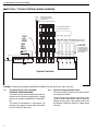
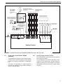
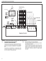
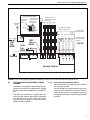
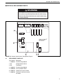
System Control Installation, Operation & Service Manual WARNING Improper installation, adjustment, alteration, service or maintenance can result in death, injury or property damage. Read the installation and operation manuals thoroughly before installing or servicing this equipment. Installation must be done by an electrician qualified in the installation of control systems for heating equipment. Installer Please take the time to read and understand these instructions prior to any installation. Installer must give a copy of this manual to the owner. Owner Keep this manual in a safe place to provide your serviceman with information should it become necessary. Roberts-Gordon Roberts-Gordon Canada Inc. 1250 William Street P.O. Box 44 Buffalo, New York 14240-0044 Telephone: 716.852.4400 Fax: 716.852.0854 Toll Free: 800.828.7450 241 South Service Road West Grimsby, Ontario L3M 1Y7 Canada Telephone: 905.945.5403 Fax: 905.945.0511 http://www.rg-inc.com © Copyright 2000 Roberts-Gordon Roberts-Gordon Oxford Street Bilston, West Midlands WV14 7EG UK Telephone: +44 (0) 1902 494425 Fax: +44 (0) 1902 403200 10091601NA Rev B 06/00 TABLE OF CONTENTS TABLE OF FIGURES 1. Introduction .............................................................. 1 ® 1.1 What is a ROBERTS GORDON System Control..................................................1 1.2 General Requirements...................................... 1 1.3 Check Installation Materials.............................. 1 1.4 Safety ................................................................1 2. Specifications .......................................................... 2 2.1 2.2 2.3 2.4 2.5 2.6 2.7 Material Specification........................................ Electrical Specification ...................................... Pump Specifications ........................................ Burner Electrical Ratings .................................. Outside Air Supply Blower ................................ Indicator Lights ................................................ Terminal Block Guide........................................ 2 2 2 2 2 2 2 Figure 1 Figure 2 Figure 3 Figure 4 Figure 5 Panel Layout.......................................................... 2 Terminal Block Guide ............................................ 2 System Control Cover Detail ................................ 3 Mounting Hole Layout............................................ 3 External Wiring Diagram EP 100 and EP 201 120V 1ph Pump .................. 4 Figure 6 External Wiring Diagram EP 301 120V 1ph Pump ...................................... 5 Figure 7 External Wiring Diagram EP 203 and EP 303 230V 3ph Pumps .................................................. 6 Figure 8 External Wiring Diagram 120V 1ph Pump with ...... Outside Air Blower.................................................. 7 Figure 9 System Control Troubleshooting Chart.................. 8 Figure 10 System Control Internal Components Diagram .................................................................. 9 3. Installation Instructions .......................................... 3 3.1 Preparation ...................................................... 3.2 Installing the System Control Panel.................. 3.3 Select the External Wiring Diagram for the Installation .................................................. 3.4 Important Voltage Selection.............................. 3 3 3 3 4. Typical External Wiring Diagrams .......................... 4 4.1 External Wiring Diagram EP 100 and EP 201 120V 1ph Pump .................................. 4 4.2 External Wiring Diagram EP 301 120V 1ph Pump ........................................................ 5 4.3 External Wiring Diagram EP 203 and EP 303 230V 3ph Pump ................................................ 6 4.4 Outside Air Blower External Wiring....................7 5. Troubleshooting ...................................................... 8 5.1 Sequence of Operation .................................... 8 6. Replacement Parts .................................................. 9 6.1 Replacement Parts List .................................... 9 6.2 Replacement Parts Instructions ......................10 7. The ROBERTS GORDON® System Control Warranty....................................................................11 © 2000 All rights reserved. No part of this work covered by the copyrights herein may be reproduced or copied in any form or by any means - graphic, electronic, or mechanical, including photocopying, recording, taping or information storage and retrieval systems - without the written permission of Roberts-Gordon. Printed in the U.S.A. SECTION SECTION 1: INTRODUCTION 1.1 1.3.4 The cable used for all wiring must be rated for line voltage up to 250V. Failure to follow these instructions will result in death or electrical shock. The system control, burners, pump and outside air blower must be electrically grounded in accordance with the National Electrical Code® ANSI/NFPA 70 - latest revision. Before proceeding with the installation of the ROBERTS GORDON® System Control, check the following points: 1.3 CHECK INSTALLATION MATERIALS 1.3.1 Thermostats Only use 24V thermostats with the ROBERTS GORDON® System Control. Do not use "power stealing" 24V thermostats. ROBERTS GORDON® offers a selection of low voltage thermostats approved for use with the system control. The thermostats measure the air temperature in the building. It is important that the thermostat is located in an area within the heated zone at occupant level. Do not place thermostat in an area shaded from the low-intensity, infrared heating system. Proving switch must be installed on all ROBERTS GORDON® systems to ensure safety and operation. System will not operate without proving switch. Failure to follow these instructions can result in product damage. 1.4 SAFETY Your Safety is Important to Us! This symbol is used throughout the manual to notify you of possible fire, electrical or burn hazards. Please pay special attention when reading and following the warnings. WARNING Installation, Service and Annual Inspection of controller must be done by an electrician qualified in the installation of control systems for heating equipment. Installation, Service and Annual Inspection must be done by a contractor qualified in the installation and service of gas-fired heating equipment. Read this manual carefully before installation, operation, or service of this equipment. Failure to follow these instructions can result in death, injury or property damage. Electrical Installation Materials A 1ph 16A, 120V power supply to the control panel must be installed in accordance with the most current National Electrical Code®, local codes and any site specific diagrams. Total load powered by the panel must not exceed 16A. Loads totaling more than 16A must be powered from an additional power supply circuit by the use of a load relay package. 1.3.3 CAUTION GENERAL REQUIREMENTS Failure to comply with the installation instructions will invalidate the limited warranty set out on Page 11, Section 7. 1.3.2 Vacuum Proving Switch A vacuum proving switch (P/N 90430600), preset at 1.7" w.c. is required for installation on the inlet of the pump. This switch is required to interlock the operation of the pump with the control panel. The System Control is capable of giving four zones of temperature control. The control will give power output to one pump. 1.2 INTRODUCTION the pump. The load relay package is required with the blower. See Page 7, Section 4, Figure 8, for wiring detail. WHAT IS A ROBERTS GORDON® SYSTEM CONTROL? The ROBERTS GORDON® System Control is an electronic controller designed for the control of CORAYVAC® and VANTAGE® EV systems. 1: Outside Air Supply Blower For optimum heater performance and safe heating conditions, inspect and maintain heater(s) before every heating season and as necessary. Also, know and maintain heater clearances to combustibles, see heater Installation, Operation and Service manual for further details. If you require additional manuals, contact your ROBERTS GORDON® independent distributor or Roberts-Gordon at (716) 852-4400 or (800) 8287450 in the U.S., (905) 945-5403 in Canada or at www.rg-inc.com. If used, the optional outside air blower is to be controlled in parallel with the pump. The blower incorporates a pressure switch which must be wired in series with the vacuum proving switch on 1 SYSTEM CONTROL INSTALLATION MANUAL SECTION 2: SPECIFICATIONS SYSTEM CONTROL Quality in Any Language TM LINE POWER PUMP POWER PROVING SWITCH ZONE 1 ZONE 2 ZONE 3 ZONE 4 U.S.A. Canada U.K. Internet 1.716.852.4400 1.905.945.5403 +44 (0) 1902 494425 www.rg-inc.com WARNING: Disconnect from electrical supply before removing this cover FIGURE 1 - Panel Layout 2.1 2.6 MATERIAL SPECIFICATION Enclosure Material: ABS (UL 94-5VA Rated) Weight: 1.1 lbs Dimensions: 7.9" x 11.4" x 2.4" (199 x 290 x 62 mm) Protection: Rating IP20 2.2 Pump Relay: Thermostats: 2.3 16A 120V 50/60Hz Single pole 4.4A 120V AC (resistive) Single pole 12A 120V AC (resistive) 1HP motor rated. Low voltage 12V DC 3. PROVING SWITCH, when lit, indicates that the proving switch is closed. 4. ZONE, when lit, indicates which zone relay is on. 2.7 TERMINAL BLOCK GUIDE Page 2, Section 2, Figure 2 is a guide to the terminal abbreviations. Ground Ground connection for burners and pump current: 3ph N/A 3.0A 4.2A BURNER ELECTRICAL RATINGS CORAYVAC® burners: 120V, 60Hz, 1ph 0.2A VANTAGE® EV burners: 120V, 60Hz, 1ph 0.2A 2.5 2. PUMP POWER, when lit, indicates the relay for power to the pump is energized. PUMP SPECIFICATIONS Full load 1ph EP 100 pump 1/3HP: 4.8A EP 200 series pumps 3/4HP: 6.6A EP 300 series pumps 1-1/2 HP: 16.0A 2.4 1. LINE POWER, when lit, indicates supply on to the panel. ELECTRICAL SPECIFICATION Supply: Zone Relay: INDICATOR LIGHTS (PAGE 2, SECTION 2, FIGURE 1) G N L PUMP Z1 Z2 OUTSIDE AIR SUPPLY BLOWER Z3 2.2A Run (Full load current) at 120V, 60Hz, 1ph, 2.2A Z4 T1 T2 T3 T4 PS 2 N L N L N L N L N L C C C C C Ground Neutral Live Power Supply Pump Live & Neutral Zone1 Burners Live & Neutral Zone 2 Burners Live & Neutral Zone 3 Burners Live & Neutral Zone 4 Burners Live & Neutral Thermostats 12V DC output Proving Switch FIGURE 2 - Terminal Block Guide SECTION SECTION 3: INSTALLATION 3.2.6 Installation of the System Control and the associated external electrical wiring must be completed by an electrician qualified in the installation of control systems for heating equipment. 3.1 4 x DIA. 0.2" (5mm) 6.85" (174 mm) Before installing the System Control, observe the following: Ensure that you have a copy of the site layout for the project that identifies clearly the separate zones. 3.1.2 Read Page 1, Section 1.3 carefully to ensure the correct installation materials are available. 3.2 INSTALLING THE SYSTEM CONTROL PANEL 3.2.1 3.2.2 INSTALLATION Fit the cable plate, provided with the System Control Panel, in the slot at the top of the System Control panel. PREPARATION 3.1.1 3: 10.7" (272 mm) FIGURE 4 - Mounting Hole Layout 3.3 SELECT THE EXTERNAL WIRING DIAGRAM FOR THE INSTALLATION Choose a mounting location for the System Control. It is advisable to choose a visible location near the pump. 3.3.1 Use Page 4, Section 4, Figure 5 for the external wiring of the burners, thermostats and pressure switch. Remove the cover of the System Control by removing the four securing screws. 3.3.2 Use the table below to select the correct pump external wiring diagram. Pump EP 100 EP 201 EP 301 EP 203 EP 303 See Page 3, Section 3, Figure 3 for cover detail. Pry the clip off using a flat blade screw driver in the groove (3). This will reveal the securing screw (2). Repeat this for each corner of the cover. Roberts-Gordon provides, at an additional cost, the following IEC contactor and enclosure required for the EP 301 pump, the part numbers are listed below. 1 2 3 5 For 120V AC Connection Description P/N 10050006 Contactor 120V AC EP 301 1ph 10001705 Contactor IEC 16A 120V AC 10001001 Enclosure IEC metal 8” x 5” x 5” Nema 1 Roberts-Gordon provides, at an additional cost, the following IEC contactor and overload starter package required for 3ph pumps, the contents are listed below: 4 ITEM 1 2 3 4 5 PN 10000701 10000700 NA NA 10090500 Supply Voltage Page Section Figure 120V 1ph 4 4 5 120V 1ph 4 4 5 120V 1ph 5 4 6 230V 3ph 6 4 7 230V 3ph 6 4 7 DESCRIPTION CLIP COVER PLASTIC SCREW M3X22 PAN HD BZP LEVER SLOT SECURING SCREW HOLE SYSTEM CONTROL LID ASSEMBLY FIGURE 3 - System Control Cover Detail 3.2.3 Disconnect the ribbon cable from the System Control panel board. Place the cover and the hardware in a safe place for refitting after the external wiring connections have been made. 3.2.4 Position the mounting hole location of the System Control per Figure 4, Section 3. 3.2.5 Remove the knockouts required for the conduit entry into the System Control panel. P/N Description 10050001 Starter 120V AC EP 203/303 3ph 10001001 Enclosure IEC metal 8" x 5" x 5" Nema 1 10001701 Contactor IEC 9A 120V AC 10001706 Overload IEC 1.6-5.0A 3ph 3.3.3 If an outside air blower is to be used with any of the above options, see Page 7, Section 4, Figure 8, or the external wiring diagram. 3.4 IMPORTANT: VOLTAGE SELECTION The System Control can be used with either 115V or 230V single phase. Ensure the voltage selector switch is set to 115V. See Page 9, Section 6, Figure 10, ITEM 2. 3 SYSTEM CONTROL INSTALLATION MANUAL SECTION 4: TYPICAL EXTERNAL WIRING DIAGRAMS Pump All burners must be connected to Ground (Not shown) Zone 1 Zone 2 Zone 3 Zone 4 Low voltage thermostats located in heated zone Zone Zone Zone Zone 4 1 2 3 120V 1ph 60HZ Pressure switch located at pump 120V 1ph 60HZ 12V DC Low voltage must be enclosed within the slotted cable trunking fitted inside the controller L Z4 C Z3 PS Z2 C Z1 T4 PUMP C N L T3 NL C NL T2 N L C N L T1 L Ground N Ground G N System Controller FIGURE 5 - External Wiring Diagram ROBERTS GORDON® EP 100 and EP 201 120V 1ph Pump 4.1 EP 100 OR EP 201 120V 1PH PUMP EXTERNAL WIRING DIAGRAM The external wiring diagram above shows the connections for four zones of system burners. System burners can be either CORAYVAC® or VANTAGE® EV. The zones are connected to a single pump. The external wiring diagram above shows connection to an EP 100 or EP 201 pump. 4 4.1.1 External wiring connection details The cable used for all the wiring must be rated for line voltage up to 250V. The low voltage circuit conforms with Class 2 separation of circuit requirements. National Electrical Codes® for wiring class 2 low voltage circuits must be followed. Disconnect electrical supply before servicing. SECTION EP 301 Pump IEC contactor P/N 10050006 rated for the EP 301 pump motor 6 120V 1ph 60 Hz 5 All burners must be connected to Ground (Not shown) Low voltage thermostats located in heated zone 2 M N 1 Zone Zone Zone 1 2 3 L Zone 4 Individual supply for pump rated for total full load current (See Page 2, Section 2.3 for details) Pressure switch located at pump L 12V DC Z4 C Z3 PS Z2 C Z1 T4 PUMP C NL T3 NL C NL T2 NL C NL T1 L N N Ground 4 3 G Ground TYPICAL EXTERNAL WIRING DIAGRAMS Zone 1 Zone 2 Zone 3 Zone 4 The power supply for each pump must be separate from the controller supply 120V 1ph 60 Hz Never directly connect the controller relay terminals to the pump motor. 4: System Control FIGURE 6 - External Wiring Diagram ROBERTS GORDON® EP 301 120V 1ph Pump 4.2 EP 301 120V 1PH EXTERNAL WIRING DIAGRAM The external wiring diagram above shows the connections for four zones of system burners. System burners can be either CORAYVAC® or VANTAGE® EV. The zones are connected to a single pump. The external wiring diagram above shows connection to an EP 301 1ph motor. 4.2.1 External wiring connection details The cable used for all the wiring must be rated for line voltage up to 250V. The low voltage circuit conforms with Class 2 separation of circuit requirements. National Electrical Codes® for wiring class 2 low voltage circuits must be followed. Disconnect electrical supply before servicing. 5 SYSTEM CONTROL INSTALLATION MANUAL 3ph Pump All burners must be connected to Ground (Not shown) Zone 1 Zone 2 Motor starter Zone 3 Zone 4 OL 230V 3ph 60HZ M Pressure switch located at pump 12V DC L Z3 Z4 T1 C Z2 PS Z1 C PUMP T4 NL C NL T3 NL C NL T2 NL C N L Ground Zone 4 120V 1ph 60HZ N 120V 1ph 60HZ Zone Zone Zone 3 1 2 G L3 L2 L1 Ground Low voltage thermostats located in heated zone System Control FIGURE 7 - External Wiring Diagram EP 203 and EP 303 230V 3ph Pump 4.3 EP 203 OR EP 303 230V 3PH PUMP EXTERNAL WIRING DIAGRAM The external wiring diagram above shows the connections for four zones of system burners. System burners can be either CORAYVAC® or VANTAGE® EV. The zones are connected to a single pump. The external wiring diagram above shows connection to an EP 203 or EP 303 3ph pump. 6 4.3.1 External Wiring Connection Details The cable used for all the wiring must be rated for line voltage up to 250V. The low voltage circuit conforms with Class 2 separation of circuit requirements. National Electrical Codes® for wiring class 2 low voltage circuits must be followed. Disconnect electrical supply before servicing. SECTION Typical wiring for Load Relay Package (P/N 05023000) Outside Air Blower Live out to the outside air blower Coil connections to Pump L & N Outputs from Control Panel 4: TYPICAL EXTERNAL WIRING DIAGRAMS All burners must be connected to Ground (Not shown) Pump Zone Zone Zone Zone 1 2 3 4 Live in Low voltage thermostats located in heated zone Pressure switch located at pump Relay Receptacle Back Plate L Z3 Z4 C Z2 PS Z1 C PUMP T4 NL C NL T3 NL C NL T2 NL C N T1 Ground 12V DC L Ground 120V 1ph 60HZ Pressure switch located at outside air blower 120V 1ph 60HZ N 120V 1ph 60HZ CR G N L Zone Zone Zone Zone 4 1 2 3 System Control FIGURE 8 - External wiring diagram ROBERTS GORDON® EP 100 or EP 201 120V 1ph Pump with outside air blower 4.4 OUTSIDE AIR BLOWER EXTERNAL WIRING DIAGRAM The external wiring diagram above shows the connections for four zones of system burners. System burners can be either CORAYVAC® or VANTAGE® EV. The zones are connected to a single pump. The external wiring diagram above shows connection to an EP 100 or EP 201 1ph motor. The diagram also shows the connection via a load relay to the optional outside air blower. 4.4.1 External Wiring Connection Details The cable used for all the wiring must be rated for line voltage up to 250V. The low voltage circuit conforms with Class 2 separation of circuit requirements. National Electrical Codes® for wiring class 2 low voltage circuits must be followed. Disconnect electrical supply before servicing. 7 SYSTEM CONTROL INSTALLATION MANUAL SECTION 5: TROUBLESHOOTING 5.1 SEQUENCE OF OPERATION a. On demand for heat, the panel will send power to the pump. The pump will begin operation. b. Once vacuum is established, the vacuum proving switch at the pump will close. c. The panel sends power to the burners. The burners will go through a 45 second purge and cycle time. Is the line power indicator on? See Page 2, Section 2, Figure 1. No Check the power supply to the system control panel. Is it on? Yes No d. Once flame is established, the heater will remain in operation until such time as either a lockout condition occurs or the heating is turned off by the thermostat. e. After the heating is turned off, the pump will continue operation for 2 minutes, post purge. Check the fuse. Is it OK? See Page 9, Section 6, Figure 10, (ITEM 1) Check the low voltage fuse. Is it OK? See Page 9, Yes Section 6, Figure 10, (ITEM 4) No No Replace fuse with P/N 10000202. Rectify power supply problem. Check if the ribbon cable Yes is securely located at both ends. Replace fuse with P/N 10000202. Yes Adjust thermostat set point to call for heat. Does the pump come on? Check the voltage selector, is it set to 115V? See No Page 9, Section 6, Yes Figure 10, (ITEM 2) No Set the selector to 115 V. Is external wiring to the pump OK? Yes Is the correct overload selected for the pump? See Page 2, Section 2.3. No No Rectify. Fit the correct overload. Yes Refer to burner troubleshooting in either the CORAYVAC ® or VANTAGE ® EV Installation, Operation and Service Manuals. Yes Does the zone light come on? Is the thermostat connected to the correct terminal at the Yes system control. See Page 4, Section 4, Figure 5. Does the proving switch No light come on? See Page 2, Section 2, Figure 1. Yes No Is external wiring to the proving switch OK? No Yes No Refer to burner troubleshooting in either the CORAYVAC ® or VANTAGE ® EV Installation, Operation and Service Manuals. Contact Roberts-Gordon. at www.rg-inc.com Rectify. Yes Do the burners in the zone come on? No Is external wiring to the zone OK? See Page 4, Section 4, Figure 5. Yes No Rectify. Yes Troubleshoot ends. Contact Roberts-Gordon. at www.rg-inc.com FIGURE 9 - System Control Troubleshooting Chart 8 Has the system been commissioned? Yes Refer to burner troubleshooting in either the CORAYVAC ® or VANTAGE ® EV Installation, Operation and Service Manuals. Refer to the burner start up ® No instructions in either the CORAYVAC or VANTAGE® EV Installation, Operation and Service Manuals. Rectify. SECTION 6: REPLACEMENT PARTS SECTION 6: REPLACEMENT PARTS WARNING Use only genuine ROBERTS GORDON ® replacement parts. Use of parts not specified by Roberts-Gordon voids warranty. Ground NL NL NL NL PUMP Z1 Z2 Z3 Z4 C C C C C NL T1 T2 T3 T4 PS L N G Failure to follow these instructions can result in death, injury or property damage. 1 ROBERTS GORDON® System Controller PN 10090100 2 3 4 5 FIGURE 10 - System Control Internal Components Diagram 6.1 REPLACEMENT PARTS LIST Part Number Description 1. 10000202 Fuse Anti Surge 500mA 2. NA Voltage Selector Switch 3. NA Transformer 4. 10000202 Fuse Anti Surge 500mA 5. 10000200 Fuse Fast Blow 315mA 6. 10000702 Cable Entry Plate not shown 7. 10000703 Clip Cover and Screw (4 pack) not shown 9 SYSTEM CONTROL INSTALLATION MANUAL 6.2 REPLACEMENT PARTS INSTRUCTIONS 6.2.4 WARNING This fuse protects the System Control circuit board. Electrical Shock Hazard If the fuse needs replacing, the following steps must be taken. Disconnect electrical supply before performing service or maintenance. Turn off the power to the System Control. Remove the clips and screws from the cover panel and remove the cover of the System Control. See Page 3, Section 3.2.2 for details. Failure to follow these instructions will result in death or electrical shock. 6.2.1 Disconnect the ribbon cable from the Main Board only, leaving the ribbon attached to the cover. 10000202 Fuse Anti Surge 500mA This fuse protects the System Control from power surges, lightning and incorrect wiring. Locate the fuse (Page 9, Section 6, Figure 10, ITEM 4) and remove the fuse with a fuse pulling tool. If the fuse needs replacing, the following steps must be taken. Turn off the power to the System Control. Replace with a new fuse rated to 500mA anti surge. Remove the clips and screws from the cover and remove the cover of the System Control. See Page 3, Section 3.2.2 for details. Reconnect the ribbon cable to the Main Board and replace cover. Disconnect the ribbon cable from the Main Board only, leaving the ribbon attached to the cover. Locate the fuse (Page 9, Section 6, Figure 10, ITEM 1) and remove the fuse with a fuse pulling tool. Replace with a new fuse rated at 500mA anti surge. Reconnect the ribbon cable to the Main Board and replace cover. 6.2.2 Voltage Selector Switch The voltage selector switch must display 115V for use in North America. 6.2.3 10000202 Fuse Anti Surge 500mA 6.2.5 10000200 Fuse Fast Blow 315mA This fuse protects the inputs connected to the System Control circuit board. If the fuse needs replacing, the following steps must be taken: Turn off the power to the System Control. Remove the clips and screws from the cover panel and remove the cover of the System Control. See Page 3, Section 3.2.2 for details. Disconnect the ribbon cable from the Main Board only, leaving the ribbon attached to the cover. Transformer Locate the fuse (Page 9, Section 6, Figure 10, ITEM 5) and remove the fuse with a fuse pulling tool. The transformer on the board cannot be replaced. Replace with a new fuse rated to 315mA fast blow. Reconnect the ribbon cable to the Main Board and replace cover. 10 SECTION SECTION 7: THE ROBERTS GORDON® SYSTEM CONTROL WARRANTY ROBERTS-GORDON WILL PAY FOR: For 36 months from the date of purchase by the original consumer or 18 months from date of shipment by RobertsGordon, whichever occurs first: we will provide, free of charge, replacement parts for any part of the ROBERTS GORDON® System Control that fails because of a manufacturing or material defect. ROBERTS GORDON® replacement parts are warranted for the period of the original ROBERTS GORDON® System Control Warranty. ROBERTS-GORDON WILL NOT PAY FOR: Service trips, service calls and labor charges. Shipment of replacement parts. Damage due to: Failure to install, operate or maintain the ROBERTS GORDON® System Control as directed in Installation, Operation and Service Manual. You must follow requirements printed in this manual. Misuse, abuse, neglect or modification of the ROBERTS GORDON® System Control in any way. Improper service, use of replacement parts or accessories that are not specified by Roberts-Gordon. Improper installation, or any relocation of the ROBERTS GORDON® System Control after initial installation. Incorrect supply, accident, fire, flood, acts of God or other casualty. Use of the ROBERTS GORDON® System Control for other than its intended purpose. Use of the ROBERTS GORDON® System Control in a corrosive atmosphere or any atmosphere containing contaminants. Shipping. Claim must be filed with carrier. WARRANTY IS VOID IF: 7: THE ROBERTS GORDON® SYSTEM CONTROL WARRANTY READ YOUR OPERATION AND INSTALLATION MANUALS If you have questions about your ROBERTS GORDON® System Control, contact your installing professional. Should you need replacement parts or have additional questions, call or write Roberts-Gordon: U.S.A. 1250 William Street P.O. Box 44 Buffalo, New York 14240-0044 Telephone: 716.852.4400 Fax: 716.852.0854 Canada 241 South Service Road, West Grimsby, Ontario L3M 1Y7 Telephone: 905.945.5403 Fax: 905.945.0511 On the web at: www.rg-inc.com Roberts-Gordon's liability, and your exclusive remedy, under this warranty or any implied warranty (including the implied warranties of merchantability and fitness for a particular purpose) is limited to providing replacement parts during the term of this warranty. Some jurisdictions do not allow limitations on how long an implied warranty lasts, so this limitation may not apply to you. There are no rights, warranties or conditions, expressed or implied, statutory or otherwise, other than those contained in this warranty. Roberts-Gordon shall in no event be responsible for incidental or consequential damages or incur liability for damages in excess of the amount paid by you for the ROBERTS GORDON® System Control. Some jurisdictions do not allow the exclusion or limitation of incidental or consequential damages, so this limitation or exclusion may not apply to you. This warranty gives you specific legal rights, and you may also have other rights which vary from jurisdiction to jurisdiction. You cannot prove original purchase date and required annual maintenance history. Roberts-Gordon shall not be responsible for failure to perform under the terms of this warranty if caused by circumstances out of its control, including but not limited to fire, flood, strike, government or court orders, unavailability of supplies, parts or power. No person is authorized to assume for Roberts-Gordon any other warranty, obligation or liability. The data plate and/or serial number are removed, defaced, modified or altered in any way. LIMITATIONS ON AUTHORITY OF REPRESENTATIVES: ® The ROBERTS GORDON System Control is not installed by a electrician qualified in the installation of control systems for heating equipment. ® The ROBERTS GORDON System Control is transferred. This warranty is nontransferable. Roberts-Gordon is not permitted to inspect the damaged controller and/or component parts. No representative of Roberts-Gordon, other than an Executive Officer, has authority to change or extend these provisions. Changes or extensions shall be binding only if confirmed in writing by Roberts-Gordon's duly authorized Executive Officer. 11