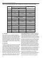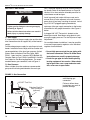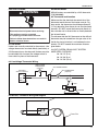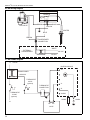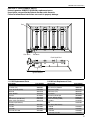
1
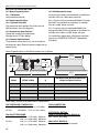
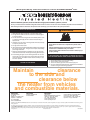
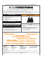
FOR YOUR SAFETY If you smell gas: 1. Open windows. 2. DO NOT try to light any appliance. 3. DO NOT use electrical switches. 4. DO NOT use any telephone in your building. 5. Leave the building. 6. Immediately call your local gas supplier after leaving the building. Follow the gas suppliers instructions. 7. If you cannot reach your gas supplier, call the Fire Department. WARNING Fire Hazard Do not store or use gasoline or other flammable vapors and liquids in the vicinity of this or any other appliance. ® ™ GordonGlo Gas-Fired, Unvented High-Intensity Infrared Heaters Installation, Operation & Service Manual GG-30 GG-60 GG-100 GG-130 GG-160 Failure to follow these instructions can result in death, injury or property damage. WARNING Improper installation, adjustment, alteration, service or maintenance can result in death, injury or property damage. Read the installation, operation and service manual thoroughly before installing or servicing this equipment. Installation must be done by a contractor qualified in the installation and service of gas-fired heating equipment or your gas supplier. Installer Please take the time to read and understand these instructions prior to any installation. Installer must give a copy of this manual to the owner. Owner Keep this manual in a safe place to provide your serviceman with information should it become necessary. Roberts-Gordon 1250 William Street P.O. Box 44 Buffalo, New York 14240-0044 Telephone: 716.852.4400 Fax: 716.852.0854 Toll Free: 800.828.7450 Quality in Any Language™ © Copyright 2002 Roberts-Gordon Roberts-Gordon Canada Inc. 76 Main Street West, Unit 10 Grimsby, Ontario, L3M 1R6 Canada Telephone: 905.945.5403 Fax: 905.945.0511 www.rg-inc.com P/N 142100NA Original 04/02 TABLE OF CONTENTS SECTION 1: Heater Safety ............................................1 1.1 Manpower Requirements ...................................1 SECTION 2: Installer Responsibility ...........................2 2.1 Wall Tag ..............................................................2 2.2 Corrosive Chemicals...........................................2 2.3 National Standards and Applicable Codes .........2 SECTION 3: Critical Considerations............................3 3.1 Required Clearances to Combustibles ...............3 SECTION 4: National Standards and Applicable Codes .............................................................................5 4.1 Gas Codes..........................................................5 4.2 Aircraft Hangars..................................................5 4.3 Public Garages ...................................................5 4.4 Electrical .............................................................5 SECTION 5: Major Components ..................................6 5.1 Standard Parts List .............................................6 SECTION 6: Heater Installation....................................7 6.1 Insulation ............................................................8 6.2 Ventilation ...........................................................8 SECTION 7: Gas Piping ..............................................10 7.1 Gas Supply .......................................................10 7.2 Gas Pressure....................................................10 SECTION 8: Wiring......................................................11 8.1 DSI Heater ........................................................11 8.2 Millivolt Heater ..................................................11 8.3 Thermostat and Location..................................11 8.4 Line Voltage Thermostat Wiring .......................11 8.5 Millivolt, Thermostat Wiring and Diagram .........11 8.6 DSI Wiring Diagram ..........................................12 8.7 DSI Ladder Diagram .........................................12 SECTION 9: Operation and Maintenance..................13 9.1 Operation-Spark Ignition System......................13 9.2 Operation-Millivolt System ................................13 9.3 Pre-Season Maintenance and Annual Inspection .........................................................13 9.4 Maintenance Checklist .....................................14 SECTION 10: Troubleshooting ...................................16 10.1 DSI..................................................................16 10.2 Millivolt ............................................................16 SECTION 11: Replacement Parts...............................17 11.1 DSI Replacement Parts ..................................17 11.2 Millivolt Replacement Parts ............................17 SECTION 12: Specifications ...................................... 18 12.1 Material Specifications ................................... 18 12.2 Heater Specifications ..................................... 18 12.3 Suspension Specifications ............................. 18 12.4 Controls Specifications .................................. 18 12.5 Altitude Specifications .................................... 18 SECTION 13: The ROBERTS GORDON® GG-SeriesTM Limited Warranty ........................................................ 19 © 2002 All rights reserved. No part of this work covered by the copyrights herein may be reproduced or copied in any form or by any means - graphic, electronic, or mechanical, including photocopying, recording, taping or information storage and retrieval systems - without the written permission of Roberts-Gordon. Printed in U.S.A. TABLE OF FIGURES Figure 1: Clearances to Combustibles ............................4 Figure 2: Installation Configurations................................7 Figure 3: Gas Connection ............................................10 Figure 4: DSI Test Set-up - Flame Rod Current ............16 SECTION 1: HEATER SAFETY SECTION 1: HEATER SAFETY Your Safety is Important to Us! This symbol is used throughout the manual to notify you of possible fire, electrical or burn hazards. Please pay special attention when reading and following the warnings in these sections. Installation, Service and Annual Inspection of heater must be done by a contractor qualified in the installation and service of gas-fired heating equipment. Read this manual carefully before installation, operation or service of this equipment. This heater is designed for heating nonresidential indoor spaces. Do not install in residential spaces. These instructions, the layout drawing, local codes and ordinances, and applicable standards that apply to gas piping, electrical wiring, venting, etc., must be thoroughly understood before proceeding with the installation. Thin sheet metal parts, such as the reflector portion of the heater and the various venting components, have sharp edges. To prevent injury, the use of work gloves is recommended. The use of gloves will also prevent the transfer of body oils from the hands to the surface of the reflector. Before installation, check that the local distribution conditions, nature of gas and pressure, and adjustment of the appliance are compatible. 1.1 Manpower Requirements To prevent personal injury and damage to the heater, two persons will be required for installation. 1 GG-SERIESTM INSTALLATION, OPERATION AND SERVICE MANUAL SECTION 2: INSTALLER RESPONSIBILITY The installer is responsible for the following: • To install the heater, as well as the gas and electrical supplies, in accordance with applicable specifications and codes. Roberts-Gordon recommends the installer contact a local building inspector or Fire Marshal for guidance. The model number is found on the burner and in the Installation, Operation and Service Manual. Write the largest clearance dimensions with permanent ink according to your model number in the open spaces on the tag. 2.2 Corrosive Chemicals CAUTION • To use the information given in a layout drawing and in the manual together with the cited codes and regulations to perform the installation. Do not use heater in an area containing corrosive chemicals. • To install the heater in accordance with the Clearances to Combustibles. Avoid the use of corrosive chemicals to ensure a longer life of the burner and other parts. • To furnish all needed materials not furnished as standard equipment. Failure to follow these instructions can result in property damage. • To plan location of supports. • To provide access to burners for servicing on all sides, for burner removal. • To provide the owner with a copy of this installation, operation and service manual. • To never use heater as support for ladder or other access equipment and never hang or suspend anything from heater. • To safely and adequately install heater attaching chain, rod or angle iron brackets through four mounting holes. • To ensure there is adequate air circulation around the heater and to supply air for combustion, ventilation and distribution in accordance with local codes. 2.1 Wall Tag * Halogenated Hydrocarbons are a family of chemical compounds characterized by the presence of halogen elements (fluorine, chlorine, bromine, etc.). These compounds are frequently used in refrigerants, cleaning agents, solvents, etc. If these compounds enter the air supply of the burner, the lifespan of the heater components will be greatly reduced. An outside air supply must be provided to the burners whenever the presence of these compounds is suspected. Warranty will be invalid if the heater is exposed to halogenated hydrocarbons. 2.3 National Standards and Applicable Codes TM A laminated wall tag is available for the GG-Series heater as a permanent reminder of the safety instructions and the importance of the required clearances to combustibles. Please contact Roberts-Gordon or your ROBERTS GORDON® independent distributor to obtain the wall tag. Since the GG-SeriesTM heater is available in DSI and millivolt, it is important to order the correct tag for the heater purchased. Affix the tag by peeling off the backing of the adhesive strips on the rear surface and position the tag on a wall near the GG-Series TM heater (e.g. thermostat or ROBERTS GORDON® BZC Controller). Copies of the wall tags (P/N 91037911 for DSI and P/N 91037913 for millivolt) are illustrated on the back cover. The appropiate copy of the wall tag can be affixed on the wall near the heater. To complete the tag you must know the model number of your heater. 2 Roberts-Gordon cannot be responsible for ensuring that all appropriate safety measures are undertaken prior to installation; this is entirely the responsibility of the installer. It is essential that the contractor, the sub-contractor, or the owner identifies the presence of combustible materials, corrosive chemicals or halogenated hydrocarbons* anywhere in the premises. All Appliances must be installed in accordance with the latest revision of the applicable standards and national codes. This refers also to the electric, gas and venting installation. Note: Additional standards for installations in Public Garages, Aircraft Hangars, etc. may be applicable. SECTION 3: CRITICAL CONSIDERATIONS SECTION 3: CRITICAL CONSIDERATIONS 3.1 Required Clearances to Combustibles Clearances are the required distances that combustible objects must be away from the heater to prevent serious fire hazards. Combustibles are materials, which may catch on fire and include common items such as wood, paper, rubber, fabric, etc. Maintain clearances to combustibles at all times for your safety. Clearances for all heater models are located on the heater and on Page 4, Figure 1 in this manual. Check the clearances on each heater for the model being installed to make sure the product is suitable for your application and the clearances are maintained. Read and follow the safety guidelines below: WARNING Fire Hazard Some objects will catch fire or explode when placed close to heater. Keep all flammable objects, liquids and vapors the required clearances to combustibles away from heater. Failure to follow these instructions can result in death, injury or property damage. • Keep gasoline or other combustible materials including flammable objects, liquids, dust or vapors away from this heater or any other appliance. • Maintain clearances from heat sensitive material, equipment and workstations. • Maintain clearances from vehicles parked below the heater. • Maintain clearances from swinging and overhead doors, overhead cranes, vehicle lifts, partitions, storage racks, hoists, building construction, etc. • In locations used for the storage of combustible materials, signs must be posted to specify the maximum permissible stacking height to maintain required clearances from the heater to the combustibles. Signs must be posted adjacent to the heater thermostat. In the absence of a thermostat, signs must be posted in a conspicuous location. • Consult local Fire Marshal, Fire Insurance Carrier or other authorities for approval of proposed installation when there is a possibility of exposure to combustible airborne materials or vapors. • Hang heater in accordance to the minimum suspension requirements on Page 7, Figure 2. 3 GG-SERIESTM INSTALLATION, OPERATION AND SERVICE MANUAL FIGURE 1: Clearances to Combustibles NOTE: Dimension "C" indicates the required clearances to combustibles, it DOES NOT indicate the required mounting height. A B E E 10° - 35° D 4 C Required Clearances to Combustibles (inches) B C D Model A E GG-30 30 36 48 11 16 GG-60 37 43 62 16 24 GG-100 46 68 95 25 37 GG-130 47 78 105 25 40 GG-160 55 82 109 27 44 Required Clearances to Combustibles (centimeters) B C D E Model A GG-30 77 92 122 28 41 GG-60 94 110 158 41 61 GG-100 117 173 242 64 94 GG-130 120 199 267 64 102 GG-160 140 209 277 69 112 SECTION 4: NATIONAL STANDARDS AND APPLICABLE CODES SECTION 4: NATIONAL STANDARDS AND APPLICABLE CODES 4.1 Gas Codes The type of gas appearing on the nameplate must be the type of gas used. Installation must comply with national and local codes and requirements of the local gas company. United States: Refer to National Fuel Gas Code, ANSI Z223.1 - latest revision, (same as NFPA Bulletin 54). Canada: Refer to CAN/CGA B149.1 and B149.2: Installation Codes for Gas Burning Appliances. 4.2 Aircraft Hangars Installation in aircraft hangars must be in accordance with the following codes: United States: Refer to Standard for Aircraft Hangars, ANSI/NFPA-409 - latest revision. Canada: Refer to Standard CAN/CGA B149.1 and B149.2. • In aircraft storage and servicing areas, heaters shall be installed at least 10' (3 m) above the upper surface of wings or of engine enclosures of the highest aircraft which may be housed in the hangar. The measurement shall be made from the wing or engine enclosure whichever is higher from the floor, to the bottom of the heater. • In shops, offices and other sections of aircraft hangars communicating with aircraft storage or servicing areas, heaters shall be installed not less than 8' (2.4 m) above the floor. • Suspended or elevated heaters shall be so located in all spaces of aircraft hangars that they shall not be subject to injury by aircraft, cranes, movable scaffolding or other objects. Provisions shall be made to assure accessibility to suspended heaters for recurrent maintenance purposes. 4.3 Public Garages Installation in garages must be in accordance with the following codes: United States: Standard for Parking Structures NFPA-88A - latest revision or the Standard for Repair Garages, NFPA 88B - latest revision. Canada: Refer to CAN/CGA B149.1 and B149.2: Installation Codes for Gas Burning Appliances. • Heaters must not be installed less than 8' (2.4m) above the floor. Minimum clearances to combustibles must be maintained from vehicles parked below the heater. • When installed over hoists, minimum clearances to combustibles must be maintained from the upper most point of objects on the hoist. 4.4 Electrical The heater must be electrically grounded in accordance with the following codes: United States: Refer to National Electrical Code®, ANSI/NFPA-70 - latest revision. Wiring must conform to the most current National Electrical Code®, local ordinances, and any special diagrams furnished. Canada: Refer to Canadian Electrical Code, CSA C22.1 Part 1 - latest revision. 5 GG-SERIESTM INSTALLATION, OPERATION AND SERVICE MANUAL SECTION 5: MAJOR COMPONENTS 5.1 Standard Parts List Table 1: DSI Carton Contents Part No. Description GG-60 GG-100 GG-130 GG-160 042XXXXX Burner Assembly (Rate and Fuel Varies) 1 1 1 1 1 90439900 Transformer 1 1 1 1 1 91317300 Terminals 2 2 2 2 2 142100NA Installation, Operation and Service Manual 1 1 1 1 1 GG-30 GG-60 1 1 Table 2: Millivolt Carton Contents Part No. Description 043XXXXX 6 GG-30 Burner Assembly (Rate and Fuel Varies) GG-100 GG-130 GG-160 1 1 1 90440000 Thermostat 1 1 1 1 1 142100NA Installation, Operation and Service Manual 1 1 1 1 1 SECTION 6: HEATER INSTALLATION SECTION 6: HEATER INSTALLATION Do not locate the gas or electric supply lines directly over the path of the flue products from the heater. WARNING The heater must be installed in a location that is readily accessible for servicing and no restriction of air flow to the inlet of the heater’s venturi tubes can occur. Suspension Hazard Hang heater with materials with a minimum working load of 175 lbs (80 kg). The heaters must be installed with clearances to combustibles as indicated on the rating plate and in this instruction manual. Failure of the supports can result in death, injury or property damage. The minimum and maximum gas inlet pressures must be maintained as indicated on the rating plate. To ensure your safety, and comply with the terms of the warranty, all units must be installed in accordance with these instructions. The gas or the electrical supply lines must not be used to support the heater. The heater has four mounting holes, one at each corner, for attaching chain, rod or angle iron brackets. Typical installation configurations are shown in Figure 2. FIGURE 2: Installation Configurations Typical Suspension Details Concrete Beam Beam Clamp Anchor Screw Hook (3/8") Chain size 3/16" minimum Rod (3/8") Wood Beam Locknut Washers Snap Hooks Turnbuckle Not Included Snap Hooks Heater Side View Description Snap Hook (not included) Part Number 91903300 10° - 35° Front View 10.8" (27 cm) Min 10° 2.7" (7 cm) Max 35° 7 GG-SERIESTM INSTALLATION, OPERATION AND SERVICE MANUAL Table 3: Recommended mounting height and approximate coverage for indoor spot heating. Model Mounting Height Minimum Maximum +30°F Design Temperature 100 BTU/Hr./sq.ft. GG-30 10’ (3m) 12’ (3.6m) 300 sq. ft. GG-60 16’ (5m) 18’ (5.4m) 600 sq. ft. GG-100 19’ (6m) 23’ (7m) 900 sq. ft. GG-130 22’ (6.7m) 28’ (8m) 1200 sq. ft. GG-160 25’ (7.6 m) 32’ (9.7 m) 1500 sq. ft. 0°F Design Temperature 250 BTU/Hr./sq.ft. GG-30 8’ (2.4m) 9’ (2.7m) 120 sq. ft. GG-60 11’ (3.3m) 13’ (4m) 240 sq. ft. GG-100 13’ (4m) 15’ (4.5m) 360 sq. ft. GG-130 16’ (5m) 18’ (5.4m) 480 sq. ft. GG-160 20’ (6 m) 24’ (7.3 m) 600 sq. ft. -30°F Design Temperature 6.1 Insulation Approx. Coverage 420 BTU/Hr./sq.ft. GG-30 - - - GG-60 9’ (2.7m) 11’ (3.3m) 142 sq. ft. GG-100 11’ (3.3m) 13’ (4m) 210 sq. ft. GG-130 12’ (3.6m) 14’ (4.2m) 285 sq. ft. GG-160 16 (4.8 m) 20 (6 m) 360 sq. ft. these dilution requirements. However, in tightly constructed buildings, where insufficient air movement Roof insulation or built-up roofing is required for metal decks to maintain inside surface temperatures exists, induced air displacement is required. This may be accomplished by either gravity or mechanical above the dew point of air. If the roof is bare metal, means. Where natural (gravity) ventilation is provided not insulated, the inside surface temperature may become cold enough for moisture to form. Vapor bar- for exhaust, the openings must be distributed above the heaters (preferably at the peak of the roof) and riers must be applied to insulation. Tears or gaps must be sealed. Insulation without a vapor barrier is the areas of openings shall not be less than 300 square inches for every 100,000 BTU input. Provinot acceptable. sions must be made to provide sufficient fresh air 6.2 Ventilation inlet area and exhaust air outlet area to accomplish Ventilation of upper levels of the space to be heated the displacement. This is essential in providing a balis required to supply combustion air to the heaters anced system to avoid negative building pressures and sufficiently dilute the products of combustion. which cause excessive infiltration, unfavorable drafts This also prevents excessive humidity build-up. The and effect efficient combustion of infrared heaters. minimum intake and exhaust air openings shall proMechanical exhausters are preferred and are typivide for not less than 400 CFM for every 100,000 cally mounted at high points in the building where BTU input except that the infiltration area may be included in the intake area. The exhaust fan must be stagnant air can accumulate under the deck. Local codes may require that mechanical exhausters interlocked with the heater thermostat. Check with be interlocked with the heaters to enable both to local codes for requirements. Many large industrial operate simultaneously. Other codes may allow buildings have sufficient air movement to satisfy 8 SECTION 6: HEATER INSTALLATION control of exhausters with a ceiling mounted humidistat. Exhausters then operate when relative humidity rises above the humidistat setting. Since the combustion process increases the relative humidity, this is a feasible method of controlling humidity. 9 GG-SERIESTM INSTALLATION, OPERATION AND SERVICE MANUAL SECTION 7: GAS PIPING WARNING Fire Hazard Tighten gas line fittings to connect gas supply according to Figure 3. Failure to follow these instructions can result in death, injury or property damage. 7.1 Gas Supply It is important that the gas supply pipe and the electrical connections do not support any of the heater’s weight. Provide adequate gas supply for rated input of each heater. Installation must comply with local codes and recommendations of the local gas company. United States: Refer to National Fuel Gas Code, ANSI Z223.1 - latest revision, (same as NFPA Bulletin 54). Canada: Refer to Can 1-B149.1 and B149.2: Installation Codes for Gas Burning Appliances. For recommended heater gas connection, refer toFigure 3. 7.2 Gas Pressure When a higher than the maximum recommended gas pressure is being maintained at the main gas line, a separate regulator must be installed ahead of the heater. Refer to the Specifications on Page 18, Section 12 for the maximum allowable pressure for stated heater model and gas. Install a ground joint union with brass seat and a manual shut-off valve adjacent to the unit for emergency shut-off and easy servicing of controls, including a 1/8" NPT plugged tapping immediately upstream of the gas supply connection to the heater, accessible for test gauge connection. See Figure 3 below. A plugged 1/8" NPT Test point is located on the heater gas control. See heater rating plate for minimum gas supply pressure "For the Purpose of Input Adjustment." On a multiple heater installation, it may be possible to use one large capacity regulator or an individual regulator for each heater. • Do not high pressure test the gas piping with the burner connected. Failure to follow these instructions can result in property damage. • Check the gas pipe for leaks before placing heating equipment into service. When checking for gas leaks, use a soap and water solution; never use an open flame. FIGURE 3: Gas Connection 1/8" NPT Test Port Shut-Off Valve Stainless Steel Flex Gas Connector (optional) 1/8" NPT Test Port Drip Leg Cap 10 Ground Joint Union Hold gas valve securely while making gas connection. Failure to follow these instructions can result in product damage. SECTION 8: WIRING SECTION 8: WIRING 8.2 Millivolt Heater WARNING Millivolt heaters are controlled by a 24V thermostat (P/N 90440000). 8.3 Thermostat and Location Electrical Shock Hazard Disconnect electrical power before servicing. This appliance must be connected to a properly grounded electrical source. Failure to follow these instructions can result in death or electrical shock. 8.1 DSI Heater Heaters are normally controlled by thermostats. Line voltage thermostats are wired directly (see below); a 24V thermostat may also be used. Heaters may also be controlled with a manual line voltage switch or timer switch in place of the thermostat. Make sure that the electrical characteristics of the thermostat match those of the heater controls. For best results, the thermostat should be positioned 5’ (1.5 m) above the floor where air can circulate freely around it. DO NOT mount the thermostat directly to the cold-side wall, in direct drafts or directly beneath the infrared heater. The distance that the 24V thermostat or the millivolt thermostat may be located from the gas valve is limited by the size of wire that is run between the two devices. DO NOT exceed the maximum distance given below: 24 VOLT SYSTEM OR MILLIVOLT SYSTEM WIRE SIZES / DISTANCE: No. 18 / 15’ (5 m) No. 16 / 30’ (9 m) No. 14 / 50’ (15 m) 8.4 Line Voltage Thermostat Wiring LINE VOLTAGE THERMOSTAT (Optional) 24V TRANSFORMER 24V THERMOSTAT (Optional) 120V-60Hz SUPPLY CIRCUIT L1 L2 N GND H GND BURNER 8.5 Millivolt, Thermostat Wiring and Diagram Gas Valve Th PP Th PP Power Pile 11 GG-SERIESTM INSTALLATION, OPERATION AND SERVICE MANUAL 8.6 DSI Wiring Diagram GAS VALVE BROWN V1 S1 V2/GND TH IGNITION MODULE BLACK YELLOW IGNITER BLUE YELLOW TRANSFORMER CONNECTION WHITE EXTERNAL TRANSFORMER 120 VAC BLACK 8.7 DSI Ladder Diagram L1 120VAC IGNITION MODULE TH TRANSFORMER 120/24VAC THERMOSTAT 24VAC (optional) V1 THERMOSTAT CONNECTION S1 THERMOSTAT 120VAC V2/GND (optional) SENSE L2 MV MV VALVE 12 SPARK SECTION 9: OPERATION AND MAINTENANCE SECTION 9: OPERATION AND MAINTENANCE 9.1 Operation-Spark Ignition System The GG-SeriesTM heater is equipped with a spark ignition system. When the system calls for heat, the following sequence occurs: Before lighting, turn gas valve OFF and wait five minutes for unburned gas to vent from heater. After five minutes: Turn knob on gas control counterclockwise to "PILOT." 1. After a 45 second pre-purge, the ignition module opens the gas valve and energizes the electrode. Push in control knob all the way and hold in. Immediately light the pilot with a match. Continue to hold the 2. When the flame is established, the sparking control knob in for about one minute after the pilot is sequence ceases. lit. Release knob and it will pop back up. Pilot should 3. If the flame is not established during the ignition remain lit. If it goes out, repeat Section 9.2.2. sequence, the ignition module closes the gas • If knob does not pop up when released, stop and valve and purge begins. The ignition module will immediately call your service technician or gas try 2 additional times for ignition (with purge supplier. between). If ignition is not established, the module will lock-out. NOTE: After 1 hour, the module will re-set automatically and return to steps 1,2 and 3. 5. If a flame is detected, the gas valve remains open. When the thermostat is satisfied, power (120 or 24 VAC) is shut off and the gas valve closes. 9.1.1 To Shut Off Heater Turn thermostat to lowest setting. Turn OFF electric current to heater. Turn OFF manual gas valve. 9.1.2 To Start Heater Before lighting, turn gas valve and electric current OFF and wait five minutes for unburned gas to vent from heater. After five minutes: Turn ON manual gas valve. Turn ON electric current to heater. • If pilot will not stay lit after several tries, turn the gas control knob to "OFF" and call your service technician or gas supplier. Turn gas control knob counterclockwise to "ON." Set thermostat to desired setting Once heater is operating, keep away from the heater. Do not touch any part of the heater because it is very hot. 9.3 Pre-Season Maintenance and Annual Inspection To ensure your safety and years of trouble-free operation of the heating system, service and annual inspections must be done by a contractor qualified in the installation and service of gas-fired heating equipment. Disconnect gas and electric supplies before performing service or maintenance. Allow heater to cool before servicing. Turn thermostat above room temperature and burner To obtain the maximum performance from your should light automatically. heater each year, we recommend the following be Set thermostat to desired temperature. performed at the start of the heating season. 9.2 Operation-Millivolt System 9.2.1 To Shut Off Heater Turn thermostat to lowest setting. Push in gas control knob slightly and turn clockwise to "OFF." NOTE: Knob cannot be turned from "PILOT" to "OFF" unless knob is pushed in slightly. Do not force. 1. With an air hose regulated to 25 PSIG, blow off any dust and dirt that has accumulated on the heater. 2. From the front of the heater, direct the air hose from a distance of approximately 12" (30 cm) over the entire exposed area of the ceramic tile. 3. Do not insert the air hose into the inlet of the venturi tube. 9.2.2 To Start Heater 4. Remove, clean and re-install each gas orifice. 13 GG-SERIESTM INSTALLATION, OPERATION AND SERVICE MANUAL 5. If additional service to the heater is required, contact the factory or your local representative. Before every heating season, a contractor qualified in the installation and service of gas-fired heating equipment must perform a thorough safety inspection of the heater. For safety and best performance, the gas, electrical, thermostat connections, suspensions and overall heater condition are some of the areas requiring inspection. NOTE: Gas flow and burner ignition are among the first things that should be inspected. Please See Page 14, Section 9.4 for suggested items to inspect. 9.4 Maintenance Checklist Installation, Service and Annual Inspection of the heater must be done by a contractor qualified in the installation and service of gas-fired heating equipment. Read this manual carefully before installation, operation, or service of this equipment. The Vicinity of the Heater Do not store or use flammable objects, liquids or vapors near the heater. Immediately remove these items if they are present. See Page 3, Section 3 Vehicles and Other Objects Maintain the clearances to combustibles. Do not hang anything from, or place anything on, the heater. Make sure nothing is lodged between the reflector, pods, and gas manifold or laying on top of the heater. Immediately remove objects in violation of the clearances to combustibles. See Page 3, Section 3 Reflector Make sure there is no dirt, sagging, cracking or distortion. Do not operate if there is sagging, cracking or distortion. Clean surface with a damp cloth. Gas Line Check for gas leaks. See Page 10, Section 7. Orifice Clear of obstructions (even spider webs will cause problems). Carefully remove any dust and debris from the burner. Direct Spark Igniter Replace if cracked or if rod shows signs of wear. Thermostat There should be no exposed wire or damage to the thermostat. See Page 11, Section 8 14 SECTION 9: OPERATION AND MAINTENANCE Suspension Points Make sure the heater is properly secured on all hanging points. Look for signs of wear on the chain or ceiling. See Page 3, Section 3 and Page 7, Figure 2. Wire Mesh and Support Rods Make sure the support rods are in their original position and have not moved out of the locating holes. The rods are affixed with a pushnut at the bottom of the heater. The wire mesh is affixed on two places to the support rods. Ceramic and Burner Pods Make sure that there are no cracks in the ceramics. Make sure the gaskets are between the ceramics, and between the ceramics and metal pod. 15 GG-SERIESTM INSTALLATION, OPERATION AND SERVICE MANUAL SECTION 10: TROUBLESHOOTING 10.1 DSI 10.1.1 No Spark 10.1.4 Flame Rod Current Test 1. If the ignition fails to spark after completion of the purge cycle, ensure line voltage is present at the transformer. The proper flame rod-to-ground area ratio cannot always be determined by visual examination or physical measurement. A positive means of checking the installation is to measure the flame rod current 2. Measure output of the transformer - is it 24V? under actual firing conditions. It is definitely recom3. Interrupt line power for 10 seconds and re-estabmended that the installer measure the current flow lish power to reset the ignition module. If spark is between the lead of the flame rod unit and the terminot present after purge, replace the ignition modnal in the control terminal board (see Figure 4). Meaule. sure the current with a DC Micro-Ammeter or equal. 10.1.2 Spark Gap We recommend a steady output of 0.9 µA or more. A 1. Insure that the flame rod is not grounding and steady flow of current in this amount under actual firthat the spark gap is set between 1/8" (3 mm) ing conditions will generally indicate and 3/16" (5 mm). adequate flame. 10.1.3 Burner Does Not Stay Lit 1. Read all control data sheets supplied with this heater. 1. Ensure flame sensor is not grounding. 2. Measure flame signal - is it minimum 0.9 µA? See Section 10.1.4 and Figure 4. 3. Clean flame sensor and check sensor wiring. 4. Verify that the burner is wired per the circuit diagram as polarity of supply connections is critical. 5. Ensure adequate gas supply pressure. 2. Check flame rod for any contact to heater parts. Flame rod must be free of any contact to heater. Contact with heater will short circuit flame rod. 3. Cracked porcelain on flame rod will short circuit sensor. Replace flame rod. 10.2 Millivolt 10.2.1 Pilot Burner/Main Burner Fails to Light 1. Ensure adequate gas supply pressure. 2. Ensure pilot flame. 3. Ensure correct manifold gas pressure is present when valve is energized. FIGURE 4: DSI Test Set-up - Flame Rod Current IGNITION MODULE MICRO-AMMETER FC+ FC- 16 SECTION 11: REPLACEMENT PARTS SECTION 11: REPLACEMENT PARTS Use only genuine ROBERTS GORDON ® replacement parts. Use of parts not specified by Roberts-Gordon voids warranty. Failure to follow these instructions can result in property damage. Pod ON OFF Gas Valve Electrode Push Nut & Rod TH V1 S1 V2/GND THERMOSTAT CONNECTION Ignition Module 11.1 DSI Replacement Parts Description Gas Valve (Natural) Gas Valve (LP) Burner Assembly (POD) Electrode Ignition Module Push Nut Rod Wire Harness (Not Shown) Ignition Cable (Not Shown) Wire Mesh (Not Shown): GG-30 GG-60 GG-100 GG-130, GG-160 11.2 Millivolt Replacement Parts Part Number 90032503 90032502 04010000 90427410 90439500 91120104 91613100 04091000 90427710 91613301 91613302 91613303 91613304 Description Gas Valve (NAT) Millivolt Gas Valve (LP) Millivolt Pilot Burner (NAT) Pilot Burner (LP) Thermopile Thermostat Powerpile Bracket, Millivolt Ignitor Burner Assembly (POD) Push Nut Rod Wire Mesh (Not Shown): GG-30 GG-60 GG-100 GG-130, GG-160 Part Number 90068500 90068700 90311900 90311801 90311800 90440000 04030100 04010000 91120104 91613100 91613301 91613302 91613303 91613304 17 GG-SERIESTM INSTALLATION, OPERATION AND SERVICE MANUAL SECTION 12: SPECIFICATIONS 12.1 Material Specifications 12.1.1 Reflectors 12.5 Altitude Specifications All natural gas heaters are intended for installation at altitudes from 0 to 4,500’ above sea level. .040 polished aluminium All L.P. burners with part numbers 042030LP through 042130LP are intended for installation at altitudes from 0 to 2,000’ above sea level. 12.2 Heater Specifications 12.2.1 Ignition Controller Fully automatic spark ignition with safety shut-off. (Millivolt heater uses standing pilot.) All L.P. burners with part numbers042030LPHA through 042130LPHA are intended for installation at altitudes from 2,000’ to 4,500’ above sea level. 12.3 Suspension Specifications Galvanized straight link welded chain. Working load of 175 lbs (80 kg). For installations higher than 4,500’ above sea level consult your ROBERTS GORDON ® Independent Distributor. 12.4 Controls Specifications Time switches, thermostats, etc. can be wired into the electrical supply. External controls supplied as an optional extra. General Specifications for GG-Series heaters are as follows. 16.6" (42 cm) 4.5" (11 cm) 10.3" (26 cm) 8.3" (21 cm) 22.5" (57 cm) A Heat Input Rate Model (BTUH X1000) A Recommended Minimum Mounting Height for Space Heating* GG-30 30 15.6" (39.6 cm) 8’ - 10’ (2.4 - 3m) GG-60 60 22.3" (56.6 cm) 10’ - 12’ (3 - 3.6m) GG-100 100 29.1" (74 cm) 12’ - 15’ (3.6 - 4.5m) GG-130 130 35.8 (91 cm) 12’ - 15’ (3.6 - 4.5m) GG-160 160 35.8" (91 cm) 15’+ (4.5m) *See Page 3, Section 3 for clearrances to combustibles. GAS PRESSURE AT MANIFOLD: Natural Gas: All Models 6.0" w.c. (14.9 mbar) LP Gas: All Models 11.0" w.c. (26.1 mbar) GAS INLET PRESSURE: Natural Gas: 7.0" w.c. (17.4 mbar) 14.0" w.c. (34.8 mbar) LP Gas: 12.0" w.c. (27.4 mbar) 14.0" w.c. (34.8 mbar) 18 PIPE CONNECTION: 1/2" NPT (All Models) ELECTRICAL RATING (DIRECT SPARK IGNITION MODELS): Minimum Maximum Minimum Maximum 24V - 60 Hz., 0.67 Amp (MILLIVOLT MODELS): No outside source of power required. SECTION 13: THE ROBERTS GORDON® GGSERIESTM LIMITED WARRANTY ROBERTS-GORDON WILL PAY FOR: ® ROBERTS GORDON warrants to the original owner-user that this ROBERTS GORDON® product will be free from defects in material and workmanship. This warranty is limited to twelve (12) months from the date of purchase by the original consumer, or eighteen (18) months from date of shipment by Roberts-Gordon, whichever occurs first. The data plate and/or serial number are removed, defaced, modified or altered in any way. The ROBERTS GORDON® GG-SeriesTM is transferred. This warranty is nontransferable. Roberts-Gordon is not permitted to inspect the damaged burner and/or component parts. READ YOUR INSTALLATION MANUAL ROBERTS GORDON® warrants the ceramic grid will be free from defects in material and workmanship. This warranty is limited to ten (10) years from the date of shipment by Roberts-Gordon. If you have questions about your heater, contact your installing professional. Should you need Replacement Parts or have additional questions, call or write RobertsGordon: ROBERTS-GORDON WILL NOT PAY FOR: Canada 76 Main Street West, Unit 10 Grimsby, Ontario L3M 1R6 905.945.5403 Service trips, service calls and labor charges. Shipment of replacement parts. Damage due to: Failure to install, operate or maintain the ROBERTS GORDON® GG-SeriesTM as directed in Installation, Operation and Service Manual. You must follow requirements printed in this manual. Misuse, abuse, neglect or modification of the ROBERTS GORDON® GG-SeriesTM in any way. U.S.A. 1250 William Street P.O. Box 44 Buffalo, New York 14240-0044 716.852.4400 On the web at: www.rg-inc.com Improper service, use of replacement parts or accessories that are not specified by Roberts Gordon. Improper installation, or any relocation of the ROBERTS GORDON® GG-SeriesTM after initial installation. Incorrect supply, accident, fire, flood, acts of God or other casualty. Use of the ROBERTS GORDON® GG-SeriesTM for other than its intended purpose. Use of the ROBERTS GORDON® GG-SeriesTM in a corrosive atmosphere or any atmosphere containing contaminants. Shipping. Claim must be filed with carrier. Use of the ROBERTS GORDON® GG-SeriesTM in the vicinity of combustible or explosive materials. Any defect in the ROBERTS GORDON® GG-SeriesTM arising from a drawing, design or specification supplied by or on behalf of the consumer. Failure of parts not manufactured by Roberts Gordon in respect of any claim where the total price of the goods has not been paid. WARRANTY IS VOID IF: Roberts-Gordon’s liability, and your exclusive remedy, under this warranty or any implied warranty (including the implied warranties of merchantability and fitness for a particular purpose) is limited to providing replacement parts during the term of this warranty. Some jurisdictions do not allow limitations on how long an implied warranty lasts, so this limitation may not apply to you. There are no rights, warranties or conditions, expressed or implied, statutory or otherwise, other than those contained in this warranty. Roberts-Gordon shall in no event be responsible for incidental or consequential damages or incur liability for damages in excess of the amount paid by you for the ROBERTS GORDON® GG-SeriesTM . Some jurisdictions do not allow the exclusion or limitation of incidental or consequential damages, so this limitation or exclusion may not apply to you. This warranty gives you specific legal rights, and you may also have other rights which vary from jurisdiction to jurisdiction. Roberts-Gordon shall not be responsible for failure to perform under the terms of this warranty if caused by circumstances out of its control, including but not limited to fire, flood, strike, government or court orders, unavailability of supplies, parts or power. No person is authorized to assume for Roberts-Gordon any other warranty, obligation or liability. LIMITATIONS ON AUTHORITY OF REPRESENTATIVES: No representative of Roberts-Gordon, other than an The ROBERTS GORDON® GG-SeriesTM is not installed by Executive Officer, has authority to change or extend these a contractor qualified in the installation and service of gas- provisions. Changes or extensions shall be binding only if fired heating equipment. confirmed in writing by Roberts-Gordon’s duly authorized Executive Officer. You cannot prove original purchase date and required annual maintenance history. GG-SERIESTM INSTALLATION, OPERATION AND SERVICE MANUAL 20 Millivolt Ignition Wall Tag - Attach this information to a wall near the ROBERTS GORDON® heater. ® Read the Installation, Operation, and Service Manual thoroughly before installation, operation, or service. Know your model number and installed configuration. Model number is found on the burner and in the Installation, Operation and Service Manual. Write the largest clearance dimensions with permanent ink according to your model number in the open spaces below. WARNING OPERATING INSTRUCTIONS 1. STOP! Read all safety instructions on this information sheet. 2. Turn gas valve to OFF and wait five minutes for unburned gases to vent from heater. 3. Turn the control knob on the gas valve to the PILOT position. Push in control knob and light pilot with a match while continuing to depress knob. 4. Hold knob in for one minute, millivolt generator will heat sufficiently to keep the pilot valve open. 5. Turn gas control knob to ON. 6. Upon a call for heat, the millivolt thermostat contacts close, completing the circuit to the gas valve. The gas valve will open and standing pilot will light the heater. 7. Once the millivolt thermostat is satisfied, the main gas valve will close and the heater shuts off leaving the standing pilot valve open. 8. If the standing pilot goes out, the millivolt generator will cool and interrupt the circuit to the pilot valve. Both the pilot and main gas valves are closed. The heater remains inactive until steps 1, 2, 3 and 4 are repeated. TO TURN OFF THE HEATER 1. Set the thermostat to off or the lowest setting. Fire Hazard Some objects can catch fire or explode when placed close to heater. Keep all flammable objects, liquids and vapors the required clearances to combustibles away from heater. Failure to follow these instructions can result in death, injury or property damage. IF THE HEATER WILL NOT OPERATE, TO ENSURE YOUR SAFETY, FOLLOW THESE INSTRUCTIONS TO SHUT DOWN YOUR HEATER 1. 2. 3. 4. Set the thermostat to off or the lowest setting. Turn off electric power to the heater. Turn off the manual gas valve in the heater supply line. Call your registered installer/contractor qualified in the installation and service of gas-fired heating equipment. Maintain ???? cm clearance to the side and ???? cm clearance below the heater from vehicles and combustible materials. Roberts-Gordon 1250 William Street P.O. Box 44 Buffalo, NY 14240-0044 USA Telephone: 716.852.4400 Fax: 716.852.0854 Toll Free: 800.828.7450 Roberts-Gordon Telephone: 905.945.5403 Fax: 905.945.0511 Roberts-Gordon Oxford Street Bilston, West Midlands WV14 7EG UK Telephone: +44(0) 1902 494425 Fax: +44(0) 1902 403200 E-mail: [email protected] E-mail: [email protected] Service Telephone: +44(0) 1902 498733 Service Fax: +44(0) 1902 401464 Export Telephone: +44(0) 1794 521562 Export Fax: +44(0) 1794 521387 Installation Code: ROBERTS GORDON® products are to be installed only in accordance with local laws, codes and regulations, and only by a contractor qualified in the installation and service of gas-fired heating equipment. For optimum product performance and safety, installation, service and annual inspections must be completed by a contractor qualified in the installation and service of gas-fired heating equipment. © 2002 ROBERTS GORDON® All rights reserved. No part of this work covered by the copyrights herein may be reproduced or copied in any form or by any means - graphic, electronic, or mechanical, including photocopying, recording, taping or information storage and retrieval systems - without the written permission of Roberts-Gordon. www.rg-inc.com Printed in the U.S.A. P/N 91037913 Direct Spark Ignition Wall Tag - Attach this information to a wall near the ROBERTS GORDON® heater. ® I n f r a r e d H e a t i n g Read the Installation, Operation, and Service Manual thoroughly before installation, operation, or service. Know your model number and installed configuration. Model number is found on the burner and in the Installation, Operation and Service Manual. Write the largest clearance dimensions with permanent ink according to your model number in the open spaces below. WARNING OPERATING INSTRUCTIONS 1. STOP! Read all safety instructions on this information sheet. 2. Turn gas valve and electric power OFF and wait five minutes for unburned gases to vent from heater. 3. Turn ON main gas valve. 4. Turn ON electric power. 5. Set thermostat to desired temperature, burner should light automatically. TO TURN OFF THE HEATER 1. Set the thermostat to off or the lowest setting. Fire Hazard IF THE HEATER WILL NOT OPERATE, TO ENSURE YOUR SAFETY, FOLLOW THESE INSTRUCTIONS TO SHUT DOWN YOUR HEATER 1. 2. 3. 4. Set the thermostat to off or the lowest setting. Turn off electric power to the heater. Turn off the manual gas valve in the heater supply line. Call your registered installer/contractor qualified in the installation and service of gas-fired heating equipment. Some objects can catch fire or explode when placed close to heater. Keep all flammable objects, liquids and vapors the required clearances to combustibles away from heater. Failure to follow these instructions can result in death, injury or property damage. Maintain ???? cm clearance to the side and ???? cm clearance below the heater from vehicles and combustible materials. Roberts-Gordon 1250 William Street P.O. Box 44 Buffalo, NY 14240-0044 USA Telephone: 716.852.4400 Fax: 716.852.0854 Toll Free: 800.828.7450 Roberts-Gordon 76 Main Street West Unit 10 Grimsby, Ontario L3M 1R6 Canada Telephone: 905.945.5403 Fax: 905.945.0511 Roberts-Gordon Oxford Street Bilston, West Midlands WV14 7EG UK Telephone: +44(0) 1902 494425 Fax: +44(0) 1902 403200 E-mail: [email protected] E-mail: [email protected] Service Telephone: +44(0) 1902 498733 Service Fax: +44(0) 1902 401464 Export Telephone: +44(0) 1794 521562 Export Fax: +44(0) 1794 521387 Installation Code: ROBERTS GORDON® products are to be installed only in accordance with local laws, codes and regulations, and only by a contractor qualified in the installation and service of gas-fired heating equipment. For optimum product performance and safety, installation, service and annual inspections must be completed by a contractor qualified in the installation and service of gas-fired heating equipment. © 2002 ROBERTS GORDON® All rights reserved. No part of this work covered by the copyrights herein may be reproduced or copied in any form or by any means - graphic, electronic, or mechanical, including photocopying, recording, taping or information storage and retrieval systems - without the written permission of Roberts-Gordon. www.rg-inc.com Printed in the U.S.A. P/N 91037911