1
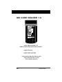
GM CODE READER 1.6
SAVE TIME AND MONEY BY
IDENTIFYING ENGINE PROBLEMS YOURSELF
•
COMPUTER SAFE
•
NO BATTERY REQUIRED
FOR GENERAL MOTORS AND SATURN
VEHICLES FROM 1982 TO 1995
(EXCLUDING CADILLAC)
GM
Innova 1998
Table of Contents
Paragraph
Title
Page No.
YOU CAN DO IT! ........................................................ ii
GENERAL INFORMATION
1.1
1.2
1.3
1.4
1.5
1.6
YOUR VEHICLE'S COMPUTER SYSTEM ...............
ABOUT YOUR CODE READER.................................
TEST CONNECTOR LOCATIONS ............................
SAFETY PRECAUTIONS ...........................................
VEHICLE SERVICE MANUALS ...............................
PRELIMINARY VEHICLE DIAGNOSIS ..................
WORKSHEET
1-1
1-2
1-2
1-3
1-3
1-4
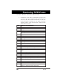
RETRIEVING ECM CODES
2.1
2.2
2.3
2.4
2.5
VEHICLES COVERED ...............................................
BEFORE YOU BEGIN ...............................................
RETRIEVING SERVICE CODES .............................
ERASING SERVICE CODES .....................................
ECM SERVICE CODES ..............................................
2-1
2-2
2-3
2-6
2-6
RETRIEVING ABS CODES
3.1
3.2
3.3
3.4
3.5
ANTI-LOCK BRAKE SYSTEMS ................................
APPLICATIONS .........................................................
RETRIEVING SERVICE CODES .............................
ERASING SERVICE CODES .....................................
ABS SERVICE CODES ...............................................
3-1
3-1
3-2
3-7
3-9
GLOSSARY
4.1
4.2
INTRODUCTION ........................................................ 4-1
GLOSSARY OF TERMS AND ................................... 4-1
ABBREVIATIONS
WARRANTY AND SERVICE
5.1
5.2
i
LIMITED ONE YEAR WARRANTY .......................... 5-1
SERVICE PROCEDURES .......................................... 5-1
GM
1
1
2
3
GM
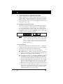
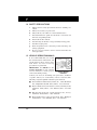
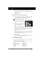
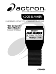
•
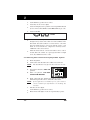
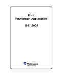
Test connector usually found
under the left side of the
dashboard.
•
Set Selector switch to ECM A-B
position.
•
Make sure ignition is off. Plug
Code Reader into test connector.
•
Turn on ignition. DO NOT
START ENGINE.
•
Read codes from flashing
"Check Engine" or "Service
Engine Soon" light.
Pinpoint Problems
•
Locate fault code(s) in the
appropriate Service Codes List.
po e ha C
l
O
Ig ssi In ft o D
lo ni ble je r C E D
ss tio b ct r
T o n lo or a EF
h hro f 5 sy wn c nk IN
ig
ir s
I
8
T h ttle X ste fu cu ha TIO
23
lo hro du p sig m el it ft s N
w t ri os n fa in is e
n
F d tle ng it a u je
s
l
gr ue ur p e ion or lt cto no or
t
o l i o n
M un cu ng sit gi se 6X In r fu w - ci
n
vo an d to en ion e ns si te se ork r
id or gn rm
ff gi
i
in
T lta fol
re ne sen le (T al it
g
h g d
la id so or P (S ten
p
M ro e i a
y le r de S) at t
ci ix ttle s l ir
(T c - u 7
ci
rc tu p ow te
P ele si rn X
In u re o
rc
m
S r g ) si
i
s o
u
) a n
gn
V tak t p C iti r h per
it
- ti al
si on v
pr eh e A rob on on igh at
ic
gn
u
ol
s
op
l t
re
M obl le ir em rol en
ta
a
e
l
a em sp T s ( so
g
n
(M
M
22
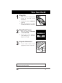
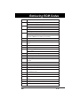
You Can Do It!
Plug It In
Read Fault Codes
CHECK ENGINE
SERVICE
ENGINE
SOON
tri
ev
Read manual for a complete description of the Code Reader and
it's proper use and operation.
ii
1
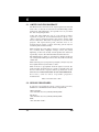
1.1 YOUR VEHICLE'S COMPUTER SYSTEM
Today's vehicles are equipped with computer self-testing
abilities that can locate problems in your vehicle and store
them as service codes in the vehicle's onboard computer. The
Code Reader allows you access to the computer's memory and
recalls the service codes.
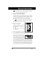
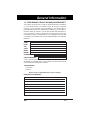
1.1.1 Instrument Panel Indicator Lights
Your vehicle's Instrument panel has several indicator lights, such
as the "Check Engine", "Service Engine Soon", "ABS", "Shift to
D2" and "Temperature" indicator lights. These lights do more
than tell you to check for engine, brake, or other component
malfunctions. They can also transmit the service codes in the
computer memory by blinking on and off.
CHECK ENGINE
NOTE:
SERVICE
ENGINE
SOON
If your instrument panel indicator lights do not come
on when you turn on the ignition, please refer to your
vehicle's service manual. You may have problems in
the car's circuitry. You must fix these problems before
you can obtain service codes from the vehicle's
onboard computer.
1.1.2 Service Codes
The service codes are also called "fault codes", "diagnostic
codes" or "trouble codes". These codes can be used to identify
systems or components which are malfunctioning.
The computer records codes for two types of problems:
1-1
■
"Hard" Codes. "Hard" codes are stored for problems
which are happening now. The instrument panel indicator
light will stay on when the engine is running.
■
"Intermittent" Codes or "Continuous Memory" Codes.
Intermittent service codes are stored in the computer's
memory for problems which occur intermittently, or for
problems which happened in the past but are not currently
present. Intermittent problems may cause the panel
indicator light to flicker or to turn on intermittently.
Intermittent codes are stored in the computer's memory for
a set period of time (usually 50 start cycles). If an
intermittent problem does not recur within this time
period, the computer automatically erases the related
intermittent fault code from it's memory.
GM
General Information
NOTE :
For Saturn vehicles, either the "Shift to D2" light or
the "Temperature" indicator light is used to transmit
Saturn Electronic Transmission codes.
1.2 ABOUT YOUR CODE READER
The Code Reader is a device which connects to your vehicle's
computer self-test connector. It allows the computer to output
the service codes through the vehicle's instrument panel
indicator lights. The Code Reader can be used to retrieve:
■
Engine/Electronic Transmission codes (ECM/PCM)
NOTE:
■
Unless otherwise indicated, any reference to ECM
throughout this manual also applies to PCM.
Anti-Lock Brake System codes (ABS)
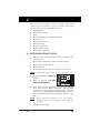
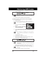
1.2.1 Controls and Indicators
Selector Switch – Selects
operating mode for Code Reader:
■
ECM A-B – Use to retrieve ECM
codes
■
ABS A-H – Use to retrieve ABS
service codes
1.3 TEST CONNECTOR LOCATIONS
•
The gateway to your vehicle's onboard computer.
Your vehicle test connector also
known as the Assembly Line Data
Link (ALDL) connector or Assembly
Line Communication Link (ALCL)
connector is usually black in color
and is most likely found under the left side of the dashboard.
Some connectors can be found on the right kick panel, under
the center of the dashboard, on the side of the fuse block or
under the ashtray in the center console. The connector might
have a plastic cover on it labeled "Diagnostic Connector". If
you have any questions about the connector's location, please
refer to your vehicle's service manual for detailed information.
GM
1-2
1
1.4 SAFETY PRECAUTIONS
•
Always observe safety precautions whenever working on a
vehicle.
a.
b.
c.
Always wear safety eye protection.
Only work on your vehicle in a well-ventilated area.
Put transmission in “park” (for automatic) or “neutral” (for
manual). Set parking brake.
Put blocks on drive wheels.
Avoid moving fan blades or any potentially moving parts.
Avoid hot engine parts.
Turn off ignition before connecting (or disconnecting) any
testing equipment.
Please read your vehicle’s service manual and follow it’s
safety procedure.
d.
e.
f.
g.
h.
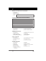
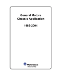
1.5 VEHICLE SERVICE MANUALS
It is recommended that you consult
the manufacturer’s instructions and
specifications in these service manuals before any test or tune-up
procedures are performed.
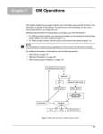
IMPORTANT: You MUST use the
wiring diagrams in your vehicle's
service manual to ensure proper
connections during testing.
PNK-BLK
F8
PNK-BLK
DK GRN-WHT
BLK-WHT
PNK-BLK
GRY
RED
F/P FUSE
6
2
4
1
3
FUEL PUMP
PRIME CONN
FUEL PUMP
TYPICAL WIRING
DIAGRAM
Contact your local car dealership, auto parts store, bookstore
or public library for availability of these manuals. The
following companies publish valuable repair manuals:
1-3
■
General Motors Publications, Helm, Inc., 14310 Hamilton
Ave., Highland Park, MI 48203, Phone: (800) 782-4356
■
Haynes Publications, 861 Lawrence Drive, Newbury Park,
California 91320, Phone: (805) 498-6703, Fax: (805) 4982867
■
Mitchell International, 14145 Danielson St., Poway,
California 92064, Phone: (888) 724-6742
■
Motor Publications, 5600 Crooks Road, Troy, Michigan
48098, Phone: (800) 426-6867, Fax: (313) 828-0215
GM
General Information
1.6 PRELIMINARY VEHICLE DIAGNOSIS WORKSHEET
The purpose of this form is to help you gather preliminary information
on your vehicle before you retrieve codes. By having a complete
account of your vehicle's current problem(s), you will be able to
systematically pinpoint the problem(s) by comparing your answers to
the fault codes you retrieve. You can also provide this information to
your mechanic to assist in diagnosis and help avoid costly and
unnecessary repairs. It is important for you to complete this form to help
you and/or your mechanic have a clear understanding of your vehicle's
problems.
NAME:
DATE:
VIN*:
YEAR:
MAKE:
MODEL:
ENGINE SIZE:
VEHICLE MILEAGE:
*VIN: Vehicle Identification Number, found at the base of the
windshield on a metallic plate, or at the driver door latch area (consult
your vehicle owner's manual for location).
TRANSMISSION:
❑ Automatic
❑ Manual
Please check all applicable items in each category.
DESCRIBE THE PROBLEM:
GM
1-4
1
WHEN DID YOU FIRST NOTICE THE PROBLEM:
❑
❑
❑
❑
Just Started
Started Last Week
Started Last Month
Other:
LIST ANY REPAIRS DONE IN THE PAST SIX MONTHS:
PROBLEMS STARTING
❑ No symptoms
❑ Will not crank
❑ Cranks, but will not start
❑ Starts, but takes a long time
ENGINE QUITS OR STALLS
❑ No symptoms
❑ Right after starting
❑ When shifting into gear
❑ During steady-speed driving
❑
❑
❑
❑
IDLING CONDITIONS
❑ No symptoms
❑ Is too slow at all times
❑ Is too fast
❑ Is sometimes too fast or too slow
❑ Is rough or uneven
❑ Fluctuates up and down
RUNNING CONDITIONS
❑ No symptoms
❑ Runs rough
❑ Lacks power
❑ Bucks and jerks
❑ Poor fuel economy
❑ Hesitates or stumbles on
❑
❑
❑
❑
❑
Right after vehicle comes to a stop
While idling
During acceleration
When parking
Backfires
Misfires or cuts out
Engine knocks, pings or rattles
Surges
Dieseling or run-on
accelerations
1-5
GM
General Information
AUTOMATIC TRANSMISSION PROBLEMS (if applicable)
❑ No symptoms
❑ Vehicle does not move when in
❑ Shifts too early or too late
gear
❑ Changes gear incorrectly
❑ Jerks or bucks
PROBLEM OCCURS
❑ Morning
❑ Afternoon
❑ Anytime
ENGINE TEMPERATURE WHEN PROBLEM OCCURS
❑ Cold
❑ Warm
❑ Hot
DRIVING CONDITIONS WHEN PROBLEM OCCURS
❑ Short - less than 2 miles
❑ With headlights on
❑ 2 ~ 10 miles
❑ During acceleration
❑ Long - more than 10 miles
❑ Mostly driving downhill
❑ Stop and go
❑ Mostly driving uphill
❑ While turning
❑ Mostly driving level
❑ While braking
❑ Mostly driving curvy roads
❑ At gear engagement
❑ Mostly driving rough roads
❑ With A/C operating
DRIVING HABITS
❑ Mostly city driving
❑ Highway
❑ Park vehicle inside
❑ Park vehicle outside
GASOLINE USED
❑ 87 Octane
❑ 89 Octane
❑ Drive less than 10 miles per day
❑ Drive 10 to 50 miles per day
❑ Drive more than 50 miles per day
❑ 91 Octane
❑ More than 91 Octane
WEATHER CONDITIONS WHEN PROBLEM OCCURS
❑ 32 ~ 55° F (0 ~ 13° C)
❑ Above 55° F (13° C)
❑ Below freezing (32° F / 0° C)
CHECK ENGINE LIGHT / DASH WARNING LIGHT
❑ Sometimes ON
❑ Always ON
❑ Never ON
PECULIAR SMELLS
❑ "Hot"
❑ Sulfur ("rotten egg")
❑ Burning rubber
❑ Gasoline
❑ Burning oil
❑ Electrical
STRANGE NOISES
❑ Rattle
❑ Knock
❑ Squeak
❑ Other
GM
1-6
2
2.1 VEHICLES COVERED
This Code Reader may be used to retrieve engine service codes
from most General Motors (GM) and Saturn domestic cars and
trucks (EXCEPT Geo, Nova, and Sprint). Includes all models
EXCEPT Cadillacs and diesel vehicles. Specific makes and
models are listed below.
Model
Year
Make
1982-93 Buick
1994
2-1
Model
Century, Electra, Electra Wagon, Estate
Wagon, Le Sabre, Le Sabre Wagon, Park
Avenue, Reatta*, Regal, Grand National,
Riviera*, Roadmaster, Skyhawk, Skylark,
Somerset
Chevrolet
Berreta, Camaro, Caprice, Cavalier, Celebrity, Chevette, Citation, Corisca, Corvette,
El Camino, Impala, Lumina, Monte Carlo
Oldsmobile
Achieva, Calais, Custom Cruiser, Cutlass
Calais, Ciera, Cutlass Cruiser, Cruiser
Wagon, Cutlass Supreme, Supreme Classic,
Delta 88, Eighty-eight, Firenze, Ninetyeight, Omega, Toronado*, Touring Sedan,
Trofeo*
Pontiac
6000, 6000 STE, Bonneville, Fiero, Firebird,
Grand Am, Grand Prix, J 2000, Lemans,
J Parisienne, Phoenix, Safari, Safari Wagon,
Sunbird, T 1000
Saturn
All models
Trucks
and Vans
All one ton capacity or less with gas
engines
Buick
Roadmaster 5.7 liter
Chevrolet
Camaro 3.4 liter/5.7 liter, Caprice 5.7 liter,
Caprice 5.7 liter, Cavalier 3.1 liter,
Lumina 3.1 liter
Pontiac
Firebird 3.4 liter/5.7 liter, Sunbird 2.0 liter/
3.1 liter
Saturn
All models
Trucks
and Vans
All one ton capacity or less with gas
engines
GM
Retrieving ECM Codes
Model
Year
1995
Make
Model
Chevrolet
Caprice 4.3 liter
Saturn
All models
Trucks
and Vans
All one ton capacity or less with gas
engines (EXCEPT S/T Series vehicles)
* Not applicable to models equipped with climate control
computers
NOTE:
For 1994 and 1995 vehicles, only the models listed
above are compatible with the Code Reader.
The Code Reader is not compatible with 1996 and
later model year vehicles.
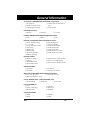
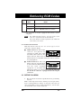
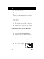
2.1.1 Vehicle Test Connector
GM and Saturn vehicles use one of two types of test
connectors: 12-pin or 16-pin.
■
12-Pin Connector: The 12-pin
connector was phased out
completely in 1996. Some 1994
and 1995 vehicles still use the
12-pin connector, but because of changes in the ECM, the
Code Reader is not compatible with some of these systems
(see paragraph 2.1).
■
16-Pin Connector: The new
16-pin connector was introduced
1 2 3 4 5 6 7 8
on some 1994 and 1995 models,
9 10111213141516
and was made standard
equipment on all 1996 and
subsequent model year vehicles. The Code Reader will
not work on vehicles equipped with the 16-pin
connector.
2.2 BEFORE YOU BEGIN
•
Fix any known mechanical problems before performing
any test.
Make a thorough check before starting any test procedure.
Loose or damaged hoses, wiring, or electrical connectors are
often responsible for poor engine performance, and in some
cases they may cause a “false” fault code.
GM
2-2
2
Please read your vehicle’s service manual for proper
connection of vacuum hoses, electrical wiring, and wiring
harness connectors. Check the following areas:
a.
All fluid levels
b.
Air cleaner and ducts
c.
Belts
d.
Mechanical linkage associated with sensor
e.
Vacuum hoses
f.
Spark plugs and wires
g.
Electrical wiring
h.
i.
j.
Electrical connectors
Proper battery voltage
Fuel system components
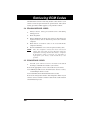
2.3 RETRIEVING SERVICE CODES
•
Always observe safety precautions before and during the
testing process.
•
•
Fix any known mechanical problems before this test.
1.
Turn off ignition.
2.
Connect the Code Reader to the vehicle test connector.
Have pencil and paper handy.
NOTE:
3.
Set Selector Switch to ECM A-B
position.
4.
Turn on ignition. DO NOT
START THE ENGINE.
5.
Read codes from the "Check Engine" or "Service Engine
Soon" light (from the "Shift to D2" light - 1991 and 1992
models or the "Temperature" indicator light - 1993 and
subsequent - for Saturn Electronic Transmission codes) on
your vehicle's instrument panel. Be sure to write the codes
down.
NOTE:
•
2-3
The Code Reader only fits into the connector one way.
If the light does not blink, refer to your vehicle's
service manual for information on checking the
circuitry.
All codes are two digits.
GM
Retrieving ECM Codes
•
Each code is transmitted three times before the next code
is sent.
•
Code sets will begin with Code 12 ("System Pass") even if
fault codes are present.
•
The codes will continue to be sent as long as the ignition is
on and the Code Reader is connected.
•
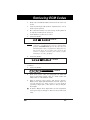
•
Count blinks to get the service codes:
Code 12 looks like:
= Code 12
PAUSE
BLINK
BLINK
Code 12 is not a fault code. Code 12 indicates the
computer's self-diagnostic system is functioning
properly (SYSTEM PASS). If code 12 is the only code
which displays when you perform the diagnostic test,
this means there are no fault codes stored in the
vehicle's computer. Consult your vehicle's repair
manual for "no codes" problems.
NOTE:
•
BLINK
Code 22 looks like:
= Code 22
PAUSE
BLINK
BLINK
BLINK
BLINK
IMPORTANT: Any code that ends in zero ("0") is transmitted
as follows:
•
Code 30 looks like:
ABNORMALLY LONG PAUSE
BLINK
GM
BLINK
= Code 30
BLINK
6.
Next, erase service codes (see paragraph 2.4). This will
help you determine which codes are "hard" faults and
which codes are "intermittent" faults.
7.
Turn on ignition, start engine, and observe "Service
Engine Soon" light; light should turn off. Run engine for
several minutes (to allow engine to reach normal
operating temperature), then observe "Service Engine
Soon" light:
■
If "Service Engine Soon" light turns on, turn off ignition
and repeat steps 2 through 5. This reveals "hard" fault
codes.
2-4
2
NOTE:
■
8.
If "Service Engine Soon" light does not turn on, the initial
stored fault codes were all "intermittent" fault codes.
(Refer to the "Diagnostic Procedures" section in the
manufacturer's service manual for your vehicle.)
Follow the testing and repair procedures outlined in the
manufacturer's service manual for your vehicle to correct
"hard" faults. Codes should be addressed and eliminated
in the order they were received, erasing and retesting
after each repair is made to be sure the fault was
eliminated. Code 12 will appear alone when no other fault
codes are present.
NOTE:
9.
It may be necessary to test drive the vehicle to
reset "hard" fault codes 13, 15, 24, 44, 45, and 55
after they have been erased.
Whenever codes 51, 52, 54, or 55 are displayed with
other codes, troubleshoot and eliminate the "50
Series" codes first, then proceed with the lowernumbered codes.
Turn off ignition and remove the Code Reader.
2.3.1 Servicing Fault Codes
Diagnostic trouble codes indicate a problem in a circuit, not
necessarily a faulty component. DO NOT replace components
based only on trouble codes without first following the service
procedures described in your vehicle's repair manual. Most
faults (including those that set trouble codes) are caused by
damaged, shorted or open wiring, damaged or corroded
connections, improper voltages or grounds, or other
mechanical problems.
Sometimes a fault in one circuit or system will cause the
computer to set a fault code for a different circuit or system.
Example:
A defective spark plug wire can cause a "rich condition" fault
code to be set on the oxygen sensor circuit. In this case,
replacing any component in the oxygen sensor circuit will not
correct the fault, because the problem is caused by the
defective spark plug wire and not by the oxygen sensor circuit.
This is called a "false" code.
For this reason, it is IMPORTANT that you make a thorough
inspection of all systems: wiring, hoses, vacuum, engine
mechanical, charging, ignition, power, ground, fuel, (some of
these systems are not connected to the computer system, but
2-5
GM
Retrieving ECM Codes
will still affect it) before retrieving trouble codes. Refer to your
vehicle's service/repair manual for specifications and system
testing procedures which apply to your particular vehicle.
2.4 ERASING SERVICE CODES
•
Always observe safety precautions before and during
testing process.
1.
Turn off ignition.
2.
Remove ECM fuse from the fuse block or disconnect the
negative battery cable to disconnect power to the vehicle's
computer.
3.
Wait fifteen seconds for codes to be erased from the
computer's memory.
4.
Reconnect ECM fuse or reconnect negative battery cable.
NOTE:
Once the computer's memory has been erased your
vehicle may run rough for up to 40 miles while new
information is being saved in the vehicle's computer.
If the battery cable is removed, you will have to
reprogram your radio, clock and memory seat
position.
2.5 ECM SERVICE CODES
•
Consult your vehicle's service manual for detailed
meanings or definitions related to your vehicle.
Refer to the appropriate service codes table for your vehicle:
2.5.1 GM Engine/Electronic Transmission Service Codes;
Saturn Engine Service Codes
2.5.2 Saturn Electronic Transmission Service Codes
Refer to the "Diagnostic Charts" and "Diagnostic Aids" in your
vehicle's service manual to further assist in the fault isolation
and elimination process.
GM
2-6
2
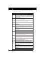
2.5.1 GM Engine/Electronic Transmission Service Codes; Saturn
Engine Service Codes
CODE
SERVICE CODE DEFINITION
11
(Saturn vehicles ONLY): Indicates transmission service
codes will be displayed next on the "Shift to D2" light
(1991-92 models) or "Temperature" indicator light (1993
and later models)
12
Diagnostic mode; no distributor signal to Electronic
Control Module; System PASS
13
Oxygen sensor signal fault - signal too low / open left
oxygen sensor circuit (Dual sensor models)
14
Coolant sensor or circuit fault - signal voltage low or
shorted
15
Coolant temperature sensor or circuit fault - signal
voltage high
16
Battery or alternator problem - voltage too high or low
Direct ignition system (DIS) fault line open or shorted to
ground
Ignition system fault - loss of 2X or Low Resolution
Pulse signal
Transmission speed error
17
RPM signal problem
Camshaft sensor - circuit problems
Electronic Control Module (ECM) computer circuit
problem - Pull-up resistor (Saturn)
18
Camshaft or Crankshaft sensor - circuit problems
Fuel Injector circuit is not working properly - possible
blown fuel injector fuse
19
Ignition system fault - Intermittent 7X signal or loss of
58X signal or 6X signal (Saturn)
21
Throttle position sensor (TPS) - signal voltage is high
22
Throttle position sensor (TPS) - signal voltage is low
Fuel cutoff relay circuit - open or shorted to ground
23
Manifold air temperature (MAT) sensor - signal voltage
is low or high
Throttle position sensor (TPS) error
Mixture Control (M/C) solenoid - open or short circuit
problems
Intake Air Temperature Sensor (IAT) low
2-7
GM
Retrieving ECM Codes
CODE
SERVICE CODE DEFINITION
24
Vehicle speed sensor (VSS) - open or short circuit
problems or park/neutral switch circuit problem
25
Manifold air temperature (MAT) sensor - signal voltage
is low or high
Vacuum switching valve circuit open or shorted to
ground
ATS sensor - signal voltage is high or low
26
Quad-Driver module or Quad-driver No. 1 error
27
2nd gear switch problem
Quad-Driver module or Quad-driver No. 2 error
28
3rd gear switch
Quad-Driver module or Quad-driver No. 3 error
(Corvette)
(Transmission) Fluid pressure switch assembly - open or
short circuit problems
29
4th gear switch
Quad-Driver module or Quad-driver No. 3 error
Secondary air injection system - circuit problems
31
Manifold absolute pressure (MAP) sensor - signal
voltage is low
Fuel injector
Park/Neutral switch - circuit problems
CAM sensor - circuit problems
Engine speed control governor malfunction (Van)
Turbocharger wastegate overboost
Wastegate electrical signal - open or shorted to ground
Purge solenoid voltage high (carburetor engines)
32
Barometric pressure (BARO) sensor circuit failure
Exhaust gas recirculation (EGR) valve diagnostic switch closed during engine start-up or open when EGR flow
requested by ECM
Electronic vacuum regulator valve (EVRV) error (EVRV
controls EGR vacuum)
GM
2-8
2
CODE
SERVICE CODE DEFINITION
33
Mass air flow (MAF) sensor - signal voltage or frequency
is high during engine idle
Manifold absolute pressure (MAP) sensor - signal
voltage is high during engine idle (Note: Engine misfire
or unstable idle may cause this code)
34
Mass air flow (MAF) sensor - signal voltage or frequency
is low during engine cruise
Manifold absolute pressure (MAP) sensor - signal
voltage is low during ignition on
Pressure sensor circuit - signal voltage too high or low
(carburetor engines)
35
Idle air control (IAC) system problem - can not set
desired RPM or idle speed actuator (ISA) carbureted
system problems
36
Mass air flow (MAF) sensor - burn-off circuit problem
Transmission shift problem (electronically controlled
transmissions only)
Direct ignition system (DIS) fault - loss of 24X signal or
extra or missing pulses in electronic spark timing (EST)
signal
Ignition system fault - loss of High Resolution Pulse
signal
37
Brake switch stuck"on"
38
Brake switch circuit fault
Knock sensor (KS) - open circuit problem
39
Torque converter clutch (TCC circuit fault)
Clutch switch circuit problems
Knock sensor (KS) - short circuit problem
41
Cam sensor (CAM) failure
Cylinder select error
Tach input error - no reference pulses during engine run
Electronic spark timing (EST) circuit - open or shorted
to ground during engine run
Direct ignition system (DIS) fault - bypass circuit open
or shorted to ground during engine run
Ignition system fault - loss of 1X Reference Pulse signal
2-9
GM
Retrieving ECM Codes
CODE
SERVICE CODE DEFINITION
42
Electronic spark timing (EST) circuit - open or shorted
Direct ignition system (DIS) fault - bypass circuit open
or shorted to ground during engine run
Fuel cutoff relay circuit - open or shorted to ground
43
Electronic spark timing (EST) circuit - low voltage
detected
Electronic spark control (ESC) - circuit problems
44
Lean exhaust indicated (Left side on dual oxygen models)
45
Rich exhaust indicated (Left side on dual oxygen
models)
46
Vehicle anti-theft system (VATS) failure
Power steering pressure switch failure
47
Circuit or component problem in ECM/PCM (communication error)
Knock sensor module error (inside computer)
48
Misfire symptom
Mass air flow (MAF) sensor - circuit error
49
RPM is high at idle (possible vacuum leak)
50
System voltage is low
51
Computer problem; faulty, wrong or incorrectly installed
PROM circuit; or ECM/PCM failure
52
Calibration Package Chip or ECM fault or oil temperature sensor fault/low engine temperature
(Corvette); faulty or missing PROM/Calibration Package
Chip; ECM problem
System voltage high for a long period of time
53
System voltage too high (over 17.7 volts to ECM) or
EGR system fault or alternator voltage not normal or
Vehicle Anti-Theft System fault
54
Fuel pump circuit fault or Mixture Control (M/C)
solenoid fault or Electronic Control Module (ECM)
fault/EGR solenoid #2 failure (3.8L VIN1)
Fuel pump relay
55
GM
Electronic Control Module (ECM) fault or oxygen sensor
circuit fault or EGR solenoid #3 failure (3.8L VIN1) or
fuel lean monitor (Corvette)
2-10
2
CODE
SERVICE CODE DEFINITION
56
Vacuum sensor circuit fault or quad driver "B" fault
(3.8L VIN1)
Corrosivity/add coolant
57
Boost control problem (3.8L VIN1)
58
Vehicle Anti-Theft System fault (3.8L)
Transmission Temperature Sensor (TTS) - short circuit
Transmission fluid temp high
59
Transmission Temp Sensor (TTS) - open
Transmission fluid temp low
60
Transmission not in drive
61
Oxygen sensor signal fault or port throttle system fault
or on-board cruise control fault (vent solenoid circuit)
Air Conditioner (A/C) system performance problems
62
Engine oil temperature sensor fault or gear switch
signal circuit fault or on-board cruise control fault
(vacuum solenoid circuit)
63
EGR flow problem or on-board cruise control problem
Servo Position Sensor (SPS) circuit fault or Manifold
Absolute Pressure (MAP) sensor fault or oxygen sensor
fault
64
EGR flow problem or on-board cruise control problem or
Manifold Absolute Pressure (MAP) sensor fault or
oxygen sensor fault
65
EGR flow problem or on-board cruise control problem
Servo Position Sensor (SPS) circuit fault or Manifold
Absolute Pressure (MAP) sensor fault or oxygen sensor
fault or fuel injector current low
66
Electronic Control Module (ECM) computer circuit fault
or air conditioning pressure sensor circuit fault or low
air conditioning refrigerant charge
(Transmission) 3-2 shift control solenoid - circuit
problems
67
Cruise control - switch circuit problems
Air Conditioner (A/C) pressure sensor - circuit problems
Torque Converter Clutch (TCC) solenoid - circuit
problems
Cruise control switches - circuit problems
2-11
GM
Retrieving ECM Codes
CODE
SERVICE CODE DEFINITION
68
On-board cruise control switch circuit problems Servo
Position Sensor (SPS) circuit fault or shorted A/C clutch
relay circuit (Corvette) or overdrive ratio error
69
Air conditioning head pressure switch circuit fault or air
conditioning pressure switch problem
Torque converter clutch stuck "on"
70
Air conditioning refrigerant pressure sensor circuit fault
(high pressure) or quad driver module error
71
Air conditioning evaporator temperature sensor circuit
fault (low temp.)
72
Gear select switch circuit fault - Corvette only
Vehicle Speed Sensor (VSS) - loss of signal
73
Air conditioning evaporator temperature sensor circuit
fault (high temp.)
(Transmission) Pressure control solenoid - circuit
problems
74
Traction control circuit voltage low
75
Digital EGR fault - #1 solenoid or system voltage low
(charging system problem)
Transmission voltage low
76
Digital EGR fault - #2 solenoid
77
Digital EGR fault - #3 solenoid
Primary cooling fan relay driver circuit - circuit
problems
78
Secondary cooling fan relay driver circuit - circuit
problems
79
Vehicle Speed Sensor (VSS) - signal voltage too high
Transmission Temperature Sensor (TTS) - high
temperature
80
Vehicle Speed Sensor (VSS) - signal voltage too low;
transmission component fault
81
QDM Solenoid "B" monitored voltage differs from
commanded
Anti-Lock Brake System (ABS) message fault (Saturn)
Brake switch circuit problems
GM
2-12
2
CODE
SERVICE CODE DEFINITION
82
Internal PCM communication fault (Saturn) or QDM
Solenoid "A" monitored voltage differs from commanded
Ignition system fault - 3X signal problem
83
Torque Converter Clutch (TCC) solenoid - circuit
problems
Reverse Inhibit - open or short circuit in reverse inhibit
solenoid
84
3-2 Control solenoid - open or short circuit problems
Skip shift solenoid - open or short circuit problems
85
Programmable Read Only Memory error or undefined
gear ratio (input or output sensor failure)
Torque converter clutch (TCC) - TCC is mechanically
stuck on
86
Analogue/Digital Electronic Control Module (ECM)
error or shift Solenoid "B" stuck on
87
Electrically Erasable Programmable Read Only Memory
(EEPROM) error or shift Solenoid "B" stuck off or high
gear ratio error
88
Electronic Control Module (ECM) computer circuit fault
89
Power Management fault
90
TCC error
91
Skip shift light - open or short circuit problems in skip
shift light circuit
93
Pressure control solenoid - transmission line pressure
not at desired level
95
Change oil light - wrong voltage is present in light
circuit for more than 26 seconds
96
Transmission voltage low - low system voltage possibly
caused by generator voltage supply circuit or power
train control module
Low oil light - wrong voltage is present in light circuit
for more than 26 seconds
97
Vehicle speed sensor (VSS) - output circuit problems
99
Tachometer output circuit problems
2-13
GM
Retrieving ECM Codes
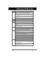
2.5.2 Saturn Electronic Transmission Service Codes
•
Transmission codes will be transmitted (if present) after
all engine codes are transmitted and code 11 has been
sent. Code 11 indicates that transmission codes are
present and will be transmitted on the "Shift to D2" light
(1991-92 models) or the "Temperature" indicator light
(1993 and later models).
CODE
SERVICE CODE DEFINITION
13
Line pressure high
14
Line pressure low
15
Hot light
16
No 1st gear
Electrical variable orifice (EVO) fault
17, 18
No gears available
21
2nd gear stuck "on"
22
No 2nd gear
23
No 3rd gear
24
No 4th gear
25
No torque converter clutch
26
Torque converter clutch stuck "on"
27
Quick quad-driver output fault
31
Transaxle temperature circuit open
32
Transaxle temperature circuit grounded
34
Powertrain Control Module (PCM) - communication
failure
35
No turbine speed signal
36
Turbine speed signal noise
41
Vehicle Speed Sensor (VSS) circuit - no signal
42
Vehicle Speed Sensor (VSS) circuit - signal noise
43
Master relay - open or grounded
44
Master relay - shorted
45
Gear selector switch circuit problem - no signal
46
Gear selector switch circuit problem - invalid signal
47
Powertrain Control Module (PCM) computer circuit
problem - communication interrupt failure
GM
2-14
2
CODE
SERVICE CODE DEFINITION
48
Hold mode voltage is too low
Reference input intermittent
49
Gear selector error signal
51
Powertrain Control Module (PCM) computer circuit
problem
52
Hold mode stuck "on"
Battery voltage out of range
53
Hold mode stuck "off"
ESC (Knock present)
54
Powertrain Control Module (PCM) computer circuit
problem
5-volt reference ground
55
Transaxle temperature sensor failure
56
Generic Field-Effect Transistor (FET) driver failure
57
Powertrain Control Module (PCM)
58
Battery voltage unstable
61
Possible open or intermittent in DIS module harness 6X
Signal fault
Powertrain Control Module (PCM)
62
Powertrain Control Module (PCM)
63
Powertrain Control Module (PCM)
Option check sum error (set if tire size and options do
not compare with those stored)
64
Powertrain Control Module (PCM)
65
Ignition voltage problem
66
Clamp shorted
67
Clamp open
Handwheel sensor circuit fault
68
Line circuit grounded or open
69
Line circuit shorted
71
2nd line circuit - grounded or open
Cooling system high temperature
72
2nd line circuit - shorted
Cooling system low temperature
2-15
GM
Retrieving ECM Codes
CODE
SERVICE CODE DEFINITION
73
3rd line circuit - grounded or open
Coolant sensor signal unstable
74
Coolant/Transmission temperature sensor ratio error
3rd line circuit - shorted
75
3rd gear stuck "on"
Air temperature sensor signal
76
4th line circuit - grounded or open
Throttle position sensor (TPS) to manifold absolute
pressure (MAP) sensor voltage out of range
77
4th line circuit - shorted
78
4th gear stuck "on"
79
Torque Converter Clutch (TCC) circuit - grounded or
open
81
Torque Converter Clutch (TCC) circuit - shorted
82
Transaxle temperature unstable
83
Transaxle temperature low
Low coolant
84
Brake switch stuck open
85
Brake switch stuck closed
86
Engine speed invalid
87
Torque Converter Clutch (TCC) hold circuit - grounded
or open
88
Torque Converter Clutch (TCC) hold circuit - shorted
89
Master relay stuck "on"
91
Assembly Line Diagnostic Link (ALDL)
92
Clamp circuit - intermittent fault
93
Torque Converter Clutch (TCC) hold circuit intermittent fault
94
Master enable relay circuit intermittent fault
95
Line circuit - intermittent fault
96
Torque Converter Clutch (TCC) circuit - intermittent
fault
97
2nd gear circuit - intermittent fault
98
3rd gear circuit - intermittent fault
99
4th gear circuit - intermittent fault
GM
2-16
3
3.1 ANTILOCK BRAKE SYSTEMS (ABS)
3.1.1 What is ABS?
The ABS system utilizes several mechanical, hydraulic, and
electric/electronic components to automatically control
hydraulic brake pressure to the rear, or front and rear wheels
(depending on the brake system) to prevent wheel lock-up
during hard braking.
3.1.2 What are the benefits of ABS?
By preventing wheel lock-up during hard braking, ABS helps
maintain vehicle directional stability, as well as driver control,
ensuring a safer and more controlled stop in the shortest
distance.
3.1.3 How does the ABS system work?
The ABS system utilizes a computer called an Electronic
Brake Control Module (EBCM). The system also employs
several sensors and switches which monitor and control wheel
speed and hydraulic brake pressure when hard braking is
applied. When the wheel speed sensor(s) detect a potential
lock-up condition, a signal is sent to the EBCM. The EBCM, in
turn, sends a signal to the hydraulic system to relieve brake
pressure at the affected wheels, preventing the lock-up
condition.
3.1.4 What is the purpose of the Code Reader?
Most ABS systems generate diagnostic service codes when a
fault in the system is detected. These service codes are stored
in the EBCM. The Code Reader allows you to access the
EBCM's memory and recalls the service codes. The EBCM
outputs the service codes through the "Anti-Lock" light on the
vehicle's instrument panel.
3.2 APPLICATIONS
GM vehicles use a variety of Anti-Lock Brake Systems. This
Code Reader may be used to retrieve ABS service codes from
the following vehicle models:
3-1
GM
Retrieving ABS Codes
Year
Model
ABS Type
1989-93 Astro, "G" Series Van, "R" and "V" Series Kelsey-Hayes
Trucks, Safari, Suburban
RWAL
1987-94 Blazer, "C" and "K" Series Pickup, Sierra, Kelsey-Hayes
"S" and "T" Series Pickup (EXCEPT
RWAL
93-94 4.3L M/T)
1989-90 Eldorado, Reatta, Riviera, Seville, ToroTeves II
nado, Delta 88, Bonneville, DeVille,
Electra, Le Sabre, Ninety-Eight, Fleetwood, Park Avenue, Touring Sedan
(EXCEPT 1988 Eldorado, Reatta, Riviera,
Seville, Toronado)
1990-91 Corvette
Bosch 2S
1990-92 Brougham
Bosch 2U
1990-94 Astro, Bravada, Jimmy, Safari, Sierra,
Sonoma, Suburban, Cyclone, Typhoon,
Yukon, "C" and "K" Series Blazer and
Pickup, "S" and "T" Series Blazer and
Pickup, "G" Series Van
Kelsey-Hayes
4WAL
1995
Kelsey-Hayes
4WAL
Astro, "C" and "K" Series Pickup, "G"
Series Van, Safari, Sierra, Suburban,
Tahoe, Yukon
1991-92 Custom Cruiser, Eldorado, Seville,
Reatta, Toronado, Trofeo
Bosch 2U
1991-93 Riviera, Roadmaster, Caprice
Bosch 2U
1993
Bosch 2U
ABS/TCS
Eldorado, Seville
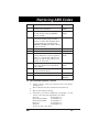
3.3 RETRIEVING SERVICE CODES
•
Always observe safety precautions before and during
testing process.
•
•
Fix any known mechanical problems before this test.
1.
Determine your vehicle's ABS Type (paragraph 3.1) and
retrieve codes using the appropriate procedures:
Have pencil and paper handy.
Teves II
Paragraph 3.3.1
Kelsey-Hayes RWAL
Paragraph 3.3.2
Kelsey-Hayes 4WAL
Paragraph 3.3.3
Bosch 2S
Paragraph 3.3.4
Bosch 2U
Paragraph 3.3.4
Be sure to write codes down.
GM
3-2
3
2.
After retrieving ABS fault codes, erase codes using the
appropriate procedures for your vehicle and ABS system
(paragraph 3.4).
3.
Repeat the procedure to retrieve ABS fault codes (step 1,
above).
NOTE:
It may be necessary to perform a thorough test drive
to reset some fault codes.
4.
In most cases, codes which reappear indicate "hard"
faults. Codes which DO NOT reappear are usually
"intermittent" faults.
5.
Follow the testing and repair procedures outlined in the
manufacturer's service manual for your vehicle to correct
"hard" faults. Codes should be addressed and eliminated
in the order they were received, erasing and retesting
after each repair is made to be sure the fault was
eliminated.
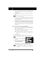
3.3.1 Retrieving Service Codes for Teves II Systems
1.
Turn on ignition. DO NOT START THE ENGINE.
Observe "Anti-Lock" light:
■
If "Anti-Lock" light turns off within 30 seconds, no
ABS service codes have been stored.
■
2.
If "Anti-Lock" light remains on longer than 30
seconds, continue to step 2 to retrieve ABS service
codes.
Turn off ignition.
3.
Connect the Code Reader to the vehicle test connector.
NOTE:
4.
Set Selector Switch to ABS A-H
position.
5.
Turn on ignition. DO NOT
START THE ENGINE.
6.
Read codes from the "Anti-Lock"light on your vehicle's
instrument panel. Be sure to write the codes down.
NOTE:
3-3
The Code Reader only fits into the connector one way.
If the light does not blink, refer to your vehicle's
service manual for information on checking the
circuitry.
GM
Retrieving ABS Codes
•
•
•
All codes are two digits.
•
Second digit of service code is followed by a termination
code ("Anti-Lock" light remains steady on).
Count blinks to get the service codes:
First and second digits of code are separated by a 3 second
pause.
NOTE:
•
DO NOT count termination code as part of second
digit.
Code 13 looks like:
PAUSE
BLINK
7.
BLINK
= Code 13
BLINK TERMINATION
CODE
Up to seven codes can be stored by the EBCM. To check
for additional codes: with ignition still on, disconnect and
then reconnect Code Reader. Repeat this procedure until
all codes have been retrieved.
NOTE:
8.
STEADY ON
BLINK
Service codes cannot be erased until all stored service
codes have been retrieved.
Turn off ignition and remove the Code Reader.
3.3.2 Retrieving Service Codes for Kelsey-Hayes RWAL Systems
1.
Turn off ignition.
2.
Connect the Code Reader to the vehicle test connector.
NOTE:
3.
Set Selector Switch to ABS A-H
position.
4.
Turn on ignition. DO NOT
START THE ENGINE.
NOTE:
5.
There is a 20 second pause before service codes begin
to display.
Read codes from the "Brake" light on your vehicle's
instrument panel. Be sure to write the codes down.
NOTE:
GM
The Code Reader only fits into the connector one way.
If the light does not blink, refer to your vehicle's
service manual for information on checking the
circuitry.
3-4
3
•
•
•
Count blinks to get the service codes.
•
Code 3 looks like:
Codes may be one or two digits.
Codes are displayed as a pattern of one long blink followed
by one or more short blinks. Count ALL blinks to get code.
= Code 3
LONG
BLINK
SHORT
BLINK
SHORT
BLINK
•
The EBCM stores only one service code at a a time, even
though it may detect more than one fault condition. The
first fault detected results in a stored service code. The
detected fault must be corrected, and the service code
must be erased from the computer's memory before
additional codes can be stored.
•
After the first fault is corrected and the service code is
erased, drive the vehicle at a speed greater than 35 mph
to set any additional service codes.
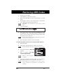
3.3.3 Retrieving Service Codes for Kelsey-Hayes 4WAL Systems
1.
Turn off ignition.
2.
Connect the Code Reader to the vehicle test connector.
NOTE:
3.
Set Selector Switch to ABS A-H
position.
4.
Turn on ignition. DO NOT
START THE ENGINE.
5.
Read codes from the "Anti-Lock" light on your vehicle's
instrument panel. Be sure to write the codes down.
NOTE:
•
•
•
3-5
The Code Reader only fits into the connector one way.
If the light does not blink, refer to your vehicle's
service manual for information on checking the
circuitry.
All codes are two digits.
Count blinks to get the service codes:
First and second digits of code are separated by a pause.
GM
Retrieving ABS Codes
•
Code 21 looks like:
= Code 21
PAUSE
BLINK
NOTE:
6.
BLINK
BLINK
Service codes will repeat as long as Code Reader is
connected.
Turn off ignition and remove the Code Reader.
3.3.4 Retrieving Service Codes for Bosch 2S and 2U Systems
1.
Turn off ignition.
2.
Connect the Code Reader to the vehicle test connector.
NOTE:
The Code Reader only fits into the connector one way.
3.
Set Selector Switch to ABS A-H
position.
4.
Turn on ignition. DO NOT
START THE ENGINE.
5.
Read codes from the "Service ABS" or "Anti-Lock" light on
your vehicle's instrument panel. Be sure to write the codes
down.
NOTE:
•
•
•
•
If the light does not blink, refer to your vehicle's
service manual for information on checking the
circuitry.
All codes are two digits.
Count blinks to get the service codes:
First and second digits of code are separated by a pause.
Code sequence will start with Code 12:
= Code 12
PAUSE
BLINK
NOTE:
•
GM
BLINK
Code 12 is not a fault code. Code 12 indicates the
self-diagnostic system is functioning properly
(system pass).
Each code is repeated three times. After all codes have
been displayed, the entire code sequence is repeated.
NOTE:
6.
BLINK
Service codes will repeat as long as Code Reader is
connected.
Turn off ignition and remove the Code Reader.
3-6
3
3.4 ERASING SERVICE CODES
•
Always observe safety precautions before and during
testing process.
•
Erase codes only when all repairs have been completed.
Determine your vehicle's ABS Type (paragraph 3.2) and erase
codes using the appropriate procedures:
3.4.1
3.4.2
3.4.3
3.4.4
3.4.5
Teves II
Kelsey-Hayes RWAL
Kelsey-Hayes 4WAL
Bosch 2S
Bosch 2U
3.4.1 Erasing Service Codes for Teves II Systems
1.
Drive vehicle at a speed greater than 20 MPH. Service
codes will automatically be cleared.
2.
Repeat procedure for retrieving service codes (paragraph
3.3.1) to make sure codes have been erased and no new
codes have been recorded.
3.4.2 Erasing Service Codes for Kelsey-Hayes RWAL Systems
A.
B.
3-7
For all vehicle models EXCEPT "C" and "K" 3500 Series
Heavy Duty (HD) (1992-93):
1.
Turn off ignition.
2.
Remove STOP/HAZARD fuse from fuse block.
3.
Wait 20 seconds, then reinstall STOP/HAZARD fuse.
4.
Repeat steps 2 and 3 for each code stored. For example: if
four codes were retrieved, remove and install
STOP/HAZARD fuse four times.
5.
Repeat procedure for retrieving service codes (paragraph
3.3.2) to make sure codes have been erased.
For "C" and "K" 3500 Series Heavy Duty (HD) (1992-93)
vehicles ONLY:
1.
Turn off ignition.
2.
Remove STOP/HAZARD fuse from fuse block.
3.
Turn on ignition and observe
"Brake" light. If "Brake" light is
on, a code(s) is stored.
4.
Set Selector Switch to ABS A-H
position.
GM
Retrieving ABS Codes
5.
Connect the Code Reader to the vehicle test connector for
one second, remove the Code Reader for one second,
reconnect the Code Reader for one second, then remove
the Code Reader.
6.
Turn off ignition.
7.
Reinstall STOP/HAZARD fuse in fuse block.
8.
Repeat procedure for retrieving service codes (paragraph
3.3.2) to make sure codes have been erased.
3.4.3 Erasing Service Codes for Kelsey-Hayes 4WAL Systems
1.
Turn on ignition.
2.
Set Selector Switch to ABS A-H
position.
3.
Connect the Code Reader to the vehicle test connector for
two seconds, remove the Code Reader for one second,
reconnect the Code Reader for two seconds, then remove
the Code Reader.
4.
The "Anti-Lock" and "Brake" light should BOTH light,
then turn off. This indicates service codes have been
erased.
5.
Turn off ignition.
6.
Repeat procedure for retrieving service codes (paragraph
3.3.3) to make sure codes have been erased.
3.4.4 Erasing Service Codes for Bosch 2S Systems
GM
1.
Turn off ignition.
2.
Set Selector Switch to ABS A-H
position.
3.
Connect the Code Reader to the
vehicle test connector.
4.
Turn on ignition. "Service ABS" light will begin displaying
service codes.
5.
Remove the Code Reader for one second, then reconnect
the Code Reader for at least one second.
6.
Repeat step 5 three more times (a total of four times)
within a ten second period. LEAVE THE CODE
READER CONNECTED AFTER THE FOURTH
TIME.
3-8
3
7.
The ""Service ABS" light should display code 12
continuously. If any other codes are displayed, repeat
steps 1 through 6.
8.
Turn off ignition.
3.4.5 Erasing Service Codes for Bosch 2U Systems
1.
Turn on ignition and observe "Anti-Lock" light. "AntiLock" light should turn off within 3 to 4 seconds. If "AntiLock" light remains on, a fault is still present.
NOTE:
Service codes cannot be erased until all stored service
codes have been retrieved.
2.
Set Selector Switch to ABS A-H
position.
3.
Connect the Code Reader to the
vehicle test connector and
observe "Anti-Lock" light.
4.
When "Anti-Lock" light turns on, disconnect Code Reader.
5.
When "Anti-Lock" light turns off, reconnect Code Reader
and observe "Anti-Lock" light. When "Anti-Lock" light
turns on, disconnect Code Reader.
6.
Repeat step 5.
7.
When "Anti-Lock" light turns off, reconnect Code Reader.
"Anti-Lock" light will turn on. Disconnect Code Reader.
All service codes are now cleared.
8.
Turn off ignition.
9.
Repeat procedure for retrieving service codes (paragraph
3.3.4) to make sure codes have been erased.
3.5 ABS SERVICE CODES
•
Consult your vehicle's service manual for detailed
meaning related to your vehicle.
Determine your vehicle's ABS Type (paragraph 3.2) and refer
to the appropriate service codes table:
Teves II
Kelsey-Hayes RWAL
Kelsey-Hayes 4WAL
Bosch 2S
Bosch 2U
3-9
Paragraph 3.5.1
Paragraph 3.5.2
Paragraph 3.5.3
Paragraph 3.5.4
Paragraph 3.5.5
GM
Retrieving ABS Codes
3.5.1 Teves II System Service Codes
Code
Service Code Definition
11
Electronic Brake Control Module (EBCM) fault
12
Electronic Brake Control Module (EBCM) fault
21
Main valve fault
22
Left front inlet valve fault
23
Left front outlet valve fault
24
Right front inlet valve
25
Right front outlet valve
26
Rear inlet valve
27
Rear outlet valve
31
Left front Wheel Speed Sensor (WSS)
32
Right front Wheel Speed Sensor
33
Right rear Wheel Speed Sensor
34
Left rear Wheel Speed Sensor
35
Left front Wheel Speed Sensor
36
Right front Wheel Speed Sensor
37
Right rear Wheel Speed Sensor
38
Left rear Wheel Speed Sensor
41
Left front Wheel Speed Sensor
42
Right front Wheel Speed Sensor
43
Right rear Wheel Speed Sensor
44
Left rear Wheel Speed Sensor
45
Left front sensors (2)
46
Right front sensors (2)
47
Rear sensors (2)
48
sensors (3)
51
Left front outlet valve
52
Right front outlet valve
53
Rear outlet valve
54
Rear outlet valve
55
Left front Wheel Speed Sensor
56
Right front Wheel Speed Sensor
57
Right rear Wheel Speed Sensor
58
Left rear Wheel Speed Sensor
GM
3-10
3
Code
Service Code Definition
61
Electronic Brake Control Module loop circuit
71
Left front outlet valve
72
Right front outlet valve
73
Rear outlet valve
74
Rear outlet valve
75
Left front Wheel Speed Sensor
76
Right front Wheel Speed Sensor
77
Right rear Wheel Speed Sensor
78
Left rear Wheel Speed Sensor
3.5.2 Kelsey-Hayes RWAL System Service Codes
Code
Service Code Definition
1
Rear Wheel Anti-Lock (RWAL) Electronic Control Unit
(ECU) malfunction or improper voltage
2
Open isolation valve or faulty ECU
3
Open dump valve or faulty ECU
4
Grounded anti-lock valve reset switch circuit
5
Excessive actuation of the dump valve during an anti-lock
stop
6
Erratic speed signal
7
Shorted isolation valve circuit or faulty ECU
8
Shorted dump valve circuit or faulty ECU
9
Open or grounded circuit to the vehicle speed sensor
10
Brake lamp switch circuit fault
11
Rear Wheel Anti-Lock (RWAL) Electronic Control Unit
(ECU) malfunction or improper voltage
12
Rear Wheel Anti-Lock (RWAL) Electronic Control Unit
(ECU) malfunction or improper voltage
13
Rear Wheel Anti-Lock (RWAL) Electronic Control Unit
(ECU) malfunction
14
Rear Wheel Anti-Lock (RWAL) Electronic Control Unit
(ECU) malfunction
15
Rear Wheel Anti-Lock (RWAL) Electronic Control Unit
(ECU) malfunction
3-11
GM
Retrieving ABS Codes
3.5.3 Kelsey-Hayes 4WAL System Service Codes
Code
Service Code Definition
12
System Normal
13
System Normal (2WD)
14
System Normal (4WD/AWD)
15
System Normal (4WD/AWD)
21
Right front wheel sensor fault
22
Missing right front wheel sensor signal
23
Erratic right front speed sensor
25
Left front speed sensor fault
26
Missing left front speed signal
27
Erratic left front speed sensor
28
Simultaneous loss of both front sensor signals
29
Simultaneous drop out of all 4 sensors
31
Right rear speed sensor fault
32
Missing right rear speed signal
33
Erratic right rear speed sensor
35
Left rear speed sensor fault or VSS circuit open (1993)
36
Missing left rear speed signal or VSS signal missing (1993)
37
Erratic left rear speed signal or erratic VSS signal (1993)
38
Wheel speed error
41
4 Wheel Anti-Lock (4WAL) control unit fault
42
4 Wheel Anti-Lock (4WAL) control unit fault
43
4 Wheel Anti-Lock (4WAL) control unit fault
44
4 Wheel Anti-Lock (4WAL) control unit fault
45
4 Wheel Anti-Lock (4WAL) control unit fault
46
4 Wheel Anti-Lock (4WAL) control unit fault
47
4 Wheel Anti-Lock (4WAL) control unit fault
48
4 Wheel Anti-Lock (4WAL) control unit fault
49
4 Wheel Anti-Lock (4WAL) control unit fault
50
4 Wheel Anti-Lock (4WAL) control unit fault
51
4 Wheel Anti-Lock (4WAL) control unit fault
52
4 Wheel Anti-Lock (4WAL) control unit fault
53
4 Wheel Anti-Lock (4WAL) control unit fault
54
4 Wheel Anti-Lock (4WAL) control unit fault
GM
3-12
3
Code
Service Code Definition
55
4 Wheel Anti-Lock (4WAL) control unit fault
56
4 Wheel Anti-Lock (4WAL) control unit fault
57
4 Wheel Anti-Lock (4WAL) control unit fault
58
4 Wheel Anti-Lock (4WAL) control unit fault
59
4 Wheel Anti-Lock (4WAL) control unit fault
60
4 Wheel Anti-Lock (4WAL) control unit fault
61
4 Wheel Anti-Lock (4WAL) control unit fault
62
4 Wheel Anti-Lock (4WAL) control unit fault
63
4 Wheel Anti-Lock (4WAL) control unit fault
64
4 Wheel Anti-Lock (4WAL) control unit fault
65
4 Wheel Anti-Lock (4WAL) control unit fault
66
4 Wheel Anti-Lock (4WAL) control unit fault
67
Open motor circuit or shorted ECU output
68
Locked motor or shorted motor circuit
71
4 Wheel Anti-Lock (4WAL) control unit fault
72
4 Wheel Anti-Lock (4WAL) control unit fault
73
4 Wheel Anti-Lock (4WAL) control unit fault
74
4 Wheel Anti-Lock (4WAL) control unit fault
81
Brake switch circuit shorted or open
85
Open anti-lock warning lamp
86
Shorted anti-lock warning lamp
88
Shorted brake warning lamp
3.5.4 Bosch 2S System Service Codes
Code
Service Code Definition
12
Diagnostic system operational
21
Right front speed sensor fault
22
Right front toothed wheel frequency error
25
Left front speed sensor fault
26
Left front toothed wheel frequency error
31
Right rear speed sensor fault
32
Right rear toothed wheel frequency error
35
Left rear speed sensor fault
36
Left rear toothed wheel frequency error
3-13
GM
Retrieving ABS Codes
Code
Service Code Definition
41
Right front solenoid valve fault
45
Left front solenoid valve fault
55
Rear solenoid valve fault
61
Pump motor or motor relay fault
63
Solenoid valve relay fault
71
Electronic Brake Control Module (EBCM) fault
72
Serial data link fault
75
Lateral accelerometer fault; short to battery, ground or
open circuit
76
Lateral accelerometer fault, signal out of range or incorrect
3.5.5 Bosch 2U System Service Codes
Code
Service Code Definition
12
Normal
21
Right front wheel sensor fault
22
Right front toothed wheel frequency error
25
Left front wheel sensor fault
26
Left front toothed wheel frequency error
35
Rear axle speed sensor fault
36
Rear axle toothed wheel frequency error
41
Right front solenoid valve fault
45
Left front solenoid valve fault
55
Rear wheels solenoid valve fault
61
Pump motor or motor relay fault
63
Solenoid valve relay fault
71
Electronic brake control module fault
72
Serial data line fault
GM
3-14
4
4.1 INTRODUCTION
The Society of Automotive Engineers has issued a Standard
(SAE J1930) for Electrical/Electronic Systems Diagnostic
Terms, Definitions, Abbreviations, and Acronyms. However, at
the present time, this Standard is not in wide use by vehicle
manufacturers.
This Glossary contains definitions for abbreviations and terms
you may find in this manual or in your vehicle service manual.
These definitions may not agree with those contained in SAE
J1930.
4.2 GLOSSARY OF TERMS AND ABBREVIATIONS
A/C – Air Conditioning.
AAC – Auxiliary Air Control Valve.
ABS – Anti-Lock Brake System.
ACC – Air Conditioning Clutch compressor signal input to
computer relating status of air conditioning clutch.
ACCS – Air Conditioning Cycling Switch.
ACD – Air Conditioner Demand switch.
ACT – Air Charge Temperature sensor or signal circuit.
ACV – Thermactor Air Control Valve.
AIR – Air Injector Reaction system, airflow from pump is
directed into engine reduce exhaust emissions.
AIR BPV – Thermactor Air Bypass Valve.
AIS – Automatic Idle Speed circuit and/or motor.
ALDL – Assembly Line Data Link. Diagnostic connector
under dash. Same as ALCL.
AM1 – Thermactor Air Management (TAB).
AM2 – Thermactor Air Management (TAD).
AMBIENT TEMPERATURE – Temperature of air
surrounding vehicle being serviced.
ANTI-BFV – Anti-Backfire Valve.
AOD – Automatic Over Drive transmission.
ATDC – After Top Dead Center.
AVOM – Analog Volt/Ohm Meter.
AWD – All Wheel Drive.
AXOD – Automatic Overdrive transaxle.
AXOD-E – Electronic Automatic Overdrive transaxle.
4-1
GM
Glossary
BAC – Bypass Air Control valve.
BARO – Barometric Pressure.
BASE IDLE – Idle rpm determined by throttle switch with
idle speed control fully retracted.
BCM – Body Computer Module.
BOO – Brake On-Off input to the computer.
BOOST – Turbo charger boost solenoid or its control circuit.
BP – Barometric Pressure sensor. Used to compensate for
altitude variations.
BPMV – Brake Pressure Modulator Valve.
BTDC – Before Top Dead Center.
BVT – Back-pressure Variable Transducer.
CALPAC – A device used with fuel injection to allow fuel
delivery in the event of a PROM or PCM malfunction.
CANISTER – A container, in an evaporative emission system,
that contains charcoal to trap fuel vapors from the fuel system.
CANISTER PURGE SOLENOID – Electrical solenoid or its
control line. Solenoid opens a valve from fuel vapor canister
line to intake manifold when energized. Controls flow of
vapors between carburetor bowl vent and carbon canister.
CANP – Canister Purge solenoid.
CATALYTIC CONVERTER – Muffler like assembly placed
in exhaust system that contains a catalyst to change
hydrocarbons and carbon monoxide into water vapor and
carbon dioxide.
CCC – Climate Control Center.
CCC – Computer Command Control.
CCC – Converter Clutch Control solenoid or its circuit.
CCDIC – Climate Control/Driver Information Center.
CCO – Converter Clutch Override output from the computer
processor to the transmission.
CCS – Coast Clutch Solenoid or its circuit.
CEC – Computerized Emission Control.
CER – Cold Enrichment Rod.
CES – Clutch Engage Switch.
CFI – Central Fuel Injection.
CHECK ENGINE LIGHT – Dash panel light used either to
aid in identification and diagnosis of a system problems or to
indicate that maintenance is required.
GM
4-2
4
CHECK VALVE – Valve that operates like a one-way gate.
CID – Cylinder Identification sensor or its circuit.
CKT – Circuit.
CL – Closed Loop.
CLC – Converter Lock-up Clutch.
CO – Carbon Monoxide.
COC – Conventional Oxidation Catalyst.
COMPUTER TIMING –Total spark advance in degrees
before top dead center.
CPS – Crankshaft Position Sensor. Provides the ECU with
engine speed and crankshaft angle (position).
CRT – Cathode Ray Tube. A device for displaying video
signals, similar to a television picture tube. Similar devices
used on General Motors vehicles are referred to as DID or VIC.
CTS – Coolant Temperature Sensor.
CURB IDLE – Computer controlled idle rpm.
CVR – Control Vacuum Regulator.
CWM – Cold Weather Modulator.
CYLINDER IDENTIFICATION SIGNAL (CID) – A signal
generated by crankshaft timing sensor, used to synchronize
ignition coils, due to the fact that some models use a 2 ignition
coil pack DIS system.
C3I – Computer Controlled Coil Ignition. Produces ignition
spark without aid of an ignition distributor.
DCL – Data Communications Link.
DERM – Diagnostic Energy Reserve Module and air bag (SIR)
controller.
DFS – Decel Fuel Shut-off.
DIC – Driver Information Center.
DID – Driver Information Display.
DIS – Direct Ignition System. Produces ignition spark without
aid of an ignition distributor. (Similar to C3I).
DLC – Data Link Connector.
DRA – Digital Ratio Adapter.
DRAB – Digital Ratio Adapter Buffer.
DRAC – Digital Ratio Adapter Calibrator.
DTC – Diagnostic Trouble Code.
4-3
GM
Glossary
DUAL CATALYTIC CONVERTER – Combines 2 converters
in one shell. Controls NOx, HC and CO. Also called TWC.
DV TW – Delay Valve, 2 Way.
DVM (10 MEG) – Digital voltmeter with a minimum of 10
million ohms resistance. Allows measurement in circuit
without affecting the circuit operation.
DWELL – Amount of time (recorded on a dwell meter in
degrees) that current passes through a closed switch.
EAS – Electronic Air Switching, directs airflow to catalytic
converter or exhaust ports of the engine.
EBCM – Electronic Brake Control Module.
ECM – Engine Control Module properly call a Powertrain
Control Module.
ECT – Engine Coolant Temperature sensor or circuit.
ECU – Electronic Control Unit. To process input information
to trigger ignition control module.
EDF – Electro-Drive Fan relay or its circuit.
EECS – Evaporative Emission Control System.
EEGR – Electronic Exhaust Gas Recirculation valve (Sonic).
EEPROM – Electronically Erasable Programmable Read Only
Memory.
EET – Electronic Exhaust Gas Recirculation Transducer.
EFC – Electronic Feedback Carburetor. Utilizes an electronic
signal, generated by an exhaust gas oxygen sensor to precisely
control air/fuel mixture ratio in the carburetor.
EFI – Electronic Fuel Injection. Computer controlled fuel
injection system.
EGO – Exhaust Gas Oxygen sensor.
EGR – Exhaust Gas Recirculation system is designed to allow
flow of inert exhaust gases into combustion chamber to cool
combustion and reduce nitrous oxides in exhaust.
EHC – Exhaust Heat Control vacuum solenoid or its circuit.
EHCU - Electro-Hydraulic Control Unit.
EIC – Electronic Instrument Cluster.
ELECTRONIC SPARK CONTROL – Used to retard spark
advance if detonation occurs.
ELECTRONIC SPARK TIMING – PCM controlled timing of
the ignition spark.
EMI - Electro-Magnetic Interference.
GM
4-4
4
EMR – Electronic Module Retard, controls spark retard.
ENGINE CONTROL MODULE – A microprocessor based
device which contains electronic circuitry to control and
monitor air/fuel and emission systems, and aid in diagnostics.
EPC – Electronic Pressure Control solenoid.
EPROM – Erasable Programmable Read Only Memory.
ERS – Engine RPM Sensor.
ESA – Electronic Spark Advance.
ESC – Electronic Spark Control.
EST – Electronic Spark Timing.
EVP – EGR Valve Position sensor or its circuit.
EVR – EGR Vacuum Regulator or its circuit.
EVRV – Electronic Vacuum Regulator Valve. Controls EGR
vacuum.
EXHAUST GAS OXYGEN SENSOR – Sensor that changes
its voltage output as exhaust gas oxygen content changes as
compared to oxygen content of the atmosphere. The constantly
changing electrical signal is used to control fuel mixture.
EXHAUST GAS RECIRCULATION – Procedure where a
small amount of exhaust gas is re-admitted to combustion
chamber to reduce peak combustion temperatures, thus
reducing NOx.
FAIL SAFE – or Fail Soft: any attempt by a computer to
compensate for a fault or lost signal, usually by substituting
fixed replacement valves.
FEEDBACK CARBURETOR (FBC) – System of fuel control
employing a computer controlled solenoid that varies the
carburetors air/fuel mixture.
FMEM – Failure Mode Effects Management. Sometimes
referred to limp-in mode.
GND, GRD or GRND – Ground. Common line leading to the
negative side of the battery.
HALL EFFECT – Process where current is passed through a
small slice of semi-conductor material at the same time as a
magnetic field to produce a small voltage in the semiconductor.
HARD FAULT – Fault present during current engine
operating cycle. Opposite of an intermittent fault which does
not stay present.
HEDF – High-speed Electro-Drive Fan relay or its circuit.
HEGO – Heated Oxygen Sensor or its circuit.
HIC – Hot Idle Compensator.
4-5
GM
Glossary
HPA - High Pressure Accumulator.
IAC – Idle Air Control.
IAS – Inlet Air Solenoid valve or its circuit.
IAT – Intake air temperature sensor, performs same function
as MAT sensor.
ICM – Integrated Control Module.
IDLE TRACKING SWITCH – An input device that sends a
signal to the computer to indicate a closed throttle condition.
IGN – Ignition.
INTERMITTENT FAULT – Fault which occurred during a
previous engine operating cycle. Intermittent fault may have
set a fault code which is still present in PCM memory.
ISA – Idle Speed Actuator. Extends or retracts to control
engine idle speed and to set throttle stop angle during
deceleration.
ISC – Idle Speed Control, either computer control motor, air
bypass valve, or any device used to control idle rpm.
ISO VALVE - Isolation Valve.
ITS – Idle Tracking Switch.
KAM – Keep Alive Memory. Battery power memory locations
in computer used to store failure codes and some diagnostic
parameters.
KAPWR – Keep Alive Power, used to power KAM circuit of
the processor.
KNOCK SENSOR (KS) – Input device that responds to spark
knock, caused by over advanced ignition timing.
LEAN MIXTURE – Air/fuel mixture that has excessive
oxygen left after all fuel in combustion chamber has burned, 1
part fuel to 15 or more parts air.
LED – Light Emitting Diode.
LOCK UP TORQUE CONVERTER – Converter with
internal mechanism that locks turbine to impeller when
engaged.
LPA - Low Pressure Accumulator.
LUS – Lock-Up Solenoid.
M/C – Mixture control or mixture control solenoid.
MAF – Mass Air Flow sensor, used to measure amount of
airflow through the throttle body.
MAP – Manifold Absolute Pressure sensor or its circuit.
MAT – Manifold Air Temperature.
GM
4-6
4
MFI – Multi-port Fuel Injection.
MIL – Malfunction Indicator Light. Check engine light.
MIXTURE CONTROL SOLENOID – Device installed on
carburetor, that regulates the air/fuel ratio.
MLP – Manual (shift) Lever Position sensor or its circuit.
MPFI – Multi-Port Fuel Injection.
MULTI-PORT FUEL INJECTION – Individual injectors for
each cylinder mounted in intake manifold. Injectors are pulsed
in groups rather than individually.
NDS – Neutral Drive Switch.
NGS – Neutral Gear Switch or its circuit.
NON-VOLATILE MEMORY – Memory retained in block
learn cells (not affected by turning the ignition ON or OFF).
NOx – Nitrous Oxides.
NPS – Neutral Pressure Switch or its circuit.
OCT ADJ – Octane Adjust device which modifies ignition
spark.
OXYGEN SENSOR – Sensor that changes its voltage output
as exhaust gas oxygen content changes as compared to the
oxygen content of the atmosphere. The constantly changing
electrical signal is used to control fuel mixture.
PCM – Powertrain Control Module. Computer that controls
engine fuel, ignition and emission related functions.
PCV – Positive Crankcase Ventilation. System that controls
flow of crankshaft vapors into engine intake manifold where
they are burned in combustion rather then being discharged
into the atmosphere.
PFE – Pressure Feedback EGR sensor or its circuit.
PFI – Port Fuel Injection.
PORTED VACUUM SWITCH – Temperature actuated
switch that changes vacuum connections when the coolant
temperature changes.
POT – Potentiometer.
POWERTRAIN CONTROL MODULE – Same as ECM, but
also controls electronically controlled automatic transmission.
PROM – Programmable Read Only Memory.
PSPS – Power Steering Pressure Switch. Signal is used by
computer to compensate for power steering loads.
PVS – Ported Vacuum Switch.
PWM - Pulse Width Modulation.
4-7
GM
Glossary
QUAD-DRIVER (QDM) – Computer chip, in the PCM,
capable of operating four separate outputs. Some have digital
and some have pulse width modulated outputs.
RAP – Retained Accessory Power.
RELAY – Switching device operated by a low current circuit,
which controls opening and closing of another higher current
circuit.
RELIEF VALVE – Pressure limiting valve located in exhaust
chamber of thermactor air pump. Relieves part of exhaust
airflow if pressure exceeds a calibrated value.
RICH MIXTURE – Air/fuel mixture that has more fuel than
can burn completely, 1 part fuel to 14 or less parts air.
SAW – Spark Advance Word, and also Spark Angle Word.
SCC – Spark Control Computer.
SES – Service Engine Soon light.
SEFI, SFI – Sequential Fuel Injection, type of MFI with
injectors pulsed individually based on engine firing order.
SIG RTN – Signal Return circuit for all sensors except HEGO.
SIL – Shift Indicator Light. Indicates to driver optimum time
to shift gears.
SIR – Supplemental Inflatable Restraint (SIR) system; air
bag.
SIS – Solenoid Idle Stop.
SOLENOID – Wire coil with a movable core which changes
position by means of electromagnetism when current flows
through the coil.
SPARK RETARD SOLENOID – Output device that receives
an output signal to bleed distributor’s vacuum advance when
spark knock occurs.
SSI – Solid State Ignition system.
T.V. – Throttle Valve.
TAB – Thermactor Air Bypass solenoid.
TACH INPUT – Engine rpm signal sent to computer from
ignition coil primary circuit.
TAD – Thermactor Air Diverter solenoid.
TBI – Throttle Body Injection (Fuel).
TCC – Torque Converter Clutch.
TCP – Temperature Compensating Pump.
GM
4-8
4
TDC – Top Dead Center.
THERMACTOR AIR CONTROL VALVE – Combines
function of a normally closed air bypass valve and an air
diverter valve in one integral valve.
THERMACTOR AIR SYSTEM – Efficiency of catalytic
converter is dependent upon temperature and chemical
makeup of exhaust gases. These requirements are met by the
thermactor air supply system.
THREE-WAY CATALYST – Combines 2 converters in 1
shell. Controls NOx, HC and CO. Also called dual catalytic
converter.
TIMING – Relationship between spark plug firing and piston
position.
TKS – Throttle Kicker Solenoid, when energized, supplies
manifold vacuum to throttle kicker actuator as directed by
computer to compensate for engine loads. Also called idle-up
system.
TOT – Transmission Oil Temperature sensor.
TP or TPS – Throttle Position Sensor or its circuit. Used to
signal computer the position of the throttle plates.
TPI – Tuned Port Injection, a type of MFI with intake tubes
designed to be tuned for performance. Most TPI engines are
also SFI.
TTS – Transmission Temperature Switch.
TVS – Temperature Vacuum Switch.
TVV – Thermal Vent Valve.
TWC – Three-Way Catalyst.
VACUUM – A term to describe a pressure that is less than
atmospheric pressure.
VACUUM ADVANCE – Advances ignition timing with
relation to engine load or computer signals.
VAF – Vane Air-Flow sensor or its circuit.
VAT – Vane Air-Flow Temperature sensor.
VATS – Vehicle Anti-theft System.
VCM - Vehicle Control Module.
VM – Vane Meter or air flow meter.
VSS – Vehicle Speed Sensor.
WOT – Wide Open Throttle or Wide Open Throttle switch.
WSS - Wheel Speed Sensor.
4-9
GM
Glossary
GM
4-10
5
5.1 LIMITED ONE YEAR WARRANTY
The Manufacturer warrants to the original purchaser that this
unit is free of defects in materials and workmanship under
normal use and maintenance for a period of one (1) year from
the date of original purchase.
If the unit fails within the one (1) year period, it will be
repaired or replaced, at the Manufacturer's option, at no
charge, when returned prepaid to the Service Center with
Proof of Purchase. The sales receipt may be used for this
purpose. All replacement parts, whether new or remanufactured, assume as their warranty period only the
remaining time of this warranty.
This warranty does not apply to damage caused by improper
use, accident, abuse, improper voltage, service, fire, flood,
lightning, or other acts of God, or if the product was altered or
repaired by anyone other than the Manufacturer's Service.
The Manufacturer, under no circumstances shall be liable for
any consequential damages for breach of any written warranty
of this unit.
This warranty gives you specific legal rights, and you may also
have rights which vary from state to state.
This manual is copyrighted with all rights reserved. No
portion of this document may be copied or reproduced by any
means without the express written permission of the
Manufacturer. THIS WARRANTY IS NOT TRANSFERABLE.
For service, send via U.P.S. (if possible) prepaid to
manufacturer.
Allow 3-4 weeks service time
5.2 SERVICE PROCEDURES
If you have any questions, please contact your local store,
distributor or the Manufacturer's Service Department.
USA & Canada:
(800) 544-4124 (9:00-4:00, Monday-Friday PST)
All others:
(714) 241-6802 (9:00-4:00, Monday-Friday PST)
FAX:
(714) 432-7910 (24 hr.)
5-1
GM
Warranty and Service
GM
5-2
#3123
INNOVA ELECTRONICS CORPORATION
17287 Mt. Herrmann Street
Fountain Valley, CA 92708
USA
Innova 1998
GM