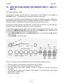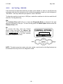
1
ELECTRONIC WASHING MACHINE
GWL11 / IWL12 / IWL15
PHASE 6 Series 11 / 12 120v 60Hz
Supplementary manual to be used
in conjunction with
GWL03 Service Manual – 426348
(including a complete new set of
DETAILED FAULT CODES)
517766B
517766B
October 2004
FISHER & PAYKEL
ELECTRONIC WASHING MACHINE- MODELS
GWL11
IWL12
IWL15
plus fault codes for GWL03, GWL08, GWL10
November 2002:
March 2003:
May 2004:
October 2005:
Repaginated (simplified page numbers) and alterations to sections 12
and 13.7
Added new fault code (66), user warnings and diagnostics table (16.3).
Added new model variant (IWL12) throughout relevant sections of
manual.
Added new model variant (IWL15) throughout relevant sections of
manual.
Fisher & Paykel Appliances
78 Springs Road, East Tamaki,
Auckland, New Zealand
PO Box 58-732, Greenmount,
Auckland, New Zealand
Phone 00 64 9 273 0640,
Fax 00 64 9 273 0649
Fisher & Paykel Appliances Inc.
27 Hubble,Irvine
California 92618
USA
Phone 1-888-9FNP-USA or
(1-888-936-7872),
Fax 949-790-8911
517766B
October 2004
CONTENTS
12. WHAT PHASE, SIZE & MODEL IS YOUR SMARTDRIVE ? ........................................4
13. SPECIFICATIONS........................................................................................................5
13.1 Finish.....................................................................................................................5
13.2 Dimensions............................................................................................................5
13.3 Maximum Capacity (Full Load) (AS 2040) .............................................................5
13.4 Water consumption per fill with clothes load using the Bern Clothes Washer
Study .....................................................................................................................5
13.5 Water fill temperature (Approximate Factory Settings) ..........................................6
13.6 Wash Motor ...........................................................................................................6
13.7 Pump Motor 120V AC 60Hz (SELNI).....................................................................6
13.8 Water Valves .........................................................................................................6
13.9 Thermistor .............................................................................................................6
13.10 Basket Speed ........................................................................................................6
13.11 Water Conservation Rating ...................................................................................6
13.12 Fabric Softener Dispenser .....................................................................................7
13.13 Electric Supply.......................................................................................................7
13.14 Use and Care Compact Disc .................................................................................7
13.15 Diverter Valve ........................................................................................................7
13.16 Lid Lock .................................................................................................................7
14. INTRODUCTION ..........................................................................................................8
14.1 Electronics .............................................................................................................8
14.2 Stand by mode ......................................................................................................8
14.3 Water Temperature Sensing .................................................................................8
14.4 Water Valves .........................................................................................................9
14.5 Stator.....................................................................................................................9
14.6 Pump ...................................................................................................................10
14.7 Lid-Lock ...............................................................................................................11
15. SIZE SETTING MODE FOR SERIES GWL11 / IWL12 / IWL15 .................................12
15.1 Size setting – GW...................................................................................................12
15.2 Size Setting - IW..................................................................................................13
16. DIAGNOSTIC MODE..................................................................................................13
16.1 GW (Ecosmart)....................................................................................................13
16.2 IW (Intuitive) ........................................................................................................14
16.3 SmartDrive Diagnostic Table - GW Only .............................................................15
16.4 User Warnings - GW ...........................................................................................15
16.5 Data Display - IW.................................................................................................20
16.6 Drain Pump Test - GW & IW ...............................................................................21
16.7 Water Valve Test - GW & IW...............................................................................22
16.8 Restart Feature – GW .........................................................................................22
16.9 Recycle Feature – GW ........................................................................................24
17. WIRING DIAGRAM.....................................................................................................26
18. READINGS FROM MODULE .....................................................................................27
Pump/Motor....................................................................................................................27
RPS................................................................................................................................27
Display ...........................................................................................................................27
Therm.............................................................................................................................27
Lid Lock / OOB...............................................................................................................27
Diverter Valve.................................................................................................................27
19. DETAILED FAULT CODES ........................................................................................28
FAULT DESCRIPTIONS ................................................................................................29
517766B
May 2004
12. WHAT PHASE, SIZE & MODEL IS YOUR SMARTDRIVE ?
PHASE
YEAR
PHASE 6 2002
Series 11
(GW)
Series 12 2004
(IW Eco)
2005
DISPLAY TYPE
US 120V
IW Intuitive
FRONT PANEL COLOURS
Pale blue panel, blue & white
buttons.
Opaque green panel with white
raised buttons and LCD screen
MODEL
NUMBERS
GWL11
MOTOR
CONTROLLER
Brown, aircooled
IWL12
GW & IW have a
thermistor in the
mixing chamber.
White panel with blue raised buttons IWL15
and LCD screen
IDENTIFIER
Green background
favourite, permanent press
wool washables, softener rinse
White with LCD display,
SIZE
Large
CAPACITY
(8 kg) 17.6lb
COMPONENTS
MODEL
TYPES
Inlet valves 24v
ecosmart
64 ohms.
(recirc),
Stator 16 ohms Intuitive eco
per winding.
(recirc)
Lid lock 73 ohms
Selni pump 7
ohms. (all @
20°C) 68 °F
DIMENSIONS
650 x 650 x (1020 – 1060 h)
25 ½ in. x 25 ½ in x (40 in – 41.¾in h)
Note: Phase 6 machines are a maximum of 1.5 inches (lid to floor) higher than phases 4 and 5.
- 4 -
517766B
May 2004
13. SPECIFICATIONS
13.1
Finish
Cabinet Pre-paint (Polyester)
Touch-Up Paint: White #503086
Lid ABS Co-injected, one piece
Console ABS with ABS insert for display control
Inner bowl stainless steel grade 430T
Outer bowl Polypropylene
Agitator Polypropylene
Top Deck Polypropylene
13.2
Dimensions
GWL11 / IWL12 / IWL15
Height to lid
Open
(1410 mm – 1440 mm)
Closed
(950 mm – 980 mm)
Height to console (1010 mm – 1050 mm)
Width
(650 mm)
Depth
(650 mm)
55.5 in – 56.6 in
37.4 in – 38.5 in
39.7 in – 41.3 in
25.5 in
25.5 in
Note: Exact height of the SmartDrive is dependent on how far the feet are inserted into the
base of the machine.
Inlet hose length
Weight:
Packed
Unpacked
13.3
(57.5 kg) 126.5 lb
(51.0 kg) 112 lb
Maximum Capacity (Full Load) (AS 2040)
Dry Weight
13.4
“L” models
(1200 mm) 47.2 in
(8kg) 17.6 lb
Water consumption per fill with clothes load using the Bern
Clothes Washer Study
Load Size (lb)
1
3
5
7
9
11
13
15
Total H2O gal
9.4
18.9
24.5
24.6
29.2
34.9
34.6
34.3
- 5 -
517766B
13.5
May 2004
Water fill temperature (Approximate Factory Settings)
GW / IW
Hot
(60oC) 140° F
Hot / Warm
(50oC) 122° F
Warm
(40oC) 104° F
Warm / Cold
(35oC) 95° F
Cold Plus
(20oC) 68° F
Cold
Supply temperature
Recommended hot water inlet temperature 65°C (Max) 149°F
13.6
Wash Motor
Electronically commutated direct drive 3 Phase brushless DC Motor
Motor Resistance per Phase 16 ohms @ (20°C) 68°F
13.7
Pump Motor 120V AC 60Hz (SELNI)
Thermal cut-out fitted
Flow Rate
Pump motor resistance
13.8
(24 litres per minute) 6.3 gal / min
7 ohms @ (20°C) 68°F
Water Valves
24 Volts DC
Digital Valve
Resistance 64 ohms @ (20°C) 68°F
Flow Rate (10 litres per min) 2.6 gal/min
Resistance 64 ohms @ (20°C) 68°F
Flow Rate (16 litres per min) 4.2 gal/min
Proportional Valve
Operating pressures
Maximum 1034 kPa
Minimum 20 kPa
(150 PSI) 1034 kPa
(5 PSI) 34 kPa
Low flow can affect the digital valve (Hot) and create seating problems with the seal.
13.9
Thermistor
NTC-type temperature sensor
13.10
Basket Speed
Fast Spin
Medium Spin
Slow
Stir Speed
13.11
Resistance 10,000 ohms @ (25°C) 77°F
1,000 RPM
700 RPM
300 RPM
25 RPM
Water Conservation Rating
GWL11 - AAA
IWL12 - AAAA
IWL15 - AAAA
- 6 -
517766B
May 2004
13.12
Fabric Softener Dispenser
Dosage
75cc
13.13
Electric Supply
Operating Voltage
Maximum Current
13.14
110/120V AC 60Hz
7.0 amps
Use and Care Compact Disc
PN 420350 Compact Disk GWL11-IWL12 US
USA
Replaces video on GWL 10
PN 420353 Compact Disk IWL15
13.15
Diverter Valve
Resistances
13.16
0.7KΩ to 2.5KΩ
Lid Lock
PN 420036P
Resistance range 73 ohms +/- 5 ohms
PN 420429
Resistance range 63 ohms +/- 10% @ 20oC (68oF)
Normally low voltage, potentially 230V if harness is grounded on the cabinet!
- 7 -
517766B
May 2004
14. INTRODUCTION
MODEL: GWL11 Ecosmart / IWL12 - IWL15 Intuitive Eco
This Service Supplement contains information on the Product Specifications, Diagnostic
Mode and the Detailed Fault Codes for Phases 4, 5 and 6, being Series 8, 10 and Series
11 / 12 machines respectively.
14.1
Electronics
The electronics for Series 11 / 12 are air-cooled in the same way as the Phase 5 (series
10) machine. This has changed from being water cooled as in earlier models. This has
been made possible by changes to the stator winding which allows a lower current through
the electronics and the use of the latest low loss, semi-conductor-switching device.
Electronic modules are not inter-changeable between models. The different modules for
the different models can be identified by their colour. L03 (green), L08 phase 4 modules
(yellow) and L10, phase 5 GW modules are grey. The new L11/L12/L15, phase 6
modules, GW are coloured brown.
GW/IW p/n 420094,
Motor controller
&
GW display
GW & IW Motor controller
Motor controller
&
IW display
It is important not to mix the different coloured modules as they are not compatible
and the washing machine will not work.
The latest module is similar to the series 10 module. The difference is that the terminals
are pushed on sideways at the top of the module.
The Series 11 / 12 module now has a 7 position connection for the display and a 4 position
connection for the Lid Lock / OOB.
14.2
Stand by mode
If a Series 11 / 12 machine has not received any instructions for 10 to 15 minutes after
being switched on at the power point or after completing the cycle, it will automatically go
into a low power Stand By mode, same as the Series 10 SmartDrive. Before entering the
Diagnostic or Option Adjustment modes, the machine must be taken out of the Stand By
mode. To do this, the power button will have to be pressed on and off or the machine
turned off and on at the power point.
14.3
Water Temperature Sensing
The thermistor for sensing water temperature in the ecosmart is located in the inlet
chamber and is available as a separate spare part under part number 479164P. See
specifications for the temperature / resistance readings.
- 8 -
517766B
14.4
May 2004
Water Valves
The Series 11 / 12 machines use different water valves to the Series 8 and 10 machines.
The valves are essentially the same (24 volts) but now have US standard threads which
are not interchangeable with previous models of SmartDrive washing machines,
especially the early LO3’s which are 12V with posilock connectors.
It is suggested when replacing a valve to use the same part number or superseded
number, leaking may occur if unlike threads are attached to inlet hoses.
The terminals are the “RAST 2.5” system. Extra care must be taken to ensure these
connections are plugged in squarely to avoid damage to the terminals.
There are two types of coil orientations possible on these valves, however the fittings are
identical. When removing the harness plug from the valve, a small retaining clip must be
released. The series 8 and 10 machines have these valves with the retaining clip located
on the solenoid behind the plug. Harness removal is a blind action.
14.5
Stator
The stator resistance of the Phase 6 is 16 ohms per phase, same as the previous phase 5,
which changed to allow for a lower current through the electronics. This stator is not
interchangeable with the previous models and can be identified by smaller terminal
connections. The rotor has not changed and can be used for all models of SmartDrive.
RED
BLUE
32
YELLOW
32
16
STAR POINT
16
16
32
SERIES 11 STATOR RESISTANCE
- 9 -
517766B
14.6
May 2004
Pump
The pump now uses a vortex impellor, which reduces the operating sound levels at the
end of the drain cycle. The new pump is a dedicated 110V 60Hz Selni pump. The way the
pump is controlled has changed. During the drain cycle the pump is stopped and started
quickly every 10 / 15 seconds.
The pulsing on and off of the drain pump only occurs when the basket is floated.
Changing the factory setting (GW Machine only):
Pulsing can be turned off if a higher head height is required (7 feet max), however the
possibility of pump blockage and Suds lock increases, which in turn affects the required
head height.
Enter “SIZE SETTING” mode (TEMP UP and POWER) this should be familiar when
changing modules and or displays.
The REGULAR cycle button toggles between having this feature disabled or enabled.
The REG LED shows the current status, when the LED is on in this mode the pulsing is
disabled. No other settings will be affected by this change and the setting will be saved in
eeprom. Power off in the same manner as with size setting to retain the setting.
If dual pumps were to be fitted, this feature should be used where the intermediate head
height is above 5 feet. The pulsing function is most effective in standard head height
situations (up to 6 feet).
Note:
If the pump has blocked/jammed and the thermal overload has gone open circuit, just
remove the blockage from the pump. The module and the pump should still be okay. If
the pump windings are water damaged, the pump will quickly overheat and cut off again.
The pump must be replaced in this case. (If the pump shorted to earth, it is possible that
the module could short out on series 10 machines). Series 11 should not have this
problem. The pump is not powered through the motor controller as with the phase 5
products. Series 11 phase 6 machines do not utilise the pump to dump energy. This
change also reduces the potential for failure.
It is important to check the pump windings thoroughly for water damage. It is possible for
the resistance of a water-damaged pump to be normal, however the inductance of the
pump can change causing it to overheat and cut out. There are new fault codes in the
system that now relate to the pump circuit and its extended function.
- 10 -
517766B
14.7
May 2004
Lid-Lock
On the Series 11 /12 SmartDrive there is now a lid lock.
During the spin and drain out part of the cycle prior to
spray rinsing, the lid will lock down until the completion
of the spin. Once the spin has completed, the lock will
release and the lid can be opened. The Lid Lock LED
will illuminate when locked.
A lock icon will be displayed on the IW model when
the lid lock is activated.
If the lid lock fails in the closed position the removal process is as follows:
The locked lid can be lifted on the sides enough to allow the lid buffers to be removed.
This will allow the screws holding down the top deck to be unscrewed. The top deck can
then be lifted up, removing the lid lock screw will allow the lid lock housing to be replaced.
Un-clip the clear cap from the housing and disconnect the Rast connection. Clip the new
housing in and re-assemble.
If the harness is damaged, replacing it requires the following method.
Remove the lid from the top deck assembly. The Console will then need to be removed to
access the wiring connection to the motor controller if the wiring loom is replaced. This
harness is also part of the harness to the OOB switch and the motor controller will need to
be lifted to remove and replace it. Remember to secure the wire into the retainers under
the top deck, or damage may occur during operation.
Note:
If the power supply is cut during the spin cycle, the machine will keep the lid locked until
the rotor has ceased to turn (3 to 15 secs). Only then will it release the lock, the motor is
acting like a generator and allows the lock to stay energised under the baskets inertia via
the motor controller. In a brown out situation the machine will restart at the start of
whatever cycle it was doing and continue the wash. The lid lock would then be reactivated
if it happened to be on a spin cycle.
- 11 -
517766B
May 2004
15. SIZE SETTING MODE FOR SERIES GWL11 / IWL12 /
IWL15
15.1 Size setting – GW
The difference between the GW Series 11 and previous GW machines is the position of
the Power button. The sequence for sizing the modules is the same.
It is important to set the size switch setting into the Motor Controller’s memory whenever a
replacement Motor Controller and or IW Display Module is fitted to SmartDrive. Failure to
do this will result in SmartDrive faulting with fault code 9 (Size switch error).
Accessing size setting mode is the best way to check the size for GW. The size setting of
SmartDrive may be checked in Diagnostic mode for all phases.
To set the size switch turn the power on at the power point and off at the console. Press
and hold the TEMPERATURE UP button then press the POWER button. SmartDrive will
give 4 short beeps and the pattern of LEDs will change.
• Press SPIN SPEED UP button, the SPIN HOLD LED is on for (8.0kg) 17.6lb (650mm
wide). 25.5 in
• Press POWER to exit this mode.
If the size setting is wrong SmartDrive will have the following settings incorrect: •
•
•
•
•
The Auto Water Levels chosen by SmartDrive may be wrong.
The High Water Level may be wrong by as much as 1.5 in.
The flow rate for inlet water, normally (3 litres or 0.8 gal per minute), may be set
incorrectly.
The wash profile controls the strength of the agitator. This could result in poor wash
performance or splash over.
Water saver settings.
- 12 -
517766B
15.2
May 2004
Size Setting - IW
To set the size, turn the power on at the power
point and off at the console. Press and hold the
FABRIC CARE button, then press the POWER
button. This will present a set of options in the
LCD screen.
The LCD screen has within it a number of
options. Push the Adjust button to highlight
650mm (L). Pushing the POWER button will
lock the “size” into the module’s memory.
16. DIAGNOSTIC MODE
16.1
GW (Ecosmart)
Turn the power on at the power point but off at the machine. Press and hold the WASH
TEMP DOWN button and then the POWER button until the machine gives 2 short beeps
and lights up. Release buttons when the beeps indicate diagnostic mode has been
entered.
Note: The power button is relocated to the left of the panel but central to the console, not
on the right hand side as with all previous GW SmartDrive machines.
- 13 -
517766B
May 2004
Last fault can be found by pressing the SPIN SPEED UP button three times. The HOLD
and SLOW lights should be illuminated. Binary can then be read from the wash progress
lights. Fault code 49 is shown above, 32+ 16+ 1 = 49 which is a cold water valve fault.
Binary code is read from the Wash Progress lights.
128 64
32
16
8
4
2
ο
ο
ο
ο
ο
ο
ο
16.2
1
ο
IW (Intuitive)
The DIAGNOSTIC MODE in the IW (Intuitive) incorporates both tests for the drain pump
and the water valves, and also the data display mode (see section 16.5).
To enter the DIAGNOSTIC MODE, turn the power on at the power point and off at the
console. Press and hold the LIFECYCLES button and then the POWER button.
The machine will give 2 short beeps and the LCD screen will go blank. Then press
OPTIONS for data retrieval.
Note: Make sure that the buttons are released after the beeps, or the machine will turn
itself out of the diagnostic mode.
- 14 -
517766B
16.3
May 2004
SmartDrive Diagnostic Table - GW Only
To use this table, firstly enter Diagnostic Mode. The different levels of information can be
extracted by using the Spin Speed up and down buttons.
Diagnostic
Mode
0
1
2
3
Spin Speed LEDs
Fast Med Slow
OFF OFF OFF
OFF OFF OFF
OFF OFF ON
OFF OFF ON
Hold
OFF
ON
OFF
ON
4
5
6
7
8
9
10
11
12
13
14
15
OFF
OFF
OFF
OFF
ON
ON
ON
ON
ON
ON
ON
ON
OFF
ON
OFF
ON
OFF
ON
OFF
ON
OFF
ON
OFF
ON
16.4
ON
ON
ON
ON
OFF
OFF
OFF
OFF
ON
ON
ON
ON
OFF
OFF
ON
ON
OFF
OFF
ON
ON
OFF
OFF
ON
ON
Diagnostic Info Displayed
Last User Warning Number
Last User Warning Cycle Position
HVDC setting (used by auto WL sense agitate)
Fault Code at last fault (if within the last 8
cycles)
OOB status
Cycle count at last fault (low byte)
Cycle count at last fault (high byte)
Cycle position at last fault
Water Temp (deg C)
Cycle count (low byte)
Cycle count (high byte)
Motor speed (rpm/10)
Water Level
EEPROM version number
Software Version number
(F&P development use only)
User Warnings - GW
There are a number of warnings, which are generally caused by the user or poor
installation. The user generally can correct these warnings. SmartDrive signals user
warnings by flashing LEDs and a rippling set of 5 beeps repeated every 6 seconds. This is
the same tone that is heard when SmartDrive is first plugged into the mains power. Some
warnings are indicated by the wash progress LEDs flashing and no user warning tone,
(Restart or Recycle mode). Most of this information is available to the user in the ‘Use and
Care Manual’
- 15 -
517766B
16.4.1
May 2004
Insufficient Hot Water (Hot Water LED flashing)
This warning is indicated by the hot water LED flashing. SmartDrive will also
be making a rippling set of 5 beeps repeated every 6 seconds. The hot water
is not connected or the water temperature is too low. NB. This warning mode
does not cause the product to PAUSE.
1. Check that the hot water is connected and that the tap is turned on. If your
product is set for 'controlled cold' hot water may still be required for a cold
wash.
2. Check that the water temperature is not too low. The water temperature
may need to be 60oC (140oF) for a hot wash.
3. Check that the hot water inlet is not connected to the cold water supply.
4. Check that the filter on the hot inlet hose is not blocked.
5. Motor Controller.(Phase 1 to 4). Thermistor (Phase 5). The temperature sensor has
failed. Replace motor controller.(Phase 1 to 4) Check the resistance of the thermistor.
Resistance is 12.5k ohms at 20oC (68oF). Replace if faulty. (Phase 5).
6. Check the size is set correctly.
NB. It is possible to get this warning when washing with cold water if the cold wash
temperature is set at 20oC (68oF) or more. Wash temperatures may be adjusted, see
section 7.1.
16.4.2
Insufficient Cold Water (Cold Water LED flashing)
This warning is indicated by the cold water LED flashing. SmartDrive will also
be making a rippling set of 5 beeps repeated every 6 seconds and the product
will be paused. The cold water is not connected or the flow rate is too low.
1. Check that the cold water is connected and that the tap is turned on.
2. Check that the flow rate is not too low. The product requires a minimum
flow rate of 3 litres per minute. Check that the filter on the cold inlet hose is
not blocked. If the installation has a flow rate below 5 litres per minute the
flow may be improved by using large bore inlet hoses p.n. 426123.
3. Taps may be connected the wrong way round.
4. Cold water temperature exceeds 35oC (95oF). NB. Phase 2-4. If cold water
temperature exceeds 40oC (140o) high purge motor controllers are
available. Contact your Technical Representative.
5. Phase 1-4. Motor Controller. The temperature sensor has failed. Replace motor
controller.
6. Phase 5. Thermistor. Check the resistance of the thermistor. Resistance is 12.5k ohms
at 20oC (68oF). Replace if faulty.
7. Check the size is set correctly.
- 16 -
517766B
16.4.3
May 2004
No Water (Both Hot and Cold Water LEDs flashing)
This warning is indicated by the cold and hot water LEDs flashing. SmartDrive
will also be making a rippling set of 5 beeps repeated every 6 seconds and
the product will be paused.
1. Check that the taps are turned on.
2. Check that the inlet hoses are connected.
3. Check that the flow rate is not too low. The product requires a minimum
flow rate of 3 litres per minute. Check that the filters on the inlet hose are
not blocked. If the flow rate is always low then fit large bore inlet hoses.
4. Check that the hot water is connected and that the tap is turned on. If your
product is set for 'controlled cold' hot water may still be required for a cold
wash.
5. Siphoning. Check the drain hose is not installed too low and is siphoning.
6. Check the size is set correctly.
16.4.4
Overloaded Product (High Water LED flashing)
This warning is indicated by the high water LED flashing. SmartDrive will
also be making a rippling set of 5 beeps repeated every 6 seconds and
the product will be paused. The product is overloaded.
1. Check that the product is not overloaded. This is more likely on a
smaller size product. Also it may be that the user has selected the
wrong water level this is more likely to be a LW or MW, which only
has 3 water levels.
2. Check that the rotating bowl assembly is not jammed to the agitator
with any foreign object that may be caught under the agitator skirt.
3. Check that the clutch teeth are not locked together with dirt,
detergent or lint. Check that the teeth are not broken.
16.4.5
Out of Balance (First Rinse or Final Spin and Current Spin Speed LED is
flashing)
This warning is indicated by a rinse or spin LED and the current spin speed LED flashing.
SmartDrive will also be making a rippling set of 5 beeps repeated every 6 seconds and the
product will be paused.
1. Generally this can be caused by a large load. SmartDrive will normally manage to
redistribute the load and spin. Under exceptional circumstances the user may need to
redistribute the wash load manually once the bowl is stationary.
2. Check that SmartDrive is correctly installed, is level and does not wobble.
3. Check the bias spring is fitted between the wrapper and the outer bowl.
4. Check the OOB lever, switch and bracket.
5. Check the switch operates correctly with a multimeter. Resistance should be less than
2 ohms.
6. Check the suspension is not catching or bouncy.
7. Check both balance rings on the inner bowl contain water.
8. The Motor Controller, (Display for Phase 1) should only be replaced if fault code 43.
- 17 -
517766B
16.4.6
May 2004
Suds (First Rinse LED is flashing or Final Spin LED is flashing)
This warning is indicated by a rinse or spin LED flashing. SmartDrive will also be making a
'rippling sound of 5 beeps repeating every 6 seconds' and the product will be paused. Too
much Detergent has been used and SmartDrive has a suds build up.
1. This is generally caused by too much detergent. Wait for suds to dissolve then rinse
clothes using a deep rinse.
2. Check that the pump is not partially blocked, or that the drain hose is not kinked.
16.4.7
User Warnings – IW
The Intuitive Eco is capable of diagnosing its own problems and if it has a problem it will
beep and display a message telling the customer what is wrong. If it is a problem that the
customer is capable of solving it will give a musical series of beeps every 5 seconds (the
same sound the machine makes when it is turned on at the wall) and will display one of
the following messages.
Note: The musical series of beeps is the same sound the washer makes when its turned
on at the wall.
IF YOUR INTUITIVE BEEPS FOR HELP
My load is OUT OF BALANCE
Wash load is out of balance.
Ensure the machine is stationary and manually redistribute the load.
Check machine is level.
I am not getting any HOT WATER
Hot water supply is not hot enough to maintain the wash temperature you have selected.
Select a lower wash temperature.
Inlet hose screens may be blocked.
There may be a kink in the hose.
Hot tap has not been turned on.
Inlet hoses connected to the wrong taps.
I am not getting any COLD WATER
Cold tap has not been turned on.
Inlet hose screens may be blocked.
There may be a kink in the hose.
Inlet hoses connected to the wrong taps.
Cold water temperature exceeds recommended limits.
The flow rate of the supply water is too slow.
I am not getting any WATER
The taps have not been turned on.
Inlet hose screens may be blocked.
The hoses may be kinked.
The drain hose is too low or the drain hose is pushed into the standpipe too far and the water is
siphoning out of the machine.
The flow rate of the supply water is too slow.
I am OVERLOADED
The machine is overloaded and can not agitate.
Ensure the machine is stationary.
Remove items until the remaining ones can move freely, or select a higher water level.
Check the machine is not syphoning.
I have TOO MANY SUDS
The machine has a suds build-up. (Too much detergent may have been used for the amount of soil
in the load).
- 18 -
517766B
May 2004
Wait for suds to dissolve (about 20 minutes).
Rinse clothes using a deep rinse.
I can’t LOCK THE LID
Make sure the lid is closed.
Press START PAUSE.
If the symptom persists call your Fisher and Paykel Dealer or Authorised Service Centre.
16.4.8
Demonstration Mode (GW & IW) - All LEDs flashing in patterns
These features are designed for in store demonstration purposes. SmartDrive can draw
attention to itself with a selection of flashing LEDs. In this mode SmartDrive cannot be
started.
GW: To Select DEMONSTRATION MODE press and hold the ADVANCE button, then
press the POWER button.
During the DEMONSTRATION display the LEDs will alternate between all on, LEDs
flashing, and all LEDs off. To return SmartDrive to normal operation, the mains supply
must be switched off. Some Phase 1-3 displays may inadvertently go into this mode if
affected by condensation.
IW: Press START/PAUSE and hold down then press POWER
The Demo Mode scrolls through a series of text, advertising the various features of the
product, while flashing the LEDs. The backlighting of the LCD display also flashes for the
first few seconds to attract attention.
It then shows several samples of the animations used during the wash, before repeating.
If any of the keys are pressed, Demo Mode stops, and the displays changes to normal “on”
mode, to allow the user to navigate around the menus, as they would normally if using the
product. In this mode the machine will not allow a normal cycle to start (it will raspberry if
Start/Pause is pushed).
After 30 seconds without a key press, the display automatically reverts back to Demo
Mode again.
To exit the Demo Mode the power has to be turned off at the wall and then back on.
- 19 -
517766B
16.5
May 2004
Data Display - IW
To enter the DATA DISPLAY screens, push the LIFECYCLES button again. This will
enable the out of balance switch to be tested, as well as giving access to the Detailed
Fault Codes and User Warning Faults. One of three displays will appear in the screen.
Use the buttons on the bottom of the display screen to toggle between these displays.
Options, up or down.
The Warning Status screen will display the
last USER WARNING FAULT that occurred
and will show at what part of the cycle it
occurred.
The User Warning Faults are as follows:
• No Taps
• Overloaded
• Out Of Balance
• Over Suds or water still in the machine
during spin
• No Hot Water
• No Cold Water
• Agitate Overloaded
The Machine Status screen displays the
status of the diverter and the out of balance
switch. It also displays the size setting of
the
machine,
and
the
thermistor
temperature.
HVDC is for on line testing in the factory.
Target temp is the temperature selected.
T is the actual temp of the inlet chamber
water.
- 20 -
517766B
May 2004
The Fault Status screen will display a code
for the last fault that has occurred in the
machine. It will also display how many
cycles ago that the fault occurred, and at
what part of the cycle.
See Detailed Fault Codes for servicing tips.
The fault code number can now be checked in the detail fault codes, to ascertain what
repairs may be necessary.
16.6
Drain Pump Test - GW & IW
GW
The Regular button activates the pump when in diagnostic mode. Enter diagnostics using
the same sequence as previous phases. The Power button is in the middle of the
console, not on the right hand side as with series 8 and 10 machines!
For testing the pump, the Regular button (ecosmart) will activate the regular light, which in
turn activates the pump. Pressing the button activates the pump. Pressing the button
again de-activates the pump.
IW
The Fabric Care button turns the drain pump on or off when in diagnostic mode.
Note: This feature can be helpful if the bowl is still full of water.
- 21 -
517766B
16.7
May 2004
Water Valve Test - GW & IW
GW
The water valves are activated in diagnostic mode. Pressing the Temp up button for Hot
valve (digital) and Temp down button for Cold valve (proportional) as with previous
models.
Pressing each button once will activate the valve. To de-activate the valve, press the
same button again. Caution: Do not leave the machine unattended when either or
both valves are operating. This is also good to use when installing machines. It takes
the shock out of the fittings and seals and allows checks for leaks on the inlet hoses both
machine end and tap end.
IW
The water valves are activated when in diagnostic mode. Pressing the How Dirty down
button will turn the Cold water valve on. Pressing the How Dirty up button will turn the hot
water valve on. You need to hold the buttons down to keep the water entering the
machine. This is also good to use when installing machines as it takes the shock out of
the fittings and seals and allows checking for leaks on the inlet hoses, both machine end
and tap or super-tub end.
16.8
Restart Feature – GW
For GW Restart setting, enter Diagnostics Mode with the power off at the machine but on
at the wall outlet. Press and hold the Wash Temp down button and then press the Power
button. 2 beeps will be heard when this mode has been entered successfully.
An illuminated LED on low water level will indicate the Restart feature is activated.
Using the low water level button this feature can be disabled for servicing and quick fault
diagnosis, or enabled when returning to the customer.
To make sure the phase 6 module retains the restart feature (when it has been disabled
for service reasons), press and hold the Advance button down at the same time when
pressing the Water level down button. A long beep will acknowledge the setting has been
retained in EE prom. Power off to retain selection as with size switching.
When the machine is first turned on:
1.
If none of the 5 left most green wash progress LED’s are on, the restart feature
is on.
2.
If all 5 of the left most green wash progress LED’s flash, the restart feature is
off and SmartDrive will not restart automatically if a minor fault occurs during
normal usage.
With the RESTART feature on:
1.
2.
3.
If a fault occurs in the machine, the diagnostic system will detect it. However,
instead of displaying a fault code immediately, the machine will try to RESTART.
If the fault was only of a temporary nature, the machine will restart and finish the
cycle.
If there is a continuous fault the machine will try to RESTART a number of times.
This process could take up to 8 minutes depending on the type of fault. After this, if
the machine still cannot restart, the fault code is displayed and the machine will
beep continuously.
- 22 -
517766B
May 2004
NOTE - This feature is designed as a service aid only and should be left ON in the
customer’s home. To return to normal operation, and to reset the RESTART feature to the
factory setting, switch the machine off at the wall or disconnect from the mains supply.
16.8.1
Restart Feature – IW
IW Restart setting can be accessed when in diagnostic mode, pressing the Options button
will bring up the Control Option screen. The LCD screen will display the following:
The machine leaves the factory with the
RESTART set to the ON position (as shown
here), which is indicated in the screen by
the word RESTART highlighted. To turn the
RESTART feature OFF, push the Home
button. This will remove the highlight from
the word RESTART. When the machine is
being serviced, it is more convenient to turn
the RESTART feature OFF. This will allow
any fault in the system to show up
immediately.
Hot Tub Flag
With the RESTART feature on:
1.
2.
3.
If a fault occurs in the machine, the diagnostic system will detect it. However,
instead of displaying a fault code immediately, the machine will try to RESTART.
If the fault was only of temporary nature, the machine will restart and finish the
cycle.
If there is a continuous fault the machine will try to RESTART a number of times.
This process could take up to 8 minutes depending on the type of fault. After this, if
the machine still cannot restart, the fault code is displayed and the machine will
beep continuously.
Whether or not the RESTART feature is on is indicated during normal use of the machine
as follows:
1.
2.
If none of the 5 green “HOW DIRTY” LED’s are on, the RESTART feature is on.
If the 5 green “HOW DIRTY” LED’s are flashing, the RESTART feature is off.
NOTE - This feature is designed as a service aid only and should be left ON in the
customer’s home. To return to normal operation, and to reset the RESTART feature to the
factory setting, switch the machine off at the wall or disconnect from the mains supply.
- 23 -
517766B
16.9
May 2004
Recycle Feature – GW
At the end of servicing, the machine may require an extended test where the machine can
be left to complete a number of wash cycles. By turning on the RECYCLE feature the
machine will continuously repeat the wash cycle until the RECYCLE feature is turned off.
To activate or deactivate the RECYCLE feature: Enter diagnostic mode, the WATER
LEVEL UP button toggles this feature on and off. If the Medium Water Level LED is on the
RECYCLE feature is on, if the Medium Water Level LED is off the RECYCLE feature is off.
Whether or not the RECYCLE feature is on is indicated during normal use of the machine
as follows:
When the machine is first turned on:
1.
2.
If none of the 3 right most wash progress LED’s are on, the recycle feature is off.
If all 3 of the right most wash progress LED’s flash, the recycle feature is on and
SmartDrive will continuously recycle.
NOTE - This feature is designed as a service aid only and should be OFF in the
customer’s home. To return to normal operation, and to return the recycle feature to the
factory setting, switch the machine off at the wall or disconnect from the mains supply.
16.9.1
Recycle Feature - IW
In the Control Option mode (as for setting the RESTART feature), pushing the Adjust
button to highlight the word RECYCLE will toggle this feature on and off. At the end of
servicing, the machine may require an extended test where the machine can be left to
complete a number of wash cycles. By turning on the RECYCLE feature the machine will
continuously repeat the wash cycle until the RECYCLE feature is turned off.
Whether or not the RECYCLE feature is on
is indicated during normal use of the
machine as follows:
When the machine is first turned on:
1.
If none of the Fabric Care LED’s are
on, the recycle feature is off.
2.
If all of the Fabric Care LED’s flash,
the recycle feature is on.
Hot Tub Flag
NOTE - This feature is designed as a service aid only and should be OFF in the
customer’s home. To return to normal operation, and to return the recycle feature to the
factory setting, switch the machine off at the wall or disconnect from the mains supply.
- 24 -
517766B
16.9.2
May 2004
Hot Tub Flag – GW & IW
If the machine has been filled with the hot water valve utilised (ie. warm or hot fill) and has
not had a cold rinse; the electronics will not allow the machine to spin up to its full speed of
1000 RPM. It will only allow the spin speed to reach 700 RPM.
To allow the machine to spin up to 1000 rpm, restart the machine at cold rinse and this will
reset the Tub flag detecting.
GW
The Softener Rinse LED will be on when the Diagnostic Mode is selected if the spin
speed is restricted to 700 rpm. To clear this flag press the Wash Option button below the
Softener Rinse LED.
IW
To remove this flag, enter the Control
Option mode and push the Options Up
button to take the black shading out of the
box Hot Tub Flag, or put the machine
through a complete final rinse.
Hot Tub Flag
NOTE: The drain pump test, water valve test, restart, recycle and hot tub flag features can
be accessed from any level in the diagnostic mode.
- 25 -
517766B
May 2004
17. WIRING DIAGRAM
- 26 -
517766B
May 2004
18. READINGS FROM MODULE
Expected Readings on 120V Motor Controller
Pump/Motor
Winding resistance check,
phase to phase
(already in service manual) 32 ohms
120 VAC
RPS
C
B
A
15v ∅V
Should always be 15V DC
Individual phases should be either 15V or ∅V, will
change when the motor turns
Display
CLK DAT STR ∅V COMS 5v SM
Sleep Mode
On:
2.5V:
0.1V
Therm
Resistance check with power off.
12.5k ohms at (20°C) 68° F
∅V ∅V Therm
Lid lock drive
Lid Lock / OOB
Pulses up to 30V when locking,
when lid locked, sits at approx 10V DC
∅V OOB
Diverter Valve
Approx 100 V AC when on, across the terminals, not strictly AC, rectified mains
Fluke meters read approx 100 V AC or 220 V DC (rms) depending on meter.
- 27 -
517766B
May 2004
19. DETAILED FAULT CODES
DETAILED FAULT CODES
FOR
MODELS
Phase 3
Phase 4
Phase 5
Phase 5 IW
Phase 6
Phase 6 IW
GWL03
GWL08
GWL10
IWL10
GWL11
IWL12 / IWL15
INTRODUCTION
The format for fault description in this booklet follows the Primary, Secondary, Tertiary and
Quaternary fault source system. These sources have mostly been arranged in order of
most likely source of fault, but in some cases the sequence has been modified to aid the
servicing procedure.
It should be noted that the fault source Pump System includes the pump and drain hose
assembly.
Fault code shows the last recorded fault. Always confirm fault.
- 28 -
517766B
May 2004
FAULT DESCRIPTIONS
1.
(00000001)
Phase 1 - Display Module Fault
Phase 2 to 6 - Motor Controller Module Fault
The Motor Controller Module (Display for phase 1) has encountered an error when
writing to an Eeprom address.
Primary Source: Motor Controller module. (Display Module for Phase 1)
Action:
Replace Motor Controller module. (Display Module for Phase 1)
2.
(00000010)
Phase 1 - Display Module Fault
Phase 2 to 4 - Motor Controller Module Fault
An error has been encountered when trying to read the pressure sensor.
Primary Source: Motor Controller module. (Display Module for Phase 1)
Action:
Replace Motor Controller module. (Display Module for Phase 1)
3.
(00000011) Phase 1 to 6 Motor Controller Module Fault
The Motor Controller Module has found a memory error.
Primary Source: Motor Controller module.
Action:
Replace Motor Controller module.
4.
(00000100) Phase 1 - Communications Fault
The Motor Controller has had difficulty communicating with the Display Module
Primary Source: Motor Controller module.
Action:
1. Turn off at the wall and on again after 5 seconds and try again.
2. If still faulty, replace the Motor Controller
3. Replace Display Module. If the new Display Module corrects the
fault, then refit the original Motor Controller.
5.
(00000101) Phase 1 - Communications Fault
The Display Module has had difficulty communicating with the Motor Controller.
Primary Source: Display Module.
Action:
Turn off at the wall and on again after 5 seconds and try again.
1. Check connections of the 12 way harness for bad contacts,
corrosion etc.
2. Check for moisture in the console area. Dry out if necessary
2. If still faulty, replace the Display Module
3. If still faulty, replace the Motor Controller. If the new Motor
Controller corrects the fault, then refit the original Motor Controller.
6.
(00000110) Phase 1 – Display Module Fault
Phase 2 – 4 Motor Controller Module Fault
The Motor Controller module (Display Module for Phase 1) has received an
incorrect signal from the pressure sensor.
Primary Source: Motor Controller module. (Display Module for Phase 1)
Action:
Replace Motor Controller module. (Display Module for Phase 1)
- 29 -
517766B
May 2004
7.
(00000111) Phase 1 to 6 - Display Module Fault
The Display module has found a memory fault.
Primary Source: Display Module.
Action:
Replace Display module.
8.
(00001000) Phase 1 - Display Module Fault
The Display micro has not been able to start up correctly.
Primary Source: Display Module.
Action:
Turn off at the wall and on again after 5 seconds and try again. If still
faulty replace the Display Module.
9.
(00001001) Phase 1 to 6 Size Switch Error
The Display size switch setting does not match that stored in the memory.
Primary Source: Display Module Phase 1,2 & 3.
Action:
If the Display module for Phase 1, 2 or 3 has just been inserted into a console
housing, then check that the two size switch plungers accurately locate onto the
console housing. If this fault has appeared during normal operation of the machine,
check for condensation damage, check the size switch or replace the Display
module.
Secondary Source:
Motor Controller module.
Action Phase 1, 2 &3:
If the Motor Controller module has been changed from one size machine to another,
then the size switch settings in the memory will have to be reset. This can be done
by entering and exiting the Option Adjustment mode.
Push and hold
START/PAUSE then push POWER button.
Action Phase 4 Series 8, Phase 5 Series 9 / 10 & Phase 6 Series 11:
Reselect the size of the machine by using the SIZE SETTING MODE. Push and
hold the WATER TEMP UP button then press the POWER button. To select the
size of the machine, push the temperature up button until the cold LED is on for
5kg machines, push the water level up button until the low water level LED is on for
the 6kg machines, push the SPIN SPEED UP button until the hold LED is on for 7kg
machines.
10.
(00001010) Phase 1 to 6 Temperature Sensor (Thermistor) Error
The temperature sensor may be open circuit or the ambient temperature is below
minus (10oC) 50° F. This fault is only applicable in the Intuitive Washer and the GW
models.
Primary Source: Thermistor.
Action:
Replace Thermistor.
11.
(00001011) Phase 1 to 6 - Pressure Sensor Fault
While measuring the water level, the Motor Controller micro has detected a
negative pressure. Reconnecting the pressure tube to the pressure sensor while
the bowl has been partly filled with water may have caused this.
Primary Source: Pressure Tube.
Action:
- 30 -
517766B
1)
2)
May 2004
Check bowl is fully pumped out. Remove pressure tube from pressure
sensor, clear pressure tube of any water and reconnect tube.
If fault is still present, replace the Motor Controller module.(Display Module
Phase 1)
12.
(00001100) Phase 1 to 6 - Flood Protection Error
The Motor Controller module has found the water level to be above the flood level
and tried to pump the excess water out. (Under extremely high flow rate conditions
the machine may overfill during the “top-up” routine in agitate.) After pumping for
30 seconds, it has been unable to lower the water level below the flood level. Either
the water valves have stuck on and are letting water in at a flow rate that is higher
than the pump can handle, or the pump is blocked and can’t remove the excess
water.
Primary Source: Water Valves.
Action:
If the water valves are on continuously, check that the water valves turn off
mechanically (remove power from machine).
Secondary Source: .Pump system
Action:
Check pump for blockage and drain hose for correct height and kinking
Tertiary Source: Motor Controller module. (Display Module Phase 1)
Action:
If water valves are being driven on electrically, replace Motor Controller
module. (Display Module Phase 1)
13.
(00001101) Phase 1 – Pump Fault
The Display module has detected that the pump is on when it should be off.
Action:
1.
The pump is fitted with a thermal cut out device. Check if this device has
been activated. If it has wait until the pump cools down before restarting.
Check for any pump blockage and condition of pump before attempting to
restart. ie. pump seizure.
2.
Check for open circuit pump windings. Check the resistance of the pump.
3.
Check the pump harness or the connectors for an open circuit.
4.
Replace the Display Module.
14.
(00001110) Phase 1 – Pump Connection Fault
The Display Module has detected that the pump is not on when it should be.
Primary Source – Pump
Action:
1.
The pump is fitted with a thermal cut out device. Check if this device has
been activated. If it has wait until the pump cools down before restarting.
Check for any pump blockage and condition of pump before attempting to
restart. ie. pump seizure.
2.
Check for open circuit pump windings. Check the resistance of the pump.
3.
Check the pump harness or the connectors for an open circuit.
4.
Replace the Display Module.
15.
(00001111) Phase 1 – Display Module Fault
The Display Module has read an incorrect voltage on the pump circuit
Primary Source: Display Module
Action:
- 31 -
517766B
May 2004
Replace the Display Module.
Note: If SmartDrive is running at well below its rated supply voltage and the pump
has operated for more than 4 seconds at the voltage this fault will also appear.
17 – 20. (00010xxx) Phase 1 – Display / Motor Controller out of Sequence
22 – 23. (000101xx) Phase 1 – Display / Motor Controller out of Sequence
Primary Source: The Display Module and Motor Controller are running out of
sequence.
Action:
Turn the SmartDrive off at the wall and then back on again in 5 seconds. Restart.
If the fault persists, disable auto restart feature and retest. A new fault code will
appear, carry out actions necessary to fix this new fault.
25.
(00011001) Phase 5 IW – LCD Initialisation Error
The Intuitive Display has detected a problem with the LCD. Liquid Crystal Display
Primary Source: IW Display Module
Action:
Replace IW Display Module
28 – 30. (000111xx) Phase 1 – Display / Motor Controller out of Sequence
Refer to fault code 17
32.
(00100000) Phase 1 – Pump Circuit Error
The Display Module has detected that the pump is on when it is off.
Primary Source: Display Module
Action:
1.
Check for moisture in the console area.
2.
Replace the Display Module.
- 32 -
517766B
May 2004
33.
(00100001) Phase 1 – Water Valve Fault
The Module has detected a water valve fault.
Primary Source: Water Valve connection
Action:
Check that both valves are connected up properly.
Secondary Source: Water Valve coil faulty
Action:
1.
Check the valve coils are not open circuit.
2.
Replace Display Module if the valve coils are not faulty.
34.
(00100010) Phase 1 – Brake Resistor Fault
The circuit that controls the braking of the motor is faulty.
Primary Source: Motor Controller
Action:
Replace Motor Controller
Secondary Source: Display Module
Action:
Replace the Display Module
If the Display Module corrects the fault, then refit the original Motor Controller.
35.
(00100011) Phase 1 – MC Reset Error
The Display Module has sent a false signal to the Motor Controller.
Primary Source: 12 way Harness Connection.
Action:
Check the 12 way harness connection between the display Module
and the Motor Controller.
Secondary Source: Display Module
Action:
Replace the Display Module.
36.
(00100100) Phase 1 to 6 - Water Leak Fault
The Motor Controller module has needed to top up the water level more than 4
times during agitate. This is excessive, as normally only one or two top ups are
required to replace the air that has escaped from a full load during agitate. The
most likely cause is that the machine is siphoning. The other alternative is that the
machine has developed a leak.
Primary Source: Pump System.
Action
1)
Check the height of the drain hose outlet. Minimum 33.4 in (850mm),
Maximum 47 in (1200mm).
2)
Check that the hose guide is fitted and check that the hose does not protrude
more than (20mm) ¾ in beyond the guide.
Secondary Source:
Mechanical.
Action:
1)
Check the pressure tube connections on the Tub and Motor Controller
module.
2)
Check that the drive shaft seal and the pump housing seal have not
developed a leak.
Tertiary Source: Motor Controller module.(Display Module Phase1)
Action:
Replace Motor Controller module.(Display Module Phase 1)
- 33 -
517766B
37.
level)
May 2004
(00100101) Phase 1 to 6 - Pump Blocked Error ( No change in the water
While draining, the water level reading from the pressure sensor has not changed
for over 3 minutes. There are three likely reasons for this fault. One is that the
drain hose or the pressure switch hose has been squashed or kinked and the pump
out rate has been dramatically reduced. The second possibility is that the pump is
partially or fully blocked. The third is that the pump is not operating due to Motor
Controller module, wiring or pump failure. This fault could also appear if the
machine is pumping to an unusually high head of drain hose or into an extended
length of drain hose. The Fourth possibility is a diverter valve fault or blockage,
water level is not altering as the diverter is stuck in the recirculation mode, giving
the module the appearance the pump is not lowering the water level.
Primary Source: Pump System.
Action:
1)
Check that the drain hose has not been kinked.
2)
Check the length of the drain hose and try to reduce the length if excessively
long. A 39 inch (1 metre) extension hose of the same diameter fitted to the
existing drain hose is the maximum allowable length.
3)
Check for open circuit windings in the pump. (Note: Pumps are fitted with a
thermal cut-out, which will reset on cooling.)
4)
If the Tub is empty of water, remove the pump from the pump housing and
check that it is not blocked. Also check the drain hose is not blocked.
5)
If the Tub contains water, then service the pump from the top of the machine
by removing the top deck and Basket. Bail out the water, remove the pump
cap and hood and clear the restriction.
Secondary Source:
Wiring.
Action:
1)
Check the pump harness is connected correctly to the pump.
2)
Check continuity of the pump harness.
Tertiary Source: Motor Controller module.
Action:
Activate the pump by operating the machine in spin mode. Check the pump
is rotating. If it is not operating, and Primary and Secondary checks have
been performed, then replace the Motor Controller module.
Note: Consider fitting Pump Hood Kit (WM013). If (5kg) 11lb SmartDrive fit splash
guard to pump.
Quaternary Source:
Diverter Valve failure (Phase 5 and 6 Eco’s )
Action:
Check the diverter valve, see fault code 51
38.
(00100110) Phase 1 to 6 - Pressure Sensor Fault
The Motor Controller module has recorded a water level of empty while it is
agitating. The water level must have been greater than empty for the machine to
enter the agitate mode initially. The most likely cause of this fault is that the
pressure sensor hose has been severed or fallen off during agitate. Alternatively
the pressure sensor may be faulty.
Primary Source: Mechanical.
Action:
Check that the pressure tube is intact and has not been cut.
Secondary Source:
Motor Controller module. (Display Module Phase 1)
- 34 -
517766B
May 2004
Action:
Replace the Motor Controller module if the pressure tube shows no sign of being
faulty. ( Display Module Phase 1)
39.
(00100111) Phase 1 to 6 - Pressure Tube Fault
The probable cause of this fault is that the pressure tube has become blocked or
kinked or has fallen off completely. Alternatively the pressure sensor may be faulty.
Primary Source: Mechanical.
Action:
Check that the pressure tube is intact and not blocked with water or dirt and is not
kinked.
Secondary Source:
Motor Controller module.(Display Module Phase 1)
Action:
Replace the Motor Controller module.(Display Module Phase 1)
40.
(00101000) Phase 1 to 6 - Bowl Dis-engage Fault
While carrying out a Basket check, the Motor Controller module has found that the
basket is not engaged even though the pressure sensor indicates that the Tub is
empty. The Motor Controller module continues to check for 2 minutes, after which
time it displays this fault. The first two areas to check are the clutch and the
pressure tube. If these two appear correct, then the fault could be in the pressure
sensor in the Motor Controller module.
Primary Source: Mechanical.
Action:
1)
Check that there are no clothes or other foreign objects preventing the clutch
from re-engaging. Excessive suds can stop the basket rotating.
2)
If the machine is empty of water, carry out a clutch disassembly procedure
and check the spline drive.
3)
Next check that the pressure tube has not come off and that it is not kinked.
Secondary Source:
Motor Controller module.(Display Module Phase 1)
Action:
Replace Motor Controller module.(Display Module Phase 1)
41.
(00101001) Phase 1 to 6 - Temperature Sensor Fault (Thermistor)
The temperature sensor is measuring temperatures above 110oC. The fault is
probably due to a short circuit in the sensor line. (Only in the Intuitive Washer and
the GW Models.)
Primary Source: Thermistor (Phase 5 and 6) Motor Controller (Phase 1 to 4)
Action: Phase 1
1.
Check connections of the 12 way harness
2.
Check for moisture in the console area
3.
Replace Motor Controller.
4.
Replace Display Module, if the new display fixes the fault then refit the
original Motor Controller.
Phase 2 to 4
Change Motor Controller module.
Phase 5 and 6
Action:
1.
Check the connection from the thermistor the Motor Controller
2.
Check the resistance of the thermistor, should read 12.5k ohms at (20
degrees C) 68° F. Replace if faulty.
- 35 -
517766B
3.
May 2004
Replace the Motor Controller module.
42.
(00101010) Phase 1 – Rotor Fault
Primary Source: The Motor Controller has had some confusing information
feedback.
Action:
Turn off SmartDrive at the wall and back on again after 5 seconds.
Restart.
43.
(00101011) Phase 1 to 6 - OOB Switch Fault
The Motor Controller module has found that the signal returning from the out of
balance switch indicates that the switch is permanently on or the harness to it is
disconnected.
Primary Source: Mechanical.
Action:
1)
Check that the out of balance switch is free to move.
2)
Check that no harnesses are blocking switch movement.
3)
Check that the switch operates correctly when activated. Replace the switch
if suspect.
4)
If the out of balance micro switch shows signs of corrosion, replace the
switch and switch harness, and fit a condensation kit to the console area if
not incorporated in the top deck.
5)
Check the level of the machine and also the bias spring.
Secondary Source:
Wiring.
Action:
Check the harness to the switch is connected correctly. The terminals should be
connected to the normally closed position. If the harness terminals show signs of
corrosion, then fit a new harness.
Tertiary Source: Motor Controller module.(Display Module Phase1 )
Action:
Replace Motor Controller module.(Display Module Phase 1)
44.
(00101100) Phase 2 to 6 - Water in Tub during Spin
The Motor Controller has sensed a water level in the Tub during spin. This may be
caused by a slow pump out rate due to a partial blockage in the pump hose or
pump.
Primary Source: Pump System.
Action:
1)
Check that the drain hose is not squashed or kinked.
2)
Check the length of the drain hose and try to reduce the length if excessively
long. A 39 inch (1 metre) extension hose of the same diameter fitted to the
existing drain hose is the maximum allowable length.
3)
If the Tub is empty of water, remove the pump from the pump housing and
check that it is not blocked. Also check that the drain hose is not blocked.
4)
If the Tub contains water, then service the pump from the top of the machine
by removing the top deck and basket. Bail out the water, remove the pump
cap and hood and clear the pump of any obstruction.
5) Check that water is not siphoning back into the machine when the pump turns off
when the spin speed reaches 700 rpm
Secondary Source:
Motor Controller module.
Action:
Replace Motor Controller module.
- 36 -
517766B
May 2004
45.
(00101101) Phase 5 Display Memory Check Fault
On power up, the display has checked its memory against a known reference and
found differences.
Primary Source: Display Module.
Action:
Replace Display Module.
46.
(00101110) Phase 5 IW – Display EEPROM Check
The Intuitive Display has detected a problem with its internal EEPROM.
Primary Source: IW Display Module
Action:
Replace IW Display Module
47.
(00101111) Phase 2 and 3 - Basket Dis-engage Fault
While carrying out a Basket check, the Motor Controller module has found that the
basket is not engaged even though the pressure sensor indicates that the Tub is
empty. The Motor Controller module continues to check for 2 minutes. During this
time the module has not been able to determine a valid tub status and so displays
this fault. This fault differs from fault code 40 in that a valid tub status could not be
determined. The first two areas to check are the clutch and the pressure tube. If
these two appear correct, then the fault could be with the pressure sensor in the
Motor Controller module.
Primary Source: Mechanical.
Action:
1)
Check that there are no clothes or other foreign objects preventing the clutch
from re-engaging.
2)
Next check that the pressure tube has not come off and that it is not kinked.
Secondary Source:Motor Controller module.
Action:
Replace Motor Controller module, if the above checks out without fault.
48.
(00110000) Phase 2 to 6 - Hot and Cold Valve Faulty
The Motor Controller module has measured voltages from the valve diagnostic
circuit that indicate both the hot and cold valves are faulty. The most likely cause is
that the valve harnesses have not been connected correctly or the valve is open
circuit.
Primary Source: Wiring.
Action:
Check the valve harnesses are correctly fastened to the valves or the pins are not
bent backwards.
Secondary Source:
Water Valves.
Action:
Check the valve coils are not faulty (open circuit).
Tertiary Source: Motor Controller module.
Action:
Replace the Motor Controller module.
49.
(00110001) Phase 2 to 6 - Cold Valve Faulty (proportional)
The Motor Controller module has measured a voltage from the valve diagnostic
circuit that indicates the cold valve is faulty. The most likely cause is that the valve
harness has not been connected correctly or the valve is open circuit. See fault
code 48 for service procedure.
- 37 -
517766B
May 2004
50.
(00110010) Phase 2 to 6 - Hot Valve Faulty (digital)
The Motor Controller module has measured a voltage from the valve diagnostic
circuit that indicates the hot valve is faulty. The most likely cause is that the valve
harness has not been connected correctly or the valve is open circuit. See fault
code 48 for service procedure.
Note: Phase 5 can give a fault code 50 when the SmartDrive powers off while
spinning. There will actually be no fault if this has happened.
51.
(00110011) Phase 5 and 6 Eco - Diverter Valve Fault
Primary:
The motor controller has registered a drop in water level in the
recirculation phase of the wash cycle, water is being drained instead of recirculated.
Or water has been sprayed onto the valve from an external source and caused the
solenoid to blow.
Action:
Turn the power off at the machine but leave the power on at the wall, then measure
the voltage across the terminals of the wax actuator, if a reading of 120V is
achieved the motor controller has failed due to the valve and both will need to be
replaced.
Secondary: Check for blockage in the valve itself or a broken hinge mechanism.
52.
(00110100) Phase 5 and 6 Eco - Diverter Top-up Fault
More than 6 attempts to top-up the water level in the tub, this then signifies the
valve has not closed and is diverting to drain, or the top-up was not increasing quick
enough suggesting the valve has a blockage and is also draining.
Primary Source: Diverter valve
Action:
Remove the diverter valve and check for blockages or broken hinge
mechanism.
Secondary Source:
Wax Solenoid
Action:
Check the resistance of the wax solenoid, also look for corrosion on the terminals
(greenie deposit) resistance range will be between 0.7kΩ and 2.5kΩ. Values are
dependant on ambient temp and when the valve was last actuated. Anything
outside of these values should be automatically replaced.
53.
(00110011) Phase 2 to 6 - Rotor Position Sensor Step Fail
The motor controller has attempted a motor step test and has found that the motor
has not stepped in the correct direction. It has detected that the motor is connected
and that the motor drive is operational. The rotor position sensing system is at fault
here.
Primary Source: Wiring.
Action:
Check the Rotor Position Harness for continuity and that the connectors are
correctly to the Rotor Position Sensor and the Motor Controller.
Secondary Source:
Rotor Position Sensor
Action:
Check the Rotor Position Sensor patterns with a RPS Tester, if faulty fit a
new Rotor Position Sensor.
Tertiary Source: Motor Controller module.
Action:
Replace the Motor Controller module as the sensing circuitry may be faulty.
- 38 -
517766B
May 2004
54.
(00110110) Phase 2 to 6 - Motor/Motor Controller module Step Fail
The Motor Controller module has attempted a motor step test and has found that
the motor has not stepped in the correct position. The Motor Controller module has
detected that there is no current. This indicates that either the motor is not
connected or the Motor Controller module motor drive is faulty.
Primary Source: Wiring.
Action:
Check the continuity of the motor harness and that the connectors are correctly
applied to the motor and Motor Controller module.
Secondary Source:
Motor.
Action:
Check continuity of motor phases. Check the bridge terminal on the stator is not
open circuit or burnt. Replace the stator.
Tertiary Source: Motor Controller module.
Action:
Replace Motor Controller module.
55.
(00110111) Phase 3 to 6 – System Step Fail
Primary Source: Rotor Position Sensor
Action:
1. Check Motor and Rotor Position Sensor wiring
2. Check Rotor Position Sensor with RPS Tester
56.
(00111000) Phase 4 to 6 - Basket Check No Valid Fault
While carrying out a basket check, the machine has not been able to determine a
valid basket status and so the Display flags this fault. This fault differs from fault 40
in that a valid basket status could not be determined.
Phase 4 & 6
Primary Source:
Loading.
Action:
Remove items until the remaining ones can move freely,
or rearrange the load so that the clothes are evenly
distributed around the basket, or select a higher water
level. If the load was to one side of the basket or too
heavy it can be possible for the agitator to bind in one
direction when trying to sense basket float.
Secondary Source:
Mechanical.
Action:
1. Check the machine is not syphoning.
2. Check that there are no clothes or other foreign objects
preventing the clutch from re-engaging, and that there
aren’t any defects with the clutch mechanism.
3. Next check that the pressure tube has not come off and
that it is not kinked.
Tertiary Source:
Rotor Position Sensor.
Action:
Replace the Rotor Position Sensor.
Quaternary Source: Motor Control Module.
Action:
Replace the Motor Control Module.
- 39 -
517766B
57.
58.
Fault
May 2004
(00111001) Phase 4 to 6 - Brown Out During Display EEPROM Write Fault
The Display has requested the Motor Controller module to perform an EEPROM
write. Prior to writing, the Motor Controller has tested the 15 Volt supply and found
that it is below the safety level for writing EEPROM and has reported this to the
Display. This may be due to transients at the time of writing or due to a faulty Motor
Controller module.
Primary Source: Motor Controller module.
Action:
Replace Motor Controller module.
(00111010) Phase 4 to 5 - Pressure Transducer at Maximum Adjustment
When the pause or delay start is pressed to start the machine, the Display has
checked the memory and found the count greater than expected.
Primary Source: Motor Controller module.
Action:
Replace Motor Controller module.
59.
(00111011) Phase 4 to 5 - I D Out of Range Fault
When the pause or delay start is pressed to start the machine, the Display checked
the physical ID and found it was out of range.
Primary Source: Display module.
Action:
Replace Display module.
60.
(00111100) Phase 4 to 6 - Motor Control Memory Check Fault
On power up, the Motor Controller module has checked its memory against a
known reference and found differences.
Primary Source: Motor Controller module.
Action:
Replace Motor Controller module.
61.
Fault
(00111101) Phase 4 - Brown Out During Motor Controller EEPROM Write
The Motor Controller module has been attempting to perform an internal EEPROM
write. Prior to writing, the Motor Controller has tested the 15 volt supply and found
that it is below the safety level for writing EEPROM and has reported this to the
display.
Primary Source: Motor Controller module.
Action:
Replace Motor Controller module.
62.
(00111110) Phase 5 - Pump Over Current
The Motor Controller module has detected an excessive pump current.
Primary Source: Pump.
Action:
Replace Pump.
Secondary Source:
Motor Controller module.
Action:
Replace Motor Controller module.
- 40 -
517766B
May 2004
63.
(00111111) Phase 5 - Pump Comms Error
The Motor Controller module has detected an internal communications problem
between its main control system and the pump control system.
Primary Source: Motor Controller module.
Action:
Replace Motor Controller module.
64.
(01000000) Phase 5 and 6 - Pressure Transducer (Ptx) error frequency < 66
kHz
The Motor Controller module has received signals from the water level sensor (Ptx)
below normal frequency values.
Primary Source: Motor controller module.
Action:
Replace Motor Controller module.
65.
(01000001) Phase 5 and 6 - Pressure Transducer (Ptx) error frequency > 90
kHz
The Motor Controller module has received signals from the water level sensor (Ptx)
above normal frequency values.
Primary Source: Motor Controller module.
Action:
Replace Motor Controller module.
66.
(01000001) Pressure Transducer Error [Ptx Frequency > 90 kHz]
Note: this supersedes Fault code 65 from V41 Motor controller code onwards.
The Motor Control module has received signals from the water level sensor (Ptx)
above normal frequency values.
Primary Source: Motor Control module
Action: Replace Motor Control module
81. - 95.
104.
(0101xxxx) Phase 2 to 3 – Display/ Motor Controller. See fault code 106
(01101000) Phase 2 to 6
See fault code 106
105.
(01101001) Phase 2 to 6
Comms Error Time out
These faults are reported when the Display module detects an error in the
communications between the Display module and the Motor Controller.
Note: If the product is an IW the wrong Motor Controller may have been fitted.
Replace with a compatible part.
Primary Source: Display Module
Action:
Replace Display Module
Secondary Source:
Motor Controller
Action:
Replace Motor Controller
Tertiary Source: Rotor Position Sensor (Phase 5 and 6)
Action:
Replace Rotor Position Sensor, if this corrects the fault refit the
original Display or Motor Controller.
106.
(01101010) Phase 2 to 3 - Display to Motor Controller module
Communications Errors (Phase 6 IW also)
These faults are reported when the Display module detects an error in the
communications between the Display module and the Motor Controller module.
Primary Source: Display module.
- 41 -
517766B
May 2004
Action:
Replace Display module.
Secondary Source:
Motor Controller module.
Action:
Replace Motor Controller module. If the new Motor Controller module corrects the
fault, refit the original Display module.
107.
(01101011) Phase 2 to 6 - Motor Controller module Reset Error
The Display Module has detected that the Motor Controller module has reset when
it should not have. This can be due to a Motor Controller module supply
disturbance or microprocessor failure.
Primary source: Motor Controller module.
Action:
Replace Motor Controller module.
108.
(01101100) Coms CRC error Phase 6 IW Display only See fault code 106
127.
(01111111) Phase 5 – Machine Set up Error
The display module has been fitted to the wrong model, size and or phase machine!
eg. Phase 5 Display cannot be fitted to a Phase 4 Motor Controller! The colour of
the modules is a good indicator, part numbers are also very important.
130.
(10000010) Phase 1 to 6 Single Rotor Position Sensor Error
The Motor Controller has found an error in the pattern received from the Rotor
Position Sensor. Likely causes of this fault are a bad connection on the harness
between the Rotor Position Sensor and the Motor Controller, or a faulty Rotor
Position Sensor.
Primary Source: Wiring.
Action:
1)
Check for corrosion on the edge connector of the Rotor Position Sensor and
the Motor Controller module connector.
2)
Check the contacts on the rotor positional sensor end of the hall harness to
see if any have been damaged. (Each set of contacts in the socket has two
wipers. If the distance between these wipers varies between different
contacts, replace the rotor positional sensor harness).
Secondary Source:
Rotor Position Sensor.
Action:
Check the Rotor Position Sensor with an R.P.S. tester. Replace if faulty.
Tertiary Source: Motor Controller module.
Action:
Replace Motor Controller module.
131.
(10000011) Phase 1 to 6 - Repetitive Rotor Position Sensor Error
This fault is similar to fault number 130 above but differs slightly in that it is a
continuous condition. See fault code 130 for service procedure.
132.
(10000100) Phase 1 to 4 - Single Current Trip
The Motor Controller has detected excess current in the motor or electronic
switches. This fault has occurred momentarily.
Primary Source: Wiring.
Action:
Check the wiring connections from the Motor Controller to the Stator
and the Rotor Position Sensor.
- 42 -
517766B
May 2004
Secondary Source:
Motor.
Action
1)
Measure/check the motor harness, connectors and motor for shorts. This can
be done by taking a resistance measurement between phases of the motor
harness at the Motor Control module end. Nominal resistance should be
around 12.2 ohm for Phase 2, 3 & Phase 4. For Phase 5 and 6 SmartDrive
the nominal resistance should be around 32 ohms.
2)
Check the Rotor Positional Sensor, Stator brass bridge terminal point and
associated harness for water, mechanical damage or corrosion.
Tertiary Source: Motor Controller module.
Action
If all the above show no signs of fault then replace the Motor Controller module.
Also check for water leaks from the cooling chamber or valves that could possibly
come in contact with the Motor Controller and fix the leak before replacing with new
Motor Controller module.
133.
(10000101) Phase 1 to 4 - Repetitive Current Trip
The Motor Controller has detected excess current in the motor or electronic
switches. This fault is a more severe occurrence than Fault Number 132 but has
identical fault sources and fault service procedure.
134.
(10000110) Phase 4 - Single Current Trip & Rotor Position Error
The Motor Controller module has detected an excessive motor current and a Rotor
Position Sensor error simultaneously. See fault codes 130 and 132 for service
procedure.
136.
(10001000) Phase 1 to 6 - Motor Stall
The Motor Controller has been unable to start the motor. Possible causes of this
fault are: Faulty motor harness, faulty or jammed motor, seized bearings or seals,
faulty Motor Controller module, faulty Rotor Position Sensor or harness.
Primary Source: Wiring.
Action:
Measure / check the motor harness, connectors and motor for discontinuity. This
can be done by taking a resistance measurement between phases of the motor
harness at the Motor Controller module end. Nominal resistance should be around
12.2 ohm for Phase 2,3 & Phase 4. For Phase 5 and 6 onwards the nominal
resistance should be around 32 ohms.
Secondary Source:
Motor.
Action:
1)
Check free rotation of the agitator and basket by rotating by hand. Bearings
and seals may be seized.
2)
Check the Rotor Position Sensor and associated harness for water,
mechanical damage or corrosion.
Tertiary Source: Motor Controller module.
Action:
If the primary and secondary checks pass inspection then replace the Motor
Controller module.
144.
(10010000) Phase 1 – Motor Controller Software Trap
The Motor Controller has developed a fault.
Primary Source: – Motor Controller
- 43 -
517766B
Action:
1.
2.
3.
May 2004
Power off for 5 seconds and try again.
Check connections between the Display Module and the Motor
Controller
Replace Motor Controller
160.
(10100000) Phase 1 to 6 – Basket Engaged
The basket has re-engaged itself during agitate. Possible causes for this are a leak
in the air bell, the basket is over-loaded with clothes, or the clutch has jammed or is
fouled with a foreign object.
Primary Source: Mechanical.
Action:
1)
Check that the rotating basket assembly is not jammed to the agitator with
any foreign object that may be caught under the agitator skirt.
2)
Check that the clutch teeth are not locked together with dirt, lint, etc.
3)
Make sure the basket is not overloaded with too many clothes.
4)
If none of the above appear to be at fault, then check the air bell at the
bottom of the basket for leaks.
Secondary Source:
Motor Controller module. (Phase 1 to 4 only)
Action:
If the machine is empty of water at fault it is possible that the pump circuit is faulty
and has caused a pump out during wash. This would cause the basket to reengage during agitate and the Motor Controller module to display this fault.
Replace Motor Controller module.
161.
(10100001) Phase 2 to 6 - Hardware / EEPROM Supply Mismatch
The Motor Controller checks the hardware configuration (ie. 110v or 230v ) against
its EEPROM table on power up. Should there be a mismatch, this error is flagged.
Primary Source: Motor Controller module.
Action:
Replace Motor Controller module.
162.
(10100010) Phase 3 to 5 - Brake Deceleration Time-out Fault
During the brake mode, the Motor Controller has detected that the basket has not
come to a stop in the permitted time once dropping below 100rpm. This fault has
been installed for software testing only.
163.
(10100011) Phase 4 to 6 - Valve Reset Pin Connect Fault
The Motor Controller has sensed the PCB connection is open circuit. The cold
valve cannot operate with this condition.
Primary Source: Motor Controller module.
Action:
Replace Motor Controller module.
164.
(10100100) Phase 4 to 5 - Brake Function Time-out Fault
This fault indicates that the Motor Controller has been attempting to brake for 20
seconds. As all spin loads should come to rest within 10 seconds, something has
gone wrong during the brake to prevent the basket stopping in time.
Primary Fault:
Wiring.
Action:
Measure / check the motor harness, connectors and motor for continuity. This can
be done by taking a resistance measurement between phases of the motor harness
at the Motor Controller module end. Nominal resistance should be approximately
- 44 -
517766B
May 2004
12.2 ohms for Phase 2,3 & Phase 4. For Phase 5 SmartDrives the nominal
resistance should be approximately 32 ohms.
Secondary Source:
Motor Controller module (Phase 4) RPS (Phase 5).
Action:
Replace Motor Controller module (Phase 4) or Rotor Position Sensor (Phase 5).
192.
(11000000) Phase 4 to 5 - Motor PMW Reset Pin Connect Fault
The Motor Controller has sensed an open circuit between pins 30 and 31. The
motor cannot operate with this condition.
Primary Source: Motor Controller module.
Action:
Replace Motor Controller module.
230.
(11100110) Phase 6 - EEPROM Value out of Range
Wrong version detected
Primary Fault: Motor controller is the wrong version
Action: Change motor controller
231.
(11100111) Phase 6 - MW GW Link Error
Component has failed on the display board.
Primary Fault: Display Module fault
Action: Replace Display module
232.
(11101000) Phase 6 - COMMS Timeout 5 Sec
IW only problem, either the Display or motor controller has not responded in time.
Primary Fault: Display
Action: Replace Display
Secondary Fault: Motor controller
Action: Replace Motor controller
233.
(11101001) Phase 6 - EEPROM Read Error
Problem reading the EEPROM data coming from the Motor controller
Primary Fault: Motor controller faulty
Action: Replace Motor controller
234.
(11101010) Phase 6 - Lid Lock Open Circuit
Check Harness to Lid Lock and connections at the motor controller and lid lock
ends.
Primary Fault:
Connector to the harness, either end could be at fault.
Action:
Replace Harness.
Secondary Source:
Lid Lock has failed to be activated.
Action:
Replace Lid Lock housing.
Tertiary Source: Motor Controller has not responded to the Lid Lock being
activated
Action:
Check the lid has a Tang and is fitted correctly to activate the Lid
Lock, if this is all in order the motor controller must be at fault and needs to be
replaced.
235.
(11101011) Phase 6 - Lid Lock Short Circuit
Lid Lock fault, not activated when instructed to by the motor controller
Primary Fault:
Lid Lock mechanism has jammed or failed
- 45 -
517766B
May 2004
Action:
Check resistance across the connections, should be around 73 ohms,
if not within 5 ohms replace the Lid Lock.
236.
(11101100) Phase 6 - Incompatible EEPROM Version
Failure to start and fault immediately displayed
Primary Fault:
Motor controller is the wrong one.
Action:
Replace motor controller.
237.
(11101111) Phase 6 - Temperature Sensor Error
The electronics have picked up a continuity problem, same as fault code 10 or 41.
Primary Fault:
The sensor has failed either in the harness or connection to the
thermistor.
Action:
Replace the Thermistor (temperature sensor)
Secondary Source:
Motor controller has failed to read the temperature,
check connections.
Action: Replace motor controller if connections look fine and the fault still occurs.
238.
(11101110) Phase 6 - Lid Lock Fail In-Line Test (1)
Final on line tests, final check before going to the field.
239.
(11101111) Phase 6 - Lid Lock Fail In-Line Test (2)
Final on line tests, final check before going to the field
240.
(11110000) Phase 6 - Hall Out Of Order. RPS Fault
Same as previous Hall Error faults, just an extra fault code for phase 6, see code
130,131 for directions.
241.
(11110001) Phase 6 - Function Time Out
Display crashed
Primary Fault: Display has failed
Action: Replace Display Module
Secondary Fault: Motor controller has failed
Action: Replace Motor controller
242.
(11110010) Phase 6 - OOB Hit Greater than Max for 5 Sec
Out Of Balance warning to the user, additional fault code for Phase 6
Primary Fault: Machine has detected the Tub movement to be excessive or the
Micro switch is permanently on or harness to it is disconnected.
Action: See fault code 43 for details.
243.
(1110011) Phase 6 - Stepper Test Failure
Rotor Position Sensor Fault, the motor controller has attempted a motor step test
and found the motor has not stepped to the correct position.
Primary Fault: Wiring
Action: See Fault code 53 and 54.
- 46 -
517766B
May 2004
NOTES
- 47 -