1
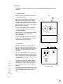
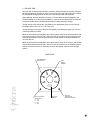
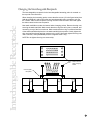
Harvester Operation and Service Manual
Before Setting Up Your Harvester . . . . . . . . . . . . . . . . . . . . . . . . . . . . . . . . . . . . . . . . . . . . . . . . . .3
Parts List . . . . . . . . . . . . . . . . . . . . . . . . . . . . . . . . . . . . . . . . . . . . . . . . . . . . . . . . . . . . . . . . . . . . .3
Requirements . . . . . . . . . . . . . . . . . . . . . . . . . . . . . . . . . . . . . . . . . . . . . . . . . . . . . . . . . . . . . . . . .3
Harvester Installation . . . . . . . . . . . . . . . . . . . . . . . . . . . . . . . . . . . . . . . . . . . . . . . . . . . . . . . . . . .4
Wash Installation . . . . . . . . . . . . . . . . . . . . . . . . . . . . . . . . . . . . . . . . . . . . . . . . . . . . . . . . . . . . . .5
Vacuum Installation . . . . . . . . . . . . . . . . . . . . . . . . . . . . . . . . . . . . . . . . . . . . . . . . . . . . . . . . . . . .6
Operation . . . . . . . . . . . . . . . . . . . . . . . . . . . . . . . . . . . . . . . . . . . . . . . . . . . . . . . . . . . . . . . . . . . .8
Adjustments . . . . . . . . . . . . . . . . . . . . . . . . . . . . . . . . . . . . . . . . . . . . . . . . . . . . . . . . . . . . . . . . .10
Options . . . . . . . . . . . . . . . . . . . . . . . . . . . . . . . . . . . . . . . . . . . . . . . . . . . . . . . . . . . . . . . . . . . . .16
Interchangeable Receptacle . . . . . . . . . . . . . . . . . . . . . . . . . . . . . . . . . . . . . . . . . . . . . . . . . . . . . .21
Tubing . . . . . . . . . . . . . . . . . . . . . . . . . . . . . . . . . . . . . . . . . . . . . . . . . . . . . . . . . . . . . . . . . . . . . .22
General Maintenance . . . . . . . . . . . . . . . . . . . . . . . . . . . . . . . . . . . . . . . . . . . . . . . . . . . . . . . . . .23
Tips for Using Your Harvester . . . . . . . . . . . . . . . . . . . . . . . . . . . . . . . . . . . . . . . . . . . . . . . . . . . .24
Filter Paper . . . . . . . . . . . . . . . . . . . . . . . . . . . . . . . . . . . . . . . . . . . . . . . . . . . . . . . . . . . . . . . . . .25
Warranty Information . . . . . . . . . . . . . . . . . . . . . . . . . . . . . . . . . . . . . . . . . . . . . . . . . . . . . . . . . .26
1
Thank You
Brandel would like to thank you for your purchase.
Your new Harvester is the product of more than 25 years of ongoing refinement, designed
to provide you with many years of use and satisfaction with a minimum of maintenance.
We are confident that you will find your Harvester to be one of the best pieces of equipment available today, and for years to come.
If you have any questions or suggestions, now or in the future, please do not hesitate to
contact us.
About this Manual
Copies of this manual are posted on the Brandel web site in Adobe Acrobat® (pdf) format.
If you misplace your original or find the digital form more convenient, please feel free to
download a copy and save it on your computer for future onscreen reference or printing.
We strongly encourage you to read this manual carefully as you unpack and assemble your Harvester. The time you spend doing so will help you to better understand its
workings and capabilities, and will minimize the amount of time spent on installation.
Please refer to the General Maintenance section on page 23 for suggestions on keeping
your Harvester in optimal condition.
On page 24 you will find Helpful Tips and answers to frequently asked questions.
BRANDEL, Inc.
8561 Atlas Drive
Gaithersburg, MD 20877
E-mail: [email protected]
http://www.brandel.com
Telephone: 800-948-6506
Fax: 301-869-5570
The systems and products displayed in this manual are for illustration purposes only.
Due to technical advances, actual products may not be exactly as illustrated.
2
Before Setting Up Your Harvester
Remove all packing materials and inspect for shipping damage!
If there is any damage, please report the nature of the damage to your local branch of the
shipping company who delivered your Harvester. If necessary, contact Brandel for
replacement parts.
Connect handle into “on-off” valve on the bottom, right of harvester. This handle was
disconnected for shipping purposes.
Your Shipment Includes
1 each
1 each
1 each
1 each
1 each
1 each
1 each
1 each
1 each
1 box
1 piece
1 piece
1 each
1 pkg.
1 piece
1 piece
3 each
1 each
Harvester
Power Cord
4 litre Wash Bottle; CH-100
Test Tube Rack (if harvesting from test tubes); CH-111 (standard) or CH-112
4 litre Collection Reservoir; CH-300
Wash Pump; CH-600
Solenoid Bay; CH-200
Vacuum Gauge; CH-900
On-Off Valve; CH-450
Whatman Filter Paper
Wash Tubing (for wash bottle to wash pump), connected to Wash Bottle
Wash Tubing (for wash pump to solenoid), connected to Wash Pump
Flow Regulator Valve; CH-601
Flow Adjustment Wrenches
Vacuum Hose (for trap bottle to vacuum source),
Vacuum Hose (for trap bottle to on-off valve), connected to Collection Reservoir
3 amp Fuse
Operation and Service Manual
Additional items will be included if they were ordered with the Harvester.
Requirements For Use
• Standard electric wall outlet (110V or 220V depending on your region)
• Vacuum source (house) or vacuum pump. Vacuum source must be equivalent to 20” of
3 Hg. at 3.5 cf./min.
• Please Note: A faucet aspirator will not provide sufficient vacuum for the Harvester to
perform properly.
• Brandel offers a full line of vacuum pumps which are ideal for use with your Harvester.
Please contact Brandel for ordering information, or visit our Web site to learn more.
BRANDEL, Inc.
8561 Atlas Drive
Gaithersburg, MD 20877
Telephone: 800-948-6506
Fax: 301-869-5570
E-mail: [email protected]
http://www.brandel.com
3
Installing Your Harvester
Please Note: The power switch, located on the side of the solenoid box, must be turned on
in order for the Harvester to be activated. Brandel strongly suggests that this switch be
turned off at the end of each day or harvesting session. Turning this switch off will remove
voltage from all components.
In the event of a power surge, or if the power switch is inoperative, replace the fuse (extra
3 amp fuses have been supplied) which is located next to the power switch on the solenoid box.
1. Electrical Installation
Connect the male plug from the harvesting probe switch to the matching outlet on the
back of the solenoid chassis box.
Plug the female end of the Harvester power cord into the EC 320 connector located on the
back of the solenoid, plug the male end of the cord into a standard wall outlet (110V or
220V depending on your region). Depressing the wash switch on the right side of the harvesting probe should cause a clicking sound from the solenoid. Plug the cord from the
wash pump into the remaining outlet on the back of the solenoid chassis box.
SIDE
BACK
110V AC
For Wash Pump
Installation
Fuse
Power Switch
Plug For
Harvesting Probe
IEC 320 INLET
For Power Cable
110V SOLENOID CHASSIS BOX
4
2. Wash Installation
Connect the tubing from the wash media bottle to the open inlet connector on the wash
pump.
Confirm that the tubing from the outlet connector of the wash pump to the inlet (open) connector on the solenoid is in place. This tubing was connected to the wash pump prior to
shipment.
Fill the wash media bottle with the desired buffer. With the wash pump electrically
unplugged but with all tubing connected, elevate the wash bottle above the level of the
wash media pump. Depress the wash switch on the harvesting probe. Allow buffer solution
to flow through the wash pump until all air is removed from the pump. Outlet tubing from
the wash pump will begin to fill with wash media. Plug the wash pump electrical cord into
the back of the solenoid. Finally, place the wash media bottle at the desired level (above
the wash pump).
CAUTIONS
•
•
•
•
Do not run pump dry.
Do not tighten top on wash media bottle.
Do not place wash media bottle lower than the wash pump.
If it becomes necessary at some point to dislodge air bubbles from inside the wash
pump, re-prime the wash pump using the same procedure described above.
Installation
WASH
PUMP
WASH
BOTTLE
FLOW REGULATOR VALVE
(Optional)
SOLENOID
5
3. Vacuum Installation
This section only applies to machines without the programmable controller (on page 15).
The on-off valve, located on the front, right corner of the base plate, eliminates the need
for turning on/off your vacuum after each harvesting procedure. Prior to harvesting, the
vacuum hose, labeled “connect to on/off valve” on the collection reservoir should have
been connected to the open plastic connector of the on-off valve. Turning the handle to
the “Harvest” position (Fig. A) will open your vacuum to the Harvester. Turning the handle
completely inward to the “Purge” position (Fig. B) will aspirate your buffer solution back
towards the wash manifold and prevent any drippage from the harvesting probe when the
Harvester is not in use. The “off” position (middle position of valve) will completely shutdown the vacuum to the Harvester and allow for filter paper removal.
A. COMMON COLLECTION OF FILTRATE
Install the tubing on the collection reservoir (labeled “connect to vacuum source”) to a
house vacuum line (vacuum source must be equivalent to 20” of 3 Hg. at 3.5 cf./min.) or
the vacuum pump. Install the tubing (labeled “connect to on-off valve”) to the open 3/8”
hose adapter on the on-off valve.
PU
R
G
E
PU
R
G
E
Brandel strongly suggests placing a second collection reservoir in the
line going to your vacuum source to prevent water vapor from entering
your system.
OFF
OFF
Installation
ST
VE
AR
H
ST
VE
AR
H
A
B
ON/OFF VALVE
6
B. INDIVIDUAL COLLECTION OF FILTRATE
When using the individual collection box, remove the four wing nuts from the interchangeable block(s) (plastic hose adapter is located in the middle of the block) located underneath the top plate on the back, right corner and replace with the interchangeable
block(s),which is tubed to the individual collection box.
Make certain that the dowel pins located on the interchangeable block(s) fit into the corresponding hole of the matching interchangeable block(s).
Remove the vacuum hose which is connected to your on-off vacuum valve on the base of
the Harvester. Place the vacuum hose coming from the individual collection box, onto the
same on-off valve connector.
Installation
When using your individual collection box, the “BRANDEL” engraving on the lid of the individual collection box should face towards the front of the Harvester. The row closest to the
“front” of the individual collection box corresponds with the first row on your filter block.
When finished collecting your individual filtrates, open the three-way valve, (located on the
vacuum hose coming from the individual collection box), to release the vacuum from
inside of the individual collection box.
7
Operation of Your Harvester
1. Microtitre Tray & Test Tube Rack Holder
The tray on the front of the harvester is for securing your micro-titre plate or test tube rack
in place while harvesting. To put the tray into its functioning position, lift the front of the tray
until the dowel pins are aligned with the grooves in the tray holders (which hold the tray on
the top plate). Push the tray straight back until the dowel pins enter and clear the groove,
then push down softly until the plate stops.
To disengage the tray, lift the front of the tray until you can see the dowel pins in the center
of the groove. Pull the tray forward, clearing the dowel pins from inside the holders.
Continue to pull the tray forward until it comes to a stop, then lower the front of the tray.
The tray should now be hanging down and out of the way, in front of the Harvester.
2. Proper Aspiration
Make certain that the aspiration needles in the harvesting probe are not touching the bottom of the wells when aspirating. Hold the probe slightly above the bottom of the wells in
order to prevent the bottom of the aspiration needles from sealing against the bottom of
the wells. If the aspiration needles are sealing, individual wells may overflow.
Make certain that with a strip of filter paper inside the filtering block, your vacuum gauge is
reading a minimum of 18” Hg. while aspirating. A vacuum reading of less than 18” Hg.
may lead to poor aspiration, and individual wells overflowing.
When the Harvester is not in use, keep the filter block closed, but not latched, to prevent
unnecessary strain on the o-rings.
When using a microtitre plate configuration, make certain that the two-way valve on the
black wash pump has been adjusted to prevent excessive delivery into each individual
well.
Operation
Make certain that the handle on the on-off vacuum valve is fully turned to the “HARVEST”
position in order to ensure proper aspiration from the harvesting probe.
If you are using the tray on the front of the Harvester, and are harvesting (especially from
test tubes), make certain that while the harvesting probe is held off the bottom of the wells
that the tubing is not being crimped on the back side of the harvesting probe. Holding the
probe near the latches on the filter block (at the back edge of the tray) and very high off
the bottom of the wells (5” or more) may cause a decrease in aspiration.
8
3. Proper Delivery
Make certain that the handle on the on-off vacuum valve is fully turned to the “HARVEST”
position and secured in place to allow for delivery of buffer to the harvesting probe. If the handle is not turned to this position your buffer solution will go directly into your collection flask.
Make certain that the wash pump has been completely primed (see page 5).
If you are using a two-way valve on the black wash pump make certain that the valve is
not closed so far as to prevent an adequate amount of delivery into each individual well.
4. Securing the Harvesting Probe After Harvesting
A. SECURING A TEST TUBE PROBE
Two metal probe holders are individually packed with machines using a test tube harvesting probe. The screws for mounting these probes have already been placed in the appropriate holes on the back side of the Harvester, on the top plate. Attach the probe holders
(“A” in the figure below) to the Harvester with these screws.
When not in use, the test tube harvesting probe should be inverted into the holders. Place
the probe onto the holders such that when facing the front of the Harvester, the wash
switch cap on the probe fits into the groove on the right side of the holder.
B. SECURING A MICROTITRE PROBE
Machines ordered with a microtitre probe will have their probe holder mounted on top of
the filter block (“B” in the figure below). WHen not in use, the microtitre probe should be
placed into this holder such that the needles are pointing downward and are going
through the opening on the holder.
NOTE: The on-off valve should be set to purge for a brief second prior to placing the
probe into its holder.
Operation
A - Test Tube Probe Holder
B - Microtitre Probe Holder
(24-Sample Filter Block Shown)
9
Making Adjustments to Your Harvester
1. Test Tube Probe Needle Tubing Length
The length of the Teflon tubing which comes through the ends of the stainless steel test
tube probe aspiration needles was pre-set at the factory. However, if an adjustment to the
amount of tubing protruding from these needles is required, follow the procedure below.
A. INCREASING THE EXPOSED LENGTH OF TUBING
Push down on the Teflon tube immediately above the chrome fitting which is securing the
specific piece of tubing being adjusted. Continue pushing down on the tubing until the
desired length is acquired.
B. DECREASING THE EXPOSED LENGTH OF TUBING
Press down on the chrome fitting which is securing the specific piece of tubing being
adjusted. While pressing down on the chrome fitting, raise the Teflon tube to the desired
height.
Make certain as not to allow the exposed length of any piece of Teflon tubing protruding
through the aspiration needles to become too long. If the Teflon tubing is set too long the
piece of tubing will touch the bottom of your test tube, preventing proper aspiration.
2. Microtitre Tray & Test Tube Rack Holder
The two white plastic pieces on the tray and test tube rack holder have been slotted to
allow adjustment of how tightly the plate/test tube rack is held in place while harvesting.
Adjustments
To adjust the fit on the tray/test tube rack, loosen the two screws on the two plastic pieces.
Slide the pieces in the necessary direction until the proper fit is obtained. Re-tighten the
two screws.
NOTE: Do not over-tighten the screws on the two plastic pieces.
10
3. Wash Fluid Pressure
On Harvesters working from micro-titre plates the flow regulator valve between the wash
pump and the solenoid has been pre-adjusted to prevent an overflow in the wells.
Harvesters working only from test tubes have been set to achieve the maximum flow possible. However, if a change in flow rate is desired follow the procedure below.
If a decrease in flow is desired (and the harvester is working from test tubes) substitute the
additional hose (supplied with the flow regulator valve) which was labeled and packed in
the accessory box, for the hose which is currently between the wash pump and the solenoid.
Obtain a minimum reading of 18” of Hg. on the Harvester vacuum gauge. Place the harvesting probe in the plate or test tubes and depress the switch.
Adjust the two-way valve such that the flow washes all wells sufficiently but does not overflow individual wells.
Caution: Do not turn the two-way valve so far as to allow only a drippage of wash fluid to
be delivered to any well.
Adjustments
OPEN - Maximum Wash Fluid Pressue
CLOSED - No Wash Fluid Pressue
VACUUM PUMP
FLOW REGULATOR VALVE
11
4. Individual Flow Adjustment for Each Well
Although this procedure is detailed below, it should never need to be done!
Please contact Brandel before attempting individual flow adjustment!
The flow of each channel has been adjusted such that all channels deliver an equal
amount of wash solution. Usually these channels never need to be adjusted. However, if
the system requires some further adjustment, adjust the fastest channel such that it delivers the same rate of wash solution as the slowest channel.
WHEN USING THE COLLECTION MANIFOLD...
1.Place the probes into individual test tubes or wells. Depress the wash switch on the
harvesting probe until the test tubes are approximately 3/4 full.
2.On the flow adjustment bar (secures tubing above harvesting probe) are individual set
screws that adjust the flow of each individual delivery needle. To decrease the flow, turn
the corresponding set screw in approximately 1/2 turn, (or less) if a very small change is
needed. An allen wrench is supplied.
3.Repeat first step.
WHEN USING THE INDIVIDUAL COLLECTION FILTRATE BOX...
Adjustments
1.Depress the wash switch on the harvesting probe and allow wash media to aspirate until
the collection tubes in the collection box are approximately 3/4 full.
2.On the flow adjustment bar (secures tubing above harvesting probe) are individual set
screws that adjust the flow of each individual delivery needle. To decrease the flow, turn
the corresponding set screw in approximately 1/2 turn, (or less) if a very small change is
needed. An allen wrench is supplied.
3.Repeat first step.
12
5. O-Ring Pressure Adjustment
Proper scoring is being obtained if all o-rings are making a uniform circular pattern on the
filter paper.
The amount of pressure applied by the “o-rings” was adjusted for proper pressure prior to
shipping. However, if a change in the amount of pressure is desired follow the procedure
stated on the following page.
Parallel
Correct
Adjustments
CORRECT
WRONG
WRONG
13
6. Adjusting Pressure on the Front Half of the Filter Block
Adjust the three (or four) latches on the front of the filter block. Turning the latches clockwise will increase the amount of pressure applied by the front half of the filter block.
Turning the latches counter-clockwise will decrease the amount of pressure.
Warning: Only turn the latches one full rotation at a time before re-testing the pressure
being applied to the front half of the filter block.
7. Adjusting Pressure on the Back Half of the Filter Block
Release the three (or four) latches on the front of the filter block and loosen the six “top
screws” on the top half of the filter block hinge.
Turning the “adjustment screws” clockwise will increase the amount of pressure being
applied by the back half of the filter block. Turning the “adjustment screws” counter-clockwise will decrease the amount of pressure being applied by the back half of the filter
block.
Warning: Only turn each “adjustment screw” 1/2 rotation before re-testing the pressure
being applied to the back half of the filter block.
Prior to re-testing the back pressure of the filter block make certain the six “top screws”
have been re-tightened.
Hinge Adjustment Blocks
Adjustment Screws
Adjustments
Latches
Front
Top Screws
Hinge
SIDE VIEW OF FILTER BLOCK
14
8. Aspiration
Caution: Release the three (or four) latches on the block when the Harvester is not in use
to prevent any “flattening” of the o-rings.
Release the latches on the filter block and raise the top half of the filter block. Place one
strip of filter paper over the metal screens on the bottom half of the filter block. The filter
paper should be wet to prevent leakage around the edges. Close the filter block, making
certain all o-rings are completely inside the strip of filter paper. Fasten the latches to the
strikes on the top half of the filter block. Turn on the vacuum source, or open on-off vacuum valve if vacuum source is already on. Check the vacuum gauge indication to make
certain a reading of 18” of Hg. or more is being obtained.
If the vacuum gauge does not read at least 18”
of Hg. place the harvesting probe into microtitre plates or test tubes (depending on type of
probe being used) and repeatedly depress
wash switch on probe until a reading of 18” of
Hg. is obtained.
If a reading of 18” of Hg. is still not obtained
make certain that all o-rings are “scoring” the
paper sufficiently and that all tubes in the
system are secured.
20
15
10
5
25
30
0
Hg
Adjustments
Please contact Brandel if these steps are
not sufficient to obtain proper vacuum, as
the problem may be an insufficient vacuum source.
VACUUM GUAGE
15
Optional Components for Your Harvester
1. Remote Programmable Controller
For detailed instructions on using the Remote Programmable Controller, (if ordered) please
consult the Remote Programmable Controller Manual.
To connect the remote programmable controller to your Harvester, first plug the Harvester
switch cable into the “Harvester Switch” jack on the back of the controller.
Next, plug the timer box into a standard wall outlet.
It is strongly recommended that the Harvester power cord be plugged into CH #2 and the
was pump be plugged into CH #1. Using these two outlets will enable the user to have the
manual wash available at any time.
2. Large-Capacity Reservoir with Auto-Drain
There are three main components that make up the auto-drain system.
1.Large-Capacity Collection Reservoir
2.Auto-Drain Controller
3.Auto-Drain Pump
Notice that on all the tubes attached to the reservoir are labels specifying where each
tubing connection should be made.
1.Connect the tubing labeled “Drain Reservoir” to the drain on the plexiglass reservoir.
2.Connect the tubing labeled “Connect to Drain Pump” the the auto-drain pump on the
horizontal fitting.
3.Connect the tubing labeled “Connect to Collection Reservoir” coming from the fitting on
the auto-drain box to the top of he collection reservoir.
4.Attach the tubing labeled “Connect to Vacuum Source” to a vacuum supply.
5.The tubing attached to the drain pump that has no label goes to your final drain
receptacle.
Options
Three electrical connections must also be made to the auto-drain box.
1.Connect the power cord to the auto-drain box
2.Connect the collection reservoir sensor to the auto-drain box.
3.Connect the auto-drain pump to the auto-drain controller
The included keys are to be used to switch the auto-drain box to either automatic or manual mode. In manual mode, the the collection reservoir can only be drained by depressing
the black button. When the collection reservoir is filled to the upper sensor, a red, flashing
light is activated and an audible alarm is sounded (if selected). In automatic mode, the
collection reservoir empties when filled to the top of the sensor. When harvesting in this
mode, it is critical that the drain tubing from the pump is placed in an emptying receptacle.
In either mode, the collection reservoir will empty only to the point of the bottom of the sensor. If more drainage is required, depress and continually hold the black manual drain button. Care must be taken so as not to completely empty the bottle and the pump as this will
necessitate a repriming of the pump.
16
3. Hot-Cold Collection Valve
The hot-cold wash valve is designed to provide the ability for separate collection of
radioactive and non-radioactive waste.
If the hot-cold wash valve was not originally ordered with the Harvester and installed by
Brandel, use the two extra holes located on the left side of the base plate of the Harvester
for mounting the hot-cold wash valve.
When using the hot-cold wash valve connect the vinyl tubes on the collection reservoir
bottles (labeled “connect to valve”) to the two remaining connectors on the bottom half of
the hot-cold wash valve. Connect the tube on the plastic “Y” (labeled “connect to vacuum
source”) to your vacuum source. Connect the two remaining tubes on the plastic “Y”
(labeled “connect to trap bottles”) to the collection bottles.
When using and disposing of non-radioactive waste turn the top half of the valve (using
the handle installed in the valve) in the direction of “cold” port. Turning the valve clockwise
(as far as possible) will allow for the use and disposal of radioactive waste into the “hot”
collection reservoir bottle.
To disassemble the hot-cold wash valve remove the two screws located on the bottom
side of the base plate which are securing the valve. Remove the four caphead screws on
the top half of the valve cover, counter-clockwise, thus removing the white colored valve
housing on the top of the valve. Remove the large cap screw inside the top half of the
valve such that both pieces will come apart. Use your fingers to remove the o-rings. Do
not use a sharp instrument to remove the o-rings.
To assemble, reverse the above process. When tightening the cap screw make certain
that the o-rings are sealing against the bottom of the top half of the valve. Check the turning motion for ease of movement.
Harvester
HOT
Options
'Y' Connector
Collection
Bottles
HO
T
D
L
CO
Vacuum Source
Hot/Cold
Valve
On/Off
Valve
COLD
17
4. Wash Timer
The wash timer assures that the same volume of wash solution is delivered to your wells
each time.
A. INSTALLATION
Place the wash timer next to the Harvester in
a convenient location.
TOP
Remove the male plug from the end of the
cord that is marked “TO SWITCH.” When
using the wash timer, place this male plug into
the back of the solenoid box on the back of
the Harvester. This will allow the timer to effectively operate the Harvester.
MANUAL
Plug the female plug marked “TO SWITCH”
into the male plug coming from the probe
cord of the Harvester.
OFF
AUTO
Plug the power cord of the Harvester into the
back of the wash timer plug marked
“TO HARVESTER.”
Plug the power cord of the timer marked “TO
110VAC” into a standard wall outlet (110V or
220V depending on your region).
B. OPERATION
Manual mode allows the operator to determine the amount of delivered wash solution
each time. The timer does not need to be disconnected from the Harvester for manual
operation.
Options
Automatic mode allows delivery of an identical amount of wash solution to all wells each
time. In Automatic mode, the delivery amount
can be adjusted by turning the knob on top of
the wash timer.
BACK
TO HARVESTER
TO SWITCH
TO 110V AC
To engage the wash timer, position the harvesting probe into the wells and hold down
the switch on the probe. Wash delivery will
automatically discontinue at the time interval
selected.
If the delivery switch is released prior the end
of the desired time cycle, delivery will discontinue immediately and the timer will reset
itself.
110V WASH TIMER
18
C. DELIVERY TIME
The timer has an almost infinite amount of settings, which will allow for a greater time period than the Harvester would ever need. For the purposes of this manual we only consider
the reasonable settings (amount of time) that could be used with the Harvester.
Upon shipping, the timer was set to run from 1-10 seconds and can be adjusted to the
preferred setting by turning the dial. However, if a period of time longer than ten seconds
is desired, please refer to the table shown below to obtain the proper setting.
Turning the left screw adjusts the Time Selector: this adjustment gives you four choices
that begin with times of: 0.5 or 1.0 or 2.0 or 10.0
Turning the right screw adjusts the Time Unit Display: this adjustment gives you a choice
of either seconds or minutes
When the time selector is adjusted to show the numbers in the far left column and the dial
is set at the number on the second column from the left, and the time unit display is set to
seconds, the amount of time (in seconds) the timer will operate is shown in the third column from the left.
When the time selector is adjusted to show the numbers in the far left column, and the dial
is set at the number on the second column from the left, and the time unit display is set to
minutes, the amount of time (in seconds) the timer will operate is shown in the far right
column.
TIMER FACE
Time Adjustment
Selector Knob
TIme
Selector
Windows
0
Options
5
Time Incremental
Selector Knob
0 – 0.2
0 – 1.0
0 – 2.0
0 – 10.0
3
4
1
2
Time Unit
Display
Time Unit
Selector Knob
(Seconds / Minutes)
19
5. Multi-Wash Systems
(for additional washes)
A complete wash system (if ordered) consists of:
1 each Wash Pump (optional)
1 each Wash Media Bottle
1 each Multi-Wash Table with Switch
1 each Wash Trough (mounted onto multi-wash table)
1 each Solenoid (mounted onto multi-wash table)
1 each 2-Way Flow Regulator Valve
1 each Necessary Tubing
Only part of the system may have been ordered with your Harvester. All instructions should
be modified accordingly.
A. CONNECTIONS AND INSTALLATION
Options
1.Connect the tubing from the multi-wash buffer bottle, labeled “connect to multi-wash
pump,” to the wash pump.
2.Connect the tubing labeled “connect to multi-wash solenoid” to the white fitting of the
solenoid on the multi-wash table.
3.Prime the multi-wash pump in the same manner as priming the wash pump for the harvester
(see page 3).
4.Place the multi-wash table near the Harvester in such a manner that the wash trough is
close to the front edge of the Harvester.
5.The flow regulator valve has already been pre-set. If a change in flow is desired turn the
handle on the flow regulator valve. (Turning the handle parallel to the valve increases the
flow, turning the handle perpendicular decreases the flow).
6.Plug the multi-wash pump plug into the back of the multi-wash solenoid.
7.Plug the multi-wash switch (located on the multi-wash table) into the back of the
multi-wash solenoid.
8.Plug the multi-wash solenoid into a standard wall outlet (110V or 220V depending on
your region).
The wash is fed into the trough by the depression of its corresponding switch located on
the multi-wash table. (If a wash pump was purchased with the multi-wash system, the twoway valve on the tubing from the wash pump can be adjusted to regulate the rate of flow
into the wash trough). With vacuum pressure applied and after filling the wash trough,
place the harvesting probe into the wash trough. The harvesting probe will aspirate the
additional wash fluid from the trough onto the filter paper. Additional washings may be
accomplished by repeating this procedure.
20
Changing the Interchangeable Receptacle
The interchangeable receptacle for the interchangeable harvesting probe is mounted on
the top side of the filter block.
Interchangeable Receptacle
When changing the harvesting probe, remove the allen screws (‘A’ in the figure below) that
hold the receptacle in place. Mount the new interchangeable probe receptacle such the
the “FRONT” label on the receptacle is facing the front of the Harvester. Insert and tighten
the allen screws into the new receptacle.
New wash manifolds must also be inserted when changing probes. Remove the wing nuts
securing the wash manifolds. Make certain that the o-rings are still in place, centered, and
not resting on top of the four metal nuts. Make certain that the o-ring is outside all needles
of the wash manifold and place the new wash manifold(s) into position. Gently tighten the
wing nuts until they begin applying pressure to the o-ring. Alternately tighten the wing nuts
until a sufficient, evenly distributed pressure is applied to the o-ring.
NOTE: Do dot tighten the wing nuts excessively.
A - Remove Screws
When Changing
Probes
Interchangable
Receptacle
21
Tubing for 12-Sample Harvesters
Interchangeable Receptacle (Optional)
2
1
2
1
2
3
4
5
3
6
4
7
5
5
8
6
6
9
7
10
9
8
9
8
11
10
11
11
12
12
12
Tubing
1
3
4
7
10
22
General Maintenance
Your Brandel Harvester has been designed for relatively maintenance free service.
However, certain steps should be taken to provide optimal service from your Harvester.
The steps detailed below will not only keep your Harvester aesthetically clean, but also
provide for uniform delivery and aspiration – even after years of use.
After shipment, and/or continued use of the Harvester the white plastic permanent ties
binding together the clear plastic tubing may need to be tightened. However, caution
should be exercised so as not to pinch shut any tubes. Normally, pushing down on the
square part (head) of the plastic permanent tie for one or two notches is sufficient to
secure the tubes into a firmly held bundle.
All outside lucite parts can be cleaned with alcohol, Windex or any other cleaning agent of
your choice which is not abrasive or a solvent to lucite.
After a few hours of occasional use or continued use over the course of a day the tubing
should be rinsed out with deionized water or a solution of 30% alcohol. After a period of
time a chemical solution can also be used to prevent or eliminate any counts from remaining inside the tubing.
A soft bristled brush (such as a toothbrush) may be used with water or alcohol to clean the
stainless steel filter screens.
After prolonged use over years you may wish Brandel to provide replacement tubing,
o-rings or screens.
Brandel can provide tubing in coils (you re-tube the lines to be changed) or all tubes coming to and going from harvesting probe pre-cut with a new wash manifold (for your convenience), labeled and ready to be installed. This tubing can also be pre-cut for your collection manifold (new collection manifold, for your convenience), labeled and ready to be
installed.
Maintenance
All o-rings are supplied with epoxy for replacement.
Your Harvester’s stainless steel filter screens have been pressed into your filter block.
Brandel will supply the replacement screens for you to fit back into place. Simply remove
the old screen; pry out with a suitable object, and place the new screens into place.
23
Tips for Using Your Harvester
1. Proper Aspiration
Make certain that the aspiration needles in the harvesting probe are not sitting on the bottom of the wells when aspirating. Hold the probe slightly above the bottom of the wells in
order to prevent the bottom of the aspiration needles from sealing against the bottom of
the wells. If the aspiration needles of the harvesting probe are sealing against the bottom
of the wells, certain wells may overflow.
Make certain that with a strip of filter paper inside the filtering block your vacuum gauge is
reading a minimum of 18” Hg. while aspirating. A vacuum reading of less than 18” Hg.
may lead to poor aspiration, and individual wells overflowing.
While not using the Harvester, the filter block should be closed but not latched, to prevent
unnecessary strain on the o-rings.
Make certain that if you are using a microtitre plate configuration you have adjusted the
two way valve on the black wash pump to prevent an excessive amount of delivery into
each individual well.
Make certain that the handle on the on-off vacuum valve is fully turned to the “HARVEST”
position in order to ensure proper aspiration from the harvesting probe.
If you are using the tray on the front of the Harvester, and are harvesting (especially from
test tubes), make certain that while the harvesting probe is held off the bottom of the wells
that the tubing is not being crimped on the back side of the harvesting probe. Holding the
probe near the latches on the filter block (in other words, at the back edge of the tray) and
very high off the bottom of the wells (5” or more) may cause a decrease in the aspiration.
2. Proper Delivery
Make certain that the handle on the on-off vacuum valve is fully turned to the “HARVEST”
position and secured in place to allow for delivery to the harvesting probe. If the handle is
not fully turned to the “HARVEST” position, the buffer solution will go directly into your collection flask.
Make certain that the wash pump has been completely primed.
Make certain that if you are using a two-way valve on the black wash pump not to have the
valve closed so far as to prevent an adequate amount of delivery into each individual well.
3. After Harvesting
Prior to placing the two metal rods of the harvesting probe into the corresponding holes on
the top half of the filter block, pull back on the tygon tubing which is above the filter block.
Pulling this tubing toward the back of the Harvester will allow the harvesting probe rests
(two metal rods) to fit better and remain seated into the filter block.
24
Filter Paper for All Harvesters
Filter Paper
Harvester
Reeves Angel 934H
Whatman GF/B
Whatman GF/C
For Standard Format Harvesters without Deposit/Dispensing Systems
12-sample Harvesters
FP-12
FP-101
24-sample Harvesters
FP-24
FP-100
30-sample Harvesters
FP-30
FP-130
36-sample Harvesters
FP-36
FP-136
48-sample Harvesters
FP-48
FP-105
96-sample Harvesters
FPD-96
FPD-196
FP-201
FP-200
FP-230
FP-236
FP-205
FPD-296
For Standard Format Harvesters with Deposit/Dispensing Systems
12-sample Harvesters
FPD-12
24-sample Harvesters
FPD-24
30-sample Harvesters
FPD-30
36-sample Harvesters
FPD-36
48-sample Harvesters
FPD-48
96-sample Harvesters
FPD-96
FPD-101
FPD-100
FPD-130
FPD-136
FPD-105
FPD-19
FPD-201
FPD-200
FPD-230
FPD-236
FPD-205
FPD-296
For All Counter-Compatible Harvesters
12-sample, 20ml vials
18-sample, 5 or 7ml vials
24-sample, 20ml vials
30-sample, 20ml vials
36-sample, 5 or 7ml vials
36-sample, 20ml vials
48-sample, 5 or 7ml vials
48-sample, 20ml vials
96-sample, 5 or 7ml vials
96-sample, 20ml vials
FP*-112
FP*-118
FP*-124
FP*-130
FP*-136
FP*-136L
FP*-148
FP*-148L
FP*-196
FP*-196L
FP*-212
FP*-218
FP*-224
FP*-230
FP*-236
FP*-236
FP*-248
FP*-248L
FP*-296
FP*-296L
FP*R-124
FP*R-105
FP*R-196
FPX*R-196
FP*R-224
FP*R-205
FP*R-296
FPX*R-29
FP*-12
FP*-18
FP*-24
FP*-30
FP*-36
FP*-36L
FP*-48
FP*-48L
FP*-96
FP*-96L
For All Direct Radioactive Reader Compatibles
24-sample 4x6 format
FP*R-24
48-sample 4x12 format
FP*R-05
96-sample 6x16 format
FP*R-96
96-sample microtitre
FPX*R-96
* Please enter the letter that corresponds to your counter or direct reader: B Beckman L LKB P Packard
Others filters available on request
BRANDEL, Inc.
8561 Atlas Drive
Gaithersburg, MD 20850
Telephone: 301-948-6506
Fax: 301-869-5570
E-mail: [email protected]
http://www.brandel.com
25
Warranty
Biomedical Research and Development Laboratory, Inc. (BRANDEL) guarantees for a
period of one year from the original date of shipment, all parts manufactured by it to be
free from defects in workmanship and materials. All defective parts will be replaced without charge for parts or labor. BRANDEL will not accept expense or labor incident to the
replacement of any part outside of its factory.
Warning
The purchaser assumes all risks in the use and handling of items sold by BRANDEL.
BRANDEL is not liable for loss or damage resulting from use or misuse of the products
sold by BRANDEL.
26