1
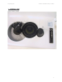
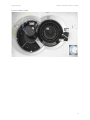
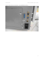
Hospitex Diagnostics
EOS Bravo and EOS Bravo Plus Service Manual
EOS Bravo and EOS Bravo Plus
LICG895 – LICG892 – LICG890
PRELIMINARY
H
H
Service Manual
HOSPITEX DIAGNOSTICS
Via Provinciale Lucchese 145 - 50019
Sesto Fiorentino (Florence ) Italy
Tel. +39 055 374083 Fax + 39 055 374084
e-mail : [email protected]
web : http://www.hospitex.com
1
Hospitex Diagnostics
EOS Bravo and EOS Bravo Plus Service Manual
INDEX
1. GENERAL VIEW
2. SERVICE MENU
3. ASSEMBLY AND ADJUSTMENT
4. ELECTRONIC AND MENCHANICAL DESCRIPTION
2
Hospitex Diagnostics
EOS Bravo and EOS Bravo Plus Service Manual
1 - GENERAL VIEW
Figure 1: Mono Cuvette
3
Hospitex Diagnostics
EOS Bravo and EOS Bravo Plus Service Manual
Figure 2: Double Cuvette
4
Hospitex Diagnostics
EOS Bravo and EOS Bravo Plus Service Manual
Figure 3: External Devices connections ( mono and double cuvette )
5
Hospitex Diagnostics
EOS Bravo and EOS Bravo Plus Service Manual
2 - SERVICE MENU
MAIN MENU’ > F5 SERVICE
F1 : WORKING PARAMETERS
F2 : MANUAL AND AUTOMATIC WASHINGS, AUTOZERO
F3 : MECHANICAL AND FUNCTIONAL TESTS
F4 : SYSTEM PARAMETERS ( ONLY FOR SERVICE )
F5 : LABORATORY HEADING AND OPERATOR’S NAME
6
Hospitex Diagnostics
EOS Bravo and EOS Bravo Plus Service Manual
MAIN MENU’ > F5 SERVICE > F1 USER PARAMETERS
WASHING STEPS
ASPIRATION STEPS
OUTER PLATE TEMP.
CUVETTE TEMP.
ENABLE REACTION SHAKE
PRE-HEATING DUTY-CYCLE
PRINTER MODE
AUTOMATIC DATE
: Peristaltic pump’s steps relative to the first and the second
phase of aspiration, used to wash the cuvette with liquid and air
: Peristaltic pump’s steps used to aspirate the remain of the
liquid from the cuvette
: Parameter to modify the temperature of the plate which holds
the reaction segments
: Parameter to modify the temperature of the cuvette
: Parameter to enable the function of shake of the plate which
holds the reaction segments
( 0 = NO, 1 = YES )
: Parameter relative to the power impulse relative to the
resistance that is situated around the heating reel
: Parameter relative to the printing
0 : 0 = ALL THE PRINTING ARE MADE ON THE INTERNAL
PRINTER
1 : 0 = THE PRINTINGS OF THE SESSION ARE MADE ON
THE INTERNAL PRINTER AND THE PRINTINGS OF THE
REFERTS ARE MADE ON THE EXTERNAL PRINTER
1 : 1 = ALL THE PRINTING ARE MADE ON THE EXTERNAL
PRINTER
: Parameter relative to the date and time from the internal PC
0 = NO
1 = ONLY DATE
2 = DATE + HOUR
7
Hospitex Diagnostics
EOS Bravo and EOS Bravo Plus Service Manual
MAIN MENU’ > F5 SERVICE > F2 WASHINGS
F1 WASH POSITION
: Used to select the number of the hole used for the washings
F2 WASHES
: The instrument executes a number of XX washings in automatic
F3 TUBES WASH
: The instrument executes a washing cycle of the sampling circuit
F4 CUVETTE WASH
: The instrument executes a washing cycle of the aspiration circuit
F5 AUTOZERO
: The instrument executes the autozero of all filters on board to the
filter wheel
8
Hospitex Diagnostics
EOS Bravo and EOS Bravo Plus Service Manual
MAIN MENU’ > F5 SERVICE > F2 WASHINGS > WASH POSITION
F1 WASH POSITION
: Used to select the number of hole used for the wash ( on the example, the
First hole on the first reaction segment )
9
Hospitex Diagnostics
EOS Bravo and EOS Bravo Plus Service Manual
MAIN MENU’ > F5 SERVICE > F2 WASHINGS > F2 WASHES
F2 WASHES
: Used to determinate the number of XX complete washes of the hydraulic
circuit SAMPLING/ASPIRATION ( min 1, max 99 ).
This is useful when we want to wash the hydraulic circuit very accurately but
We don’t want remain in front of the instrument.
10
Hospitex Diagnostics
EOS Bravo and EOS Bravo Plus Service Manual
MAIN MENU’ > F5 SERVICE > F2 WASHINGS > F5 AUTOZERO ( MONOCUVETTE )
F5 AUTOZERO
: Used to execute an autozero of the complete filter wheel.
In case that during the autozero there are no variations respect the previous
Values the cycle will be terminated without any signal.
11
Hospitex Diagnostics
EOS Bravo and EOS Bravo Plus Service Manual
MAIN MENU’ > F5 SERVICE > F2 WASHINGS > F5 AUTOZERO ( DOUBLECUVETTE )
F5 AUTOZERO
: Used to execute an autozero of the complete filter wheel.
In case that during the autozero there are no variations respect the previous
Values the cycle will be terminated without any signal.
12
Hospitex Diagnostics
EOS Bravo and EOS Bravo Plus Service Manual
MAIN MENU’ > F5 SERVICE > F2 WASHINGS > F5 AUTOZERO
F5 AUTOZERO
: Example of autozero with a variation in the reading.
A variation of +/- 5% is shoved with the visualization of the following voices:
ESC : ABORT – Cancels the session
F1 : REPEAT - Repeat the session of autozero
ELSE : ACCEPT – Pressing any key except the key “ ESC “
or “ F1” we accept the new value visualized
EVERY TIME THE AUTOZERO GETS BLOCKED, PRESS F1 TO
RESTART THE PROCEDURE
13
Hospitex Diagnostics
EOS Bravo and EOS Bravo Plus Service Manual
MAIN MENU’ > F5 SERVICE > F2 WASHINGS > F5 AUTOZERO
F5 AUTOZERO
: Example of autozero with a problem.
In this particular case we have the lamp which is not functioning.
This can be noted since the values of all filters are very similar if not equal
to the FILTER 0 = OFFSET
14
Hospitex Diagnostics
EOS Bravo and EOS Bravo Plus Service Manual
MAIN MENU’ > F5 SERVICE > F3 DIAGNOSTICS
F1 READING TEST
: Used to execute the reading tests in mV or to execute the regulation
of the offset and the gain
F2 O.D. TEST
: Used to execute readings in absorbance
F3 HARDWARE TEST
: Used to execute tests of MECHANICAL/ELECTRONICAL functionality
F4 PROCEDURE TEST
: Execute a complete test divided in single operation
F5
: Reserved key
15
Hospitex Diagnostics
EOS Bravo and EOS Bravo Plus Service Manual
MAIN MENU’ > F5 SERVICE > F3 DIAGNOSTICS > F1 READING TEST ( MONOCUVETTE )
F1 READING TEST
: Remove the aspiration needle and put it in a holder with distillated
water.
Press F3 ASPIRATE to aspirate.
After you have aspirate water, select the filter 1 = 340 nm.
You get visualized the reading of the filter in mV and in digit.
Using the trimmer of the gain we can increase or decrease the value
of the reading.
Act on the gain trimmer to have a reading 1300 mV.
You should keep in mind, that once you act on the trimmer of the
gain to modify the reading of all the filters on board to the filters
wheel.
To execute the regulation of the offset select the Filter 0 = NULL
and act on the relative trimmer to have a reading > 1 mV.
Once the regulation of the gain and the offset is done, it’s necessary
To execute an autozero to be able to memorize the new values.
THE OPERATIVE RANGE FOR EVERY SINGLE FILTER IS 500 mV ÷ 1800 mV
16
Hospitex Diagnostics
EOS Bravo and EOS Bravo Plus Service Manual
MAIN MENU’ > F5 SERVICE > F3 DIAGNOSTICS > F1 READING TEST ( DOUBLECUVETTE )
F1 READING TEST
: Remove the aspiration needle and put it in a holder with distillated
water.
Press F3 ASPIRATE to aspirate.
After you have aspirate water select the channel that you want
adjust ( example F1 CUVETTE1 ) and select the filter 1 = 340 nm.
You get visualized the reading of the filter in mV and in digit.
Using the trimmer of the gain we can increase or decrease the value
of the reading.
Act on the gain trimmer to have a reading 1300 mV.
You should keep in mind, that once you act on the trimmer of the
gain to modify the reading of all the filters on board to the filters
wheel.
To execute the regulation of the offset select the Filter 0 = NULL
and act on the relative trimmer to have a reading > 1 mV.
Once the regulation of the gain and the offset is done, it’s necessary
To execute an autozero to be able to memorize the new values.
THE OPERATIVE RANGE FOR EVERY SINGLE FILTER IS 500 mV ÷ 1800 mV
17
Hospitex Diagnostics
EOS Bravo and EOS Bravo Plus Service Manual
MAIN MENU’ > F5 SERVICE > F3 DIAGNOSTICS > F3 HARDWARE TEST
F1 MOTOR ZERO
: Used to execute the home position of the motor under examination
F2 MOTOR FWD
: Used to move in the clock sense the motor under examination
F3 MOTOR BWD
: Used to move in the anticlock sense the motor under examination
F4 VALVE ON/OFF
: Used to verify the functionality of the electrovalve situated on the
diluter
Used to verify the functionality of the two pumps in the double
cuvette
F5 DISPLAY INP.
: The command F5 active the continues visualisation of the inputs
18
Hospitex Diagnostics
EOS Bravo and EOS Bravo Plus Service Manual
MAIN MENU’ > F5 SERVICE > F3 DIAGNOSTICS > F3 HARDWARE TEST
LEGENDA
MOT
: Number relative to the motor in object
DESCRIPTION
: Description of the motor in object
ENAB
: Command to block the motor in object
( 0 = FREE / 1 = BLOCKED )
SPEED
: Speed of the motor in object
IX. STEPS
: X Steps to execute with the motor in object
LOG. POS.
: Position were we want put the motor in object
ABS. POS
: Real position , in steps, that the motor has taken
19
Hospitex Diagnostics
EOS Bravo and EOS Bravo Plus Service Manual
MAIN MENU’ > F5 SERVICE > F3 DIAGNOSTICS > F3 HARDWARE TEST
LOGICAL POSITION
INNER PLATE
: The logical position from 0 to 31 carries the relative cups under the relative
point of sampling.
The logical position from 32 to 63 carries the relative cups under the relative
point of sampling.
OUTER PLATE
: The logical position from 1 to 96 carries the relative holes of the reaction
segments under the aspiration needle.
The logical position from 101 to 196 carries the relative holes of the reaction
Segments under the point positioning of sampling arm.
The logical position from 1 to 189 carries the relative holes of the reaction
segments under the aspiration needle *
The logical position from 201 to 389 carries the external ring of the reaction
segments under the point positioning of sampling arm *
The logical position from 202 to 390 carries the internal ring of the reaction
segments under the point positioning of sampling arm *
FILTER SELECT
: The logical position corresponds to the number of the relative filter
PERISTALTIC PUMP
: NOT IN USE
DILUTER SYRINGE
: The logical position indicates 1 uL to dispense
REAGENT PLATE
: The logical position from 1 to 18 or from 1 to 27 carries the sampling arm
up to the relative bottles.
The logical position 41 sampling arm up to the inner plate internal ring.
The logical position 42 sampling arm up to the inner plate external ring.
The logical position 43 sampling arm up to the outer plate.
The logical position 43 sampling arm up to the outer plate internal ring.*
The logical position 44 sampling arm up to the outer plate external ring.*
The logical position 44 sampling arm up to the repose condition
SAMPLING NEEDLE
: the logical position 3 sampling needle down in the bottom of sample cups.
The logical position 4 sampling needle down in the hole of the reaction
segments.
The logical position 8 sampling needle down in the bottom of the reagents
bottle.
20
Hospitex Diagnostics
ASPIRATION NEEDLE
EOS Bravo and EOS Bravo Plus Service Manual
: the logical position 4 aspiration needle down in the bottom of the holes
of the reaction segments.
the logical position 4 aspiration needle 1 down in the bottom of the holes
of the reaction segments external ring.*
* ONLY FOR THE DOUBLE CUVETTE
21
Hospitex Diagnostics
EOS Bravo and EOS Bravo Plus Service Manual
MAIN MENU’ > F5 SERVICE > F3 DIAGNOSTICS > F3 HARDWARE TEST > F5 DISPLAY INPUTS
MOT.L.SW.
: Indicates the logical status of the home position sensor and the logical
status of the level sensor.
CH0
: Channel of the A/D CONVERTER for the outer plate temperature.
Visualizes the value of temperature in teen degrees.
CH1
: Channel of the A/D CONVERTER for the cuvette temperature.
Visualizes the value of temperature in teen degrees.
CH2
: Not in use
CH3
: Not in use
READING
: Not in use
R
: Indicates the state of the functioning of the heating circuit of the outer
plate.
P
: Indicates the state of the functioning of the heating circuit of the optical
group.
22
Hospitex Diagnostics
EOS Bravo and EOS Bravo Plus Service Manual
MAIN MENU’ > F5 SERVICE > F4 SYSTEM PARAMETERS > PRESS THREE TIMES DOT ( . )
23
Hospitex Diagnostics
EOS Bravo and EOS Bravo Plus Service Manual
F1 SELECT PARAM.
: Select the parameter
F2 NEXT PAGE
: Calls the next page
F3 PREVIOUS PAGE
: Calls the previous page
F4 PRINT PARAM.
: Prints the parameters to the selected page
F5 CHANGE SIGN
: Changes the sign of the selected parameter
NOTE
THE ACCES TO THE PAGES OF THE SYSTEM PARAMETERS IS SUGGESTED ONLY
FOR THE Hospitex Diagnostics PERSONNEL OR OTHER AUTHORISED PERSONNEL.
24
Hospitex Diagnostics
N°
EOS Bravo and EOS Bravo Plus Service Manual
MNEMONIC
DESCRIPTION
IP MOTOR
SAMPLE
PLATE
32+32
DEFAULT
VALUE
000
001
002
003
IPNPS0
IPNPS1
IPOFS0
IPOFS1
Inner plate n° position of external ring
Inner plate n° position of internal ring
Inner plate offset for external ring
Inner plate offset for internal ring
32
32
-20
22
007
008
009
OPOFS1
OPOFS0
OPOFAN
OP MOTOR
Outer plate2 ring offset sample needle side
Outer plate ring offset sample needle side
Outer plate offset aspiration needle side
-333
-332
23
014
FSOFFS
FS MOTOR
Filter selection offset
018
DSCONV
DS MOTOR
Diluter syringe conversion factor
021
022
023
SNOFFS
SNHOME
SNHIGH
024
SNBOTL
025
SNCUPS
026
SNTUB
027
SNDISP
028
SNWASH
029
SNBUBL
030
SNBOTL
SN MOTOR
Sample needle offset
Sample needle home position
Sample needle height before home, for
rotation over reagent bottles
Sample needle out of blot paper filter ( not
for rotation)
Sample needle for sampling on internal
plate: sample/STD cups
Sample needle for sampling on internal
plate: sample/STD tube
Sample needle for dispensation on outer
plate
Sample needle for wash tubes on outer
plate
Sample needle for R2/R3 and bubbles
dispense on outer plate
Sample needle on reagent bottles
034
035
036
037
038
039
ANOFFS1
ANOFFS2
ANHIGH
ANWSH1
ANWSH2
ANDOWN
AN MOTOR
Aspiration probe n°1 offset
Aspiration probe n°2 offset
Aspiration probe high position in home pos.
Aspiration probe wash step 1
Aspiration probe wash step 2
Aspiration probe sampling step for reading
0
0
25
160
170
225
043
044
045
046
047
PMWSH1
PMWSH2
PMASP1
PMASP2
PMPMOD
PUMP MOTOR
Peristaltic pump wash step 1
Peristaltic pump wash step 2
Peristaltic pump aspiration step 3 cuvette 1
Peristaltic pump aspiration step 3 cuvette 2
Peristaltic pump mode
650
250
550
550
0
049
050
RPBOT6
RPBOT9
RP MOTOR
Rp motor position of bottle n°1 with rack 6
Rp motor position of bottle n°1 with rack 9
240
245
NOTE
Only for double cuvette
0
30086
(step*10ml)
0
0
15
50
190
363
243
243
270
370
Only for double cuvette
0 = Steps
75 = msec (only for double cuv. )
25
Hospitex Diagnostics
EOS Bravo and EOS Bravo Plus Service Manual
051
052
053
054
055
056
057
058
059
RPSTEP
RPOFFR
RPNULL
RP_IP0
RP_IP1
RP_OP0
RPOFFP
RP_OP1
RPWRAP
060
RGRACK
Rp motor steps between 2 bottles rack 6
Rp motor offset on reagent bottles
Rp motor idle position
Rp motor inner plate external ring
Rp motor inner plate internal ring
Rp motor outer plate dispensing position
Rp motor offset on inner/outer plates
Rp motor outer plate dispensing position
Else steps before reagent plate arm
mechanical stop
Reagent rack selection
30
-5
275
346
382
310
0
309
-10
062
IPVEL
MOTOR SPEED
Inner plate rotation speed
1160
064
065
OPVEL
OPVSHK
Outer plate rotation speed
Outer plate shake speed
540
700
067
FSVEL
Filters wheel rotation speed
640
069
070
071
072
073
PMVEL1
PMVEL2
DSVELU
DSVELD
DSVCAT
Peristaltic pump 1 rotation speed
Peristaltic pump 2 rotation speed
Diluter motor up speed
Diluter motor down speed
Not used
585
585
700
700
700
075
RPVEL
Reagent plate arm rotation speed
1400
077
078
079
SNVELU
SNVELD
ANVEL
Sampling needle up speed
Sampling needle down speed
Aspiration needle up/down speed
1160
1160
1160
082
083
RELEAS
SERMOD
VARIOUS
Current software release
Serial port mode
420
2
084
085
086
087
088
BAUDRT
CONPRN
EXEPRN
PDELIM
DATEEN
Host communication baud rate
Consolle printer
Execution printer
Execution printer results field delimiter
Automatic data & time from PC
57600
0
0
0
2
089
090
091
092
093
094
095
096
DISPLV
KEYB
FDELIM
OPTEMP
CVTEMP
RS2PWM
MAXPT2
RDEADV
Not used
Keyboard automatic setting
Not used
Outer plate setting temperature
Cuvette setting temperature
Sample needle pre-heating duty cycle
Peltier element maximum power
Reaction bottle dead volume in microliters
0
1
44
420
380
15
70
2000
098
OPPATH
Optical path selection
7
099
100
101
AUTOWL
OPSHAK
OPHOME
0
0
0
102
103
CATGAP
CATPAU
Not used
Outer plate shake enable
Outer Plate Home position check during the
execution run
Not used
Not used
18
18 reagents or 27 reagents
Only for double cuvette
0=Host, 1=Remote,
consolle
2=Graph
0=Int., 1=Loc. ext
0=Int., 1=Loc. ext
0=No, 1=Enable date from PC,
2=Enable Date&Time
0=Ita, 1=US, 2=Fra
°Cx10
°Cx10
Helma cuvette = 10
I.S.E. cuvette = 7
0 = NO, 1 = YES
0 = NO, 1 = YES
0
0
26
Hospitex Diagnostics
104
105
106
107
108
109
110
111
112
113
114
RPRVOL
CUPVOL
WSHTUB
CUPTYP
MCYCLE
SCHMOD
WSHSMP
TIMOUT
ERTOUT
BUZMOD
LEVREA
115
LEVMOD
116
117
LEVSMP
KLEVR6
118
119
LEVERR
KLEVR9
120
121
122
123
124
125
126
127
128
EOS Bravo and EOS Bravo Plus Service Manual
Reagent prime setup
Sample cup volume in uL
Number of execution tube washes
Not used
Machine cycle in sec.
Schedule mode
Sampling probe wash after every sampling
Time out for data communication msec
Wait time on error during execution msec
Enable buzzer during editing
Else steps before needle stop in the reagent
bottle
Reagent level check
0
700
10
0
12
0
0
1500
6000
0
7
0
167
FILTR1
FILTR2
FILTR3
FILTR4
FILTR5
FILTR6
FILTR7
FILTR8
FILTR9
Not used
Conv. Factor: uL of reagent for sample
needle steps ( rack 6 )
Reagent level error in uL
Conv. Factor: uL of reagent for sample
needle steps ( rack 9 )
Filter wheel position n°1
Filter wheel position n°2
Filter wheel position n°3
Filter wheel position n°4
Filter wheel position n°5
Filter wheel position n°6
Filter wheel position n°7
Filter wheel position n°8
Filter wheel position n°9
140
METTYP
Methods structure type
3
159
CODCHK
Parameters checksum
XXXX
2
0 = NO, 1 = YES
0 = Disable, 1 = Normal,
2 = Normal + Extrapolation
2000
113
340
0
405
492
505
546
578
630
700
Double cuvette = 340 nm
Double cuvette = 405 nm
Double cuvette = 492 nm
Double cuvette = 505 nm
Double cuvette = 546 nm
Double cuvette = 578 nm
Double cuvette = 630 nm
27
Hospitex Diagnostics
EOS Bravo and EOS Bravo Plus Service Manual
MAIN MENU’ > F5 SERVICE > F5 LABORATORY DATA
F5 LAB. DATA
: It allows to insert the data of the laboratory .
Furthermore, it is possible to insert the name of the OPERATOR 0
( Master ) and the names of the other 4 OPERATORS with limited
access to the system.
28
Hospitex Diagnostics
EOS Bravo and EOS Bravo Plus Service Manual
3 - ASSEMBLY AND ADJUSTEMENT
1) position the instrument with the door with the boards towards you.
2) assembly the CPU board fixing it with the four screws on the angles, do not insert any
connectors.
3) assembly the Power board fixing it with the four screws on the angles, plus the central screw
which is positioned between the connectors J1 and J2. Do not insert any connector or fuses.
4) Fix the fuses 5x20 mm of 3,15 A (6,3 for the alimentation at 110 Volt) into the fuses holder of
the net entrance module.
5) Connect the alimentation, turn on the instrument and measure the exit tension of the
transformer on the TR1 connector (MX396 10 poles) of the cablings according to the
following scheme:
-
pin 1 <> 2 = 20 Vac (acc. of 20 to 22 V)
pin 3 <> 4 = 8 Vac (acc. of 8 to 9 V)
pin 4 <> 5 = 8 Vac (acc. of 8 to 9 V)
pin 3 <> 5 = 16 Vac (acc. of 16 to 18 V)
pin 6 <> 7 = 11 Vac (acc. of 11 to 12 V)
pin 8 <> 9 = 5,5 Vac (acc. of 5,5 to 6,5 V)
29
Hospitex Diagnostics
EOS Bravo and EOS Bravo Plus Service Manual
6) turn off the instrument and connect the connector of the cabling with the note TR1 (MX396
10 poles) on the connector J1 of the Power board.
WARNING: form this moment avoid to position your face on the boards (in particular the
power board) when the instrument is turned on.
7) turn on the instrument and measure the stabilizing tensions connecting the negative end of
the tester of the ground and the positive end on the exit point of the fuses holder on the power
board following the below scheme:
-
F1 = +28 Vcc
F2 = + 7 Vcc
F3 = +15 Vcc
F4 = +11 Vcc
F5 = -11 Vcc
( acc. of 28 to 30 Vcc )
( acc. of 7 to 8 Vcc )
( acc. of 15 to 16 Vcc )
( acc. of 11 to 12 Vcc )
( acc. of 11 to 12 Vcc )
30
Hospitex Diagnostics
EOS Bravo and EOS Bravo Plus Service Manual
8) measure the stabilizing tensions on the connectors J2 and J12 on the power board following the
below scheme:
-
J12 pin 35, 36, 37, 38, 39, 40 = ground
J12 pin 33, 34
= - 5 Vcc (acc. of 4,9 to 5,1)
J12 pin 31, 32
= + 5 Vcc (acc. of 4,9 to 5,1)
J12 pin 25, 26, 27, 28, 29, 30 = + 5,1 Vcc (acc. of 5,0 to 5,2)
J2 pin 4, 5, 6, 8
= ground
J2 pin 7
= + 6Vcc (variable of 5,2 to 6,5)
J2 pin 1, 2, 3
= + 12, 5 Vcc (acc. of 12,4 to 12,6)
9) for the reagent cooling plate verify that the supplementary fan, situated beside the transformer,
is moving regularly without noise and that the air is directed towards outside of the instruments.
Connect the positive end of the tester on the pin 1 and the negative end on the pin 2 of the
alimentation connector
of the reagent cooling plate and regulate the trimmer P1 of the
supplementary alimentator to obtain a tension between +14,01 and +14,02 Vcc.
10) leave the instrument on for some minutes, and then re-control again the tensions as per point 7
and 8 and verify that there are no problems due to the non correct assembly of the boards.
31
Hospitex Diagnostics
EOS Bravo and EOS Bravo Plus Service Manual
11) turn off the instrument and insert the connectors of the cablings on the Power and CPU board
as follows:
A = MX396 8 poles with the notes VID, V1, V2, L1 on the connector J2 of the power board
C = MX254 8 poles with the notes ST1, ST2 on the connector J10 of the CPU board
12) take the two board interconnection cables and insert them as a bridge between the
connectors J4 (CPU) <> J12 (power) and J5 (CPU) <> J11 (power).
32
Hospitex Diagnostics
EOS Bravo and EOS Bravo Plus Service Manual
13) turn on the instrument
14) Check the two reference tensions VREF1 e VREF2 on the CPU board as follows:
- VREF1: connect the negative end of the tester on the analogical ground and the positive
end on the pin 2 of the U26 and then regulate the trimmer P1 to obtain a value of tension
equal to +1,000 Vcc ± 0,005V.
- VREF2: connect the negative end of the tester on the analogical ground and the positive
end on the pin 6 of the U30 and then regulate the trimmer P2 to obtain a value of tension
equal to +2,731 Vcc ± 0,005V.
15) turn off the instrument and insert the connectors of the cabling on the boards as follows:
A
B
C
D
E
F
G
H
H1
I
J
K
= MX396 10 poles with the notes PT1, R1, R2, EV1 on the connector J3 of the power board
= MX254 12 poles with the notes MIP, MOP, on the connector J4 of the power board
= MX254 12 poles with the notes MFS, MPM on the connector J5 of the power board
= MX254 12 poles with the notes MDS, MRP on the connector J6 on the power board
= MX254 12 poles with the notes MSN, MAN on the connector J7 of the power board
=MX254 15 poles with the notes SIP, SOP, SFS, SDS on the connector J9 on the power board
= MX254 15 poles with the notes SRP, SSN, SAN on the connector J10 on the power board
= MX254 6 poles with the note FD1 on the connector J6 of the CPU board
= MX254 6 poles with the note FD2 on the connector J7 of the CPU board
= Flat 16 poles on the serial port of the connector J1 of the CPU board
= Not used
=Flat 20 poles of the internal PC on the connector J3 of the CPU board
33
Hospitex Diagnostics
EOS Bravo and EOS Bravo Plus Service Manual
16) connect all the connectors of the cabling on the dispositives present on the instrument
according to the following scheme:
-
MX254 6 poles with the note MDS on the motor of the diluter using a motor protection diode
module
MX254 3 poles with the note SDS on the optical limit switch of the diluter
MX254 2 poles with the note EV1 on the electrovalve of the diluter
MX254 6 poles with the note MS on the motor of the sampling needle (through the rotating
connection) using a motor protection diode module
MX254 3 poles with the note SSN on the optical limit switch of the sampling needle (through
the rotating connection)
MS396 2 poles with the note R2 on the heating reel (through the rotating connection)
MX254 6 poles with the note MRP on the motor of the reagent plate using a motor
protection diode module
MX254 3 poles with the note SRP of the optical limit switch of the reagent plate
MX254 6 poles with the note MIP on the motor of the sample plate using a motor protection
diode module
MX254 3 poles with the note SIP of the optical limit switch of the sample plate
MX396 2 poles with the note R1 on the heating reel of the reaction plate
34
Hospitex Diagnostics
-
EOS Bravo and EOS Bravo Plus Service Manual
MX254 2 poles with the note ST2 on the temperature sensor of the reaction plate
Faston couple, coming out from the cabling together with the cables R1 and ST2, on the
security thermostate of the reaction plate
MX254 6 poles with the note MOP on the motor of the reaction plate using a motor
protection diode module
MX254 3 poles with the note SOP on the optical limit switch of the reaction plate
MX254 6 poles with the note MAN on the motor of the reading needle using a motor
protection diode module
MX254 3 poles with the note SAN on the optical limit switch of the aspiration needle
MX254 6 poles with the note MPM on the motor of the peristaltic pump using a motor
protection diode module
MX254 6 poles with the note MFS on the filter wheel motor using a motor protection diode
module
MX254 3 poles with the note SFS on the optical limit switch of the filter wheel
MX254 6 poles with the note FD1 on the cable coming form the preamplifier board
MX254 2 poles with the note ST1 on the temperature sensor of the flow cell
MX396 2 poles with the note PT1 on the Peltier cell of the flow cell thermostation
MX396 2 poles with the note L1 on the optical lamp
Faston couple coming out from the cabling together with the cables L1 and PT1 on the
security thermostate of the flow cell
Flat 16 poles of the serial port on the cpu board to the serial port of the PC104 board
17) Take everything in high towards the electro valve, the diluter piston rotating manually the
command screw connected to the motor tree.
18) turn on the instrument and make sure that within 1-2 seconds the printer executes an empty
course of the head.
35
Hospitex Diagnostics
EOS Bravo and EOS Bravo Plus Service Manual
19) Control that the optical lamp is turned on looking at the hole present on the superior part of
its support.
20) regulate the lamp tension connecting the tester on the two pin of the cabling connector L1
present near to the lamp itself, without disconnecting it, and regulate the trimmer P1 on the
power board to obtain a value of the tension equal to +5,65 Vcc ± 0,05V.
36
Hospitex Diagnostics
EOS Bravo and EOS Bravo Plus Service Manual
21) start the initial zero cycle of the instrument press the Enter key. Since at this point some of the
motors could be connected in a wrong way you can find a zero errors. Ignore these errors
pressing the Enter key each time the cycle is interrupted and the instrument beeps to notify the
error.
At the end of the zero procedure you will find some screens which will notify the presence of
errors in the methods, ignore them by pressing STOP to arrive to the Main menu screen.
22) adjust the rotation verse of the sample plate going to the hardware test screen, pressing in
sequence the keys F5 (service), F3 (Diagnostics), and again F3 (hardware test) starting from the
main menu and evidence the line IP (sample plate) form the motor’s table using the up and
down arrows.
Press the key F1 (zero motor) to execute the research of the zero of the sample plate which
should be stopped with the hole marked B in correspondence of the left side of the instrument.
Move the cursor in the column “Pos.Log.” by the key Enter and then digit 10, the plate should
rotate in anticlockwise for about 1/3 of round bringing the hole marked 10 into the position
where the hole marked B was before. If this is not the case, i.e. if the plate rotates in clockwise,
disconnect the cabling connector with the note MIP, exchange between them the two cables
of blue colour and reconnect the connector and repeat this point from the beginning to verify
that the rotation verse has been effectively corrected.
23) adjust the rotation verse of the reaction plate going to the hardware test screen, pressing in
sequence the following keys F5 (service), F3 (Diagnostics) and again F3 (hardware test) starting
from the main menu, and then evidence on the line OP (test plate) of the motor’s table using
the keys arrows up and down.
Press the key F1 (zero motor) to execute the zero research of the reaction plate which should
stop at the point marked 1 in correspondence of the right side of the instrument.
Move the cursor of the column “pos.log” using the key Enter and then digit 025, the plate
should rotate in clockwise of about ¼ round bringing the point marked 2 into the position where
the point marked 1 was situated before. If this is not the case, i.e. if the plate is moving in the
opposite way, disconnect the connecter of the cabling with the note MOP, exchange
between them the two cables of blue colour, reconnect the connector and repeat the
procedure of this point from the beginning to verify that the rotation sense is effectively
corrected.
37
Hospitex Diagnostics
EOS Bravo and EOS Bravo Plus Service Manual
24) adjust the rotation verse of the filter wheel going to the screen hardware test, pressing in
sequence the keys F5 (service), F3 (Diagnostics) and again F3 (hardware test) starting from the
main menu, and then evidence the line FS (filter wheel) from the motor’s table using the arrows
up and down.
Press the key F1 (zero motor) to execute a research of the filter wheel zero which should stop
with the hole marked 0 between the two arms of the transmission chain which is situated
behind it.
Move the cursor to the column “pos.log.” using the key Enter and then digit 1, the filter wheel
should rotate in clockwise for more then one round positioning the hole marked 1 to the
position where the hole marked 1 was positioned before. If this is not the case, i.e. the filter
wheel is moving in the contrary verse disconnect the connector of the cabling noted with MFS,
exchange between them the cables of blue colour, reconnect the connector and repeat this
point from the beginning to verify that the rotation sense has been effectively changed.
25) adjust the rotation verse of the peristaltic pump going into the screen hardware test,
pressing in sequence the keys F5 (service), F3 (diagnostics) and again F3 (hardware test)
starting from the main menu and then evidence the line PM (peristaltic pump) of the motor’s
table using the arrows up and down.
Press the key F2 (motor ahead) and the reel of the peristaltic pump should rotate in
anticlockwise sense for about 1 / 2 round. If this is not the case, i.e. the reel is moving in the
contrary sense, disconnect the connector of the cabling with the note MPM, exchange
between them the two blue colour cables, reconnect the connector and repeat this point from
the beginning to verify that the rotation sense has been effectively changed.
26) adjust the movement sense of the dilutor using the screen hardware test, pressing in
sequence the keys F5(service), F3 (diagnostics) and again F5 (hardware test) starting from the
main menu and then evidence the line DS (diluter) of the motor’s table using the arrows up and
down.
Press the key F1 (zero motor) to execute a research of the piston zero of the diluter which should
stop all in high, without the instrument signing errors (beep). If this is not the case, i.e. the piston
stops all down and / or an error is signed, disconnect the connector with the note MDS,
exchange between them the two blue coloured cables, reconnect the connector and repeat
this point from the beginning to verify if the movement has been effectively corrected.
27) adjust the rotation sense of the reagent plate using the screen of hardware test, pressing in
sequence the keys F5 (service), F3 (diagnostics) and again F3 (hardware test) starting from the
main menu and then evidence the line RP (reagent plate) of the motor’s table using the arrows
up and down.
Press the key F1 (zero motor) to execute a research of the reagent plate zero which should stop
with the needle arm in correspondence of the left side of the instrument without the instrument
is signing an error (beep). If this is not the case, i.e. the plate is rotating in the contrary sense and
/ or an error is signed, disconnect the connector of the cabling with the note MRP, exchange
between them the two blue coloured cables, reconnect the connector and repeat this point
the verify that the rotation sense has been effectively changed.
38
Hospitex Diagnostics
EOS Bravo and EOS Bravo Plus Service Manual
28) adjust the rotation sense of the sampling needle using the screen of hardware test, pressing
in sequence the keys F5 (service), F3 (diagnostics) and again F3 (hardware test) starting from
the main menu and then evidence the line SN (sampling needle) of the motor’s table using the
arrows up and down.
Press the key F1 (zero motor) to execute a research of the sampling needle which should stop
all in high without the instrument is signing an error (beep). If this is not the case, i.e. the
sampling needle is stops all in down and / or an error is signed, disconnect the connector of
the cabling with the note MSN, exchange between them the two blue coloured cables,
reconnect the connector and repeat this point the verify that the rotation sense has been
effectively changed.
29) adjust the rotation sense of the aspiration needle using the screen of hardware test,
pressing in sequence the keys F5 (service), F3 (diagnostics) and again F3 (hardware test)
starting from the main menu and then evidence the line AN (aspiration needle) of the motor’s
table using the arrows up and down.
Press the key F1 (zero motor) to execute a research of the aspiration needle which should stop
all in high without the instrument is signing an error (beep). If this is not the case, i.e. the
aspiration needle is stops all in down and / or an error is signed, disconnect the connector of
the cabling with the note MAN, exchange between them the two blue coloured cables,
reconnect the connector and repeat this point the verify that the rotation sense has been
effectively changed.
39
Hospitex Diagnostics
EOS Bravo and EOS Bravo Plus Service Manual
30) verification of the diluter’s electrovalve functionality using the screen hardware test,
pressing in sequence the keys F5 (service), F3 (diagnostics) and again F3 (hardware test)
starting from main menu and then press the key F4 (valve on /off) and on video we have the
message VALVE ( 1 – 4 ) ?.
Select 1 and verify that the plastic cursor (black and white) present on the central part of the
electrovalve of the diluter is moving correctly. At the end of this operation press another time 1
to leave the cursor in release position.
40
Hospitex Diagnostics
EOS Bravo and EOS Bravo Plus Service Manual
31) verification of the two direct current peristaltic pumps ( only for double cuvette )
functionality using the screen hardware test, pressing in sequence the keys F5 (service), F3
(diagnostics) and again F3 (hardware test) starting from main menu and press the key F4 (valve
on /off) and on video we have the message VALVE ( 1 – 4 ) ?.
Select 3 and verify that the pump relative to the flow cell n°1 is moving in the clock wise
direction.
At the end of this operation press another time 3 to leave the pump in release position.
Select 4 and verify that the pump relative to the flow cell n°2 is moving in the clock wise
direction.
At the end of this operation press another time 4 to leave the pump in release position.
41
Hospitex Diagnostics
EOS Bravo and EOS Bravo Plus Service Manual
32) verification of the analogical entrance functionality going to the screen hardware test,
pressing in sequence the keys F5 (service), F3 (diagnostics) and again F3 (hardware test)
starting from the main menu, and then activate the continuous visualisation of the entrance
state, pressing the key F5 (entrance vis. ) which will be visible on the upper right side of the
screen.
Control that the number situated on the extreme right of the line with the digit CH.0 indicates a
value tending to 420 and the one at the extreme right line with the digit Ch. 1 indicates a value
tending to 380.
33) control that the tension of the optical lamp is not under the + 5,60 V otherwise regulate it
once again to arrive to the value between the + 5,60 Vcc and + 5,65 Vcc.
34) turn off the instrument, put all the missing screws to complete the fixing of the power and
CPU boards and fix the fan holder with the four screws TC+M3x10. Connect the two fans to the
connector of the cabling with the digit V1 and V2 (MX254 2 poles).
35) turn on the instrument and verify that the two fans are moving regularly without noise and
the air is sent towards the power board.
36) start the initial zero cycle of the instrument, pressing the key Enter which should proceed
and terminate without errors occur. At the end of the you should find the main menu screen.
42
Hospitex Diagnostics
EOS Bravo and EOS Bravo Plus Service Manual
37) position the thermometer on the reaction plate putting the end of it in one of the reaction
segments in the way that the edge of it arrived to the bottom near to the temperature sensor
and then dry with some paper tissues the holder to avoid the heat dispersion and
contemporary block the thermometers position.
Take three reaction segments and insert them in the three holders remained free on the
reaction plate.
38) position a thermometer in the optical group inserting the end of it through the central hole
of the false flow cell which should be inserted at the place of the true one in the optical group.
43
Hospitex Diagnostics
EOS Bravo and EOS Bravo Plus Service Manual
39) insert the peristaltic pump tubing loosening the screw blocking the mobile part of the pump
in the way to free the vertical movement and make it go down to the bottom.
Insert the free end of the silicon tube coming from the flow cell into the two holes present on
the side of the mobile part.
Tear the tube from the exit hole until the two joining points of the tubes arrived to the mobile
part.
40) regulate the aspiration of the peristaltic pump from the screen of hardware test, pressing in
sequence the keys F5 (service), F3 (diagnosis) and again F3 (hardware test) starting from the
main menu and then evidence the line PM (peristaltic pump) of the motor’s table using the up
and down arrows.
Move the cursor into the column “p.index” and write the number 30000.
Loosen the blocking screw of the superior part in way to leave it free to move in a vertical way.
Press upwards the mobile part, which should squeeze the silicon tube , in the way to make it
arrive to a distance of about 1 mm form the pump reel and strengthen the blocking screw.
Insert the aspiration needle, connected to the flow cell, and the silicon tube coming out from
the peristaltic pump into a recipient containing distilled water.
Press the key F2 (motor ahead) and the pump will move executing 150 complete rounds during
which you should verify that the water is regularly aspirated though the needle and expelled
the silicon tube. Extract and immerge the needle into the water several times to see if the tube
connected to it is emptied and filled each time.
In case there are some irregularities you should loosen and move, pressing it more and less, the
mobile part of the pump until you achieve a regular aspiration and / or verify if there are any
leakage or obstruction in the tubes or in the flow cell.
If the pump is still during the regulation press again the key F2 to restart it.
Once you have obtained the requested regulation fix the blocking screw on the superior part
to bring it near to the superior board of the mobile part.
44
Hospitex Diagnostics
EOS Bravo and EOS Bravo Plus Service Manual
41) control the temperature indicated by the thermometer inserted in the reaction plate which
should show 42,0 °C ± 0,2 °. Regulate the trimmer P3 of the CPU board rotating it in
anticlockwise if the temperature is read is inferior or in clockwise if the temperature is superior.
42) control the temperature indicated by the thermometer positioned into the false flow cell
which should be of 38,0 °C ± 0,2 °C. Regulate the trimmer P4 of the CPU board rotating it in
anticlockwise if the read temperature is inferior or in clockwise if it is superior.
45
Hospitex Diagnostics
EOS Bravo and EOS Bravo Plus Service Manual
4 - ELECTRONIC AND MECHANICAL DESCRIPTION
Echo instrument can be divide in two different parts:
-
Electronic part
Mechanical part
The electronic part included:
-
CPU Board
Power Board
Preamplifier Board
Internal PC Board
Level Sensor Board
Main Transformer
Cooling Plate Power Switching
Motor Driver Power Switching
The Mechanical part included:
-
Central Mechanical group
Optical group
Diluter group
Peristaltic Pump group
46
Hospitex Diagnostics
EOS Bravo and EOS Bravo Plus Service Manual
Electronic:
Figure 1: CPU Board
The CPU Board is arranged with a Z80 processor family and its circuit.
A NON-VOLATILE RAM contains the user defined parameters.
Two EPROMS are present and these contains the firmware. During a firmware updates these
components could be replaced.
47
Hospitex Diagnostics
EOS Bravo and EOS Bravo Plus Service Manual
Figure 2: CPU Board layout
48
Hospitex Diagnostics
EOS Bravo and EOS Bravo Plus Service Manual
Figure 3 : Memory and Microprocessor
49
Hospitex Diagnostics
EOS Bravo and EOS Bravo Plus Service Manual
Figure 4: Digital INPUT/OUTPUT
50
Hospitex Diagnostics
EOS Bravo and EOS Bravo Plus Service Manual
Figure 5: Analog Input
51
Hospitex Diagnostics
EOS Bravo and EOS Bravo Plus Service Manual
Figure 2: POWER Board
The POWER Board is the power interface between CPU and external devices like Stepper Motors,
Home Position sensors, Temperature sensors and so on.
The Power Board receive AC voltage from the Main Transformer and provides DC power supply +/12 Vcc and
+/- 5 Vcc to the instrument electronic.
Fuses are present on the Power to protect the parts in case of malfunction.
Fuses Values :
F1 =
F2 =
F3 =
F4 =
F5 =
10 A 6x30
5 A 6x30
10 A 6x30
200 mA 5x20
200 mA 5x20
No adjustment are necessary for the DC voltages because integrated stabilizer I.C. are used
52
Hospitex Diagnostics
EOS Bravo and EOS Bravo Plus Service Manual
Figure : POWER Board Layout
53
Hospitex Diagnostics
EOS Bravo and EOS Bravo Plus Service Manual
Figure : Power circuit
54
Hospitex Diagnostics
EOS Bravo and EOS Bravo Plus Service Manual
Figure : Motor Drivers circuit
55
Hospitex Diagnostics
EOS Bravo and EOS Bravo Plus Service Manual
Figure : Input and Output circuit
56
Hospitex Diagnostics
EOS Bravo and EOS Bravo Plus Service Manual
Figure 3: PREAMPLIFIER Board ( monocuvette )
Figure 4: PREAMPLIFIER Board ( double cuvette )
57
Hospitex Diagnostics
EOS Bravo and EOS Bravo Plus Service Manual
Figure 5: INTERNAL PC Board
58
Hospitex Diagnostics
EOS Bravo and EOS Bravo Plus Service Manual
Figure 8: Level Sensor Board
59
Hospitex Diagnostics
EOS Bravo and EOS Bravo Plus Service Manual
Figure 9: Main Transformer
Select the main voltage on main transformer in order to connect the instrument to 115 VAC or 220 VAC.
115 VAC: Connect the 1st ( neutral ) and the 2nd ( phase ) and the 4th ( ground ) together. AC line has to be connect
between 1 and 2 terminal.
220 VAC: Connect the 1st ( neutral ) and the 3rd ( phase ) and the 4th ( ground ) together. AC line has to be connect
Between 1 and 3 terminal.
Figure 10: Main Transformer electrical
60
Hospitex Diagnostics
EOS Bravo and EOS Bravo Plus Service Manual
Figure 10: COOLING PLATE Power Switching – MOTOR DRIVER Power Switching
61
Hospitex Diagnostics
EOS Bravo and EOS Bravo Plus Service Manual
Figure 11: Power Board
Figure 12: CPU Board
62
Hospitex Diagnostics
EOS Bravo and EOS Bravo Plus Service Manual
Figure 13: Power Board + CPU Board
63
Hospitex Diagnostics
EOS Bravo and EOS Bravo Plus Service Manual
Figure 14: Internal PC
Figure 15: Cooling plate Power Switching + Motor driver Power Switching and Main Transformer
64
Hospitex Diagnostics
EOS Bravo and EOS Bravo Plus Service Manual
Figure 16: Level Sensor Board
65
Hospitex Diagnostics
EOS Bravo and EOS Bravo Plus Service Manual
MECHANICALS:
Figure 1: Central Mechanical group
The Central Mechanical group included:
-
Sampling Arm
Reagent Plate
Outer Plate
Inner Plate
Aspiration Needle
66
Hospitex Diagnostics
EOS Bravo and EOS Bravo Plus Service Manual
Figure 1: Sampling Needle Arm
The sampling needle arm movement and position is controlled by a stepper motor driver (U12)
located onboard to the Power board that drives the stepper motor model 103-546-5342 and an
optical sensor barrel that informs when the arm is at home position.
The movement from the motor to the arm is transferred by a mechanism driven from a belt and two
pulleys.
Figure 2: Reagent Plate Arm
The Reagent plate movement and position is controlled by a stepper motor driver (U11) located
onboard to the Power board that drives the stepper motor model 23L-C304-76W and an optical
sensor barrel that informs when the arm is at home position.
The movement from the motor to the arm is transferred by a mechanism driven from a belt and two
pulleys.
67
Hospitex Diagnostics
EOS Bravo and EOS Bravo Plus Service Manual
Figure 3: Outer plate
Figure 4: Outer plate ( double cuvette )
The OUTER plate movement and position is controlled by a stepper motor driver (U7) located
onboard to the Power board that drives the stepper motor model 23L-C304-76W and an optical
sensor barrel that informs when the arm is at home position.
The movement from the motor to the arm is transferred by a mechanism driven from a belt and two
pulleys.
68
Hospitex Diagnostics
EOS Bravo and EOS Bravo Plus Service Manual
Figure 5: Inner Plate
The INNER plate movement and position is controlled by a stepper motor driver (U6) located
onboard to the Power board that drives the stepper motor model 23L-C304-76W and an optical
sensor barrel that informs when the arm is at home position.
The movement from the motor to the arm is transferred by a mechanism driven from a belt and two
pulleys.
69
Hospitex Diagnostics
EOS Bravo and EOS Bravo Plus Service Manual
Figure 6: Aspiration Needle Arm ( mono cuvette )
Figure 7: Aspiration Needle Arm ( double cuvette )
The ASPIRATION NEEDLE ARM movement and position is controlled by a stepper motor driver (U13)
located onboard to the Power board that drives an stepper motor model 103-546-5342 ( for mono
cuvette ) or an stepper motor model 103-547-52500 ( for double cuvette ) and an optical sensor
barrel that informs when the arm is at home position.
The movement from the motor to the arm is transferred ( for the mono cuvette ) by a mechanism
driven from a belt and two pulleys.
The movement from the motor to the two arms is transferred ( for the double cuvette ) by a
mechanism driven
70
Hospitex Diagnostics
EOS Bravo and EOS Bravo Plus Service Manual
Figure 7: Optical group ( mono cuvette )
Figure 11: Optical group ( double cuvette )
The FILTER WHEEL movement and position is controlled by a stepper motor driver (U8) located
onboard to the Power board that drives an stepper motor model 23LM-C304-76W ( for mono
cuvette ) or an stepper motor model 103-547-52500 ( for double cuvette ) and an optical sensor
barrel that informs when the arm is at home position.
The movement from the motor to the wheel is transferred ( for the mono cuvette ) by a mechanism
driven from a belt and two pulleys.
The movement from the motor to the wheel is transferred ( for the double cuvette ) directly.
71
Hospitex Diagnostics
EOS Bravo and EOS Bravo Plus Service Manual
Figure 10: Diluter
The SYRINGE movement and position is controlled by a stepper motor driver (U10) located onboard
to the Power board that drives an stepper motor model HY200 1713 0100 and an optical sensor
barrel that informs when the syringe is at home position.
The movement from the motor to the syringe is made by a mechanism driven from a no-ending
screw.
72
Hospitex Diagnostics
EOS Bravo and EOS Bravo Plus Service Manual
Figure 13: Peristaltic pump ( mono cuvette )
The PERISTALTIC PUMP movement is controlled by a stepper motor driver (U9) located onboard to
the Power board that drives an stepper motor model 23LM-C304-76W.
The movement from the motor to the rotor is direct.
Figure 14: Peristaltic pumps ( double cuvette )
The PERISTALTIC PUMPS movement is powered directly from the Power board that drives two direct
current motor 12 VCC ( ASF Thomas )
73