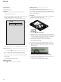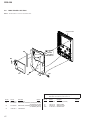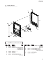
1
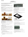
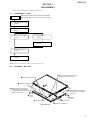
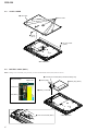
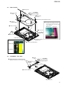
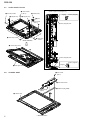
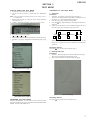
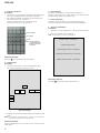
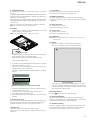
SERVICE MANUAL PRS-350 US Model Canadian Model AEP Model UK Model Ver. 1.0 2010.08 Note: Be sure to keep your PC used for service and checking of this unit always updated with the latest version of your anti-virus software. In case a virus affected unit was found during service, contact your Service Headquarters. SPECIFICATIONS Model name PRS-350 Power source Built-in rechargeable battery: 3.7 V DC, 940 mA USB communication: Hi-Speed USB (USB 2.0 compliant) Battery life (continuous playback) Maximum Battery: Approx. 10,000 continuous page turns when reading only *1 *1 Measured using a text based content in ePub format and a fully charged battery, consecutive page-turns at approximately one second per page under the recommended operating temperature. Actual battery life may vary based on usage patterns and individual device. User available capacity Approx. 1.4 GB after initial setting Depending on size of pre-loaded excerpts, available memory capacity may vary. Operating/charging temperature 41°F to 95°F (5°C to 35°C) Dimensions (w/h/d) Approx. 104.3 × 145 × 8.5 mm (4 1/8 × 5 3/4 × 11/32 inches) Mass Approx. 155 g (5.47 oz.) Display: 127.0 mm (5") diagonal electrophoretic display 600 × 800 pixel, 0.127 × 0.127 pixel/mm 16-level gray scale Design and specifications are subject to change without notice. The contents of each book pre-loaded on this product are copyrighted works, edited with the cooperation of the publisher. Copyright laws prohibit copying the data of this product or the contents of this manual (illustrations, related documents, etc.) in whole or in part without the permission of the copyright holder. Additionally, use of the data of this product or the contents of this manual is not allowed without Sony’s permission except for personal use. Besides individually enjoying, it is against the copyright law to use any picture you recorded without prior consent of the copyright holder. Sony, the Sony logo, “BBeB”, “Reader”, “Reader Pocket Edition” and their logos are either trademarks or registered trademarks of Sony Corporation. Bitstream is a registered trademark, and Dutch, Font Fusion, and Swiss are trademarks, of Bitstream Inc. Microsoft, Windows, Windows Vista and Windows Media are trademarks or registered trademarks of Microsoft Corporation in the United States and / or other countries. Macintosh and Mac OS are trademarks of Apple Inc., registered in the U.S. and other countries. This PRS-350 contains Adobe® Reader® Mobile software under license from Adobe Systems Incorporated, Copyright © 1995-2009 Adobe Systems Incorporated. All rights reserved. Adobe and Reader are trademarks of Adobe Systems Incorporated. This product includes software developed by the OpenSSL Project for use in the OpenSSL Toolkit. (http://www.openssl.org/) Copyright© 1998-2008 The OpenSSL Project. All rights reserved. This product includes cryptographic software written by Eric Young ([email protected]). This product includes software written by Tim Hudson ([email protected]). For details on OpenSSL License, refer to “END USER LICENSE AGREEMENT” in the book list on the Reader. All other system names and product names appearing in this document are the registered trademarks or trademarks of their respective owners. Further, the trademark ™ and registered trademark ® symbols are not indicated throughout this document. Program ©2010 Sony Corporation Documentation ©2010 Sony Corporation FLEXIBLE CIRCUIT BOARD REPAIRING • Keep the temperature of soldering iron around 270 °C during repairing. • Do not touch the soldering iron on the same conductor of the circuit board (within 3 times). • Be careful not to apply force on the conductor when soldering or unsoldering. CAUTION Danger of explosion if battery is incorrectly replaced. Replace only with the same or equivalent type. DIGITAL BOOK READER 9-889-952-01 2010H05-1 © 2010.08 Sony Corporation Published by Sony Techno Create Corporation PRS-350 SECTION 1 SERVICING NOTES NOTE OF REPLACING BATTERY ASSY (BAT1) Exchange it for an absolutely new part when you remove the BATTERY ASSY (BAT1) built into this set. 4. Confirm “Test Mode Avaliable” is displayed on the screen. NOTE THE EACH BOARDS REPAIRING The mount parts on each boards installed in this set cannot exchange with single. When the each boards are damaged, exchange the entire mounted board. DISCRIMINATION OF THE INK INDICATOR 5inch ELEMENT Two kinds of the INK INDICATOR 5inch ELEMENT is used in this set (LG type or PVI type). Parts are different according to the difference of the INK INDICATOR 5inch ELEMENT. Confirm the shape of the Flexible Printed Cable of the INK INDICATOR 5inch ELEMENT when the INK INDICATOR 5inch ELEMENT of PRS-350 that repairs distinguishes which type. • LG type 5. Press the key as following order. [ ]→[ ]→[ ]→[ ] 6. After a while, indicate the test mode menu, enter the test mode. • Releasing the test mode Slide the [POWER] key for 5 seconds or more to turn the power off. Then, delete the file copied in “How to enter the test mode” from the “READER” drive. • How to change the LUT 1. Confirm the lot number of INK INDICATOR 5inch ELEMENT referring to the figure below. Note: Remove the MAIN board to confirm the lot number. • PVI type L -1.58 E505 lot number 2. Confirm the version and the LUT file of LUT corresponding to the lot number to each service headquarters. 3. Make the following folder under the “READER” drive. NOTE OF REPLACING THE COMPLETE MAIN BOARD OR CHASSIS ASSY Please do the following work when you exchange complete MAIN board or CHASSIS ASSY. Note: INK INDICATOR 5inch ELEMENT is included in CHASSIS ASSY. • • Write VCOM: Refer to “20. Write VCOM” on page 10. REWRITING THE LUT: Refer to this page. REWRITING THE LUT As for INK INDICATOR 5inch ELEMENT, the parameter that rewrites the screen of each lot number is different. This parameter is called LUT (Look Up Table). When replacing the complete MAIN board or CHASSIS ASSY (LG) (including INK INDICATOR 5inch ELEMENT) you need to rewrite the LUT. However, rewriting is not required if the lot number is the same. Note: LUT is written in IC2003 on the MAIN board. Refer to the following for the “How to enter the test mode” and “How to change the LUT”. • How to enter the test mode 1. Connect the set to PC by the USB cable. 2. The file for the test mode is copied under the “READER” drive. Note: Confirm the method of obtaining the file for test mode to each service headquarters. 3. Remove the set from PC. Then, the power supply automatically becomes on. 2 /Sony Reader/software/data/ 4. Copy the LUT file updated under the folder made in step 3, and change the file name to “lut.bin”. 5. The current LUT version displayed at the lower side of “Update Waveform” on test mode menu 1 (Example: “000003020605000218031B321B00” in the figure below). (Example of displaying current LUT version) 6. Touch the “Update Waveform” in the test mode menu page 1, it starts rewriting LUT version. 7. After about 10 seconds, screen changes into all white. 8. Press [RESET] key and reboot the set. 9. Enter the test mode again, and confirm LUT version has been updated. PRS-350 SECTION 2 DISASSEMBLY • This set can be disassembled in the order shown below. 2-1. DISASSEMBLY FLOW SET Note 1: Please detach the STYLUS ASSY beforehand. Note 2: Please take care not to lose the STYLUS ASSY. 2-2. ORNAMENT BOTTOM (Page 3) 2-3. CASE LOWER (Page 4) 2-4. BATTERY ASSY (BAT1) (Page 4) 2-5. MAIN BOARD (Page 5) 2-6. ORNAMENT TOP ASSY (Page 5) 2-7. CASE UPPER BLOCK (Page 6) 2-8. CHASSIS ASSY (Page 6) Note: Follow the disassembly procedure in the numerical order given. 2-2. ORNAMENT BOTTOM 4 Move the ornament bottom in the direction of arrow C and D. 7 two adhesives (ornament) 6 adhesive (ornament 2) 2 Shifting this part of ornament bottom slightly in the direction of arrow A and peel off paper adhesive (ornament). A C 1 screw (M1.4) D 3 Shifting this part of ornament bottom slightly in the direction of arrow B. B 1 screw (M1.4) 8 ornament bottom – Rear side view – 5 three claws 6 adhesive (ornament 2) 3 PRS-350 2-3. CASE LOWER 5 case lower 4 seven claws 2 screw (M1.4) 1 two step screws (panel) 3 – Rear side view – 2-4. BATTERY ASSY (BAT1) Note: Exchange it for an absolutely new part when you remove the BATTERY ASSY (BAT1) built into this set. 4 Pull this part of sheet (BATT) and lift the battery assy. :LUHSURFHVVLQJ MAIN board 1 sheet (cable) 5 battery assy (BAT1) battery wire 3 battery connector sheet (BATT) 2 Turn over the sheet (BATT). 4 –5HDUVLGHYLHZ– PRS-350 2-5. MAIN BOARD 9 sheet (stylus) (for PINK) 4 seven screws (M1.4) 0 sheet (LED) 4 four screws (M1.4) BATT board qa MAIN board (including BATT board) 5 adhesive (CONN_PWB) Note: The state of the 23 pin FPC when the MAIN board is installed must curve. Do not dig into under the MAIN board and do not bend. 3 battery connector MAIN board 6 23 pin FPC 8 23 pin FPC 1 sheet (cable) – Rear side view – :LUHSURFHVVLQJ 7 ink indicator element flexible board MAIN board 2 Turn over the sheet (BATT). battery wire sheet (BATT) 2-6. ORNAMENT TOP ASSY 1 screw (M1.4) 3 Shifting these parts of ornament top assy slightly in the direction of arrow A and B. 2 screw (M1.4) (for PINK) 6 sheet (ornament) A 5 two claws B 4 7 ornament top assy – Rear side view – 5 PRS-350 2-7. CASE UPPER BLOCK 4 two step screws 1 magnet assy 5 three screws (M1.4) Note: When installing the magnet assy, note the position of cushion (magnet) of the magnet assy. 2 sheet (LED) magnet cushion (magnet) 1 magnet assy 3 plate 5 two screws (M1.4) cushion (magnet) side 4 three step screws – Rear side view – 4 three step screws 8 chassis assy block 7 6 cushion (magnet) side cushion (magnet) magnet 9 case upper block 2-8. CHASSIS ASSY 1 two screws (M1.4) 5 KEY board block 3 adhesive (SW_PWB) 4 two cushions (stylus) 2 6 chassis assy 6 – Front side view – PRS-350 SECTION 3 TEST MODE HOW TO ENTER THE TEST MODE 1. Connect the set to PC by the USB cable. 2. The file for the test mode is copied under the “READER” drive. Note: Confirm the method of obtaining the file for test mode to each service headquarters. 3. Remove the set from PC. Then, the power supply automatically becomes on. 4. Confirm “Test Mode Avaliable” is displayed on the screen. OPERATION OF THE TEST MODE 1. Test Panel Procedure: 1. Touch the “Test Panel” in the test mode menu page 1. The screen is changed into the image files. (all image files of in the directly as “/Sony Reader/software/images”) 2. Press the [<]/[>] keys, change the image files. 3. Press the [ ] key, image file display size change to 600×800 or 500×700. 4. If there are no image files, screen is filled with grayscale color. Press the [<]/[>] keys, change the grayscale color. > 5. Press the key as following order. [ ]→[ ]→[ ]→[ ] 6. After a while, indicate the test mode menu, enter the test mode. 7. Press the [<]/[>] keys, change the test mode menu page 1/page 2. WHITE < > LIGHT GRAY < > DARK GRAY < > BLACK < When the setting of “17. Slideshow Setting” is turning on, the image files (or grayscale color) are changes by the automatic operation. Releasing method: Press the [ ] key, return to the test mode menu 1. 2. Drawing with point Procedure: 1. Touch the “Drawing with point” in the test mode menu page 1. The screen is changed into the drawing check. 2. The scanned coordinate is displayed while dragging. (Test mode menu page 1) (Test mode menu page 2) RELEASING THE TEST MODE Slide the [POWER] key for 5 seconds or more to turn the power off. Then, delete the file copied in “HOW TO ENTER THE TEST MODE” from the “READER” drive. (Screen display) Releasing method: Press the [ ] key, return to the test mode menu 1. 7 PRS-350 3. Test TP Coordinate Procedure: 1. Touch the “Test TP Coordinate” in the test mode menu page 1. The screen is changed into the touch panel coordinate. 2. The scanned coordinate is displayed pen down and pen up. The grid is drawn every 100 pixels. All the touch panel data is recorded in the log file. (pen down, pen move, pen up, pressure) screen coordinate 5. Check battery Touch the “Check battery” in the test mode menu page 1. Display of the right side of “Check battery” on test mode menu changes into the display of the battery level. 6. Factory Initialize Touch the “Factory Initialize” in the test mode menu page 1. Clean up all the evidence and reset all settings, then shutdown. 7. Version confirmation Procedure: 1. Touch the “Version confirmation” in the test mode menu page 1. 2. Each version of this set are displayed. Note: “Preload contents version” is not displayed. raw coordinate pressure Note: The value displayed in "pressure" is invalid because of the optical touch panel. Firmware version: 1.0.00.08100 Preload contents version: Preload Partition version: 1.0.00.08100 (Screen display) eDictionary contents version: 1.0.00.07150 Releasing method: Press the [ ] key, return to the test mode menu 1. Installer Launcher version: 1.0.00.08100 4. Test All Keys Procedure: 1. Touch the “Test All Keys” in the test mode menu page 1. The screen is changed into the all keys state. (Screen display) Releasing method: Press the [ ] key, return to the test mode menu 1. HOME PREV NEXT SIZE OPTION VOL+ VOL- (Screen display) 2. Each keys are pressed, the display changed from white into the black. Note: This set doesn’t respond to the [VOL –]/[VOL +] keys. Release this mode after having finished pressing other keys. Releasing method: Press the [OPTION] key for 3 seconds or more, return to the test mode menu 1. 8 PRS-350 8. Update Waveform In this mode, it is possible to confirm the variation of LUT and rewrite. As for INK INDICATOR 5inch ELEMENT, the parameter that rewrites the screen of each lot number is different. This parameter is called LUT (Look Up Table). When replacing the complete MAIN board or CHASSIS ASSY (including INK INDICATOR 5inch ELEMENT) you need to rewrite the LUT. However, rewriting is not required if the lot number is the same. Note: LUT is written in IC2003 on the MAIN board. Procedure: 1. Confirm the lot number of INK INDICATOR 5inch ELEMENT referring to the figure below. Note: Remove the MAIN board to confirm the lot number. 11. Log Extract Touch the “Log Extract” in the test mode menu page 2. The device saves the log files of using right now. 12. NAND Log Extract Touch the “NAND Log Extract” in the test mode menu page 2. The device saves the log files of using last time before rebooted or shutdown. 13. Self Log Extract It is the tool for the developer. This mode is not used in servicing. 14. Log Convert It is the tool for the developer. This mode is not used in servicing. 15. Calibration Note: When CHASSIS ASSY (LG) is exchanged, it is necessary to execute this mode. Procedure: 1. Touch the “Calibration” in the test mode menu page 2. The screen is changed into the touch panel calibration. L -1.58 E505 lot number 2. Confirm the version and the LUT file of LUT corresponding to the lot number to each service headquarters. 3. Make the following folder under the “READER” drive. /Sony Reader/software/data/ 4. Copy the LUT file updated under the folder made in step 3, and change the file name to “lut.bin”. 5. The current LUT version displayed at the lower side of “Update Waveform” on test mode menu 1 (Example: “000003020605000218031B321B00” in the figure below). (Example of displaying current LUT version) 6. Touch the “Update Waveform” in the test mode menu page 1, it starts rewriting LUT version. 7. After about 10 seconds, screen changes into all white. 8. Press [RESET] key and reboot the set. 9. Enter the test mode again, and confirm LUT version has been updated. 9. Reset Device Lock The current state of device lock and the password are displayed on the right side of “Reset Device Lock” of test mode menu page 1. Touch the “Reset Device Lock” to reset the device lock. 10. Power Off Touch the “Power Off” in the test mode menu page 1. After a while, the screen display is changed white, so power is turned off. (Screen display) 2. Touch the top left point and the bottom right point to calibration. Then, touch the right upper, left bottom, and center point to confirm the result of calibration. It return to the test mode menu 2 when the calibration ends. Releasing method: Press the [ ] key, return to the test mode menu 2. 16. Check Temperature Touch the “Check Temperature” in the test mode menu page 2. Display of the right side of “Check Temperature” on test mode menu changes into the display of the temperature. 17. Slideshow Setting Touch the “Slideshow Setting” in the test mode menu page 2, slideshow on/off changes whenever it touch the “Slideshow Setting”. The setting is on, next image is shown every 3 seconds. 9 PRS-350 18. Test Audio Not used in PRS-350. 19. Test Battery Life Procedure: 1. Make the following folder under the “READER” drive. 20. Write VCOM In this mode, the VCOM voltage can be rewritten. The VCOM voltage for INK INDICATOR 5inch ELEMENT varies for each INK INDICATOR 5inch ELEMENT. When replacing the complete MAIN board or CHASSIS ASSY (LG) (including INK INDICATOR 5inch ELEMENT) you need to rewrite the VCOM voltage. /Sony Reader/software/books/ 2. Copy the book contents file supported in this set (ePub, PDF, text, RTF, BBeB) under the folder made in step 1. 3. Touch the “Test battery Life” in the test mode menu page 2. Procedure: 1. Confirm the VCOM voltage for INK INDICATOR 5inch ELEMENT referring to the figure below. Note: Remove the MAIN board to confirm the VCOM voltage. 1 seconds ONE ALL L -1.58 E505 VCOM voltage 2. Make the text file, and write the VCOM voltage confirmed in step 1. The VCOM voltage is described by the unit of mV that omits minus (Write “1580” when it is printed on the label as “–1.58”). Then, change the file name to “Vcom.dt”. 3. Make the following folder under the “READER” drive. /Sony Reader/software/data/ (Screen display) 4. Copy the file made in step 2 under the folder made in step 3. 5. The current VCOM voltage displayed at the lower side of “Write VCOM” on test mode menu 2 (Example: “–2.112 V” in the figure below). 4. Touch the “ONE” or “ALL”, and the page is turned until the battery runs down. Note: The battery have run out if this mode is executed. Release this mode by pressing the [ ] key when you want to stop it on the way. ONE: ALL: Page of one book in the copied books is turned. Page of all book in the copied books is turned. (Example of displaying current VCOM voltage) 5. Whenever 100 pages are turned, the result is maintained in the following file. /Sony Reader/software/books/counter Releasing method: Press the [ ] key, return to the test mode menu 2. 10 6. Touch the “Write VCOM” in the test mode menu page 2, it starts rewriting the VCOM voltage. 7. Confirm the VCOM voltage has been updated. PRS-350 SECTION 4 EXPLODED VIEWS Note: • -XX and -X mean standardized parts, so they may have some difference from the original one. • Items marked “*” are not stocked since they are seldom required for routine service. Some delay should be anticipated when ordering these items. 4-1. • The mechanical parts with no reference number in the exploded views are not supplied. • Color Indication of Appearance Parts Example: KNOB, BALANCE (WHITE) . . . (RED) ↑ ↑ Parts Color Cabinet’s Color • Abbreviation CND : Canadian model CASE AND ORNAMENT SECTION Note: This illustration is view from the case lower side. 9 2 7 6 10 3 4 11 (for PINK) 8 8 10 MAIN board section 2 4 5 1 Ref. No. Part No. Description 1 1 1 2 3 4-194-493-01 4-194-493-11 4-194-493-21 4-264-830-11 4-194-495-01 CASE LOWER (SILVER) CASE LOWER (PINK) CASE LOWER (BLUE) (AEP, UK) SCREW (M1.4) ORNAMENT BOTTOM (SILVER) 3 3 4 4 5 4-194-495-11 4-194-495-21 4-264-830-41 4-264-830-51 4-198-988-01 ORNAMENT BOTTOM (PINK) ORNAMENT BOTTOM (BLUE) (AEP, UK) SCREW (M1.4) (for PINK/BLUE) SCREW (M1.4) (for SILVER) SCREW (PANEL), STEP (for PINK/BLUE) 5 4-198-988-11 SCREW (PANEL), STEP (for SILVER) Remark Ref. No. Part No. Description Remark 6 7 7 7 4-264-830-31 X-2549-077-1 X-2549-081-1 X-2549-082-1 SCREW (M1.4) ORNAMENT TOP ASSY (S) (SILVER) ORNAMENT TOP ASSY (P) (PINK) ORNAMENT TOP ASSY (N) (BLUE) (AEP, UK) 8 9 9 9 10 4-258-178-01 A-1786-740-A A-1799-066-A A-1799-099-A 4-263-031-01 ADHESIVE (ORNAMENT) STYLUS ASSY (SILVER) STYLUS ASSY (P) (PINK) STYLUS ASSY (L) (BLUE) (AEP, UK) ADHESIVE (ORNAMENT 2) 11 4-263-320-01 SHEET (ORNAMENT) (for PINK) 11 PRS-350 4-2. MAIN BOARD SECTION Note 1: This illustration is view from the MAIN board. chassis section 56 54 (for PINK) BATT board 51 55 BAT1 51 53 52 Note 2: Exchange it for an absolutely new part when you remove the BATTERY ASSY (BAT1) built into this set. Ref. No. Part No. Description 51 52 4-264-830-31 X-2549-893-1 52 X-2549-894-1 53 1-882-536-11 SCREW (M1.4) MAIN BOARD, COMPLETE (Including BATT board) (for SERVICE) (US, CND) MAIN BOARD, COMPLETE (Including BATT board) (for SERVICE) (AEP, UK) 23PIN BOARD 12 Remark Ref. No. Part No. Description 54 4-198-349-01 SHEET (LED) (for PINK) 55 56 BAT1 4-265-772-01 4-259-734-01 A-1786-739-A SHEET (CABLE) SHEET (STYLUS) BATTERY ASSY Remark PRS-350 4-3. CHASSIS SECTION Note 1: This illustration is view from chassis side. 107 107 108 102 101 106 107 109 110 102 111 105 103 104 Note 2: Refer to “DISCRIMINATION OF THE INK INDICATOR 5inch ELEMENT” on page 2 when you exchange Ref. No. 104 or Ref. No. 108. Ref. No. Part No. Description 101 102 103 104 A-1794-477-A 4-264-830-41 4-195-096-01 A-1786-737-A 104 A-1786-738-A MAGNET ASSY SCREW (M1.4) PLATE CHASSIS ASSY (PVI) (Including INK INDICATOR 5inch ELEMENT) (PVI type) CHASSIS ASSY (LG) (Including INK INDICATOR 5inch ELEMENT) (LG type) KEY BOARD, COMPLETE SCREW (M1.4) STEP SCREW CASE_UPPER_SERVICE_ASSY (S-LG) (SILVER) (LG type) CASE_UPPER_SERVICE_ASSY (S-PVI) (SILVER) (PVI type) 105 106 107 108 A-1786-995-A 4-264-830-31 4-195-337-01 X-2580-012-1 108 X-2580-013-1 Remark Ref. No. Part No. Description Remark 108 X-2580-014-1 108 X-2580-015-1 108 X-2580-016-1 108 X-2580-017-1 109 4-198-355-01 CASE_UPPER_SERVICE_ASSY (P-LG) (PINK) (LG type) CASE_UPPER_SERVICE_ASSY (P-PVI) (PINK) (PVI type) CASE_UPPER_SERVICE_ASSY (P-LG) (BLUE) (LG type) (AEP, UK) CASE_UPPER_SERVICE_ASSY (P-PVI) (BLUE) (PVI type) (AEP, UK) CUSHION (STYLUS) 110 111 4-261-940-01 4-198-349-01 ADHESIVE (SW_PWB) SHEET (LED) 13 PRS-350 SECTION 5 ACCESSORIES Ref. No. Part No. Description 1-838-503-21 4-257-508-11 CABLE, USB (MICRO B) (USB cable) QUICK START GUIDE (PAPER) (ENGLISH, FRENCH) QUICK START GUIDE (PAPER) (GERMAN, DUTCH) (AEP, UK) QUICK START GUIDE (PAPER) (SPANISH, ITALIAN) (AEP, UK) 4-257-508-21 4-257-508-31 14 Remark PRS-350 MEMO 15 PRS-350 REVISION HISTORY Checking the version allows you to jump to the revised page. Also, clicking the version at the top of the revised page allows you to jump to the next revised page. Ver. Date 1.0 2010.08 Description of Revision New