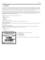
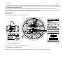
1
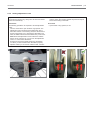
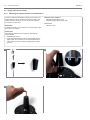
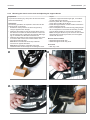
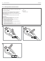
SERVICE MANUAL
WHEELDRIVE
EN
2 |
WheelDrive
WheelDrive
| 3
© 2014 Handicare
All rights reserved.
The information provided herein may not be reproduced and/or published in any form, by print, photo print, microfilm or any other
means whatsoever (electronically or mechanically) without the prior written authorisation of Handicare.
The information provided is based on general data concerning the constructions known at the time of the publication of this
manual. Handicare executes a policy of continuous improvement and reserves the right to changes and modifications.
The information provided is valid for the product in its standard version. Handicare cannot be held liable for possible damage
resulting from specifications of the product deviating from the standard configuration.
The available information has been prepared with all possible diligence, but Handicare cannot be held liable for possible errors in
the information or the consequences thereof.
Handicare accepts no liability for loss resulting from work executed by third parties.
Names, trade names, etc. used by Handicare may not, as per the legislation concerning the protection of trade names, be
considered as being available.
4 |
WheelDrive
WheelDrive
Table of content | 5
Table of content
1
Introduction........................................................................................................................................................... 6
1.1 This manual
6
1.2 Identification of the product
6
1.3 Symbols used in this manual
7
1.4 Remarks before use
7
2
Safety ................................................................................................................................................................... 8
2.1 Personnel qualification
8
2.2 Identification on the product
8
2.3 Temperature
8
2.4 Electromagnetic radiation and interference
8
2.5 Markings on the WheelDrive
9
2.6 Technical specifications
9
2.7 Modifications / Adaptations
9
3
Parts in box and tools to use .............................................................................................................................. 10
3.1 Parts in box
10
3.2 Tools to use
10
4
Spare parts ......................................................................................................................................................... 11
4.1 Use of the parts lists
11
01 WheelDrive exploded view
12
5
Service instructions ............................................................................................................................................ 13
5.1 Glossary
13
5.2 Maintenance plan
13
5.3 Quick release axle (QRA)
15
5.4 Quick release axle instructions
16
5.4.1 Mounting the variable quick release axle (QRA)
16
5.4.2 Releasing the QRA balls
17
5.4.3 Setting the QRA balls
18
5.4.4 Setting adjustment screw
19
5.5 Support block instructions
20
5.5.1 Mounting the support blocks on the WheelDrive
20
5.5.2 Mounting the wheels on the chair and adjust the support blocks
21
5.5.3 Mounting additional extender brackets
22
5.6 Maintenance instructions
23
5.6.1 Mounting the tyres
23
5.6.2 Charger connector cover
24
5.6.3 Battery contacts cleaning
25
5.6.4 Anti-tip
26
5.6.5 Parameter setting
27
6
Troubleshooting .................................................................................................................................................. 28
7
Technical product information............................................................................................................................. 29
7.1 CE Declaration and standards
29
7.2 Technical specifications
29
8
Warranty ............................................................................................................................................................. 30
8.1 Definitions of terms
30
8.2 Warranty period table
30
6 | Introduction
1
WheelDrive
Introduction
1.1 This manual
This service manual explains the mounting of the WheelDrive onto a manual wheelchair frame. The WheelDrive is compatible
with most common wheelchair frames in the market. The mounting can be done with a number of standard parts, supplied with
the WheelDrive wheels. For each wheelchair frame model a different setting is needed. Once a wheel is set for a certain frame
construction, it cannot be put directly onto another frame construction; an adjustment to the settings is required.
Mechanics who do the mounting and repairs on this Power assist must be well trained and familiar with the repair methods and
the maintenance of the WheelDrive. Always make sure that the work is carried out safely, particularly with respect to procedures
requiring the Power assist to be lifted up. We advise that you contact our technical helpdesk before doing repair work on a
WheelDrive that has been involved in an accident.
The following specifications are important when ordering parts:
• Model
• Year of manufacture
• Colour
• ID-number
• Part number
• Name of the part concerned
This information is provided on the identification plate. See 'Identification of the product'.
Available documentation
This manual will help you to service the Power assist. Other relevant document available / required to service the Power assist is
the user manual
Service and technical support
For information concerning specific settings, maintenance or repair works please contact the Handicare Customer Service
department. They are always prepared to help you. Ensure you have at hand:
• Model
• Year of manufacture
• ID-number
1.2 Identification of the product
A
C
The identification plate contains the following data:
A. Article number
B. Date of manufacture
C. Left or right wheel
D. Identification number
See for the location of the identification plate ´markings on the WheelDrive´.
D
B
WheelDrive
Introduction | 7
1.3 Symbols used in this manual
Note!
Pointing out possible problems to the user.
Caution!
Advice for the user to prevent damage to the product.
Warning!
Warnings for the user to prevent personal in jury.
Not following these instructions may result in physical injury, damage to the product or damage to the environment!
1.4 Remarks before use
Note!
Pull of the rubber caps from the main battery contact, otherwise you do not have power for the system
Charge the battery first, before use
8 | Safety
2
WheelDrive
Safety
2.1 Personnel qualification
Repairs may only be carried out by trained and authorised service technicians.
During the execution of their work, they are at all times fully responsible for the fulfilment of locally applicable safety guidelines
and standards.
Temporary employees and persons in training may only carry out repair and replacement work under the supervision of an
authorised service technician.
2.2 Identification on the product
Safety
Safety information is indicated with the warning symbol.
Warning!
Follow the instructions carefully next to these warning symbols! Not paying careful attention to these instructions could result in
physical injury or damage to the Power assist or the environment. Wherever possible, safety information is also provided in this
manual in the relevant chapter.
2.3 Temperature
Warning!
Avoid physical contact with the WheelDrive motor. The motor is continuously in motion during use and can reach high
temperatures. After use, the motor will cool down slowly. Physical contact may cause burns.
Ensure that the WheelDrive is not exposed to direct sunlight for extended periods of time. Certain parts of the WheelDrive
become hot if exposed to the sun for too long. This may cause burns or skin irritation.
2.4 Electromagnetic radiation and interference
The Power assist has been tested for compliance with the applicable requirements regarding electromagnetic radiation (EMC
requirements).
Note!
It cannot be excluded that electromagnetic radiation emanating from mobile telephones, medical apparatus and other sources,
may have an influence on the Power assist.
It cannot be excluded that the Power assist will interfere with the electromagnetic fields of, for example, shop doors, burglar alarm
systems and/or garage door openers.
In the unlikely event that such problems do occur, you are requested to notify your dealer immediately.
The Power assist can be affected by sources of radio waves, such as radio and TV transmitters, amateur radio stations, lifts,
transmitting equipment, stereo radios and mobile telephones. If the Power assist electronics are not well shielded, sensitive
electrical devices, such as shop alarm systems and garage door openers, can be affected. The WheelDrive has been tested for
such interference. Please report any problems of this nature to your dealer immediately.
Note:
There is no easy way of testing the effects of radio waves on the general immunity of the Power assist.
WheelDrive
Safety | 9
2.5 Markings on the WheelDrive
Never remove or cover up the markings, symbols and instructions affixed to the Power assist. These safety measures must
remain present and clearly legible throughout the entire lifestam of the Power assist.
Replace or repair any markings, symbols or instructions that have become illegible or damaged immediately. Please contact your
dealer for assistance.
Product labels
The following sticker/label can be found on the product:
2.6 Technical specifications
No changes may be made to the technical specifications.
2.7 Modifications / Adaptations
Modifications, not executed by Handicare, to components and electronics of this product are not permitted.
10 | Parts in box and tools to use
3
WheelDrive
Parts in box and tools to use
3.1 Parts in box
The Wheeldrive set (left and right) is packed into 2 boxes. Each box contains the following parts,
• The user manual
• 1x left wheel or 1x right wheel
• 1x Chargers (Indes_SUP012)
• Mounting materials, 1x box with:
• 1x Quick release axle 12.7 mm, for 25- 75 mm receivers(E0706-4300A)
• 1x Quick release axle 12 mm, for 25-75 mm receivers (E0706-4400A)
• 1x Quick release axle 12,7 mm, for 37 mm receiver (AS-E0706-4800) with receiver 12,7 mm 37 mm long (ASE0706-4800)
or 1x Quick release axle 12,0 mm, for 37 mm receiver (AS-E0706-4800) with receiver 12,0 mm 37 mm long (ASE07064800)
• 2x Support Bumpers (E0706-5230)
• 1x Installation help for support bumpers (PP-E0706-0150A)
• 2x Extender bracket, short (E0706-0538A)
• 2x Extender bracket, long (E0706-0539A)
• 8x Bolts M8x10 (D7984-002-080010)
3.2 Tools to use
The tools below are needed for various mechanical settings and maintenance:
Quantity
1
1
1
1
1
1
1
1
1
1
1
1
Description
Screwdriver, medium
Screwdriver, crosshead
Hammer (plastic)
Chaser
Circlip pliers
Ring spanner
Torque wrench
Socket
Socket bit
Allen key
Locktite
Shock absorber adjustment key
Size (mm)
5
7 / 10 / 11 / 13 / 17
7 / 8 / 10 / 11 / 12 / 13 / 16 / 17
6
3/4/5/6/8
243
-
Caution!
Use only high-quality tools for the adjustment(s) described.
Make sure that the hexagon of the spanner is attached securely to the hexagon of the fastening article. This prevents the 'rotation'
of hexagons of fastening articles and spanners that may affect proper adjustment.
The following tools are needed for various electronic settings:
Quantity
Description
Function
1
PG - pc programmer
B-version
Adaptation of the drive programs and technical settings.
Reading out the fault history
1
PG - programmer unit
SPIB handheld
Alternative device for PC. Adaptation of the drive programs
and technical settings.
Reading out the fault history
PR0210
10237
WheelDrive
4
Spare parts | 11
Spare parts
4.1 Use of the parts lists
This document is meant as a reference to order parts for the WheelDrive.
How to order
When ordering parts, please specify:
• ID-number (see the identification plate)
• Group (to which the relevant part belongs)
• Article number
• Number of parts required
• Description (in the relevant language)
• Dimensions (if applicable)
Remark
• If a part does not have a position number, it means that the part concerned cannot be purchased separately. The part
concerned is part of the assembly shown. This assembly must be ordered as one piece. It has to be replaced in its entirety.
• Boxed position numbers refer to the relevant drawing.
Order address
Please mail or fax your orders to Handicare.
Service technicians
Repairs may only be carried out by trained and authorised service technicians. During the execution of their work they are at all
times fully responsible for the fulfilment of locally applicable safety guidelines and standards.
Temporary employees and persons in training may only carry out repair and replacement work under the supervision of an
authorised service technician.
12 | Spare parts
WheelDrive
01 WheelDrive exploded view
2
6
7
1a
1b
14a
14b
8
15
13
3
16
5
4
9a
9b
10a
10b
Pos
1a
1b
2
3
4
5
6
7
8
9a
9b
10a
10b
11
12
13
14a
14b
15
16
17
Qty
1
1
1
1
1
1
1
1
1
1
1
1
1
1
1
1
1
1
1
1
1
Article number
9007930
9007932
9007934
9007938
9007941
9007943
9007945
9007947
9007949
9007953
9007951
9007967
9007965
9007955
9008200
9007957
9007961
9007963
9007959
9008492
9009885
11
12
Description
Tyre 24" Rightrun lite grey/black
Tyre 24" Marathon plus evolution black
Tube 24" Schrader valve
Charger connector cover
USB cover (10 pieces)
Wheel handle and bracket
Cover for sensor box AA batteries (2 pieces)
WheelDrive charger
Drive rim assy
Quick release axle Ø12 mm
Quick release axle Ø12,7 mm
Quick release axle, short Ø12 mm
Quick release axle, short Ø12,7 mm
Support blocks assy
Support blocks assy, short
Battery pack
Anti-tip arm for 24" wheel, right
Anti-tip arm for 24" wheel, left
Anti-tip wheel (2 pieces)
Spoke guard 24"
Cleaner battery contacts WheelDrive
17
WheelDrive
5
Service instructions | 13
Service instructions
5.1 Glossary
Assist Rim – Big rim, located at same position of normal wheelchair.
Drive Rim – Small rim, extra rim located in the centre.
Handle safety feature – Auto shutdown function when handle is opened.
Anti-tip – Tip-over protection, located at the back of the wheelchair.
Sensor Box – Triangular shaped box, located between the spokes
5.2 Maintenance plan
The maintenance plan is a reference guide for maintenance and inspection of the WheelDrive. Below, we have indicated what
needs to be checked, how often this should be done and by whom.
Time span
Description
Daily
Weekly
Monthly
Charge batteries after each use
Check tire pressure
Inspect tire wear
Inspect support blocks fixture
Change batteries Sensor (both)
Inspect the drive
Inspect the electrical system
Inspect the battery
Inspect the safety tip feature
Inspect the rims
Overall inspection
Every 6 months
Service appointment
To be carried out by
User
X
X
X
X
X
Dealer
X
X
X
X
X
X
However there is a signaling to warn the user at low battery status, it is recommended to change the batteries of the SensorBox
every 6 months.
Warning
Do not use rechargeable batteries.
Maintenance plan should be carried out by the dealer every time the WheelDrive is presented for service-related matters.
Maintenance requirement for re-use
Clean battery contacts with special cleaner, to prevent extraordinary wear of contacts. Cleaner is available at Handicare.
Warning
Do not use other cleaners than provided by Handicare.
The following points most be carried out before re-use:
Annual inspection
1
Inspect the drive
Use assist rim to drive forwards
Use assist rim to drive backwards
Use Drive rim to drive forwards
Use Drive rim to drive backwards
Inspect electrical system
Check all status LEDS
Check for BEEP signaling
Check function of all buttons
Check handle safety feature
Inspect the battery
Check for damages
Check locking in the WheelDrive
Check charger connector cover
2
3
4
5
6
7
14 | Service instructions
WheelDrive
Annual inspection
1
2
3
4
5
6
7
Inspect anti-tip
Check movement anti-tip leg
Check anti-tip wheel
Check fixture anti-tip
Inspect Assist rim
Check for damages
Check movement
Check centre position
Inspect Drive rim
Check for damages
Check movement
Check center position
Overall
Check for tire wear
Check the support block installation
List of necessary repairs:
Handle safety feature
Handle safety feature prevents switching on the system with the handle in open position.
Be sure to put the handle in close position when operating the WheelDrive.
Batteries
The battery is fitted with gold plated contacts. Make sure contacts are clean and undamaged.
Warning
Ensure the batteries are always fully charged. Not using the batteries for an extended period of time can damage them. Do
not use the WheelDrive if the batteries are almost run down and never if the batteries are completely empty. This can seriously
damage the batteries and you may run the risk of coming to an unintended standstill
Batteries contain acids. Damaged batteries are a serious health hazard.
If the capacity of the batteries is continually decreasing so that the wheelchair can only be used for short trips, this means that the
batteries are reaching the end of their lifespan. The batteries then need to be replaced.
Anti-tip
The anti-tip can be positioned upwards or downwards.
Be sure to put the anti-tip in the downwards position before re-use.
Rims
The rim safety feature prevents using the WheelDrive when rims are operated during startup.
Be sure to leave the rims in idle and untouched condition about 3 seconds after switching on the WheelDrive.
Warning
At all time the rims must be able to move clearly from other objects. Any disturbance from burrs or bends will affect the drive
experience.
Overall
Tires must perform well under normal conditions. Insufficient inflation or over-inflation will reduce the drive experience. Cracks,
bumps or lack of profile may increase the risk of a flat tire.
Badly installed WheelDrive will reduce the drive experience. Refer to 5.4 and 5.5 to check the support blocks and axle setting.
Warning
Support blocks and axles subject to wear must be replaced! If ignored, hazardous events can occur. Risk of serious injury.
WheelDrive
5.3 Quick release axle (QRA)
Determine the QRA
Two types of quick release axles are provided.
• Quick release axle for receivers of 25-75 mm
• Quick release axle short for a receiver of 37 mm
Each type comes in 2 diameters: 12 and 12,7 mm. Be sure to determine the
right axle size before installing the WheelDrive. To determine the difference
between 12 or 12,7 mm, look at the rib in the middle of the QRA. Without a
rib is the 12,7 mm QRA and with a rib is the 12 mm.
Determine which QRA you want to use, based on the receiver applied on
the wheelchair frame. If you are not in the position of a proper measuring
device to determine the diameter of your axle receiver, you can also
determine the required axle diameter by trial and error: the axle has to be a
tight fit, so there should be no play and the axle can only be moved along
the length of the axle.
If the wheelchair frame consist a longer receiver, replace it with a shorter
one. If you want to apply the short QRA, use it for a receiver of 37 mm.
This might be useful for wheelchairs with a tilting mechanism. See the next
paragraph how to mount and adjust the QRA.
Service instructions | 15
16 | Service instructions
WheelDrive
5.4 Quick release axle instructions
5.4.1
Mounting the variable quick release axle (QRA)
Preparation
To prevent the risk of injury, always turn off the Power assist
and remove the battery.
Instructions
The following operations are required to mount the QRA:
• Screw the adjustment screw completely into the QRA.
This can be done by hand.
• Put the QRA in the motor housing and tighten with your
hand until you feel resistance.
• Tighten the axle completely into the housing. You need
to turn the axle many times until the axle is fully secured.
Warning! When the axle is not properly secured in the
motor, it may come loose!
1
Relevant article numbers
• 9007953 Quick release axle Ø12 mm
• 9007951 Quick release axle Ø12,7 mm
• 9007967 Quick release axle, short Ø12 mm
• 9007965 Quick release axle, short Ø12,7 mm
Tools used
• Open ended or ring spanner, 10 mm
2
3
Note! When the axle is not properly secured in the motor, it
may come loose!
WheelDrive
5.4.2
Service instructions | 17
Releasing the QRA balls
Preparation
To prevent the risk of injury, always turn off the Power assist
and remove the battery.
Tools used
• Screwdriver
Instructions
The following operations are required release the QRA balls:
• The QRA is locked if the slider is aligned with a ball.
Before you mount the WheelDrive to the wheelchair, the
QRA balls need to be released (unlocked).
• The side of the axle with the adjustment bolt is visible at
the front side of the wheel.
• Unlock the axle by turning the slider with a screwdriver
at the end of the axle. The slider indicator will become
unaligned with the balls.
• You can mount the WheelDrive to the wheelchair
1
locked
unlocked
3
2
18 | Service instructions
5.4.3
WheelDrive
Setting the QRA balls
Preparation
To prevent the risk of injury, always turn off the Power assist
and remove the battery.
Instructions
The following operations are required to set the QRA balls:
• Put the WheelDrive with anti-tip and the QRA completely
in the axle receiver. The anti-tip plate should touch the
axle receiver.
• Unscrew the QRA until a ball comes fully out of the axlesreceiver.
Warning! Do not unscrew the axle more than 10 mm
outwards (second pair of balls). The axle will not be
properly secured in the motor and may come loose!
• The QRA is in its correct position, to lock itself to the axle
receiver.
• Remove the wheel and adjust the QRA slider with a screw
driver by turning the screw at the top side. The slider
should be aligned with the ball to lock that ball at the
length of the axle receiver.
Warning! Make sure that the slider is absolutely in the
middle of the balls. If not, the slider may come unlocked
and loose to the wheelchair.
• Put the wheel back on the wheelchair frame by pushing
the release button located above the handle. By pushing
the button the slider is unaligned and unlocked. Be sure
the selected ball comes out of the axle receiver in a
locked position.
Tools used
• Open ended or ring spanner, 10 mm
• Screw driver
1
2
3
4
WheelDrive
5.4.4
Service instructions | 19
Setting adjustment screw
the balls cannot protrude from the QRA. The QRA will not
lock the axle in the receiver. Repeat the previous steps to
fine-tune the sttting of the QRA.
Preparation
To prevent the risk of injury, always turn off the Power assist
and remove the battery.
Instructions
The following operations are required to set the adjustment
screw:
• Turn the screw with a open ended or ring spanner. The
adjustment screw should touch the QRA button at the
front side. When it is not touching at all, the wheel cannot
be removed properly. If it is touching the QRA button too
hard, the slider will unlock and the wheel may come loose.
Note! When the adjustment screw touches the release
button do not continue. Tip; you can turn the adjustment
screw 1 or 2 mm before the button.
• End check: remove the wheel and put the wheel back
on. When you hear a distinct click the QRA is properly
adjusted. When you do not hear a distinct click, it means
Tools used
• Open ended or ring spanner, 6 mm
1
2
20 | Service instructions
WheelDrive
5.5 Support block instructions
5.5.1
Mounting the support blocks on the WheelDrive
In order to fixate the WheelDrive system to your frame, two
support blocks must be mounted on the anti tip plate, both
rotated closely to the frame in order to counter rotational
movement from the motor.
Preparation
To prevent the risk of injury, always turn off the Power assist
and remove the battery.
Relevant article numbers
• 9007955 Support blocks assy
• 9008200 Support blocks assy, short
Tools used
• Allen key 6 mm
Instructions
The following operations are required to assemble the
support blocks:
• Assemble the 4 parts
• Screw the support blocks onto the anti-tip plate with the
gripping bolt. The protrusion on the support block fits in
a hole next to the hole in which the gripping bolt will be
screwed.
1
3
2
WheelDrive
5.5.2
Service instructions | 21
Mounting the wheels on the chair and adjusting the support blocks
Preparation
To prevent the risk of injury, always turn off the Power assist
and remove the battery.
Instructions
The following operations are required to mount and set the
support blocks on the wheel:
• Position the anti-tip wheel 6 cm above the ground by
using th supplied carton triangle.
• Determine the position for the first support block close to
the frame that counters the rearward rotation of the motor
and the anti-tip plate. Tighten the support block-bolt finger
tigh, so the block can still rotate around the bolt.
• Determine the position for the second support block close
to the frame that counters the forwards rotation of the
motor and the anti-tip plate.
Note! Make sure that both blocks stop rotational
movement in opposite directions.
Note! Make sure that the supporting area of the
wheelchair frame is stiff enough for countering the motor
torque.
Tighten the support block-bolt finger tight, so the block
can still rotate around the bolt.
• Place the plastic film on the support block to create a
proper play for taking off the wheel.
• Rotate the support blocks one after another towards the
frame and tighten the bolt.
• Remove the plastic film from the block by pulling the pull
tab. It is important to remove the film smoothly, to make
sure the block and film are not too tight to the frame.
Note! The support blocks may not mount too lose. When
the blocks are loose along the frame, the anti-tip plate
rotates with the motor
Relevant article numbers
• 9007955 Support blocks assy
• 9008200 Support blocks assy, short
Tools used
• Allen key, 6 mm
1
2
3
4
22 | Service instructions
5.5.3
WheelDrive
Mounting additional extender brackets
Preparation
To prevent the risk of injury, always turn off the Power assist
and remove the battery.
In some cases there is insuffiecient space to position the
support blocks on the anti tip plate. In other cases the
support blocks might interfere with other wheelchair parts or
a tilting mechanism.
In that case additional extender brackets can be useful
• Rotate the support block against the frame and tighten the
bolt
Tools used
• Allen key, 6 mm
Instructions
The bracket with three mounting holes can be used in
different positions (see drawings).
• Search for a possible position for the bracket and
determine which holes are used.
• Fix the bracket with two bolts.
• Search for a possible position for the support blocks on
the bracket, close to the frame.
• Tighten the support blocks-bolt finger tight, so the blocks
can still rotate around the bolt.
1
3
2
WheelDrive
Service instructions | 23
5.6 Maintenance instructions
5.6.1
Mounting the tyres
Preparation
To prevent the risk of injury, always turn off the Power assist
and remove the battery.
Instructions
The following operations are required to mount the tyres:
• Note! Do not remove or change the rim protection.
The rim protection is custom designed to bear the high
pressure tires.
• Unlock the WheelDrive and remove from frame.
• Removal of the outside tire only in inwards direction. Do
not remove the outside tire to the front, damage to rims is
possible.
• Replacement tyres provided by Handicare come in 2
models. Schwalbe Right Run and Schwalbe Marathon
Plus Evo. Both are designed for indoor- and outdoor use.
The Marathon Plus Evo tyre has a pre-defined rolling
direction. Please pay attention when this type of tyre is
replaced or removed for any service.
• Remove tire like normal wheelchair tyres.
Relevant article numbers
• 9007930 Rightrun Lite Grey/Black
• 9007932 Marathon Plus Evolution Black
Tools used
• Normal tyre levers
1
2
3
4
Marathon Plus Evo
Right Run
24 | Service instructions
5.6.2
WheelDrive
Charger connector cover
Preparation
To prevent the risk of injury, always turn off the Power assist
and remove the battery.
Instructions
The following operations are required to replace the charger
connector cover:
• Unscrew the 2 bolts (REMFORM M3x6).
• Remove the charger connector cover.
• Mount the connector cover in reverse order
1
1
Relevant article numbers
• 9007938 Charger connector cover
Tools used
• Philips head screwdriver
WheelDrive
5.6.3
Battery contacts cleaning
Preparation
To prevent the risk of injury, always turn off the Power assist
and remove the battery
Instructions
• Clean all 4 contacts, refer to manual on cleaner.
Relevant article numbers
• 9009885 Contact cleaner
1
Service instructions | 25
26 | Service instructions
5.6.4
WheelDrive
Anti-tip
Preparation
• Unlock the Wheeldrive and remove from frame.
• To prevent the risk of injury, always turn off the Power
assist and remove the battery
Instructions
The following operations are required to replace the anti-tip:
• Remove the 3 screws
• Mount the Anti-tip in the desired position.
Note! Anti-tip are right and left oriented
1
Relevant article numbers
• 9007961 Anti-tip arm, right
• 9007963 Anti-tip arm, left
Tools used
• Allen key 4
• Loctite 243
2
1
1
WheelDrive
5.6.5
Service instructions | 27
Parameter setting
Preparation
Computer and USB connection
Relevant article numbers
• 9007941 USB cover
Instructions
• Switch on the WheelDrive.
• Remove the rubber cap on the WheelDrive controller.
• Make connection between the computer and the
WheelDrive.
• Startup the WheelDrive parameter program.
• Select the desired COM connection. Note! Make
sure both wheels, left and right, always use the same
parameter settings.
• Apply setting by clicking the desired parmeter and click
button load parameter
• Press disconnect
• Replace the rubber cap
Tools used
• Indes WheelDrive program
• Computer
• USB cable
1
2
28 | Troubleshooting
6
WheelDrive
Troubleshooting
Possible cause
Check
WheelDrive no function
•
•
•
•
Batteries placed?
Batteries placed correctly?
Batteries charged?
Check battery contacts at both sides.
WheelDrive has no support by the Assist rim
•
•
•
•
•
Is the Assist rim undamaged?
Are batteries placed in sensor box
Are batteries sufficient to power the sensor box
The use of rechargeable batteries (this is not allowed).
At start-up of the system the Assist rim is not in center position. This results
in warning beeps by the system. Refer to user manual for warning beeps.
WheelDrive has no support by the Drive rim
• Is the Drive rim damaged?
• Is the Drive rim bend in any way?
• At start-up of the system the Drive rim is not in center position. This results
in warning beeps by the system. Refer to user manual for warning beeps.
WheelDrive is driving by itself
(no input is given by user and the WheelDrive
starts to move)
• Check center position of Assist rim
• Check center position of Drive rim
• Check for damages both rims
WheelDrive does not charge
•
•
•
•
•
•
Check if plug is in wall outlet.
Check if plug is firmly placed in charger.
Check if plug is placed firmly in battery.
Check if the green indicator light is working on the charger.
When charging, the indicator changes to red.
If indicator is red flashing, an error is detected.
WheelDrive is beeping
• Refer to user manual.
WheelDrive installation problems
• Check correct installation
• Press lock button for installing and releasing wheel
• Remove wheel in a straight line outwards
WheelDrive
7
Technical product information | 29
Technical product information
7.1 CE Declaration and standards
This product complies with the COUNCIL DIRECTIVE 93/42/EEC of 14 June 1993 concerning medical devices. The product
also meets the following requirements and standards. This has been verified by independent test organizations.
Standard
Definition/description
EU guideline 93/42 EEC
Requirements as stated in Appendix 1 apply
EN 12183 (2009) Class B
Manual wheelchairs - Requirements and test methods
EN 12184 (2009) Class B
Electrically powered wheelchairs, scooters and their chargers - Requirements and test methods
ISO 7176-14 (2008)
Power and control systems for electrically powered wheelchairs and scooters - Requirements
and test methods
EN 62304 (2006)
Medical device software – Software life-cycle processes
ISO 7176-21 (2009)
Requirements and test mothods for electromagnetic compatibility of electrically powered
wheelchairs and scooters, and battery chargers
7.2 Technical specifications
Product
Model
WheelDrive right wheel
E0706-5500
WheelDrive left wheel
E0706-5501
WheelDrive
Class
Description
Indoor and outdoor use (EN12184 class B)
Unit
Additional width in reference with manual wheel per side
mm (inch)
Total additional width in reference with manual wheel
21,5 (0.8)
mm (inch)
43 (1.7)
Total weight without batteries
kg (lbs.)
9,7 (1.5)
Weight of the batteries (set)
kg (lbs.)
3,6 (0.6)
inch
22 / 24
km (mi)
km (mi)
20 (12.4)
12 (7.5)
mm (inch)
50 (2)
Wheel diameter
Distance range approx (ISO 7176-4)*
Assist rim
Drive rim
Climbing capacity for obstacles (outdoor), driving backwards
Maximum speed forward** (support until)
Operating temperature
Ingress Protection Rating
km (mi)
6 (3.7)
ºC
-10 and +40
Splashing water proof IPX4
Battery
NiMH, 24V, 3.8Ah
Battery charge temperature
ºC
Battery storage temperature
ºC
Battery service life
Maximum load capacity
Battery charger
Charging time (full-charge) approx
AA batteries sensor box
0 till +40
-20 till +40
500 load cycles
kg (lbs.)
130 (20.5)
N100-24, reference number Indes_SUP012
hours
2
A-brand Alkaline AA (LR6) battery, 2700mAh
* Range dependent on user weight, condition of tyres, type of terrain, condition of battery and weather
conditions
** Driving faster than 15 km/h is not allowed with a fully charged battery pack; a potential overvoltage will result in a shut-down
30 | Warranty
8
WheelDrive
Warranty
8.1 Definitions of terms
Definitions of terms used in this warranty:
• Consumable part: Part that is subjected to natural wear and tear or natural contamination during normal operation within the
lifetime of the product (section 9 of Handicare’s general terms and conditions of sale);
• Client: Those who purchase the product directly from Handicare;
• Corrective action: Repair, replace or refund of the product;
• Dealer: Those who re-sell the product to the User;
• Defect: Any circumstance due to which the product is not sound or fit to use, caused by a lack of quality of the material used to
manufacture the product as well as the quality of the manufacturing process;
• Option: An accessory delivered by Handicare to extend the standard product model;
• Product: Product that is delivered according to brochure or contract (e.g. wheelchair, scooter, battery-charger etc.);
• Part: Part of product that can be exchanged or replaced. This can be an option, accessory, service part or consumable part;
• Returns: Product or part that needs to be returned;
• RMA-process: Process to return goods, contact Handicare’s Customer Service;
• Service part: Part that is durable and may be subjected to natural wear and tear or natural contamination during normal
operation within the lifetime of the product.;
• User: Those who use the product;
• Warranty: The rights and obligations set forth in this document;
• Warranty period: The period of time during which the warranty is valid;
• Warranty provider: Handicare B.V., Vossenbeemd 104, 5705 CL Helmond, The Netherlands.
Notwithstanding the rights and obligations of Handicare, Client and User set forth in Handicare’s general terms and conditions
of sale, the rights of the Client and/or User towards Handicare in case of defects are limited to the provisions set forth in this
warranty. For the duration of the warranty period Handicare guarantees that the product is without defects.
In case of any defects the User is required –within two weeks after discovery of the defect- to contact the dealer. He has to
complete a return form and return the product or part via the RMA-process. Handicare will, at its sole discretion, take the
corrective action it seems fit under the given circumstances within a reasonable period of time (depends on nature of claim) from
receipt of the completed return form. The warranty period will not be extended after a corrective action.
8.2 Warranty period table
Manual wheelchairs
Description
Warranty period
Examples include, but are not limited to the parts mentioned below
Frame
2 years
Weldment/frame
Service Parts
New: 1 year after invoice
Repaired: 90 days after invoice
Brakes
Consumable
parts
40 days after invoice
Seat- and back textiles, wheels, griphandles etc.
Options/
Accessories
2 years
Headrests, legrests, drum brake etc.
Not being service part or consumable part.
Power wheelchairs
Description
Warranty period
Examples include, but are not limited to the parts mentioned below
Frame
2 years
Weldment/frame
Drive system
1 year
Transaxle, motor, motor brake
Electronics
1 year
Controller, controlling mechanism, wiring harness, electronic
components
Service Parts
New: 1 year after invoice
Repaired: 90 days after invoice
Brakes
Consumable
parts
40 days after invoice
Wheels, push handles etc.
Options/
Accessories
2 years
Mirror, mudguards etc.
Not being service part or consumable part.
Handicare will only accept shipment costs and corrective costs related to warranty on equipment during the warranty period.
WheelDrive
Warranty | 31
This warranty will void in case of:
• The product and/or its parts being modified or items having been added by others than Handicare;
• Changes in cosmetic appearance by use;
• Failure to observe the instructions for use and maintenance, use other than normal use, wear and tear, negligence, collateral
damage by neglect of earlier symptoms, overloading, third-party accidents, non-original parts used and defects not caused by
the product;
• Circumstances beyond our control (flood, fire, etc.).
This warranty does not cover:
• Tyres and inner tubes
• Batteries (covered by the battery manufacturer’s warranty).
Clients and/or Users have legal (statutory) rights under applicable national laws relating to the sale of consumer products. This
warranty does not affect statutory rights you may have nor those rights that cannot be excluded or limited, nor rights against the
entity from whom the product was purchased. Clients may assert any rights they have at their sole discretion.
INDES b.v.
P.O. box 265
7500 AG ENSCHEDE
The Netherlands
[email protected]
www.indes.eu
The WheelDrive is a product of Indes Production Management BV. and is in conformity with the provisions of the medical
devices directive concerning class l medical devices.