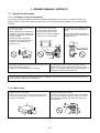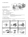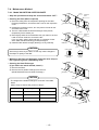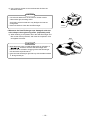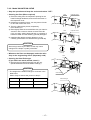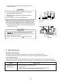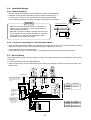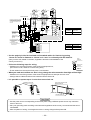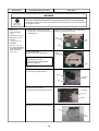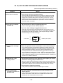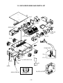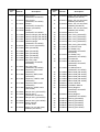
1
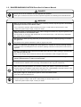
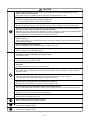
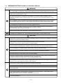
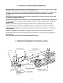
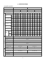
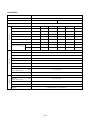
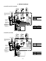
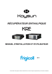
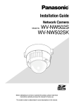
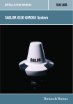
FILE NO. A06-003
SERVICE MANUAL
HEAT EXCHANGE VENTILATORS
VN-250TE
VN-350TE
VN-500TE
VN-800TE
VN-1KTAE
VN-500TE
PRINTED IN JAPAN, Mar.,2006 ToMo
CONTENTS
1. SAFETY CAUTIONS ................................................................................. 3
2. TECHNICAL POINTS (PERFORMANCE) ................................................ 7
3. REFERENCE DRAWING FOR INSTALLATION ....................................... 7
4. SPECIFICATIONS ..................................................................................... 8
5. NAME AND DIMENSION OF EACH PARTS .......................................... 11
6. WIRING DIAGRAM ................................................................................. 12
7. OWNER’S MANUAL (EXTRACT) ........................................................... 13
8. INSTALLATION MANUAL (EXTRACT) .................................................. 19
9. HOW TO DIAGNOSE THE TROUBLE ..................................................... 24
10. HOW TO REPLACE THE MAIN PARTS .................................................. 25
11. CHECK WHEN REPAIR WORK COMPLETED....................................... 28
12. Q & A FOR HEAT EXCHANGE VENTILATORS ..................................... 29
13. EXPLODED VIEWS AND PARTS LIST .................................................. 30
–2–
1. SAFETY CAUTIONS
The important contents concerned to the safety are described on the ventilator body and in this Service manual.
Preserve the described items after understanding clearly the following contents (indications/illustration symbols)
and reading this manual thoroughly.
n Explanation of indications
Indication
Meaning
DANGER
Indicates the contents which a danger such as death or serious injury is caused in emergency on the repair engineers or the surrounding third party by an incorrect work.
WARNING
Indicates the contents which a possibility such as death or serious injury is caused on the
repair engineers or the surrounding third party by an incorrect work, or on the customers
by a trouble of the products.
CAUTION
Indicates the contents which occurrence of injury (*) or damage of property is supposed on
the repair engineers or the surrounding third party by an incorrect work, or on the customers by a trouble of the products.
* Damage of property : expanded damage concerned to property/household effects or domestic animals/pets
n Explanation of illustration symbols
Illustration symbol
Meaning
Indicates prohibition (Never do it.).
The concrete contents of prohibition are indicated with illustrations or descriptions near the
illustration symbol.
Indicates forced work (Necessarily do it.).
The concrete contents of forced work are indicated with illustrations or descriptions near
the illustration symbol.
Indicates cautions (including danger/warning).
The concrete contents of cautions are indicated with illustrations or descriptions near the
illustration symbol.
1-1. Warning and Caution Exclusive in Service Work
WARNING
• Be sure to ask the customers not to let children close to the work place.
The tools or disassembled parts may cause an injury on children.
• Be sure to turn off the breaker before work when power-ON is unnecessary such as a case of
disassembling.
If doing so, an electric shock may be caused.
• Use the substitute parts corresponded to the model for repair. And do not modify the products.
It causes an abnormal operation or a trouble resulted in leakage or fire, that is a cause of customers’
disaster.
• For connection of the cut lead cables, connect the cables with application terminals, direct the
closed end side upward, and then apply the draining process.
If the post-process of connection is not carried out, a cause of customers’ disaster such as leakage or fire
generates.
• After the work, check the insulation resistance between live part (pin of SL terminal) and non-current
carrying part (motor frame) using a insulation megger (500V) and confirm 10MW or more is kept.
If the insulation resistance is not confirmed, a cause of customers’ disaster such as leakage or fire generates.
CAUTION
• Use the protective materials such as gloves, etc. for check/repair inside of the unit.
If touching inside of the unit with bare hands, an injury may be caused.
–3–
1-2. DANGER/WARNING/CAUTION Described in Owner’s Manual
DANGER
• Do not use as an air circulators for open-type burners (heaters).
When gas or oil stoves are used in the home, separate equipment for circulating the air should be used.
WARNING
• When any abnormal condition (scorching smell or others) is found, stop the operation immediately
and keep the exclusive circuit breaker “OFF”.
If you continue the operation without removing the cause, it could cause an electric shock or a fire.
• When the system needs a repair, consult your dealer.
• When the system is checked and the power cable undergoes maintenance, stop the operation, and
switch the exclusive circuit breaker “OFF”.
The internal fan is revolving at high speeds and can cause serious injury. And when using a stepladder,
etc., make sure to fix it properly.
• The external air intake opening should be positioned away from the exhaust openings of combustion gases etc.
The intake of such gasses could lead to a lack of oxygen in the room.
• If there is combustible gas leakage from other appliances, ventilate the room by opening windows.
If operation were to be attempted in such a situation, sparking at electrical contact points could cause an
explosion.
• Netting or something similar should be provided at the external air intake opening to prevent birds
etc. interfering with the unit.
Nests or other foreign objects should be removed. That could lead to a lack of oxygen in the room.
• If the supply cord is damaged, it must be replaced by the manufacturer or its service agent or a
similarly qualified person in order to avoid a hazard.
• The external air intake opening should not be positioned where discharged air may directly enter it.
A situation like this will lead to the room being contaminated and this may pose a health risk.
• When Heat Exchange Ventilators are relocated, contact your dealer or a professional installer.
Improper practice of installation could cause a drop of the unit, a water leakage, an electric shock or a fire.
• Ask the sales office or the engineering shop to perform the work.
• Don't push a finger or a stick into the open-air inlet or the exhaust outlet.
A fan with a high rpm will injure you.
• Modification of the system is strictly prohibited.
Improper practice of repair could cause a water leakage, an electric shock or a fire.
• When the system needs a repair, consult your dealer.
–4–
CAUTION
• If Heat Exchange Ventilators are not used for a long period of time, keep the exclusive circuit
breaker “OFF” for safety reasons.
If the power is left on, any build-up of dust could cause a heat generation or a fire.
• The system should never be used for any other purposes than intended such as for preservation of
foods, flora and fauna, precision devices or work of art.
• It could cause deterioration of foods or other problems.
• Install at a stable place of sufficient strength.
Please note that there might be some places not strong enough to install due the structure of building.
• Provide an exclusive circuit breaker that can completely break contacts on all the poles by more
than 3mm through direct connection to the power terminals.
Depending upon the environment for installation, it becomes necessary to install an earth leakage breaker.
Unless the earth leakage breaker is installed, it could cause an electric shock.
• Ask the sales office or the engineering shop to perform the work.
• Never fail to install the unit inside the heat insulting walls or, in other words, in the space insulated
from the open air.
If you install it outside or in the space equivalent to the open-air conditions, dew is condensed inside the
body in the winter season.
• The filter should be cleaned regularly.
Dust or dirt building-up on it can lead to a lack of oxygen in the room.
• Use gloves when cleaning the filter or heat exchange element.
Doing so will reduce any possibility of injury.
• It is strictly prohibited to place a container of combustible gas or liquid near Heat Exchange
Ventilators or to spray it directly with the gas or liquid.
It could cause a fire.
• Do not use outside the rated voltage.
It could cause a fire or an electric shock.
• Combustion apparatus should not be placed allowing a direct exposure to wind of Heat Exchange
Ventilators.
Incomplete combustion could occur on the apparatus.
• Don’t put a container of water on Heat Exchange Ventilators.
When water spills, it is likely to enter inside the unit and degrade electric insulation, possibly resulting in
an electric shock.
• Don’t incline Heat Exchange Ventilators when taking them out.
Otherwise, water remaining inside is likely to drop and wet the furniture or other property.
• Ask the sales office or the engineering shop to perform the work.
• Do not install in locations where harmful or corrosive gasses may be present (i.e. acidic, alkali,
organic solvent, paint gasses etc. from machinery or factories)
Installation in such a location could cause a gas-poisoning and a fire.
• Do not install in locations where oily smoke or soot may be present.
There is a possibility that oil will adhere to the filter, heat exchange element etc. and make operation impossible.
• Do not install in locations with high humidity, such as close to bathroom etc.
Installation in such a location could cause a breakdown.
• Don’t use benzene or metal brush when cleaning the filter and heat exchange element.
Otherwise, the unit will get unfit for use.
• Don’t blow directly against animals or plants.
Likely to cause bad effect on animals and plants.
• Do not wash Heat Exchange Ventilators with water.
It could cause an electric shock.
• Do not handle switches with a wet hand.
It could cause an electric shock.
–5–
1-3. WARNING/CAUTION Described in Installation Manual
WARNING
Never fail to ask the sales office from which you bought the unit or the installing service shop to install the
unit. If you install it by yourself, any inappropriate installing works would cause an electric shock or a fire.
Carry out the installing works accurately in line with this installation manual. Improper practice of installation
could cause an electric shocks or a fire.
Choose the installing place where is endurable in quality as well as in weight, then install the unit accurately
with adequate strength and completeness of installation in accordance with the installation manual.
Otherwise, it is likely to cause an electric shock, a fire, a drop of the unit, thus causing the injury on the
human body.
Carry out electrical work in accordance with the laws and regulations prevailing in the country concerned,
technical standard and explanation for work, and make absolutely sure that an exclusive circuit is used.
Any insufficient capacity of power circuit and improper work can result in electric shock and fire hazard.
The external air intake opening should be positioned away from the exhaust openings of combustion gases
etc. The intake of such gases could cause a lack of oxygen in the room.
Netting or something similar should be provided at the external air intake opening to prevent birds etc.
interfering with the unit. Nests or other foreign objects should be removed.
That could cause a lack of oxygen in the room.
When the system is checked and the power cable undergoes maintenance, stop the operation, and switch the
exclusive circuit breaker “OFF”. Otherwise, it could cause an electric shock.
Carry out the GND work. Never connect the GND wire to a gas pipe, a water supply pipe, a lightning conductor, a GND line of a telephone, etc. An incomplete GND wire is likely to cause an electric shock.
CAUTION
Provide an exclusive circuit breaker that can completely break contacts on all the poles by more than 3mm
through direct connection to the power terminals. Depending upon the environment for installation, it becomes
necessary to install an earth leakage breaker.
When you want to pierce the metal duct through the metal lath or the wire lath or the metal plate of the
wooden facility, do not forget to insulate electrically between the duct and the wall.
Otherwise, it would cause an electric shock or an electric leakage.
Don’t use other parts than specified (including the auxiliary parts) for installing works.
If you do not use the specified parts, it is likely to cause a drop of the unit, a fire, an electric shock, etc.
Install the outdoor duct in a falling gradient toward the outside so as to prevent water from coming in.
If it is not installed so, the building is likely to be flooded, wetting the household effects.
Heat-insulate the outdoor duct (including the indoor side, if necessary) to prevent dewing.
If heat insulation is not adequate, water likely goes indoor and wets the household properties.
When it is high humid and high temperature inside the ceiling, a ventilation system must be installed inside
the ceiling. Otherwise, it could cause a fire or an electric leakage.
Connect the power line and the connecting line with accuracy using the specified cables and fix them firmly
so as not to put the outer stress of the cables on the pin connecting area.
Incomplete connection or fixing is likely to cause a heat generation or a fire.
Install the power line and the connecting line with accuracy so the power source cover may not float.
If the installation of the power source cover is inappropriate, the pin connection area is likely to cause a heat
generation, a fire and an electric shock due to dust or powder.
Never install the unit near the place where there is a fear of leakage of an inflammable gas.
If gas happens to leak and stays around the unit, it is likely to cause a fire.
Don’t use the unit at the other voltages than the rated one. It could cause a fire or an electric shock.
Do not install the unit in locations with large amounts of oily smoke, such as food preparation areas.
It could cause a fire.
Don’t install the unit at the place of a high temperature or a flame. It could cause a heat generation or a fire.
Do not install in locations where harmful or corrosive gasses may be present (i.e. acidic, alkali, organic
solvent, paint gasses etc. from machinery or factories).
Installation in such a location could cause a gas-poisoning and a fire.
Do not install in locations with high humidity, such as close to bathroom etc. It could cause an electric shock
or an electric leakage etc.
–6–
2. TECHNICAL POINTS (PERFORMANCE)
• Energy-saving ventilation to save the cooling/heating cost because the heat energy (outside
air load) to be lost by ventilation is effectively recovered.
• Compact construction to downside the cooling/heating equipment with size corresponding
to heat energy amount to be recovered because the outside air load can be vastly decreased.
• By using the heat exchanger, humidity control effect which sucks the humidity approached
to near the humidity in the room.
• Comfortable ventilation by simultaneous air suction/discharge which sucked air approached
to the temperature in the room and the stable ventilation to be performed even in the high
airtight room.
• Noise-proof effect to prevent entering of outside noise or flowing of noise to outside.
• Suction/discharge air system on straight line which is easy to be designed or installed.
• The high-level long filter is mounted to increase the effect of dust collection for removing.
( Weight: 82%)
• Reverse installation up and down is possible, which 2 units use the same check port.
• Especially powerful notch is mounted, which can increase air volume and is selectable in
the main unit.
• Only one check port is used for all the maintenance works.
3. REFERENCE DRAWING FOR INSTALLATION
Supply Air Duct
Outside Intake Duct
Ceiling Suspension Bolt
Pipe Hood
SA
(Supply Air)
RA
(Outside Air)
Room Intake Duct
EA
(Exhaust Air)
OA
(Outside Air)
Room Intake Opening
(Supply/Exhaust Air Grill)
Heat Insulation
Material
Exhaust Air Duct
Pipe Hood
–7–
Inside Supply Opening
(Supply/Exhaust Air Grill)
4. SPECIFICATIONS
<VN-250TE, VN-350TE>
VN-250TE
Model
VN-350TE
Type
Concealed duct type
Ventilation system
Heat exchange
Normal ventilation
Rating
Heat exchange
Normal ventilation
50Hz 220 – 240V, 60Hz 220V
Extra
high
High
Extra
high
Low
High
Extra
high
Low
High
Extra
high
Low
High
Low
50Hz 0.48–0.5 0.46–0.48 0.37–0.39 0.47–0.5 0.46–0.48 0.37–0.39 0.63–0.65 0.59–0.6 0.56–0.57 0.61–0.63 0.57–0.6 0.54–0.56
Current
(A)
60Hz
0.59
0.55
50Hz 104–119 99–114
0.39
79–90
0.59
0.55
0.39
103–119 98–114
0.85
79–90
0.75
0.67
0.83
0.74
0.67
137–154 124–137 117–128 133–151 119–132 113–125
Power consumption (W)
Characteristics
Air volume
60Hz
128
118
78
128
118
77
178
149
132
176
145
131
50Hz
250
250
170
250
250
170
350
350
280
350
350
280
60Hz
250
250
135
250
250
135
350
350
240
350
350
240
50Hz
90
80
37
90
80
37
95
65
42
95
65
42
60Hz
125
100
30
125
100
30
155
90
43
155
90
43
50Hz
27–28
26–27
21–22
27–28
31–32
29–30
25–26
31–32
30–31
26–27
60Hz
28
26
21
28
26.5
21.5
33
30
22
33
30
23
50Hz
75
75
77
—
—
—
75
75
77
—
—
—
60Hz
75
75
78
—
—
—
75
75
79
—
—
—
50Hz
70
70
73
—
—
—
69
69
71
—
—
—
60Hz
70
70
75
—
—
—
69
69
73
—
—
—
50Hz
63
63
66
—
—
—
66
66
69
—
—
—
60Hz
63
63
68
—
—
—
66
66
71
—
—
—
(m³/H)
Static pressure
(pa)
Noise
26.5–27.5 21.5–22.5
(dB)
Temp. exchange rate (%)
In heating
Enthalpy
exchange
rate
(%)
In cooling
Frame
Zinc iron plate
Motor
4-pole capacitor dielectric motor (E type)
Construction
Sirocco fan
ABS resin
Heat exchanger
Combustion-proof sheet
Filter
Nonwoven fabric (Collection effect weighing method 82%)
Adapter
Mounting pipe diam.
ABS resin
(mm)
External dimension
(mm)
(Length x Width x Height)
Product mass
(kg)
Ø150
599 x 882 x 270
804 x 882 x 270
29
37
Package
Shape
Corrugated board package/ventilator
Dimension
(mm)
(Length x Width x Height)
Mass
(kg)
335 x 1138 x 795
335 x 1138 x 1000
34
42
No. of stacked boxes
Accessory
4
Installation Manual: 1, Owner’s Manual: 1
–8–
<VN-500TE, VN-800TE>
VN-500TE
Model
VN-800TE
Type
Concealed duct type
Ventilation system
Heat exchange
Normal ventilation
Rating
Heat exchange
Normal ventilation
50Hz 220 – 240V, 60Hz 220V
Current
Extra
high
High
Low
Extra
high
High
Low
Extra
high
High
Low
Extra
high
High
Low
50Hz
0.86–0.9
0.79–0.81
0.72–0.73
0.84–0.88
0.76–0.77
0.71–0.73
1.51–1.54
1.48–1.5
1.44–1.46
1.47–1.5
1.45–1.48
1.41–1.43
60Hz
1.14
1.0
0.81
1.12
0.96
0.8
2.05
1.92
1.68
2.04
1.87
1.68
(A)
50Hz 188–214 169–188 151–166 184–210 161–182 145–164 316–347 309–329 302–327 309–337 300–325 297–316
Power consumption (W)
Characteristics
Air volume
60Hz
244
202
162
243
196
161
424
391
347
417
387
346
50Hz
500
500
370
500
500
370
800
800
650
800
800
650
60Hz
500
500
310
500
500
310
800
800
575
800
800
575
50Hz
105
70
38
105
70
38
140
110
70
140
110
70
60Hz
165
85
33
165
85
33
190
100
50
190
100
50
50Hz
33–34
31–32
25–26
34–35
32–33
26.5–27.5
38–39
36.5–37.5
32–34
38.5–39.5
37–38
33–35
60Hz
35
31
23
36
33
24
39
36
31
39.5
37
31
50Hz
75
75
77
—
—
—
75
75
76
—
—
—
60Hz
75
75
79
—
—
—
75
75
77
—
—
—
50Hz
67
67
71
—
—
—
71
71
74
—
—
—
60Hz
67
67
74
—
—
—
71
71
75
—
—
—
50Hz
62
62
67
—
—
—
65
65
68
—
—
—
60Hz
62
62
69
—
—
—
65
65
69
—
—
—
(m³/H)
Static pressure
(pa)
Noise
(dB)
Temp. exchange rate (%)
In heating
Enthalpy
exchange
rate
(%)
In cooling
Frame
Zinc iron plate
Motor
4-pole capacitor dielectric motor (E type)
Construction
Sirocco fan
ABS resin
Heat exchanger
Combustion-proof sheet
Filter
Nonwoven fabric (Collection effect weighing method 82%)
Adapter
Mounting pipe diam.
Zinc iron plate
(mm)
External dimension
(mm)
(Length x Width x Height)
Product mass
(kg)
Ø200
Ø250
904 x 962 x 270
884 x 1322 x 388
43
71
Package
Shape
Corrugated board package/ventilator
Dimension
(mm)
(Length x Width x Height)
Mass
No. of stacked boxes
Accessory
(kg)
335 x 1218 x 1100
453 x 1538 x 1075
48
79
4
3
Installation Manual: 1, Owner’s Manual: 1
–9–
<VN-1KTAE>
VN-1KTAE
Model
Type
Concealed duct type
Ventilation system
Heat exchange
Characteristics
Rating
50Hz 220 – 240V
Extra high
High
Low
Extra high
High
Low
Current
(A)
1.97–2.04
1.85–1.93
1.68–1.76
1.95–2.03
1.84–1.92
1.67–1.74
Power consumption
(W)
399–445
360–399
332–367
392–438
358–392
329–362
1000
1000
810
1000
1000
810
Air volume
(m²/H)
Static pressure
(pa)
90
55
35
90
55
35
Noise
(dB)
37.5–38.5
36–37
31–33
38–39
36.5–37.5
31.5–33.5
(%)
75
75
76
—
—
—
In heating
71
71
73
—
—
—
In cooling
65
65
68
—
—
—
Temp. exchange rate
Enthalpy exchange rate
(%)
Frame
Zinc iron plate
Motor
4-pole capacitor dielectric motor (E type)
Construction
Sirocco fan
ABS resin
Heat exchanger
Combustion-proof sheet
Filter
Nonwoven fabric (Collection effect weighing method 82%)
Adapter
Zinc iron plate
Mounting pipe diam.
(mm)
Ø250
External dimension
(Length x Width x Height)
(mm)
1134 x 1322 x 388
(kg)
83
Product mass
Shape
Package
Normal ventilation
Dimension
(Length x Width x Height)
Mass
Corrugated board package/ventilator
(mm)
453 x 1538 x 1325
(kg)
91
No. of stacked boxes
Accessory
3
Installation Manual: 1, Owner’s Manual: 1
– 10 –
5. NAME AND DIMENSION OF EACH PARTS
<VN-250TE, VN-350TE, VN-500TE>
Number
2
6
5
9
10
Name
Quantity Note
1
Frame
1
2
Adapter
4
3
Terminal
1
4
Inspection Cover
1
5
Fan Sirocco
2
6
Motor Fan
2
7
Heat Exchanger
2
8
Filter
2
9
Damper
1
10
Motor Damper
1
11
Ceiling Suspension Fixture
4
12
Electric Parts Lid
1
J
E
EA
(Exhaust Air)
F
I
A
RA
(Room Air)
OA
(Outside Air)
G
H
SA
(Supply Air)
1
11
7
K
L
4-13 x 30
Oval Hole
M
N
P
B
C
8
12
3
Note) Model VN-250TE has one Heat Exchange.
Applicable Duct
C
4
Note)
Model
Nominal Diameter
VN-250TE
Ø150
VN-350TE
Ø200
VN-500TE
Unit: mm
Model
A
B
C
E
F
G
H
I
J
K
L
M
N
P
VN-250TE
599
882
95
810
655
19
142
315
142
135
159
270
Ø144
Ø164
VN-350TE
804
882
95
810
860
19
162
480
162
135
159
270
Ø144
Ø164
VN-500TE
904
962
107
890
960
19
202
500
202
135
159
70
Ø194
Ø210
<VN-800TE, VN-1KTAE>
6
8
10
9
H
E
EA
(Exhaust Air)
F
RA
(Room Air)
I
A
1
Frame
1
2
Adapter
4
3
Terminal
1
4
Inspection Cover
1
5
Fan Sirocco
2
6
Motor Fan
2
7
Heat Exchanger
3
G
5
Quantity Note
Name
Number
2
OA
(Outside Air)
Note)
G
H
SA
(Supply Air)
7
Filter
2
9
Damper
1
L
10
Motor Damper
1
11
Ceiling Suspension Fixture
4
12
Electric Parts Lid
1
4-13 x 30, Oval Hole
P
B
M
N
1
11
8
K
M+2
J
Note) Model VN-1KTAE has one Heat Exchange.
Applicable Duct
C
C
4
Model
3
Nominal Diameter
VN-800TE
12
Ø250
VN-1KTAE
Unit: mm
Model
A
B
C
E
F
G
H
I
J
K
L
M
N
P
VN-800TE
884
1322
85
VN-1KTAE
1134
1322
85
1250
940
19
228
428
612
194
218
388
Ø245
Ø258
1250
1190
19
228
678
612
194
218
388
Ø242
Ø258
– 11 –
6. WIRING DIAGRAM
<VN-250TE, VN-350TE, VN-500TE>
Damper
Motor
Red
Capacitor
Capacitor
Orange
CN–
SAFM
Divide the power lines running
to the switch and the main unit.
On the product. do not attach
more then one cable to each
terminal.
Yellow Blue
Low High
Whte
Extra
High
Black
Common
Black
Common
1 2 3 4 5 6 7
1 2 3 4 5 6 7 8
1 2 3 4 5 6 7
CN– 1 2 3 4 5 6 7 8
EAFM
1 2 3 4 5
1 2 3 4 5 CN–DM
NC
4
3
(Heat Exchange)
Power Source
Whte
Extra
High
Yellow
Yellow Blue
Low High
Blue
MS
Orange
Black
Exhaust
Air Fan
White
(Normal)
Red
Supply
Air Fan
NO
RY4
CM
1
1
(LINE)
CN8
CN7
CN6
CN5
(NEUTRAL)
RY4
NO
NC
NO
(1)
NO
RY5
RY3
CM
(2)
VN-350TE
Power Source
220-240V~50Hz/
220V~60Hz
VN-500TE
RY5
Operation Switch
(1) 0 (OFF)
(2) 1 (ON)
1 TM1
L 2
N 3
COMMON 4
LOW 5
HIGH 6
DAMPER 7
(3)
(4)
Air Flow Switch
(3) High
(4) Low
(5)
(6)
Function Select Switch
(5) Heat Exchange
Ventilation
(6) Normal Ventilation
To find out the function
of each switch.
Model
VN-250TE
CM
RY2
CM
RY3
NC
Switch
(To be procured
locally)
RY2
(Srcond main body)
Model
1 TM1
L 2
N 3
4
LOW 5
HIGH 6
DAMPER 7
Power Source
Capacitor
VN-250TE
2.0µF 450VAC
VN-350TE
3.0µF 450VAC
VN-500TE
3.5µF 450VAC
Third main body
<VN-800TE, VN-1KTAE>
Damper
Motor
Red
Capacitor
Power Source
CN–
SAFM
Divide the power lines running
to the switch and the main unit.
On the product. do not attach
more then one cable to each
terminal.
Whte
Extra
High
Yellow Blue
Low High
Whte
Extra
High
Black
Common
Black
Common
1 2 3 4 5 6 7
1 2 3 4 5 6 7 8
1 2 3 4 5 6 7
CN– 1 2 3 4 5 6 7 8
EAFM
3
Blue
Yellow Blue
Low High
Yellow
MS
Orange
Black
Capacitor
Orange
White
(Normal)
Exhaust
Air Fan
(Heat Exchange)
Red
Supply
Air Fan
1 2 3 4 5
1 2 3 4 5 CN–DM
NC
4
NO
RY4
CM
(LINE)
1
1
CN8
CN7
CN6
CN5
RY4
(NEUTRAL)
NO
RY3
NC
NO
(1)
NO
RY2
RY5
CM
CM
NC
CM
NO
RY1
(3)
(5)
(6)
Function Select Switch
(5) Heat Exchange
Ventilation
(6) Normal Ventilation
To find out the function
of each switch.
Model
Power Source
VN-800TE
220-240V~50Hz/
220V~60Hz
VN-1KTAE
220-240V~50Hz/
CM
1 TM1
L 2
N 3
COMMON 4
LOW 5
HIGH 6
DAMPER 7
(4)
Air Flow Switch
(3) High
(4) Low
RY1
NC
(2)
Operation Switch
(1) 0 (OFF)
(2) 1 (ON)
RY3
Switch
(To be procured
locally)
RY5
RY2
(Srcond main body)
1 TM1
Power Source
Model
L 2
N 3
COMMON 4
LOW 5
HIGH 6
DAMPER 7
Third main body
– 12 –
Capacitor
VN-800TE
8.0µF 450VAC
VN-1KTAE
10.0µF 450VAC
7. OWNER’S MANUAL (EXTRACT)
7-1. Specific Caution Items
7-1-1. Checking Location of Installation
This Energy Recovery Ventilators have been designed especially for use in offices, conference rooms, etc.
Please check to ensure that neither the main unit nor the inlet-outlet grill are installed in any of the following
locations.
Locations exposed to high temperatures or direct flame.
Avoid installing the Heat Exchange
Ventilators or the inlet-outlet grill in
locations which reach temperatures
of 40°C or above.
Locations with high humidity.
Do not install in high humidity
locations such as bathrooms.
Doing so may cause a breakdown
of the unit or an electric shock.
Locations with large amounts of oily
smoke, such as food preparation
areas.
The unit will become inoperable if
the filter or Heat Exchanger become
clogged with oil.
Usage under high temperature
conditions may cause distortion of
the filter or Heat Exchanger or
motor burn-out.
Interior Intake Vent
40˚C
Oily
smoke
Make sure that access is provided so that filter and Heat
Exchanger maintenance and periodic spot checks of the
unit can be easily carried out.
(Refer to the Model Installation for its space)
Do not install the unit in locations such as machinery or
chemical plants where it will be exposed to noxious
gases containing acids, alkali, organic solvents, paint
fumes, etc., to gases containing corrosive ingredients, or
where dust or oil mist will be produced.
If there are any problems concerning the location or installation of the unit, please consult either store from which it
was purchased or the agent who installed it.
7-1-2. When Using
Always be sure to use a filter.
Operate the switch with certainty.
Failure to do so may cause dust and dirt to build up on
the heat exchange element, lowering its efficiency and
rendering it inoperable.
In particular, suddenly turning the switch on and off will
not only cause improper operation of the unit, but will
also obversely affect the relay inside the switch, and
may damage it.
– 13 –
7-2. Model Installation
Supply Air Duct
Outside Intake Duct
Ceiling Suspension Bolt
Pipe Hood
SA
(Supply Air)
Note that when installing a unit body
upside down, its printed indication is
in a reversed position.
RA
(Outside Air)
Room Intake Duct
EA
(Exhaust Air)
Room Intake Opening
OA
(Outside Air)
7-2-1. Method of Use
(Supply/Exhaust Air Grill)
Heat Insulation
Material
Exhaust Air Duct
Inside Supply Opening
(Supply/Exhaust Air Grill)
• Use the operation switch to operate the unit.
Pipe Hood
0 (OFF) .............. the unit stop.
1 (ON) ............... the unit operates.
• Use the Air Flow switch to set to the desired air flow.
High ................... Turns to high air volume.
Low .................... Turns to low air volume.
• Use the Function Select switch to set the ventilation mode.
Heat Exchange Ventilation Mode ..... Open air is thermal-exchange with room air to bring it closer to a room
temperature and humidity, before taking it in the room.
Normal Ventilation Mode ................. To intake open air as it is.
7-3. Maintenance Method
In order to prevent the reduced effectiveness of your Heat Exchange Ventilators, be sure to clean dirt and dust from the
filter and Heat Exchanger at regular intervals.
CAUTION
Be sure to turn the power off, and to
keep the exclusive breaker off
before carrying out maintenance
activities.
Do not immerse the filter or other
resin components in water 60°C or
above.
Never use water on the motor, the
switch, or the Heat Exchanger.
Switch
Turn off
Motor
Wa
or ater 60˚
bov C
e
Do not use the following items for
cleaning.
Switch
Avoid using heat to dry the filter, as
it may cause changes in shape or
quality.
Benzene
Gasoline
Thinner
Filter
Metal brush
– 14 –
Heat
Exchange
Element
Always be sure to use a filter.
Failure to do so may cause dust and
dirt to build up on the Heat Exchanger, lowering its efficiency and
rendering it inoperable.
7-4. Maintenance Method
7-4-1. Model VN-250TE/VN-350TE/VN-500TE
Hook
• Stop the operation and keep the exclusive breaker “OFF”.
Inspection
Cover
• Cleaning the filter (When required)
1) Enter the ceiling from the Inspection Opening for the Heat
Exchange Ventilators, and remove the screw on the inspection
cover.
2) Holding the Inspection Cover, turn two pieces of knob for 90°
and remove the cover.
3) There is a filter below the Heat Exchanger at two places,
respectively. Pull it toward you.
4) Either lightly strike the removed filter with your hand or vacuum
it with a vacuum cleaner to remove the dirt.
If it is very dirty, swish it back and forth in a solution of lukewarm water and dish-washing (neutral) detergent.
5) Install the filter after thoroughly allowing it to dry naturally.
CAUTION
Hook
Inspection
Cover
Knob Position
Avoid using heat to dry the filter, as this may cause changes in
the shape or quality of the filter.
When installed
(Closed)
To remove
(Open)
• Whenever the filter was damaged, order the sales shop or
the engineering office. (Separately sold)
• Cleaning the Heat Exchanger.
(If you find it too much stained, clean it.)
1) Remove the filters.
2) Remove the two Heat Exchanger from the unit.
(Model VN-250TE has one Heat Exchange.)
Filter
CAUTION
• The weight of the Heat Exchanger is as shown in the table
below.
Hold it firmly to ensure that you do not drop it.
Model
Weight (kg/piece)
Pieces to be used
VN-250TE
4.5
1
VN-350TE
3.4
2
VN-500TE
3.7
2
– 15 –
Heat Exchanger
3) Use a vacuum cleaner to remove dust and dirt from the
element’s surface.
CAUTION
• Use a brush attachment on the vacuum cleaner nozzle.
Clean with a light, brushing action.
Avoid using a hard nozzle as it may disfigure the heat exchange foils.
• Never use water to clean the Heat Exchanger.
• Whenever the Heat Exchanger was damaged, order the
sales shop or the engineering office. (Separately sold)
4) When cleaning is completed, return the Heat Exchanger and
filter to their former positions, and close the Inspection cover
and tighten the screw.
CAUTION
• Make absolutely sure to install the filter with an indication of
“
” turned to wart the Heat Exchanger side.
Failure to do so will lead to clogging of the Heat Exchanger
foils and reduced performance.
• Insert the heat exchanger right side up, with the label marked
ñ facing toward you.
– 16 –
Nozzle
Mark
7-4-2. Model VN-800TE/VN-1KTAE
• Stop the operation and keep the exclusive breaker "OFF".
• Cleaning the filter (When required)
1) Enter the ceiling from the Inspection Opening for the
Heat Exchange Ventilators, and remove the screw on
the inspection cover.
2) Holding the Inspection Cover, turn two pieces of knob
for 90° and remove the cover.
3) There is a filter at two places, respectively.
Pull it toward you.
4) Either lightly strike the removed filter with your hand or
vacuum it with a vacuum cleaner to remove the dirt.
If it is very dirty, swish it back and forth in a solution of
lukewarm water and dish-washing (neutral) detergent.
5) Install the filter after thoroughly allowing it to dry
naturally. (Install them to fit well with the grooved rail)
Hook
Inspection Cover
Hook
Inspection Cover
CAUTION
Knob Position
Avoid using heat to dry the filter, as this may cause
changes in the shape or quality of the filter.
When installed
(Closed)
• Whenever the filter was damaged, order the sales
shop or the engineering office. (Separately sold)
Filter
• Cleaning the Heat Exchanger.
(If you find it too much stained, clean it.)
1) Remove the four Heat Exchanger from the unit.
(Model VN-800TE has three Heat Exchange.)
CAUTION
• The weight of the Heat Exchanger is as shown in the
table below.
Hold it firmly to ensure that you do not drop it.
Model
Weight (kg/piece) Pieces to be used
VN-800TE
4.0
3
VN-1KTAE
4.0
4
– 17 –
Grooved Rail
Heat Exchanger
To remove
(Open)
2) Use a vacuum cleaner to remove dust and dirt from the
element's surface.
CAUTION
• Use a brush attachment on the vacuum cleaner nozzle.
Clean with a light, brushing action.
Avoid using a hard nozzle as it may disfigure the heat
exchange foils.
• Never use water to clean the Heat Exchanger.
• Whenever the Heat Exchanger was damaged, order the
sales shop or the engineering office. (Separately sold)
3) When cleaning is completed, return the Heat Exchanger and
filter to their former positions, and close the Inspection cover
and tighten the screw.
Nozzle
CAUTION
• Make absolutely sure to install the filter with an indication of
“
” turned toward the Heat Exchanger side.
Failure to do so will lead to clogging of the Heat Exchanger
foils and reduced performance.
• Please insert so that the stamp “
” to be toward you.
Stamp
7-5. After-sales Service
• Request for Spot Checks
To ensure safe, correct usage, we suggest that you consider a maintenance contract.
For details, inquire at the store where you bought your unit, or at the agent which installed it.
• If You Think It’s Broken
Examine the unit as shown in the table below, and if you find any irregularities, shut it off immediately and
contact the store where you bought your unit or the agent who installed it to request servicing (or consultation).
Symptom
Where to look
• No activity, even when
the switch is on.
• Is the fuse blown or the breaker tripped?
• No air comes out.
• Check whether or not there is dust on the filters and the Heat Exchanger.
(Clean it according to the Maintenance Method mentioned.)
• Is the power out?
– 18 –
8. INSTALLATION MANUAL (EXTRACT)
8-1. Cautions for Operation
Never fail to make the inspection opening at the specific place on the ceiling so you can perform the constant cleaning or the equipment checking of filter and Heat Exchanger.
• The inspection opening shown below is necessary to clean the Heat Exchanger and the filter as
required. If not cleaned, they are likely to get clogged, resulting in degradation of performance.
A
RA
(Room Air)
A
600
SA
(Supply Air)
600
RA
(Room Air)
Unit Body
SA
(Supply Air)
Unit Body
Maintenance Space
Maintenance Space
Inspection Opening : 450
EA (Exhaust Air)
OA (Outside Air)
Inspection Opening : 450
EA (Exhaust Air)
(For the inspection of Filters,
Heat Exchanger, Fans,
Motors and Damper.)
Heat Exchanger
OA (Outside Air)
Heat Exchanger
Note) Model VN-250TE has one Heat Exchange.
(For the inspection of Filters,
Heat Exchanger, Fans,
Motors and Damper.)
Note) Model VN-1KTAE has four Heat Exchange.
Unit : mm
Unit : mm
Model
A
Model
A
VN-250TE
599
VN-800TE
884
VN-350TE
804
VN-1KTAE
1134
VN-500TE
904
• This Energy Recovery Ventilators should be installed at the place where a larger space than the
sizes shown below can be secured for the ceiling space.
20
Unit : mm
Model
Ceiling Space A
Model
Ceiling Space A
VN-800TE
A
VN-250TE
VN-350TE
320
VN-1KTAE
440
VN-500TE
• Don't install it near the water-heater.
• Refrain from the following duct installing works.
(1) Excessive bending
(2) Multi-times bending
– 19 –
(3) Making the connecting duct smaller
• Do not use in bathrooms or food preparation areas etc.
If you use the unit at the place of much soot and high humidity, the filter or the Heat Exchanger gets clogged
and disables you to use it.
• Be careful of dewing and frosting.
As shown in the figure to the right, suppose a high temp. absorbing air
condition A and a low temp absorbing air condition B are plotted on the air
line figure, then a high temp air A is heat-exchanged by the unit and goes
out of the saturation curve as shown by Point C. In this case, the unit will be
dewed or frosted. To avoid this, you are required to heat a low temp air B up
to B' so as to get C' below the saturation curve, before using the unit.
A
Saturation
curve
C
C'
B
B'
Absolute humidity (kg/kg’)
• Use the Heat Exchange Ventilators in the ambient temperature of 40°C or less.
Never install the unit at the place where the flame likely reaches directly the unit. If you use it at the atmosphere of
more than 40°C for hours, it is likely to cause deterioration or deformation or damage of the resin part.
Dry-bulb temperature (˚C)
8-2. Local Procurements
• Switches are to be locally procured.
We recommend that you use a switch having more than 3mm distance to break contact and more than 15A
rated current.
8-3. Reference Sketch
Supply Air Duct
Outside Intake Duct
Ceiling Suspension Bolt
Pipe Hood
SA
(Supply Air)
RA
(Outside Air)
Room Intake Duct
EA
(Exhaust Air)
OA
(Outside Air)
Room Intake Opening
(Supply/Exhaust Air Grill)
Heat Insulation
Material
Exhaust Air Duct
Inside Supply Opening
(Supply/Exhaust Air Grill)
Pipe Hood
Use conditions
Outdoor air conditions : Temperature range –10°C~40°C, relative humidity 85% or less
Indoor air conditions : Temperature range –10°C~40°C, relative humidity 85% or less
Installation requirements: Same as the indoor air conditions
• Indoor air here means air in air-conditioned living rooms. Its use in refrigerators or other places where
temperature can fluctuate greatly is prohibited even if a temperature range is acceptable.
Example: Indoor air conditions
During cooling period : Temperature 27°C, relative humidity 50%
During heating period : Temperature 20°C, relative humidity 40%
– 20 –
8-4. Installation Method
8-4-1. Model Installation
• You are required to prepare the ceiling suspension bolts, nuts and washers.
• Install the unit firmly and horizontally enough to support its weight. (Fig. 1)
• If you do not fit it firmly, it is not only dangerous but also easily vibrated.
If it is not fitted horizontally, the damper unit becomes defective in operation.
CAUTION
Nut
Washer
Ceiling Suspension
Fixture Washer
Nut
Ceiling Suspension Bolt
(Ø10 to Ø12)
• When you are required to be cautious on prevention of
vibration, we recommend you to use the anti-vibration
ceiling suspension fixtures.
• Never fail to make an inspection opening with 450 mm or
more at the place shown on the paragraph of “Cautions
For Operation”, so that you can inspect filters, Heat
Exchanger, power source and motors.
Fig. 1
8-4-2. Cautions on Installing The Unit Body Upside Down
• Re-fit the ceiling suspension fixture in an opposite side. (If they are left as it is, the foolproof function of ceiling
suspension bolts do not work and will cause the danger of dropping of the unit.)
• Printed indication is in a reversed position.
In particular, be careful of the arrow mark [ ñ ] showing the direction of inserting a Heat Exchange.
8-5. Electric Works
Have a specialized working contractor perform wiring in accordance with the laws and regulations of the country
concerned.
• Connect the broken lines in the wiring diagram.
• We recommend that you use a switch having more than 3 mm distance to break contact and more than 15A
rated current.
Damper
Motor
Red
Capacitor
Power Source
CN–
SAFM
Divide the power lines running
to the switch and the main unit.
On the product. do not attach
more then one cable to each
terminal.
Whte
Extra
High
Yellow Blue
Low High
Whte
Extra
High
Black
Common
Black
Common
1 2 3 4 5 6 7
1 2 3 4 5 6 7 8
1 2 3 4 5 6 7
CN– 1 2 3 4 5 6 7 8
EAFM
1 2 3 4 5
1 2 3 4 5 CN–DM
NC
4
3
Blue
Yellow Blue
Low High
Yellow
MS
Orange
Black
Capacitor
Orange
White
(Normal)
Exhaust
Air Fan
(Heat Exchange)
Red
Supply
Air Fan
NO
RY4
CM
1
1
(LINE)
CN8
CN7
CN6
CN5
(NEUTRAL)
RY4
NO
NO
(1)
NC
NO
RY5
CM
RY3
NC
RY3
CM
(2)
Operation Switch
(1) 0 (OFF)
(2) 1 (ON)
VN-500TE
1 TM1
L 2
N 3
COMMON 4
LOW 5
HIGH 6
DAMPER 7
(3)
(5)
(6)
Function Select Switch
(5) Heat Exchange
Ventilation
(6) Normal Ventilation
To find out the function
of each switch.
VN-350TE
Power Source
220-240V~50Hz/
220V~60Hz
RY5
(4)
Air Flow Switch
(3) High
(4) Low
Model
VN-250TE
CM
RY2
Switch
(To be procured
locally)
RY2
(Srcond main body)
Power Source
Model
1 TM1
2
3
4
LOW 5
HIGH 6
DAMPER 7
L
N
Third main body
– 21 –
Capacitor
VN-250TE
2.0µF 450VAC
VN-350TE
3.0µF 450VAC
VN-500TE
3.5µF 450VAC
Damper
Motor
Red
Capacitor
Power Source
CN–
SAFM
Divide the power lines running
to the switch and the main unit.
On the product. do not attach
more then one cable to each
terminal.
Yellow Blue
Low High
Whte
Extra
High
Whte
Extra
High
Black
Common
Black
Common
1 2 3 4 5 6 7
1 2 3 4 5 6 7 8
1 2 3 4 5 6 7
CN– 1 2 3 4 5 6 7 8
EAFM
3
Blue
Yellow Blue
Low High
Yellow
MS
Orange
Black
Capacitor
Orange
White
(Normal)
Exhaust
Air Fan
(Heat Exchange)
Red
Supply
Air Fan
1 2 3 4 5
1 2 3 4 5 CN–DM
NC
4
NO
RY4
CM
(LINE)
1
1
CN8
CN7
CN6
CN5
RY4
(NEUTRAL)
NO
RY3
NC
NO
(1)
NO
RY2
RY5
CM
CM
NC
CM
NO
RY1
NC
(2)
RY3
RY1
Model
Power Source
VN-800TE
220-240V~50Hz/
220V~60Hz
VN-1KTAE
220-240V~50Hz
CM
Operation Switch
(1) 0 (OFF)
(2) 1 (ON)
1 TM1
L 2
N 3
COMMON 4
LOW 5
HIGH 6
DAMPER 7
(3)
(4)
Air Flow Switch
(3) High
(4) Low
(5)
(6)
Function Select Switch
(5) Heat Exchange
Ventilation
(6) Normal Ventilation
To find out the function
of each switch.
Switch
(To be procured
locally)
RY5
RY2
(Srcond main body)
1 TM1
Power Source
Model
L 2
N 3
COMMON 4
LOW 5
HIGH 6
DAMPER 7
Capacitor
VN-800TE
8.0µF 450VAC
VN-1KTAE
10.0µF 450VAC
Third main body
• Use the polyvinyl chloride insulated and sheathed cables for fixed wiring having
1.6 mm to 2.0 mm in diameter or 2.0 mm² to 3.1 mm² in conformity with IEC 60227-4.
(Carry out the work based on the laws, regulations and technical standards of the
country concerned.)
• Follow the following steps for wiring.
• Unfasten two cover-fixing screws of the electrical equipment box,
open the box cover, and then connect wiring firmly.
• Fit the cables from the terminal firmly with a cord clamber.
Ring
terminal
Secure wire
properly
Stranded
wire
• When you need much airflow or a duct is long, change the wire connection from High to Extra High.
• Unfasten two cover-fixing screws of the electrical equipment box and open the box cover.
• Change CN6 to CN5 and CN8 to CN7 inside the Electric Parts Lid.
• It is possible to operate up to 10 units from one switch set.
Switching Connector
(CN8)
(CN8)
(CN8)
Cover-fixing screws of the
Electric Parts Lid
Electric Parts Lid
(CN8)
CAUTION
• Use the power source corresponding to the name plate. Using a different power source may cause the
motor to burn out.
• Carry out grounding work according to the laws and regulations of the country concerned and the technical standard.
• After completion of wiring, check again there are no wrong wirings before power ON.
– 22 –
8-6. Duct Installation
•
•
•
•
Wind the junction of an adaptor and a duct with an aluminum tape firmly to prevent any air leakage.
The room intake opening should be positioned as far as possible from the inside supply opening.
Use the specified ducts. (See the Name and Dimension of Each Part.)
Install two outdoor ducts so they will be in the down gradient toward outside to prevent water from coming in.
(Gradient: 1/100~1/50) (Fig. 2)
• Never fail to heat-insulate two outdoor ducts (including outside air and exhaust air duct) to prevent dewing.
(Material: Glass Wool, Thickness-25mm) (Fig. 2)
• When you want to pierce the metal duct through the metal lath or the wire lath or the metal plate of the
wooden facility, do not forget to insulate electrically between the duct and the wall.
(Refer to the laws and regulations of the country concerned and the technical standard.)
Heat Insulation Material (Insulate the Adapter and Aluminum Tape.)
Outside Intake Duct, Exhaust Air Duct
Gradient
(1/100 ~ 1/50)
Aluminum Tape
Aluminum Tape
Fig. 2
8-7. Pilot Running
• On completion of installing works, never fail to check wirings and perform a pilot running.
• After completion of wiring, power ON and perform a pilot run according to the following steps for checking a
airflow condition and a damper operation.
• Check the opening and closing of a damper by opening the inspection cover of the side of the unit.
• Model VN-800TE, VN-1KTAE, two Fan Motors are stopped during an operation of the damper.
Each switch setting
Function Select Switch
Checking items
Air Flow Switch
High (Extra High)
1
Heat Exchange
Low
High (Extra High)
2
Normal Ventilation
Airflow condition
Damper
Check if the air from inside
supply opening and the one from
room intake opening are set to
High (Extra High) and to Low,
respectively
Open
(A Damper is beyond)
Low
Close
(A Damper is near)
• In case that any abnormality occurs in a pilot running, its conceivable cause would be a wrong wiring.
Don’t lose time to switch the exclusive breaker to OFF and re-wire correctly.
Otherwise, it is likely to cause an electric shock.
– 23 –
9. HOW TO DIAGNOSE THE TROUBLE
<VN-250TE, VN-350TE, VN-500TE, VN-800TE, VN-1KTAE>
Phenomenon
Motor fan does not
revolve.
Check point
Cause
Measures
• Wall switch
Connection failure, Incorrect
connection
• Replace wall switch. Correct
connection.
• Lead wire
Wire disconnection
• Replace motor fan.
• Connecting section
Contact failure
• Connect surely.
(Assembly of electric parts
stool, Fan)
• Motor fan
Motor revolution section
(Bearing) is locked.
• Replace motor fan.
Motor winding or temp. fuse
is disconnected.
Abnormal sound is heard
from inside the main unit.
• Turning section of
fan sirocco
Turning section of fan sirocco
is locked.
• Remove locked part.
• Capacitor
Capacitor trouble
• Replace capacitor.
• Relay
Relay trouble
• Replace relay.
• Power supply
Abnormal power is applied.
• Check power supply.
• Terminal block of
wall (Assembly of
electric parts stool)
Miswiring
• Re-wire according to the
wiring diagram.
• Motor fan
Electromagnetic sound
(Buzzing of motor)
• Replace motor fan.
Bearing failure
• Fan sirocco
Incomplete attachment of fan
sirocco
• Attach fan sirocco firmly.
Suction of foreign matter
• Remove foreign matter.
Deformed fan sirocco
• Replace fan sirocco.
• Screws of each part
of main unit
Loosening of screw
(Resonance due to incomplete tightening)
• Tighten screw firmly.
• Filter
Clogging of filter
• Clean filter.
• Heat exchanger
Clogging of heat exchanger
• Clean heat exchanger
Motor fan revolution is
weak.
• Capacitor
Capacitor failure
• Replace capacitor.
Damper does not open/
close.
• Wall switch
Contact failure
• Ensure contact.
• Lead wire
Contact failure
• Ensure contact.
• Motor damper
Winding of motor damper is
disconnected.
• Replace motor damper.
• Damper
Catching at sliding section
• Correct catching.
• Connector assembly
Contact failure
• Replace connector assembly.
– 24 –
10. HOW TO REPLACE THE MAIN PARTS
WARNING
Turn off the power supply.
• Be sure to turn off the power supply of distribution panel, power
board, and etc. before the work when power-ON is unnecessary such
as a case of disassembling.
Otherwise an electric shock may be caused even if the wall switch is turned off
because it is a single cut switch.
• Do not modify the product.
Also do not use the disassembled, modified or repaired parts.
Otherwise it causes a fire, electric shock or injury.
Prohibition of modification.
• Use the substitute parts corresponded to the model for repair.
It causes an abnormal operation or a trouble resulting in leakage or fire, that is
a cause of customers’ disaster.
Use appropriate repair parts.
CAUTION
• Use the protective materials such as gloves, etc. for check/repair
inside the unit.
If touching inside the unit with bare hands, an injury may be caused.
Use gloves.
– 25 –
Position/Part
Replace/Assembly procedure
Description
WARNING
Turn off the
power supply.
• Filter 1), 2)
• Heat exchanger
1), 3)
• Fan sirocco 1) to 8)
• Motor fan 1) to 9)
• Damper
1), 2), 3),10), 11)
• Capacitor
12), 13), 14), 15)
• P.C. board assembly
(including terminal
block and relay)
12) to 16)
• Be sure to turn off the power supply of distribution panel, power board, and etc.
before the work when power-ON is unnecessary such as a case of disassembling.
Otherwise an electric shock may be caused even if the wall switch is turned off because it
is a single cut switch.
1) Remove the screw, turn the lock
knob by 90°, and then remove the lid
maintenance.
The figure is for VN-250TE. The configuration
differs according to the model.
Lid
maintenance
Lock
knob
Screw
2) Remove the filter.
3) Remove the Heat Exchanger.
Heat
Exchanger
The weight of the heat
exchanger is 3 to 7kg.
Hold the Heat Exchanger hard
without dropping it.
Filter
4) Remove the screw and the rail.
5) Remove the partition board.
Screw
Partition
board
Rail
6) Remove the connector.
7) Remove the screw fixing the fan unit.
Connector
Fan unit
Screw
8) Remove the nut and the fan sirocco.
Nut
Fan
sirocco
– 26 –
Position/Part
Replace/Assembly procedure
Description
9) Remove the screw fixing the motor fan
to remove the motor fan.
Screw
Motor fan
10) Remove the connector of the damper
ass’y.
11) Remove the fixing screw of the
damper ass’y and slide the damper
leftward to remove it.
Damper
Screw
Connector
Damper ass’y disassembling
Cam
Limit switch
12) Remove the screw of the lid electric
parts.
Motor
damper
Screw
Lid electric
parts
13) Open the lid electric parts.
14) Remove FASTON terminal connected
to the capacitor.
15) Remove the screw to remove the
capacitor.
16) Remove the connector and P.C. board
ass’y.
Perform wiring correctly according to
the wiring diagram.
Mounting
Perform mounting in the reverse procedure of removal.
– 27 –
Screw
FASTON
terminal
P.C. board
ass’y
Capacitor
11. CHECK WHEN REPAIR WORK COMPLETED
WARNING
• After repair work, check whether there is a trouble or not referring to
the check points.
If the check is not performed, a fire, an electric shock or an injury occurs.
Before check, turn off the power supply of the distribution panel and power
board.
Check after repair work
Check after reinstallation
• After repair work, perform a test run to check whether there is smoke/
abnormal sound or not.
If the check is not performed, a fire, an electric shock or an injury occurs.
• After reinstallation, check the following items.
• The earth wire is correctly connected.
• The power supply cord is not pinched in the product.
• The installation is stable without inclination or wavering.
If the check is not performed, a fire, an electric shock or an injury occurs.
[Check Point]
When the product was repaired (replacement of parts, etc.), be sure to perform a test run and check there is no
trouble on the following items.
Item
Check/Judgment
(1) Insulation resistance
When measuring the insulation resistance between the common
pin of the terminal and the metal section of the main unit under
condition that the power supply cord is not connected, the insulation resistance keeps 10MΩ or more.
Especially check the following cases sufficiently.
• When the electric parts were replaced.
• Articles used at place with high humidity.
• Products used for 5 years or more.
(2) Parts specified to
safety
If a part other than specified part is used, replace it with the
specified one.
(3) Process on lead wire
Check whether there is slack or excessive tension of the lead wire
or not. Check the lead wire is connected firmly and the binding
process is surely performed.
(4) Tightening of screws
Check the screws are surely tightened.
(5) Removal of foreign
matters in the unit
Check whether soldering chip, wire wastes, screws, and etc. are
remained or not in the unit.
And check there is no accumulation of dust in the unit.
(6) Check power supply
cable.
Check the damage of the terminal block.
Check whether the specified power supply cable is used or not.
(7) Check mounting
status.
Check strength of the product mounting section.
There is no loosening of the mounting nut, etc.
– 28 –
Measuring device/
Sub-material
DC500V megger
12. Q & A FOR HEAT EXCHANGE VENTILATORS
(Users are responsible for the following contents.)
Question
u Fan does not operate.
Answer
• Is the electric wiring securely performed?
For this model, the terminal block for connection of cables is provided
to the side of the main unit. The connecting works between the power
supply and the switch and between the switch and the main unit are
performed by the special dealers. Incorrect cabling from the specified
switch and the switches disables to adjust the air volume. Therefore,
check the cable connection.
u Fan does not ventilate
(suction air).
•
Are not the various filters clogged with dust, etc.?
Perform cleaning described in Owner’s Manual.
•
Is not the heat exchanger clogged with dust, etc.?
Especially in case that the mounting direction of the product is incorrect (indoor side and outdoor side), dust, etc. is clogged in a short time
because the indoor air and outdoor air do not pass through the filter
but flow directly in the heat exchanger.
SA
OA
RA
EA
indoor side
Outdoor (Out air) side
Air flow
u Drop of heat exchange
effect
•
u Water drops on the
ceiling surface.
•
Does not generate the dew condensation on the heat exchanger?
In the heat exchange, the temperature difference between indoor and
outdoor is widened. Therefore, in the heat exchanger, the dew condensation generates according to some conditions of temperature and
humidity, and the dew condensation/freezing generates according to
some conditions of outdoor air. In these cases, the status returns to the
original status when temperature of the outdoor air ascends and thaws.
For the measures, heating of air at low-temperature side is necessary as
described in Installation Manual.
Are thermal insulation process applied to 2 duct pipes (Air suction
OA and air discharge EA) at outdoor side?
Be sure to apply thermal insulation because the temperature difference
between indoor and outdoor is widened and the dew condensation may
generate according to some conditions of temperature and humidity.
•
Is the product installed horizontally?
If the product is slanted, various troubles may be caused.
u Dew condensation
generates on surface of
the main unit.
•
Is not the ventilator operated with the normal ventilation in the
winter season?
If the ventilator is operated with the normal ventilation in the winter
season, the surface of the main unit is cooled with the outdoor air
resulting in dew condensation on the surface.
– 29 –
13. EXPLODED VIEWS AND PARTS LIST
16,17
1,2,10
6,7,8,9
28,29,30,31,32
28,29,30,
31,32
11,12,13,14,15
16,17
1,2,10
3,4,5
23,24,25,26
43,44
33
18,19,20,
21,22
42
40,41
50
27
34,35,36,37,38
51
39
52,53
45,46,47,48,49
*Case of VN-800,
VN-1KTAE
– 30 –
54,55,56,57,58
Location
No.
Part No.
Description
1
41120433
2
41120434
3
41118431
4
5
41118432
41118448
Fan, Sirocco
(VN-250TE, VN-350TE)
Fan, Sirocco
(VN-800TE, VN-1KTAE)
Adaptor
(VN-250TE, VN-350TE)
Adaptor (VN-500TE)
Adaptor
(VN-800TE, VN-1KTAE)
Heat Exchanger (VN-350TE)
Heat Exchanger (VN-250TE)
Heat Exchanger (VN-500TE)
Heat Exchanger
(VN-800TE, VN-1KTAE)
Fan, Sirocco (VN-500TE)
Filter (VN-250TE)
Filter (VN-350TE)
Filter (VN-500TE)
Filter (VN-800TE)
Filter (VN-1KTAE)
Nut, Dome Cap
(VN-250TE, VN-350TE,
VN-500TE)
Nut, Dome Cap
(VN-800TE, VN-1KTAE)
Capacitor, 2MFD, 450V
(VN-250TE)
Capacitor, 3MFD, 450V
(VN-350TE)
Capacitor, 3.5MFD, 450V
(VN-500TE)
Capacitor, 8MFD, 450V
(VN-800TE)
Capacitor, 10MFD, 450V
(VN-1KTAE)
Damper Ass’y (VN-250TE)
Damper Ass’y
(VN-350TE, VN-500TE)
Damper Ass’y (VN-800TE)
Damper Ass’y (VN-1KTAE)
Motor, Damper,
AC 220–240V
Motor, Fan, AC 220–240V,
50/60Hz (VN-250TE)
6
7
8
9
41114829
41114830
41114831
41114840
10
11
12
13
14
15
16
41120445
41114833
41114834
41114835
41114845
41114846
41118433
17
41118451
18
41171265
19
41171266
20
41171267
21
41171268
22
41171269
23
24
41118531
41118532
25
26
27
41118533
41118534
41179475
28
41150975
Location
No.
Part No.
29
41150976
30
41150977
31
41150978
32
41150979
33
34
35
36
37
38
39
40
41170448
41179476
41179477
41179478
41179479
41179480
41112561
41170449
41
41170450
42
43
41112593
41112594
44
41112595
45
46
47
48
49
50
51
52
41116889
41116890
41116891
41116892
41116893
4118S497
4118S498
4118S499
53
4118S500
54
55
56
57
58
4119B478
4119B479
4119B480
4119B481
4119B482
– 31 –
Description
Motor, Fan, AC 220–240V,
50/60Hz (VN-350TE)
Motor, Fan, AC 220–240V,
50/60Hz (VN-500TE)
Motor, Fan, AC 220–240V,
50/60Hz (VN-800TE)
Motor, Fan, AC 220–240V,
50/60Hz (VN-1KTAE)
Switch, Limit
Wire, Ass’y (VN-250TE)
Wire, Ass’y (VN-350TE)
Wire, Ass’y (VN-500TE)
Wire, Ass’y (VN-800TE)
Wire, Ass’y (VN-1KTAE)
Lid, Electric Parts
P.C. Board Ass’y
(VN-250TE, VN-350TE,
VN-500TE)
P.C. Board Ass’y
(VN-800TE, VN-1KTAE)
Thumbscrew
Lid, Maintenance
(VN-250TE, VN-350TE,
VN-500TE)
Lid, Maintenance
(VN-800TE, VN-1KTAE)
Name Plate (VN-250TE)
Name Plate (VN-350TE)
Name Plate (VN-500TE)
Name Plate (VN-800TE)
Name Plate (VN-1KTAE)
Owner’s Manual
Installation Manual
Wiring Diagram
(VN-250TE, VN-350TE,
VN-500TE)
Wiring Diagram
(VN-800TE, VN-1KTAE)
Packing (VN-250TE)
Packing (VN-350TE)
Packing (VN-500TE)
Packing (VN-800TE)
Packing (VN-1KTAE)
TOSHIBA CARRIER CORPORATION
2 CHOME 12-32, KONAN, MINATOKU, TOKYO, 108-0075, JAPAN
Copyright © 1999 to 2005 TOSHIBA CARRIER CORPORATION, ALL Rights Reserved.
– 32 –