1
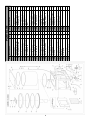
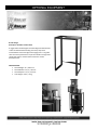
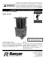
PLEASE READ THE ENTIRE CONTENTS OF THIS MANUAL PRIOR TO
INSTALLATION AND OPERATION. BY PROCEEDING YOU AGREE THAT
YOU FULLY UNDERSTAND AND COMPREHEND THE FULL CONTENTS OF
THIS MANUAL. FORWARD THIS MANUAL TO ALL OPERATORS. FAILURE TO
OPERATE THIS EQUIPMENT AS DIRECTED MAY CAUSE INJURY OR DEATH.
REV A 05-20-09
ASSEMBLY AND OPERATION MANUAL
OIL FILTER / CAN CRUSHER
MODEL: RP-20FC
Keep this operation manual near the
machine at all times. Make sure that
ALL USERS read this manual.
SHIPPING DAMAGE CLAIMS
When this equipment is shipped, title passes to the
purchaser upon receipt from the carrier. Consequently,
claims for the material damaged in shipment must be
made by the purchaser against the transportation
company at the time shipment is received.
BE SAFE
Your new Oil Filter/ Can Crusher was designed and
built with safety in mind. However, your overall safety
can be increased by proper training and thoughtful
operation on the part of the operator.
DO NOT operate or repair this equipment without
reading this manual and the important safety
instructions shown inside.
1645 Lemonwood Dr.
Santa Paula, CA. 93060, USA
Toll Free 1-800-253-2363
Tel: 1-805-933-9970
Fax: 1-805-933-9160
www.rangerproducts.com
RP -20FC
OIL FILTER / CAN CRUSHER
WARRANTY POLICY
Ranger Products™ are backed by over 35 years of manufacturing experience. Every Oil Filter / Can Crusher bearing
the Ranger™ name is sold with the following warranty.
•
Each Ranger Product™ is warranted to be free from defects in workmanship and material for a period of one
year from the date of shipment provided that a written claim for such defect is made within that time.
•
This warranty does not cover damage or defects caused by carelessness of the operator, misuse, abuse or
abnormal use which in any way impairs the proper functioning of the equipment or by the use or addition of
parts not manufactured by Ranger Products™ or its suppliers.
THIS WARRANTY IS EXPRESSLY MADE IN LIEU OF ANY AND ALL OTHER WARRANTIES EXPRESSED OR
IMPLIED INCLUDING THE WARRANTIES OF MERCHANTABILITY AND FITNESS OR A PARTICULAR PURPOSE.
If your Ranger Products™ machine is not functioning properly, call your Ranger Products™ dealer immediately. On
some occasions, an independent contractor may be hired to do the repairs. Within the warranty period, a customer
should not hire his own contractor unless it is authorized in writing by Ranger Products™.
If it is necessary to return equipment for repairs, your dealer will so advise you. When returning equipment for repairs,
see that machines are properly crated and protected, and prepay transportation.
Defective parts replaced at no charge must be returned to your dealer or Ranger Products™ within 60 days of the date
that the replacement parts are shipped; otherwise, you must pay for the replacement parts at the current selling price.
OPERATOR PROTECTIVE
EQUIPMENT
Personal protective equipment helps keep equipment use
safer. However, equipment does not take the place of safe
operating practices. Always wear durable work clothing.
Shop aprons or shop coats may also be worn, however
loose fitting clothing should be avoided. Tight fitting
leather gloves are recommended to protect operators.
Sturdy leather work shoes with steel toes and oil resistant
soles should be used by personnel to help prevent injury
in typical shop activities.
OWNER’S RESPONSIBILITY
To maintain machine and user safety, the responsibility of
the owner is to read and follow these instructions:
Follow all installation instructions.
Make sure installation conforms to all applicable
Local, State, and Federal Codes, Rules, and
Regulations; such as State and Federal OSHA
Regulations and Electrical Codes.
Carefully check the unit for correct initial function.
Read and follow the safety instructions. Keep them
readily available for machine operators.
Make certain all operators are properly trained, know
how to safely and correctly operate the unit, and are
properly supervised.
Allow unit operation only with all parts in place and
operating safely.
Carefully inspect the unit on a regular basis and
perform all maintenance as required.
Service and maintain the unit only with authorized or
approved replacement parts.
Keep all instructions permanently with the unit and
all decal’s on the unit clean and visible.
Eye protection is essential during installation and
operation. Safety glasses with side shields,
goggles, or face shields are acceptable.
Back belts provide support during lifting
activities and are also helpful in providing
operator protection. Consideration should
also be given to the use of hearing protection if activity
is performed in an enclosed area, or if noise levels are
high.
2
IMPORTANT SAFETY INSTRUCTIONS
Do not attempt to crush aerosol cans, cylinders of
compressed gas, fuel filters, or containers of
flammable liquids or solvents.
MAKE SURE TO READ AND UNDERSTAND
ALL INSTRUCTIONS AND SAFETY
PRECAUTIONS AS OUTLINED IN THE
MANUFACTURER’S SERVICE MANUAL
PRIOR TO USING THIS EQUIPMENT.
Do not alter or modify any part of this equipment.
Always wear suitable industrial gloves when
handling crushed objects to prevent injury.
FAILURE TO FOLLOW THESE
INSTRUCTIONS CAN RESULT IN
DEATH OR BODILY HARM TO OPERATOR
AND/OR BYSTANDERS
Do not stack filters or cans inside the crushing
chamber.
DO NOT open the door while the unit is
operating. Always wait for the press to cycle
completely.
Never exceed the recommended 125 to 175 PSI
working pressure.
Clear up any spilled oil immediately so it will
not cause a slipping hazard.
Keep the crusher out of reach of children and
other untrained persons. This press is dangerous
in the hands of untrained users.
Keep the work area clean and well lighted.
Cluttered benches and dark areas increase
the risks of injury to persons.
Do not install this press on any asphalt or wood
surface. Make sure the press is firmly
secured to a dry, oil/grease free, flat, level,
concrete surface.
Prior to using the press, make sure all debris
and/or tools are removed from inside the press
bed area.
Dress properly. Do not wear loose clothing or
jewelry. Contain long hair. Keep hair,
clothing, and gloves away from moving parts.
Loose clothes, jewelry, or long hair increases
the risk of injury to persons as a result of
being caught in moving parts.
Once contact between the press head and the
filter/can has been made, step away as far as
possible and continue to slowly apply pressure
until the procedure is completed.
Never leave the press in a loaded pressing-down
condition. Once the crushing job has been
completed, immediately retract the press head
then switch the operation lever on the
valve body to the neutral/off position.
Always wear eye protection. Wear ANSI
approved safety goggles.
Stay alert. Watch what you are doing and use
common sense when operating the press. Do
not use the press while tired or under the
influence of drugs, alcohol, or medication.
A moment of inattention while operating the
press increases the risk of injury to persons.
Never attempt to remove a filter or paint can that
has become stuck in the moving parts of the
press while it is connected to its air
supply source.
Always keep your hands, fingers or other body
parts safely away from the crushing head
during operation.
Avoid unintentional starting. Be sure the
operation lever on the valve body is positioned
to the neutral/off position before connecting to
the air supply.
Do not overreach. Keep proper footing and
balance at all times. Proper footing and balance
enables better control of the press.
Check crusher regularly for proper operation and
repair or replace worn or damaged parts
immediately. If the crusher appears to be
damaged in any way, is badly worn, or operates
abnormally it must be removed from use until
repairs are made. Use only manufacturer’s
approved accessories and service parts.
Do not smoke when operating this unit and do not
operate this unit when someone else in the
vicinity is smoking.
Do not operate the crusher in explosive
atmospheres, such as in the presence of
flammable liquids, gases, or dust.
The press is able to create sparks resulting in
the ignition of the dust or fumes.
Never attempt to service this unit while it is
connected to its air supply source.
3
TOOLS / SUPPLIES REQUIRED
MAINTENANCE
Adjustable wrench or metric open end/combination
wrenches, Teflon tape, hammer, drill and bit.
Quick disconnect Air fitting to match your air source.
Bolts and or anchors.
Keep the press clean and free of debris and dirt.
All exposed machine surfaces of the press
should be brushed clean and wiped with WD-40 or
equivalent.
UNPACKING INSTRUCTIONS
Regularly check the air lubricator and water filter for
water - drain as required.
1. Use caution when unbolting or unstrapping from
shipping pallet. Components are heavy and may have
shifted during shipping.
Regularly clean the press chamber to remove any
accumulated sludge, metal particles or other debris that
could affect the press operation.
ASSEMBLY INSTRUCTIONS
Check drain hose for accumulation of debris, and
remove any materials that may be clogging the hose.
1. Set the unit on a sturdy bench or table that can
support its weight and has provisions for the drain hose
and room for an approved waste oil container below the
crusher.
(Optional Ranger Oil Filter Crusher Stand is available from
your Authorized Ranger Products Dealer. See page 9.)
Inspect for leaks and drain the approved Waist Oil
Container in accordance with Local, State and Federal
regulations.
2. Bolt or lag screw (not provided) the unit to the stand or
table.
Apply motor oil to door latch pivot points on a regular
basis to prevent latch from binding.
Apply grease to door hinges on a regular basis to
prevent the door from binding.
3. Thread an appropriate fitting for your air supply into
the air oil regulator. Use teflon tape on the threads.
AN AIR LINE DRYER MUST BE USED ON THE AIR
SUPPLY LINE. FAILURE TO DO SO WILL VOID
WARRANTY AND DAMAGE AIR CYLINDER,
VALVES AND FITTINGS.
4. Connect air supply line using 1/4 inch air hose with
125 -175 p.s.i. maximum.
5. Ensure the drain hose is connected and an approved
waste oil container is in place below the crusher before
proceeding.
TECHNICAL SPECIFICATIONS
• Overall Height: 29 1/2” / 749 mm.
• Chamber Opening Depth: 11” / 279 mm.
• Overall Width: 17” / 432 mm.
• Average cycle time: 15-20 seconds
• Overall Depth: 17” / 432 mm.
• Air input: 125-175 PSI
• Chamber Opening Height: 10.25” / 260 mm.
• Unit Weight: 228 lbs. / 103 kg.
• Chamber Opening Width: 8.25” / 209 mm.
4
WARNING!
WARNING!
The brass components of this product contain lead,
a chemical known to the State of California to cause
birth defects (or other reproductive harm).
Avoid off-center loads. If the press seems to be
laboring more than usual or the filter/can is
unusually hard to press, immediately stop operation.
Disconnect the press from its air supply source, and
inspect or adjust the filter/canto eliminate or diminish
an off-center loading condition. Do not operate the
press if the filter/canto tilts or binds during the down
movement of the press head.
OPERATION
WARNING!
WARNING!
Prior to operation a visual inspection shall be made.
Check press for leaks, worn or missing parts.
Any press that appears to be damaged in any way, is
badly worn, or operates abnormally must be removed
from use until repairs are made. Contact a factory
authorized service center for repair or maintenance
of the press.
Never leave the press in a loaded pressing-down
condition. Once the crushing job has been
completed, immediately retract the press head then
switch the operation lever on the valve body to the
neutral/off position.
7. To remove the crushed filter/can, position the knob
on the control valve right (counterclockwise). The air will
exhaust from the press cylinder and the press head will
rise.
1. Connect air supply to the air connection fitting. Turn
the external air supply on.
2. Open the door and place empty filter in the center of
chamber with the open end down.
8. Open the door to remove the filter/can from the press
chamber.
3. Close the door and latch it firmly.
Important Note: The door must be closed, to activate
control valve.
WARNING!
WARNING!
Never attempt to remove a filter or paint can that has
become stuck in the moving parts of the press while
it is connected to its air supply source.
DO NOT open the door while the unit is operating.
Always wait for the press to cycle completely.
4. Position the knob on the control valve left (clockwise)
to begin press operation.
9. Place the control valve in “Off” (middle) position when
the unit is not in use.
5.The press head will descend to crush the filter/can.
6. Once contact between the press head and the filter/
can has been made, step away as far as possible and
continue to slowly apply pressure until the procedure is
completed.
5
6
1
6
Air Switch Rod
Air Switch
Screw M4*22
Air Pipe 2# (8*235mm)
Screw M5*30
Muffle (1/4")
Air Pipe 3# (8*250mm)
Air Pipe 4# (8*220mm)
Quick Vent Valve
Muffle (3/8")
Air Pipe 5# (8*500mm)
Drain Hose
Clamp
Crusher Plate Assy.
Washer M4
Nut M4
Plexiglass
Door Assy.
Screw M4 x 10
8
9
10
11
12
13
14
15
16
17
18
19
20
21
22
23
24
25
4
1
1
4
4
1
1
1
1
1
1
1
1
1
2
1
1
1
9
2
7
Screw M5 x 10
4
6
Connector (1/4")
Spring Washer M5
3
1
Air Pipe 1# (8*280mm)
Regulator with Filter
2
1
5
Connection
1
Qty
6
Description
Item
50
49
48
47
46
45
44
43
42
41
40
39
38
37
36
35
34
33
32
31
30
29
28
27
26
Control Valve
Connector (1/4")
Safety Valve
Upper Cover Assy.
Air Cylinder
Bolt M10 x 22
Spring Washer 10
Plate Assy.
Seal Ring 310
Guiding Ring
O-Ring 300 x 5
Piston Rod Assy.
Spring Washer M12
Washer M12
Bar
Nut M12
O-Ring 300 x 3.1
O-Ring 60 x 3.1
Guiding Ring
Support Frame Assy.
Lock Assy.
Item Description
PARTS LIST
1
1
1
1
1
1
1
1
1
1
1
1
8
8
8
16
2
1
1
1
1
Qty
OPTIONAL EQUIPMENT
Brand:Ranger
Description:OilFilterCrusherStand
AruggedmetalstanddesignedtofittheRangerRPͲ20FCoilfilter
crusherforefficientfluidhandling.Theheavydutystand
accommodatesusedoilstoragetanksrangingfrom5Ͳ55Ͳgallon
sizesevenwhenpositionedontopofdrumdollies.Storagetanks
simplyslideundertoreceivewasteoilfromthecrusher
downspouttube.
SPECIFICATIONS
x OverallHeight:42”/1067mm.
x OverallWidth:27Ͳ3/4”/705mm.
x OverallDepth:17Ͳ3/4”/451mm.
x UnitWeight:72lbs./33kg.
7
For Parts Or Service
Contact:
BendPak Inc. / Ranger Products
1645 Lemonwood Dr.
Santa Paula, CA. 93060
Tel: 1-805-933-9970
Toll Free: 1-800-253-2363
Fax: 1-805-933-9160
www.bendpak.com
www.rangerproducts.com