1
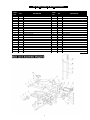
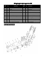
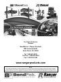
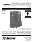
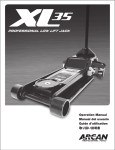
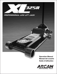
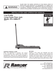
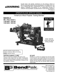
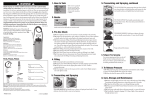
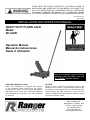
PLEASE READ THE ENTIRE CONTENTS OF THIS MANUAL PRIOR TO INSTALLATION AND OPERATION. BY PROCEEDING YOU AGREE THAT YOU FULLY UNDERSTAND AND COMPREHEND THE FULL CONTENTS OF THIS MANUAL. FORWARD THIS MANUAL TO ALL OPERATORS. FAILURE TO USE THIS EQUIPMENT AS DIRECTED MAY CAUSE INJURY OR DEATH. REV B 03-04-2015 P/N 5150446 INSTALLATION AND OPERATION MANUAL HEAVY DUTY FLOOR JACK Model: RFJ-6HD Operation Manual Manual de Instrucciones Guide d’ Utilisation Keep this operation manual near the machine at all times. Make sure that ALL USERS read this manual. SHIPPING DAMAGE CLAIMS When this equipment is shipped, title passes to the purchaser upon receipt from the carrier. Consequently, claims for the material damaged in shipment must be made by the purchaser against the transportation company at the time shipment is received. BE SAFE Ranger™ Floor Jacks are designed and built with safety in mind. However, proper training and thoughtful operation on the part of the user can increase your overall safety. DO NOT operate or repair this tool without reading this manual and the important safety instructions shown inside. 1645 Lemonwood Dr. Santa Paula, CA. 93060, USA Toll Free: 1-800-253-2363 Tel: 1-805-933-9970 Fax: 1-805-933-9160 www.rangerproducts.com LAS INSTRUCCIONES EN ESPAÑOL EMPIEZAN EN LA PÁGINA 7. LES DIRECTIVES EN FRANÇAIS COMMENCEMENT À LA PAGE 10. THIS OPERATING MANUAL CONTAINS IMPORTANT DETAILS CONCERNING THE SAFE OPERATION OF THIS TOOL THE USER MUST READ AND UNDERSTAND THESE DETAILS BEFORE ANY USE OF THE TOOL. THIS MANUAL MUST BE RETAINED FOR FUTURE REFERENCE. ALTERATIONS Because of potential hazards associated with this type of equipment, no alterations shall be made to the product. OWNER/OPERATOR RESPONSIBILITY: FOR YOUR SAFETY AND TO PREVENT INJURY: The owner and/or operator shall study the product instructions and retain them for future reference. Use Service Jack for lifting purposes ONLY. Always support vehicle with jack stands. The owner and/or operator shall have an understanding of the product operating instructions and warnings before operating the jack. Warning information shall be emphasized and understood. If the operator is not fluent in English, the product instructions and warnings shall be read to and discussed with the operator in the operator’s native language by the purchaser/ owner or his designee, making sure that the operator comprehends its contents. THIS IS A LIFTING DEVICE ONLY. DO NOT MOVE OR DOLLY THE VEHICLE WHILE ON THE JACK. IMMEDIATELY AFTER LIFTING, SUPPORT THE VEHICLE WITH APPROPRIATE MEANS. DO NOT EXCEED RATED CAPACITY. OVERLOADING CAN CAUSE DAMAGE TO OR FAILURE OF THE JACK. LIFT ONLY ON AREAS OF THE VEHICLE AS SPECIFIED BY THE VEHICLE MANUFACTURER. INSPECTION CENTER LOAD ON SADDLE PRIOR TO LIFTING. OFF-CENTER LOADS MAY CAUSE DAMAGE TO JACK, LOSS OF LOAD, PROPERTY DAMAGE, PERSONAL OR FATAL INJURY. Visual inspection should be made before each use of the jack. This inspection should check for abnormal conditions such as cracked welds, leaks, and damaged, loose or missing parts. THIS JACK IS DESIGNED FOR USE ONLY ON HARD LEVEL SURFACES CAPABLE OF SUSTAINING THE LOAD. USE ON OTHER THAN HARD LEVEL SURFACES CAN RESULT IN JACK INSTABILITY AND POSSIBLE LOSS OF LOAD. Any jack that appears to be damaged in any way, is found to be worn or operated abnormally, must be removed from service immediately. Any jack that operates abnormally shall be removed from service until repaired by a qualified repair service center. NO ALTERATIONS TO THE JACK SHALL BE MADE. READ, STUDY AND UNDERSTAND THE OPERATING MANUAL PACKED WITH THIS JACK BEFORE OPERATING. If the jack is accidentally subjected to an abnormal load or shock, it must be taken out of service immediately and be inspected by a qualified repair or service center. FAILURE TO HEED THESE WARNINGS MAY RESULT IN LOSS OF LOAD, DAMAGE TO JACK, AND/OR FAILURE RESULTING IN PROPERTY DAMAGE, PERSONAL OR FATAL INJURY. It is recommended that an annual inspection is performed on the jack and that any damaged or worn parts, decals or warning labels be replaced with manufacturer’s specified parts. 2 ASSEMBLY INSTRUCTIONS 2. To lower load: Re-check to make sure release valve is tightly closed. Then, operate the jack handle until the load is raised enough to remove the jack stands. 1. Remove 2-piece handle from box. Insert narrow portion of top section (17) into bottom section (15) and secure with bolt (16) provided. 2. Then, slightly press down on the handle yoke assembly to release pressure on the handle yoke assembly retainer and remove retainer. This will allow handle yoke to be raised to operating position. DO NOT CRAWL UNDER VEHICLE WHILE LIFTING VEHICLE OR REMOVING THE JACK STANDS! Once jack stands are removed, open release valve very slowly to lower the vehicle. Lower jack completely so that the vehicle is securely resting on the ground and that jack no longer makes contact with vehicle. 3. Grease handle receptacle and insert slotted end of handle into place. Tighten set screw (13) to secure handle. OPERATING INSTRUCTIONS BEFORE USE: Air may become trapped in the hydraulic system during transit. To purge air: 1. Open release valve by turning handle counterclockwise. Keep hands or feet away from the hinge mechanism of the jack. 2. Pump handle rapidly 4 full strokes. This will expel air that may have entered oil passages during transit. MAINTENANCE When adding or replacing hydraulic fluid, always use a quality hydraulic fluid. DO NOT use brake fluid, alcohol, detergent motor oil, dirty oil or any fluid other than quality hydraulic fluid. Improper fluids can cause internal damage to the jack and improper or unsafe operation. 3. Close release valve by rotating handle clockwise and pump handle. 4. If lift arm is raised, jack is ready for use. If not, repeat this procedure. Adding Hydraulic Fluid IMPORTANT: With the saddle fully lowered and the jack on level ground, remove the filler screw. Hydraulic fluid should be filled to the level of the filler screw hole. If the level is below this hole, add hydraulic fluid as needed. Before attempting to raise any vehicle, check vehicle service manual for recommended lifting surfaces. OPERATION: LUBRICATION All moving joints require lubrication often. Lightly grease saddle post and saddle bottom. Remove handle and grease the lower end of handle where it rotates in the handle socket. Using a grease gun, grease the lift arm pivot shaft grease fitting until grease appears at the end of the shaft. Oil all lift arm linkages, front wheels and rear casters. 1. To Raise Load: Close release valve tightly (by turning handle clockwise). DO NOT OVERTIGHTEN. Position jack under load so that saddle will contact load firmly and load is centered so it cannot slip. Operate jack handle until saddle approaches the load. Once again, check to see that saddle is correctly positioned. Raise load to desired height. Place jack stands of appropriate capacity under the vehicle. DO NOT CRAWL UNDER VEHICLE WHILE LIFTING VEHICLE OR PLACING OR REMOVING JACK STANDS! SPECIFICATIONS Rated Load Capacity: 3 Tons (2722 kg.) Minimum Height: 3-1/2” (90mm) High height 21” (533mm) Overall length 27” (686mm) Width 14” (356mm) Shipping Weight 108 lbs / 50kg Strokes to Full Height 8 (without load) Place jack stands at vehicle manufacturer’s recommended lift areas that provide stable support for the raised Vehicle. Once jack stands are positioned, open the release valve VERY SLOWLY (by turning the handle counterclockwise). Lower the load to rest on the jack stands. Then, make sure that the release valve on the jack is closed tightly (by turning the handle clockwise). 3 FEATURES Low profile chassis accommodates low ground clearance vehicles. Swivel Casters for easy mobility “Quick-pump” feature for fater lifting speed. Professional model designed for heavy use. Universal-joint, pressure release system. Roller-cam, dual plunger pump assembly. Heavy steel construction for maximum durability. Double-sealed hydraulics for longer service life. Sealed hydraulic unit prevents contamination. Safety-overload system. Flanged side plates for increased strength. TROUBLESHOOTING PROBLEM ACTION 1. Unit will not lift load Purge air from hydraulic system by following procedure under OPERATING INSTRUCTIONS. 2. Unit will not sustain load or feels “spongy” under load. Purge air from hydraulic system as above. 3. Unit will not lift to full height. Purge air from hydraulic system as above. Check to be sure oil level is not too high or low. 4. Unit will not lower completely. Check oil level. Make sure not overfilled. 5. Handle tends to raise up while the unit is under load. Pump the handle rapidly several times to push oil past ball valves in power unit. 6. Unit still does not operate. Contact Parts & Warranty Department. WARRANTY WARRANTY NOTICE This Floor Jack from Ranger Products™ is covered under a 1 year warranty when used as recommended. Many parts are available, as shown in parts breakdown on pages: 5 - 6. For assistance with the operation or the availability of replacement parts contact our Customer Service Department at 1-800-253-2363. Please have available a copy of your receipt, the model number of the product, and specific details regarding your question. WARRANTY INFORMATION We want to know if you have any cooncerns with Ranger Products. If so, please call us toll-free for immediate assistance: 1-800-879-7316 or 1-805-933-9970 For more information about our warranty, please visit: www.bendpak.com/support/warranty 4 RFJ-6HD PARTS BREAKDOWN Main Jack Assembly Parts Lists PART NO. QTY 1 2 3 4 5 6 7 8 9 10 11 12 13 14 15 16 17 18 19 20 21 2 2 2 1 2 2 1 3 1 1 1 1 2 1 2 1 2 1 1 1 3 DESCRIPTION M20 Hex Nut M20 Washer Front Wheel Left Shaft Unit M18 Hex Nut Rod Link Spindle Front M30 Hex Nut Lifting Arm Saddle Grease Nipple Block Link Return Spring Power Unit Pin, Link Rod M4x40 Cotter Pin M18 Split Lock Washer Bolt Handle Socket M12 Handle Bolt M12 Hex Nut Main Jack Assembly Diagram 5 Page 2 of 9 PART NO. QTY 22 23 24 25 26 27 28 29 30 31 32 33 34 35 36 37 38 39 40 41 3 1 1 1 2 2 1 1 2 2 2 1 2 2 1 1 2 1 1 2 DESCRIPTION M12 Washer Plunger Pin Clasp M12x60 Bolt M16 Washer M16 Hex Nut Spindle Rear Bolt M12x25 Inner Hex Bolt M12x25 Hex Bolt Rear Wheel Pull Rod M10 Washer M10 Hex Nut Lower Handle Upper Handle M6x35 Hex Nut Handle Grip Cover M25 Hex Nut Power Unit Assembly RFJ-6HD PARTS BREAKDOWN PART NO. QTY 1 2 3 4 5 6 7 8 9 10 11 12 13 14 15 16 17 18 1 1 1 1 1 1 1 1 1 1 1 2 1 5 2 1 2 2 DESCRIPTION Top Nut O. Ring Overlay Oil Reservoir Oil Plug Underlay Piston Rod Bowl Washer Gasket Ring Oil Cylinder Oil Cylinder Gasket Ring Filter Screen Valve Body M5 Steel Ball Copper Seal Ring Pump Cylinder (Big) Pump Cylinder Gasket Ring (Big) Pump Cylinder Nylon Ring (Big) PART NO. QTY 19 20 21 22 23 24 25 26 27 28 29 30 31 32 33 34 35 36 1 1 1 1 1 2 2 1 2 1 1 1 1 2 2 2 2 2 Power Unit Assembly Friday, 8:00am to 4:30pm PST 6 Page 3 of 9 DESCRIPTION Pump Core (Big) M6 Steel Ball Gasket Ring Release Valve Pump Cylinder (Small) Pump Cylinder Gasket Ring (Small) Pump Cylinder Nylon Ring (Small) Pump Core (Small) Compression Springs Gasket for Cylinder Cover (Big) Gasket for Cylinder Cover (Small) Bead Ring (Big) Bead Ring (Small) Ball Vale Seat High Compression Spring Pressure Adjusting Screw Safety Valve Gasket Ring Safety Valve Bolt advertencia dañada o desgastada sean reemplazadas con las refacciones indicadas del fabricante. ESTE MANUAL DE INSTRUCCIONES CONTIENE DETALLES IMPORTANTES RESPECTO AL OPERACIÓN SEGURA DE ESTA HERRAMIENTA. EL USUARIO DEBE LEER Y COMPRENDER TODOS ESTOS DETALLES ANTES DE EMPLEAR ESTE EQUIPO. ESTE DOCUMENTO DEBE SER GUARDADO PARA REFERENCIA FUTURA. ALTERACIONES Debido a los peligros potenciales asociados con este tipo de equipo, no se hará ninguna alteración al producto. PARA SU SEGURIDAD Y PARA PREVENIR LESIONES: Emplee el gato SOLO para levantamiento. Siempre soporte el vehículo con el pedestal del gato. RESPONSABILIDAD DEL DUEÑO U OPERADOR: El dueño y/u operador deberá estudiar las instrucciones del producto y retenerlas para referencia futura. ESTA ES UNA HERRAMIENTA DE LEVANTAMIENTO SOLAMENTE. NO MUEVA O SACUDA EL VEHÍCULO MIENTRAS ESTÉ SUSPENDIDO POR EL GATO HIDRAULICO. INMEDIATAMENTE DESPUÉS DE LEVANTAR EL VEHÍCULO. El dueño y/u operador deberá tener una comprensión completa de las instrucciones y de las advertencias sobre la operación del producto antes de operar el gato de piso. SOPÓRTELO CON LOS MEDIOS APROPIADOS. NO EXCEDA LA CAPACIDAD INDICADA DEL GATO. LAS SOBRECARGAS PUEDEN OCASIONAR DAÑOS O EL DISFUNCIONAMIENTO DEL GATO DE PISO. LEVANTE SOLO LAS ÁREAS DEL VEHÍCULO ESPECIFICADOS POR EL FABRICANTE DEL VEHÍCULO. CENTRA LA CARGA EN LA SILLA ANTES DE LEVANTAR EL OBJETO. CARGAS NO CENTRADAS PUEDEN OCASIONAR DAÑO AL GATO. La información sobre el cuidado del uso debe ser enfatizada y comprendidad. Si el operador no habla fluídamente el idioma Inglés, el comprador/dueño leerá y discutirá las instrucciones y advertencias relacionadas a este artículo de trabajador con el operador en su idioma natal y así se asegurará que él comprenda el contenido. PÉRDIDA DE LA CARGA, DAÑOS PERSONALES O LESIONES FATALES. ESTE EQUIPO ESTÁ DISEÑADO SOLAMENTE PARA EL USO EN SUPERFICIES DURAS Y PLANAS, CAPACES DE SOSTENER LA CARGA. EL USO EN CUALQUIER OTRO TIPO DE SUPERFICIE PUEDE RESULTAR EN LA INESTABILIDAD DEL GATO Y LA POSIBLE PÉRDIDA DE LA CARGA. NO SE DEBERÁ HACER NINGUNA ALTERACIÓN AL GATO. ANTES DE OPERAR ESTE EQUIPO LEA, ESTUDIE Y COMPRENDA EL MANUAL DE OPERACIÓN INCLUÍDO CON ÉL. INSPECCIÓN Una inspección visual se deberá llevar a cabo antes de usar el gato de piso. Esta inspección debe incluir la revisión de condicionaes anormales, tales como soldaduras rajadas, agujeros y piezas dañadas, sueltas o extraviadas. Cualquier gato de piso que aparenta tener daños de cualquier manera, o que se encuentra desgastado o empleado de manera inapropiada, anormal, debe dejar de ser utilizado inmediatamente. LA NEGLIGENCIA DE RESPETAR ESTAS ADVERTENCIAS PUEDE OCASIONAR LA PÉRDIDA DE LA CARGA, DAÑO AL GATO Y/O DISFUNCIONAMIENTO DEL MISMO, RESULTANDO EN DAÑOS DE PROPIEDAD PERSONALES E INCLUSO LESIONES FATALES. Cualquier gato de piso que no funciona como debería, tiene que ser quitado de servicio hasta ser reparado por un centro calificado de servicio de reparación. Se recomienda que se lleve a cabo una inspección anual del gato y que cualquier pieza o calcomanía de 7 INSTRUCCIONES DE ENSAMBLAJE Baje la carga hasta que esté mantenida por los pedestales del gato. Después, cerciorar que la válvula de presión del gato esté bien cerrada (al girar el mango en el sentido de las aguajs del reloj). 1.Quite el mango de dos piezas de la caja. Inserte la sección estrecha de la parte superior (17) en la sección inferior (15) y fíjelo con el tornillo (16) incluído. 2. A continuación, presione ligeramente hacia abajo el yugo de montaje. Para liberar la presión del yugo remueva el bloque de retención. Esto permitirá que el mango pueda ser levantado hasta estar en posición de operación. 3. Engrase el receptáculo del yugo e inserte la punta muescada del mango en su lugar. Asegure con el juego de tornillos (13) para fijar el mango. 2. Para bajar la carga: Revise nuevamente para asegurarse que la la válvula de presión esté bien cerrada. Luego, opere el mango del gato hasta que la carga esté suficientemente levantada para quitar los pedestales del gato. INSTRUCCIONES DE OPERACIÓN NO SE META DEBAJO DEL VEHÍCULO MIENTRAS LO ESTÉ LEVANTANDO O MIENTRAS SE QUITEN LOS PEDESTALES DEL GATO ANTES DE USARSE: Aire puede ser atrapado en el sistema hidráulico durante la transportación/tránsito. Para expulsar el aire: Una vez que se hayan quitado los pedestales, abra muy lentamente la válvula de presión para bajar el vehículo. Baje el gato completamente para que el vehículo esté seguro en el piso y para que el gato ya no tenga contacto con el vehículo. . 1. Abra la válvula de presión al girarla contra el sentido de las agujas del reloj. 2. Suba y baje el mango rápidamente cuatro extensiones completas. Esto expulsará el aire que pueda haber entrado a los conductos de aceite durante el tránsito. 3. Cierre la válvula de presión al girar el mango en el sentido de las agujas del reloj y suba y baje el mango. 4. Si se levanta el brazo, el gato de piso está listo para utilizarse. Si no, repita este procedimiento. Mantenga alejados los brazos y los pies del mecanismo de bisagra del gato. IMPORTANTE: Antes de intentar levantar cualquier vehículo, revise el manual de servicio del vehículo para averigüar los superficies recomendadas para el levantamiento. MANTENIMIENTO Cuando se agrega o reemplaza el líquido hidráulico, siempre utilice un líquido de calidad. NO USE líquido de frenos, alcohol, aceite detergente del motor, aceite sucio o cualquier otro líquido que no sea de calidad hidráulico. Líquidos no adecuados pueden ocasionar daños internos al gato u operaciones riesgosas. OPERACIÓN: 1. Para levantar la carga: Cierra bien la válvula de expulsión al girarla en el sentido de las agujas del reloj. NO LA AJUSTE DEMASIADO FUERTE. Posicione el gato debajo de la carga para que la silla puede tener contacto firme con la carga y para que la carga esté bien centrada y no pueda caerse. Opera el mango del gato hasta que la silla se acerca a la carga. Nuevamente, revisa para asegurar que la silla esté correctamente posicionada. Levanta la carga hasta llegar a la altura deseada. Coloque los pedestales de la capacidad adecuada del gato debajo del vehículo. NO SE META DEBAJO DEL VEHÍCULO MIENTRAS LO LEVANTA O CUANDO ESTÉ COLOCANDO O QUITANDO LOS PEDESTALES DEL GATO. Para Agregar el Líquido Hidráulico: Con la silla completamente baja y el gato en una posición plana, quite el tapón del recipiente. El líquido hidráulico deberá llegar hasta el nivel del agujero del tapón del recipiente. Si el nivel del líquido está debajo del agujero, agregue el líquido necesario hasta que llegue al nivel recomendado. LUBRICACIÓN Todas las articulaciones requieren lubricación frecuente. Unte ligeramente el poste de la silla y la parte inferior de la silla. Quite el mango y engrase la parte inferior del mango donde hace rotación en el mango. Utilizando una pistola para el engrasamiento, engrase la pieza del eje pivotal del brazo de levantamiento hasta que la grasa salga de la punta del eje. Unte todas las conexiones del brazo de levantamiento, las ruedas delanteras y las ruedecillas traseras. Coloque los pedestales del gato en los puntos estratégicos de levantamiento recomendados por el fabricante, que proveen el apoyo estable para el vehículo mientras esté levantado. Una vez que los pedestales del gato hidráulico estén colocados abra MUY LENTAMENTE la válvula de expulsión (al girar el mango contra el sentido de las agujas del reloj). 8 ESPECIFICACIONES Capacidad de Carga: 6.000 libras (2722 kg) Mínima altura: 3.5 pulgadas (90mm) Máxima altura: 21” (533mm) Longitud total: 27” (686mm) Ancho total: 14” (356mm) Peso de embalaje: 108 lbs. (50kg) Recorrido hasta la altura máxima sin carga: 8 DIAGNÓSTICO DE PROBLEMAS PROBLEMA SOLUCIÓN 1. El equipo no levanta la carga. Expulse el aire del sistema hidráulico. Siga el procedimiento bajo: INSTRUCCIONES DE OPERACIÓN 2. El equipo no sostiene la carga o se siente el equipo con bastante aire. Expulse el aire del sistema hidráulico como se indica en la misma sección. 3. El equipo no levanta la carga hasta la altura normal. Expulse el aire del sistema hidráulico como se indica anteriormente. Revise que los niveles de aceite no estén ni altos ni bajos. 4. El equipo no se baja completamente. Revise el nivel de aceite. Asegure que no esté sobre el nivel de lleno. 5. El mango tiende a levantarse cuando hay carga. Suba y baje el mango rápidamente varias veces para empujar el aceite más allá de las válvulas en la unidad de energía. 6. El equipo aún no funciona. Contacte al Departamento de Servicio al Cliente, su número se menciona abajo. GARANTĺA NOTIFICACIÓN DE GARANTĺA Este gato de piso está cubierto con una garantía de duración de un año cuando se emplea de manera recomendada. Muchas refacciones están disponibles, como se muestra en la páginas de listado: 5-6. Para asistencia con operación u órdenes de partes, contacte al Departamento de Servicio al Cliente: 1-800-253-2363. Favor de tener disponible una copia del recibo de compra, número de modelo del equipo y preguntas detalladas. INFORMACIÓN DE GARANTĺA Quisiéramos saber si tiene alguna duda o necesita información de los equipos de la marca Ranger Products. Si es así, por favor llame a los números del Departamento de Servicio al Cliente: 1-800-253-2363 or 1-805-933-9970 Para más información de su garantía, por favor visite: www.bendpak.com/support/warranty 9 MODIFICATIONS CE GUIDE D’UTILISATION CONTIENT DES RENSEIGNEMENTS IMPORTANTS SERVANT À FAIRE FONCTIONNER CET OUTIL DE FAÇON SÉCURITAIRE. L’UTILISATEUR DOIT LIRE ET COMPRENDRE CES RENSEIGNEMENTS AVANT D’UTILISER L’OUTIL. CONSERVER CE GUIDE POUR DES RÉFÉRENCES FUTURES. À cause des dangers potentiels associés à ce type d’équipement, ne faire aucune modification sur ce produit. POUR VOTRE SÉCURITÉ ET POUR PRÉVENIR LES BLESSURES: Utiliser le cric roulant SEULEMENT à des fins De lavage. Toujours mettre des chandelles pour soutenir le poids d l’auto. RESPONSABILITÉ DU PROPRIÉTAIRE/UTILISATEUR : Le propriétaire et l’utilisateur doivent étudier les directives concernant le produit et les conserver pour y référer ultérieurement. Le propriétaire ou l’opérateur, doit comprendre parfaitement les instructions de fonctionnement du produit ainsi que les avertissements avant d’utiliser ce cric. Il faut mettre l’accent sur la diffusion et la compréhension des informations contenues dans les avertissements. Si l’opérateur ne parle pas couramment l’anglais, le propriétaire ou l’acheteur ou une autre personne désignée devrait lire et prendre le temps discuter avec lui et dans sa langue maternelle, les instructions et avertissements concernant le produit et s’assurer que l’opérateur comprend bien tout le contenu. C’EST UN DISPOSITIF DE LEVAGE SEULEMENT. NE PAS DÉPLACER LE VÉHICULE PENDANT QU’IL EST SUR LE CRIC. IMMÉDIATEMENT APRÈS AVOIR SOULEVÉ LE VÉHICULE, VEUILLEZ SOUTENIR LE VÉHICULE PAR DES MOYENS ADÉQUATS. NE PAS DÉPASSER LA CAPACITÉ NOMINALE. UNE SURCHARGE PEUT CAUSER UN MAUVAIS FONCTIONNEMENT OU ENDOMMAGER LE CRIC. SE SERVIR SEULEMENT DES SURFACES DE LEVAGES SPÉCIFIÉES PAR LE FABRICANT DU VÉHICULE. BIEN CENTRER LA CHARGE SUR LA SELLE AVANT DE LA SOULEVER. UNE CHARGE DÉCENTRÉE PEUT ENTRAÎNER UNE PERTE DE LA CHARGE, DES DOMMAGES AU CRIC ET DES DOMMAGES À LA PROPRIÉTÉ OU CAUSER DES BLESSURES GRAVES OU MORTELLES. INSPECTION Une vérification visuelle devrait être faite avant chaque utilisation du cric. Cette vérification devrait inclure une recherche de conditions anormales comme des soudures craquées, des fuites, des pièces manquantes, lâches ou endommagées. CE CRIC EST CONÇU POUR ÊTRE UTILISÉ SUR DES SURFACES SOLIDES ET AU NIVEAU, CAPABLES DE SUPPORTER LA CHARGE. L’UTILISATION SUR TOUTE AUTRE SURFACE PEUT ENTRAÎNER UNE INSTABILITÉ DU CRIC ET UNE POSSIBILITÉ DE PERTE DE LA CHARGE. NE FAIRE AUCUNE MODIFICATION DU CRIC. LIRE, ÉTUDIER ET COMPRENDRE LE GUIDE D’UTILISATION INCLUS AVEC LE CRIC AVANT DE L’UTILISER. Tout cric qui semble endommagé ou usé de quelque façon que ce soit, ou qui fonctionne anormalement, doit être remisé immédiatement. Tout cric qui ne fonctionne pas normalement doit être retiré de l’atelier jusqu’à ce que les réparations nécessaires soient faites par un atelier de service agrée. Si le cric est soumis accidentellement à un poids anormal, ou si il subi un choc, il doit être retiré immédiatement et être inspecté par un atelier de service agrée. L’OMISSION DE LIRE CES AVERTISSEMENTS PEUT ENTRAÎNER UNE PERTE DE LA CHARGE, DES DOMMAGES AU CRIC ET DES DOMMAGES À LA PROPRIÉTÉ OU CAUSER DES BLESSURES GRAVES OU MORTELLES. Une vérification annuelle du cric est aussi recommandée, ainsi que le remplacement des pièces défectueuses ou usées, des autocollants et étiquettes d’avertissement manquants par les pièces spécifiées par le fabricant. 10 SPÉCIFICATIONS Capacité nominale de charge: 3 tonnes (2722 kg) Espace de dégagement bas: 3.5” (90mm) Hauter maximale de levée: 21” (533mm) Longeueur hors tout: 27” (686mm) Largeur: 14” (356mm) Poids à l’expédition : 108 lbs. (50kg) Nombre de coups pour obtenir la hauteur maximale (san charge): 8 DÉPANNAGE PROBLÉME ACTION 1. Le cric ne soulève pas la charge. Purger l’air du système hydraulique en suivant la procédure décrite dans la section DIRECTIVES POUR LE FONCTIONNEMENT. 2. Le cric ne supporte pas la charge ou semble flexible sous la charge. Purger l’air du système hydraulique comme mentionné. 3. Ne se soulève pas à la hauteur maximale. Purger l’air du système hydraulique comme mentionné ci-dessus. Vérifier que le niveau d’huile n’est pas trop haut ou trop bas. 4. L’appareil ne descend pas complètement. Vérifier le niveau d’huile. S’assurer qu’il n’est pas trop plein. 5. La poignée a tendance à remonter pendant qu’il y a une charge sur l’appareil. Pomper la poignée plusieurs fois rapidement pour pousser l’huile pour qu’elle dépasse le clapet à bille de l’appareil. 6. L’appareil ne fonctionne toujours pas. Veuillez contacter le service de Pièces et de garantie énuméré ci-dessous. AVIS DE GARANTIE POLITIQUE DE GARANTIE Ce cric roulant est couvert par une garantie d’un an lorsqu’il est utilisé selon les recommandations. Plusieurs pièces de rechange sont offertes, consulter les pages 5-6 pour voir les pièces détachées. Pour obtenir de l’aide pour le fonctionnement ou connaître la disponibilité des pièces de remplacement, veuillez contacter notre service de Pièces et de garantie au:1-800-253-2363. Veuillez avoir en main une copie de votre facture, le numéro de modèle du produit, et les détails concernant votre question. INFORMATIONS SUR LA GARANTIE Nous souhaitons être avisé si vous avez des questions concernant nos produits. Veuillez nous appeler sans frais pour obtenir de l’aide rapidement. Ne pas téléphoner chex le détaillant où vous avez acheté le produit: 1-800-253-2363 or 1-805-933-9970 Pour plus d’informations au sujet de notre garantie, se il vous plaît visitez: www.bendpak.com/support/warranty 11 For Parts Or Service Contact: BendPak Inc. / Ranger Products 1645 Lemonwood Dr. Santa Paula, CA. 93060 Tel: 1-805-933-9970 Toll Free: 1-800-253-2363 Fax: 1-805-933-9160 www.rangerproducts.com NOTE: Every effort has been taken to ensure complete and accurate instructions have been included in this manual, however, possible product updates, revisions and or changes may have occurred since this printing. BendPak Ranger reserves the right to change specifications without incurring any obligation for equipment previously or subsequently sold. Not responsible for typographical errors. 12