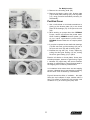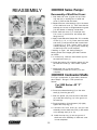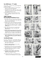
1
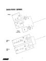
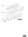
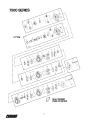
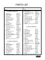
CONTENTS
Table of Content
Page
Wear, Checking parts for...................................................................................................3
Thrust Plates.....................................................................................................................3
Diverter Plates, Installing PERMCO...................................................................................3
Bearings; Checking for wear..............................................................................................3
Gear Housing, checking for wear.......................................................................................3
Covers, Shaft-end and port-end: Checking for wear...........................................................3
Types of PERMCO Pumps: Type I, II..................................................................................3
Exploded Views: PERMCO Pumps and parts..................................................................4-6
Parts numbers, PERMCO Pumps and Motors....................................................................7
Type I Pump: disassembly..................................................................................................8
reassembly...............................................................................................12
Type II Pump: disassembly.................................................................................................8
reassembly........................................................................................................12
Torques for reassembling, Table of...................................................................................15
Trouble Shooting; List of symptoms and cures.................................................................17
Motors, PERMCO Pumps used as ...................................................................................18
Parts, How to order PERMCO replacement; information needed......................................19
2
If you are rebuilding a Permco gear pump, you must
not install thrust plates of another make. Tolerances
and finishes on Permco parts are held closer than
those of other manufacturers of pump parts. For
warranty repairs under any circumstances, you
must not substitute other makes of parts in a
Permco pumps. USE ONLY GENUINE PERMCO
PARTS.
If you intend to rebuild a pump that has thrust plates
and you wish to replace the thrust plates with
Permco diverter plates, inspect the original port end
cover, shaft end cover, gear housing and bearing
carriers very carefully. To obtain the maximum
performance from diverter plates, all of the above
components must be in good condition with minimal
amount of wear. The following areas of wear are
the most critical. . and often overlooked:
You can successfully use Permco diverter plates to
rebuild other makes of pumps to obtain increased
operating pressures and pump life. However, read
the above paragraphs carefully.
1. Shaft end covers, port end covers, and bearing
carriers. . .Check bearing bores for out-of
roundness or elliptical shape. If more than 0.003"
out-of-round, do not use.
If you have any questions about rebuilding Permco
pumps or about using Permco parts to upgrade other
makes of pumps, call your local Permco pump and
parts distributor.
2. Gear housings... If the wear pattern on the
inlet side is in excess of 0.003" depth, do not
use.
3. Gears... Inspect very carefully. If you have
scored, scuffed or pitted journals, scratched or
scuffed tooth faces, deep nicks on tooth edges,
do not use; install new drive and driven gear.
4. Bearings... A loose fit between gear hub and
bearing ID may not mean a bad bearing. The
misalignment it can cause is detrimental to good
pump performance. We recommend installing a
complete set of new bearings at each rebuild.
TWO TYPES OF PUMPS
There are two types of Permco pumps as
determined by the configuration of the shaft end
covers... Type I & Type II. There are slight
differences in disassembly and reassembly
procedures, according to each shaft end cover. Also
Type II is normally shorter from front to back than
Type I. This is because no outboard bearing is used.
Be sure you know which type you are working on.
5. Seals. . .It is recommended that all seals be
replaced on any rebuild job.
CLEANLINESS IS HIGHLY IMPORTANT
Putting Permco diverter plates into a pump and
reusing the old worn parts will not necessarily
restore the pump to the high efficiency and
performance of a new Permco pump. Merely
installing new Permco diverter plates cannot restore
the pump to its original performance. Permco’s high
efficiency, performance, and life expectancy are
based on using all new PERMCO parts.
WARNING. Before you start disassembling the
pump, clean up your work bench. This will avoid
the headaches and danger of getting dirt, metal
fragments, and foreign objects into the fine-finished
cavities and threads of the pump and components,
and eventually into the entire hydraulic system. In
pump maintenance, extreme cleanliness is most
important.
3
PARTS LIST
Item No.
On
Drawing
Description
Part Number
3000 SERIES PUMPS/MOTORS
1
2
3
4
5
6
7
8
9
10
11
12
13
14
15
16
17
18
19
20
21
22
23
24
25
26
28
Snap Ring
Outboard Bearing
Double Lip Seal
Bearing Carrier
Seal Retainer
High Pressure Seal
Shaft End Cover (SEC)
Check Valve Assembly
Continental Shaft
Spacer
Snap Ring
Pump Shaft Seal
Motor Shaft Seal
Ring Seal
Crowned Roller Bearing
Thrust Plate (TP)
Teflon Coated Thrust Plate
Diverter Plate
Gasket Seal
Housing
Drive Shaft & Gear Set
Port End Cover
5/8" Grade 8 Washers
5/8-11 Grade 8 Threaded Rod
5/8-11 Grade 8 Hex Nut
Bearing Carrier
Connecting Shaft
Gear Set
Grade 8 Hex Head Cap Screw
W023-206
W58-39
W62-26-16
UA-0558-2
ZD-0558
W62-49-9
** - 0574- *
L-0280-K
** -0024
SA-0558
W86-100
W62-26-18
W62-49-11
KA-0558-1XS
X-0921
ZZ-0947
ZZ-0947-TC
ZZ-0947-DS
TA-2995-242
QZ-0577- ** - **
** -0024L- * - **
WZ-0592- *
W033-2
ZD-0391- ***
W3-65
** -0576- ** - ***
YZ-0022
U-0996L- **
W1- **
5000 SERIES PUMPS/MOTORS
1
2
3
4
5
6
7
8
9
12
13
14
15
Snap Ring
Outboard Bearing
Double Lip Shaft Seal
Bearing Spacer
Seal Retainer
High Pressure Seal
Shaft End Cover (SEC)
Check Valve Assembly
Continental Shaft
Pump Shaft Seal
Motor Shaft Seal
Ring Seal
Crowned Roller Bearing
W023-283
W58-47
W62-26-17
UA-0558-1
ZB-0558
W62-49-8
** -0574- *
L-0280-K
** -0024
W62-26-17
W62-49-8
MA-0558-1XS
R-0921
Item No.
On
Drawing
16
17
18
19
20
21
22
23
24
25
26
28
Description
Thrust Plate (TP)
Teflon Coated Thrust Plate
Diverter Plate
Bi-Rotational Diverter Plate
Gasket Seal
Housing
Drive Shaft & Gear Set
Port End Cover (PEC)
5/8" Grade 8 Washers
5/8-11 Grade 8 Threaded Rod
5/8-11 Grade 8 Hex Nut
Bearing Carrier
Connecting Shaft
Gear Set
Grade 8 Hex Head Cap Screw
Part Number
X-0947
X-0947-TC
X-0947-DS
X-0947-BRD
TA-2995-244
LZ-0577- ** - **
** -0024L- * - **
YZ-0592- *
W033-2
ZD-0391- ***
W3-65
** -0576- ** - ***
XZ-0022
LZ-0995L- **
W1- **
7500 SERIES PUMPS/MOTORS
1
2
3
4
5
6
7
8
9
10
11
14
15
16
17
18
19
20
21
22
23
24
25
26
27
28
7
Snap Ring
Outboard Bearing
Double Lip Seal
Bearing Spacer
Seal Retainer
High Pressure Seal
Shaft End Cover (SEC)
Check Valve Assembly
Continental Shaft
Spacer
Snap Ring
Ring Seal
Crowned Roller Bearing
Teflon Coated Thrust Plate
Diverter Plate
Bi-Rotational Diverter Plate
Gasket Seal
Housing
Drive Shaft & Gear Set
Port End Cover (PEC)
5/8" Grade 8 Washers
5/8-11 Grade 8 Threaded Rod
5/8-11 Grade 8 Hex Nut
Bearing Carrier
Connecting Shaft
Gear Set
O-Ring
Grade 8 Hex Head Cap Screw
W85-315
W58-48
W62-26-10
UA-0558
QZ-0961
W62-49-1
** -0574- *
L-0280-K
** -0024
ZE-0558
W86-137
VA-0558-1XS
Q-0921
AZ-0947
AZ-0947-DS
AZ-0947-BRD
TA-2995-252
RZ-0577- ** - **
** -0024L- * - **
XZ-0592- *
W033-2
ZD-0391- ***
W3-65
** -0576- ** - ***
ZA-0022
OZ-0995L- **
K-2995-164
W1- **
DISASSEMBLY
All Series:
1. With a sharp metal scribing tool, grease pencil,
Magic Marker, or paint, make an indexing mark
that runs straight across a surface of the port
end cover (20), gear housing (18), and shaft end
cover (7). This will enable you to reas-semble
these parts into the same position when you put
the unit back together.
2. Clamp the unit in a vise, shaft end down.
3. Remove the cap screws or threaded rod (22) and
washers (21) at the rear of the unit that hold the
port end cover (20) and the gear housing (18)
together. Remove the port end cover (20) and
diverter plate (16) or thrust plate (16).
The roller bearings (15) will remain with the port
end cover (20). On those units with thrust plates,
the pocket seals will come out easily. (Permco
pumps having diverter plates do not require
pocket seals.)
4. Remove the pump drive gear, the driven gear,
and the gear housing (18) from the shaft end
cover (7). BE CAREFUL to keep the drive gear
and the driven gear together; you must
reassemble them as the original pair, since they
have been worked-in together.
3000/5000 Series Pumps,
Types I and II.
Disassembly of Shaft End Cover
1. If unit is equipped with a shaft bearing (2) or
spacer (4), set the partially disassembled unit
(shaft end cover (7)) from which the gear housing
was separated in a vise with the pilot end up.
If unit is a Type II, it cannot befitted with a shaft
bearing (2) or spacer (4). Skip Step 2 below,
and proceed to Step 3.
2. Remove the snap ring (1) from the shaft end
cover (7). If a bearing is present, pull it out with
a bearing puller; (this is not a press fit.) In units
used as motors, a bearing (2) or bearing spacer
(4) should be removed. Then remove the seal
retainer (5).
3. Turn the shaft end cover into pilot-down
position to make diverter plate (16) accessible.
8
4. Using a knife blade or thin-blade screwdriver pry
the diverter plate (16) very gently off the
bearings of the shaft end cover (7). Bearings
should remain in cover. If they don’t, or can be
removed by hand, discard cover. If working on
another make of pump to be refitted with
PERMCO diverter plates, remove the pocket
seals and throw away; on PERMCO Pumps, no
pocket seals are required.
5. If you plan to replace the bearings, use a
bearing puller to pull the roller bearings (15)
out of the shaft end cover.
If you do pull the bearings, check the bores for
out-of round and elliptical shape. If out-of-round
is over 0.003", DO NOT RE-USE.
6. Examine ring seal (14); if worn, replace. Do
this by pulling the drive gear bearing.
7. Remove lip seal (3, if pump; 6, if motor) by
inserting a curved tool between the seal and shaft
end cover (7). Tap out seal and discard.
Disassembly of Type 1"C”
(Continental) Shaft End Cover
The Type 1"C” unit has a separate shaft and gear
set.
Disassembly will follow the same steps as described
above. Tap the drive shaft assembly out of the shaft
end cover. The shaft (9) must then be pressed out
with the bearing (2).
Bearing (2) will be removed from shaft (9) as
follows:
For 3000 Series, all “C” shafts
1. Remove snap ring (11) and spacer (10) from
gear end of shaft (9).
2. Press the bearing (2) off the GEAR end of the
shaft (9).
For 5000 Series
Press the bearing (2) off the DRIVE end of the
shaft (9).
7500 Series Pumps
Disassembly of Shaft End Cover
1. Set the partially-disassembled unit (shaft end
cover 7) from which the gear housing has been
separated in the vise, pilot-end up.
2. Remove the snap ring (1) from the shaft end
cover (7). The bearing (2) or bearing spacer (4)
can now be removed. It is a slip fit. A bearing
puller can be used, if necessary.
3. Remove the seal retainer (5). Discard the Oring (27).
4. Remove the seal by inserting a curved tool
between seal and seal retainer (5), tapping it
out, and discarding.
5. Turn shaft end cover (7) pilot-end down in vise.
Diverter plate will now be accessible.
6. With a knife blade or thin-blade screwdriver, Very
Gently pry diverter plate (16) off the bearings of
the shaft end cover (7). If working on another
make of pump to be refitted with PERMCO
diverter plates, remove the pocket seals and
throw away. PERMCO pumps and diverter plates
require no pocket seals.
7. Use a bearing puller to pull the roller bearings
9
of the shaft end cover (7), if you plan to
replace bearings. If you pull the bearings,
check bores for out-of-round condi-tion and
elliptical shape. If more than 0.003" out-ofround, do not use again.
8. Examine the ring seal (14). Replace if worn by
pulling the drive gear bearing.
Type “C” pump has a separate shaft-and-gear
set.
Disassembly of Type “C” (Continental)
Shaft End Cover
Follow the steps described above for the
standard shaft end cover. However, on the Type
“C” unit, the shaft (9) will be pressed out of the
cover (7) along with the bearing (2).
Separate the shaft (9) from the bearing (2) as
follows:
1. Remove snap ring (11) and spacer (10)
from gear end of shaft (9).
2. Press bearing (2) off gear end of shaft (9).
Disassembly of All Series
Gear Housing; Single Units and
Multiple Units
1.
10
Remove square gasket seals (17) from gear
housing (18), and discard. Have identical
replacements at hand for reas-sembly. DO NOT
USE “O” RINGS. Check for depth of wear in
gear housing at this time; use a telescoping gage
and a micrometer. If wear pattern on gear
housing exceeds 0.003", discard housing and
replace with a new one.
Figure A shows a satisfactory housing with little
wear. Figure B shows a housing with excessive
wear; notice large cavities that indicate cavitation
was present.
Examine the housing for cracks (Figure C). Thisis caused by overpressure or by possible over
tightening of an NPT thread.
If a new gear housing is required and a large
port is present, step-drill the housing (Figure D)
if PERMCO diverter plates are to be installed.
2. Examine gears for wear, scuffed or pitted
journals, scratched or scuffed tooth faces, or
deep nick on tooth edges. If any of these defects
are present, install new drive and driven gears.
Figure E shows a satisfactory gear hub, with no
nicks. Figures F and G show gear hubs that are
breaking down from contamination, overpressurization, pressure shock, or bearing
failure. On examination of gear faces, some
scratches may be found; if they can be removed
by stoning, the set can be reused (see Figures
H and I).
Also examine the ring seal surface (Figure J)
for wear.
Figure K shows a rotating group that ran
without oil.
For Multiple units:
3. Remove the connecting shaft (25).
4. Remove the bearing carrier (24), diverter plate
(16) or thrust plate, bearings (15), and ring seals
(14), using procedure described previously for
disassembly.
Port End Cover
1. Use a knife blade or thin-blade screwdriver to
gently pry the diverter plate (16) or the thrust
plate off the bearings (15) of the port end cover
(20).
2. When working on pumps other than PERMCO
Pumps, remove and discard the pocket seals.
When installing PERMCO diverter plates, you
do not install replacement pocket seals;
PERMCO Diverter Plates do not require pocket
seals.
3. If you plan to replace the two shaft roller bearings
(15) with new ones, pull the bearings (15) out of
the port end cover (20) with a bearing puller.
4. Examine the ring seal (14). If worn, replace by
pulling the drive gear bearing (15) out, leaving
the driven gear bearing (15) in place.
Examine all diverter or thrust plates. Some wear
will always appear, because of gear flexing. Figure
L indicates very slight wear, with some scratches
because of contamination. Figure M shows wear in
the trapping area caused by contamination.
In bi-rotational units where there are two trapping
grooves, a diagonal groove may develop connecting
the two slots. This is caused by contamination.
Figure N shows the effect of cavitation... the rapid
forma-tion and collapse of vapor cavities within a
fluid. This effect is caused by high-vacuum inlet
conditions or by air enter-ing the pump inlet.
11
REASSEMBLY
3000/5000 Series Pumps:
Reassembly of Shaft End Cover:
1. Grip shaft end cover (7) gear end up. Place
ring seal (14) in bearing bore of shaft end
cover (7) with the flat side down.
2. Replace the two roller bearings (15) in the bores
of the shaft end cover (7). Take care that the
bearings do not cock or wedge between ring seal
(14) and bottom of bearing counter-bore.
3. Place shaft end cover (7) in a soft-jaw vise.
Turn cover (7) end-for-end, and clamp with
flange end up.
4. Apply Loctite Adhesive Sealant No. 271 to outside
of seal (3, 6, 12, or 13). Press seal into shaft
end cover (7) until seal is flush with counter-bore.
If working on a Type I pump, which has no
outboard bearing, or a Type II pump, assem-bly
of shaft end cover is now complete.
If working on Type I unit having bearing or
bearing spacer and integral gear shaft continue
as follows:
5. In motors only, insert the seal retainer (5) into
the shaft end cover (7).
6. Guide the bearing (2) or bearing spacer (4) into
the shaft end cover (7). This is NOT a press
fit.
7. Install snap ring (1) into the groove.
Reassembly of shaft end cover (7) is now
complete.
3000/5000 Continental Shafts
For Type I pumps with “C”-type shafts, follow the
above Steps 1 through 5. Then proceed as
follows:
For 3000 Series: All “C”
Shafts
6. Press the outboard bearing (2) on the drive
shaft (9), from the gear end.
7. Push the spacer (10) over the end of the shaft
(9). Install the snap ring (11) in the groove on
the shaft (9).
8. Press the bearing (2) and spacer (10) tightly
against the snap ring (11).
9. Lubricate the drive shaft (9), and put this
assembly into the shaft end cover (7). Be careful
not to damage seal (12 or 13).
10. Install the snap ring (1) into the groove of
shaft end cover Assembly of shaft end cover
is now completed.
12
For 5000 Series: “C” shafts
Follow Steps 1 through 5 from previous page then
proceed as follows:
6. Press the outboard bearing (2) onto the drive
shaft (9) from the drive shaft end.
7. Lubricate the drive shaft (9), and put this
assembly into the shaft end cover (7). Be careful
not to damage seal (12 or 13).
8. Install snap ring (1) into the shaft end cover
groove. Assembly of shaft end cover is now
completed.
7500 Series
Reassembly of Shaft End Cover:
1. Grip shaft end cover (7), gear end up. Place ring
seal (14) in the bearing bore of the shaft end
cover (7) with flat side down.
2. Replace the two roller bearings (15) in the bores
of the shaft end cover (7). Take care that the
drive bearing (15) does not cock or wedge
between the ring seal and bottom of bearing
counter-bore.
3. Place shaft end cover (7) in a soft jaw vise.
Turn cover end--for-end, and clamp with
flange end up.
4. Apply Loctite Adhesive Sealant No. 271 to outside
of seal (3 or 6). Press seal into seal retainer (5)
metal side down. Be careful not to damage seal.
Install O-ring (27) on outside of seal retainer (5).
5. Push this assembly into shaft end cover (7), with
seal on inboard side. You can install bearing or
bearing spacer and snap ring now, or at the end
of assembly.
Continental Shafts
For Type I pumps with “C” Type shafts, follow the
above steps 1 through 4; then proceed as follows:
5. Push seal assembly into shaft end cover (7)
with seal on inboard side.
6. Press the outboard bearing (2) on the drive
shaft (9) from the gear end.
7. Push spacer (10) over the end of the shaft (9).
Install snap ring (11) in the groove on shaft (9).
8. Press the bearing (2) and spacer (10) tightly
against the snap ring (11).
9. Lubricate the drive shaft (9), and put this
assembly into the shaft end cover (7). Be
careful not to damage the seal.
10. Install the snap ring (1) in the groove. The
shaft end cover reassembly is now complete.
13
All Series
Reassembly of Port End Covers:
1. If you removed the two roller bearings (15) or
the ring seal (14) during disassembly, install new
bearings (15) and ring seal (14) in the portend
cover (20). Place the ring flat side down in the
drive gear bearing bore, and make a medium
press fit.
2. Place the diverter plate (16) over the two roller
bearings (15). The counter-bored side of the
diverter plate (16) should be placed over the
bearings (15) with the high-pressure crescent
recesses toward the pump inlet side. Doublecheck the placement of the diverter plate (16)
for correct positioning.
Reassembly of Bearing Carrier:
1. If you. removed the four roller bearings (15) or
ring seals (14) during disassembly, install new
bearings (15) and ring seals (14) in the bearing
carrier (24). Place the ring seals (14) flat side
down in the drive gear bearing bore and press
bearing with a medium press fit.
2. Place the diverter plate (16) over the two roller
bearings (15). The counter-bored side of the
diverter plate (16) should be placed over the
bearings (15) with the high-pressure crescent
recesses on the pump inlet side. Double- check
the placement of the diverter plate (16) for
correct positioning.
Final Reassembly:
14
1. Clamp the shaft end cover (7) assembly in a
soft jaw vise, gear end up.
2. Place the diverter plate (16) over the two roller
bearings (15). The counter-bored side of the
diverter plate (16) should be placed over the
bearings (15) with the high-pressure crescent
recesses on the pump inlet side. Double -check
the placement of the diverter plate (16) for
correct positioning.
3. Pour a little hydraulic, “STP” or a compatible fluid
over face of diverter plate (16) to lubricate gears
immediately on start-up. Gently stone the sides
of each gear (119 and 26) to remove any burrs.
Dip entire gear into cleaning solvent to remove
all dirt and metal dust. Install drive gear first,
then the driven gear. Be sure both gears are
firmly in contact with diverter plate.
4. Lightly grease square gasket seals (17) and
carefully install them in the grooves in the two
faces of the gear housing (18). Be sure they are
fully seated.
5. Carefully place the gear housing subassembly
over the gears, on top of the shaft end cover
(7). Make sure the square gasket (17) is not
pinched or cocked, then tap the gear housing
(18) down on the shaft end cover (7) with a
soft mallet. Pour a little fluid over the gears while
rotating the drive shaft. This will provide
immediate lubrication when starting up pump.
(If the unit is a single one, skip Step 6 and go to
Step 7.)
6. Position the assembled bearing carrier over the
gear jour-nals and gently tap it into place. Be
sure the high-pressure crescents of the diverter
plate (16) are positioned towards the pump lowpressure side. Install the connecting shaft. (25)
Repeat Steps 3 through 7, above, until you attach
the final gear housing (18). Then pick up at Step
7, below.
7. Place the port end cover (20) over the gear hubs
(19) and place in gear housing (18), face down.
The drive gear has longer bearing hubs to
engage the ring seal. Tap the port end cover (20)
assembly gently down on the housing (18) with
a soft mallet. Be sure the square gasket (17) is
not pinched or cocked.
8. Put flat washers (21) over cap screws (22), or
use Grade 8 threaded rod. Place screws or
threaded rod in holes in port end cover (20).
Tighten evenly and alternately with a torque
wrench to recommended torque shown in table.
Recommended torque for pumps and motors
Series
Size
No. Req.
Torque
Lb.ft.
5/8-11
3000/5000 UNC-2A
4
200
Thread
5/8-11
7500
UNC-2A
8
200
Thread
Note: All bolts or tie rods must beSAE Class 8,
with 150,000 PSI minimum tensile strength.
9. Test the assembled pump for free rotation by
turning drive shaft by hand, using a wrench for
leverage. Caution: Wrap several layers of cloth
around shaft ends before applying wrench. The
shaft should turn with slight effort, NO hard spots
and NO rubbing noises.
If your pump or motor is a 3000/5000 or 7500”C” series, it is ready to put back in service.
But if it is a standard 7500 series unit, and you
did not install the bearing and snap ring earlier,
proceed to the following steps before putting it
in service:
10. Release the unit from the vise and turn endfor-end so that the shaft end is facing up. Reclamp unit in vise.
11. Install bearing (2) or bearing spacer (4). This
is a slip fit over the shaft (9) and into shaft
end cover (7).
12. Install the snap ring (11) into groove. Your
standard 7500 series unit is now ready to put
back in service.
15
START-UP INSTRUCTIONS
FOR PERMCO PUMPS
FOLLOW THESE INSTRUCTIONS CAREFULLY.
If you don’t, you can instantly ruin your pump
if the relief pressure setting is too high.
1. Before you operate the pump, unscrew the main
relief valve adjusting screw on the main hydraulic
system. OR remove adjusting shims or spacers.
2. Run the pump about five minutes under ZERO
PRESSURE , with all control valves in neutral
position. If the test system has a throttling valve,
set it at 100 psi. above user’s expected operating
pressure.
3. If everything seems to function properly and no
unusual noises are heard, back-off the throttling
valve to zero. Shut down the system.
4. Adjust the relief valve pressure to the setting
your hydrau-lic system requires.
LUBRICATION OF PERMCO
PUMPS
1. The hydraulic oil used in the entire circuit provides
the lubrication for all parts of the pump. KEEP
T H I S O I L CLEAN AND FREE OF DIRT.
PERMCO recommends a 25-micron return filter
and a 149-micron (100-mesh screen) suction
filter to fully protect the pump and system from
excessive wear and damage from dirt.
2. If the pump fails and you think metal particles
have gotten in the circuit:
a. Drain ALL oil from the whole system,
b. Flush the system with kerosene,
c. Refill the system with fresh oil of correct
grade,
(These are correct oils:
Viscosity index at 100°F (37°C): 90 or higher;
Viscosity SUS at 100° F (37° C): 150 to 300
(32-65 CST);
Aniline point: 165 or higher;
Anti-foam and anti-oxidant additives.)
3. Temperature of oil should never exceed 185°F
(85 °C.)
4. NEVER use low-viscosity naphtha-base oils,
aircraft hydraulic fluids, or automotive brake
fluids without con-sulting PERMCO, INC. o r a
Permco distributor.
5. For extended operation at temperatures below
20° F (-7° C) always use a low-pour-point oil of
top quality.
16
PROBLEM
TROUBLE SHOOTING
REMEDY
EXCESSIVE NOISE IN PUMP:
Insufficient Fluid
Replenish fluid to proper level, with
proper grade
Fluid is too heavy
Drain system and refill with
specified grade of fluid
Oil filter is dirty
Clean or replace filter element
Suction line too small
Install larger suction line
Clogged suction line
Clean line thoroughly
Pump over-speeding
Check pump maximum speed; Slow
down pump driver; Or install larger
pump
Air vent on fluid
reservoir clogged
Clean or replace breather on
reservoir
Air bubbles in fluid
Drain system and refill with nonfoaming hydraulic fluid
PROBLEM
REMEDY
Pump rotating in wrong
direction
IMMEDIATELY STOP PUMP
DRIVER to prevent damaging
pump. Then reverse direction of
pump rotation
Pump fails to prime itself
a. Air leak into suction line
b. Oil is too heavy
Tighten up joints. Drain system and
replace fluid with proper grade of
anti-foaming fluid
c. System not in Neutral
Open valve on pressure side of
pump, or install air bleed valve
SYSTEM LACKS ANY PRESSURE
WITH PUMP RUNNING:
Relief valve not set correctly
Use pressure gauge and reset’ valve
to specified pressure
Relief valve leaking
Check relief valve seat for score
marks. Reseat by grinding. Or
replace.
Filter too small
Replace with larger filter
Coupling misalignment
Realign flexible coupling between
pump and driver
Air leaks at pump intake on
pump shaft packing or inlet
pipe
Drip oil over suspected joint; listen
for change in sound of pump;
tighten joints
Broken relief valve spring
Replace spring; reset relief valve
Worn or broken pump parts
Replace parts as necessary
Flow of fluid to tank
is unrestricted
Check for control valve in “Neutral”
or for open return line
Internal leakage in control
valve or power cylinder
Repair or replace leaking valve or
cylinder
FOAMING FLUID:
Improper fluid
Drain system and refill to correct
level with proper grade of antifoaming fluid
Low fluid level
Top off with proper grade of antifoaming fluid
Inadequate baffling in tank
Install correct baffling
Air leaking into suction
line between reservoir and
pump
Tighten all connections
OIL LEVEL IN TANK CONTINUES TO
DROP
Oil level in tank continues to
drop
Indicates a broken pipe line or a pipe
left out between a bulkhead coupling
and the bottom of the tank after
cleaning tank. Replace pipe.
EXCESSIVE WEAR IN PUMP:
Abrasive contaminants in
fluid
Drain and flush entire system.
Install new filter. Fill system with
fresh oil of proper grade or filter
con-taminated oil through a
10-micron filter before refilling.
Operate pump an hour. Drain
system again. Install new filter
element and fluid.
Fluid too light for pump
service
Drain and replace with anti-foaming
fluid of proper grade.
Sustained pressure above
pump maximum rating
17
Check and reset relief valve
pressure, using pressure gauge.
PROBLEM
REMEDY
Sustained excessive
speed at pressure above
pump maximum rating
Recheck pump rated speed.
Slow down driver to produce
this speed.
Drive misalignment;
Tight belt; weight of pump
supported by its drive shaft
Check pump/driver coupling or belt alignment.
Install adequate support
for pump.
Bleed air from hydraulic
system
Entrapped air in hydraulic
system
PROBLEM
Internal leak in control
valve or cylinder.
REMEDY
Repair or replace control
valve. Replace cylinder
packing. Check cylinder walls
for scoring and replace if
necessary.
Erratic pump performance: a. Drain system and refill
with lighter grade antia. If pump runs slow on
foaming fluid.
startup, and speeds up
after fluid is warm, fluid
fluid grade is too heavy.
b. If pump slows down
after fluid has heated up,
fluid is too light
OVERHEATED FLUID:
b. Drain system and refill with
heavier grade anti-foaming
fluid.
Fluid too heavy
Drain system and refill with
lighter grade of anti-foaming
fluid.
MOTOR DOESN’T DEVELOP
PROPER TORQUE OR SPEED
Fluid too light for high
temperature pump location
Drain system and refill with
heavier weight anti-foaming
fluid.
Relief valve incorrectly
adjusted
Dirty fluid
Drain and flush system; refill
with proper grade of antifoaming fluid; replace filter
element.
Use a pressure gauge and
increase relief valve pressure
setting to proper level
Relief valve sticking open
Disassemble relief valve and
remove dirt from under ball
or piston. Check condition of
filter to prevent recurrence.
Dirt or chip caught between
plunger and seat of relief
valve
Disassemble relief valve and
remove contaminant. Check
condition of filter to prevent
recurrence.
Flow of fluid to tank is
unrestricted
Check for control valve in
“Neutral” or for open return
line.
Incorrect setting on relief
valve
Use gauge and adjust relief
valve setting to cor-rect
pressure
Insufficient pump
pressure or volume
Use pressure and flow gauges
to check pump out-put and
pressure.
Worn pump permits oil to
bypass internally
Repair worn pump parts or
replace pump.
Misalignment of
pump/driver
Relief valve leaks or not
operating
Repair or replace relief valve
Realign belt drive or coupling, recheck torque
requirements of pump for
maximum input.
Excessive friction caused by
pump components overtorqued
Disassemble pump and back
off over-torqued component
to tightness specified in this
maintenance manual
Undersize hoses and valves
in system
Replace with proper size
hose and valves
Restrictions and excessive
bends in lines
Re-plumb system
eliminate restrictions
Inadequate
reservoir
prevents adequate cooling
of fluid
Install larger reservoir or
add fluid radiator
Internal leaks not in pump
Locate and repair leaks
(when pump is used as a motor)
MOTOR SUBJECTED
TO OVERPRESSURE.
(when pump is used as hydraulic motor)
to
If you have used a standard control valve to control a
hydraulic motor, serious and catastrophic harm can result.
When the standard control valve is returned to “Neutral”,
to start or stop the motor sudden excessive pressure
develops. This pressure can burst seals, fracture drive
shafts, burst housings, and rupture hoses.
PUMP NOT EFFICIENT:
Worn pump parts reduce
pump efficiency
Repair or replace pump
Air in system
Bleed air from system;
check line connections for air
leaks
18
HOW TO ORDER PARTS
ALWAYS GIVE US THE SERIES NUMBER, please.
It instantly tells us what PERMCO Pump or Motor
you want parts for. You will find this Series Number
on the nameplate.
2. Bearing arrangement:
With or without outboard bearings? Double outboard bearings? Bearing measurements? Any
drains or grease fittings?
IF YOU CANNOT SUPPLY THE SERIES NUMBER,
Please answer these questions:
3. Drive shaft:
Diameter of shaft end? Keyed or not? Length of
spline? Number of spline teeth O.D.? Total
length of shaft?
4. Housing:
Width of housing? Inside diameter of ports?
5. Port end cover:
Inside diameter of ports?
6. Bearing carrier:
Inside diameter of ports? Direction of flow thru
internal passage or coring?
1. Is the unit a pump or a hydraulic motor?
2. If a pump, which way does it rotate when you
look at it from the shaft end? Clockwise? Or
Counter-Clockwise?
3. How many gear housing sections does the unit
have?
4. Check “Series Identification Table” below to
determine series.
7. Gears:
Gear tooth width? Gear O.D. measured over teeth?
If gears are integral, describe drive end of drive
gear, as in Paragraph 3 above.
STEPS IN IDENTIFICATION:
1. Shaft end cover:
Mounting flange: Is it pad mounting or foot
mounting? How many bolts, 2, 4, 6, 8? If round
flange, measure pilot diameter, center diameter,
and bolt-hole diameters.
SERIES IDENTIFICATION
CONTINENTAL
INTEGRAL
(Two-Piece Drive (One-Piece Drive
Shaft & Gear Set) Shaft & Gear Set)
HOUSING
Height
HOUSING WIDTH =
GEAR WIDTH, +
SERIES
STUD HOLES
No. and Dia.
STUD DIA.
1200
10-9/16”
1/2”
X
7”
1/2”
1500
4-9/16”
1/2”
X
5-1/4”
3/4”
2500
4-11/16”
5/8”
X
3700
8-9/16”
1/2”
X
3000
3100 (Doweled)
4-11/16”
5/8”
*
5000
5100 (Doweled)
4-11/16”
5/8”
7500
7600 (Doweled)
8-11/16”
5/8”
6”
3/4”
7-5/16”
1”
X
5-3/8”
3/4”
*
X
6”
3/4”
*
X
7-7/8”
1”
* Continental (Two-Piece Drive Shaft & Gear Set) available on Series 3000, 5000 and 7500 as specials; consult factory.
19
Copyright © 2006 Permco
© Bulletin # 06-305075A