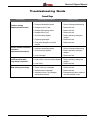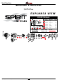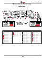
1
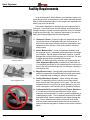
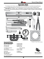
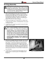
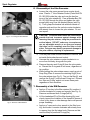
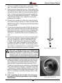
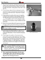
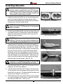
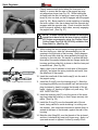
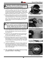
SERVICE AND REPAIR MANUAL
SPIRIT REGULATOR
PN RG100
Service & Repair Manual
Revised - 02/11
Spirit Regulator
Contents
Section 1 - Introduction
Warnings, Cautions, & Notes................................................................................................................. 3
Scheduled Service................................................................................................................................. 3
EAN/ Nitrox Service................................................................................................................................ 3
Facility Requirements............................................................................................................................. 4
Specialty Tools........................................................................................................................................ 5
Section 2 - Preliminary Inspection
External Inspection................................................................................................................................. 6
Immersion / Leak Test............................................................................................................................ 6
Intermediate Pressure Test..................................................................................................................... 7
Section 3 - Disassembly Procedures
General Guidelines................................................................................................................................. 8
First Stage Disassembly......................................................................................................................... 9
Second Stage Disassembly................................................................................................................. 12
Section 4 - Reassembly Procedures
General Guidelines............................................................................................................................... 15
First Stage Reassembly....................................................................................................................... 16
Second Stage Reassembly.................................................................................................................. 19
Secton 5 - Final Testing Procedures
First Stage Intermediate Pressure Test................................................................................................ 22
Second Stage Adjustment and Flow Test............................................................................................. 23
Subjective Breathing Test..................................................................................................................... 24
Flowbench Testing (optional)................................................................................................................ 25
External Leak Test................................................................................................................................ 25
Troubleshooting Guide
First Stage............................................................................................................................................ 26
Second Stage....................................................................................................................................... 27
Schematic & Parts Lists
Spirit First Stage................................................................................................................................... 28
Spirit Second Stage.............................................................................................................................. 29
Spirit Regulator Service and Repair Manual
2
Service & Repair Manual
SECTION
1
Introduction
This manual provides factory prescribed procedures for the correct service and repair of the
Spirit™ regulator, including the first and second stage. It is not intended to be used as an instructional manual for untrained personnel. The procedures outlined within this manual are to
be performed only by personnel who have received factory authorized training through a repair
seminar that has been directly sponsored by XS Scuba.
If you do not completely understand all of the procedures outlined in this manual, contact XS
Scuba to speak directly with a Technical Advisor before proceeding any further.
Warnings, Cautions, & Notes
Pay special attention to information provided in Warnings, Cautions, and Notes that are accompanied by one of these symbols:
A WARNING indicates a procedure or situation that may result in serious injury or death if instructions are not followed correctly.
A CAUTION indicates any situation or technique that will result in potential damage to the product, or render the product unsafe if instructions are not followed correctly.
A NOTE is used to emphasize important points, tips, and reminders.
Scheduled Service
Because the Spirit™ regulator is considered to be a life-supporting product, it is extremely
critical that it receives service according to the procedures outlined in this manual on a regularly
scheduled basis; at least once a year with normal or infrequent use.
NOTE: A unit that receives heavy or frequent use, such as in rental, instruction, or
commercial applications, should be serviced at least twice each year - or more often
- depending on the conditions of use and the manner in which it is maintained. (Refer
to the care and maintenance procedures outlined in the Spirit User's Guide.)
When performing service, whether it is a routine overhaul or a repair of a specific problem, it
is important to understand how the regulator is designed and how it operates. If you have any
questions, please consult your XS Scuba representative.
EAN/ Nitrox Service
Newly manufactured XS Scuba regulators are assembled and packaged to be compatible
with oxygen enriched air (EAN/ Nitrox), not to exceed 40% oxygen content. If the regulator is
going to be used for this application, however, it must be dedicated and clearly labled as such,
in order to prevent any crossover use with standard compressed air. Refer to the instructions
provided in the XS Scuba Authorized Service Document, titled - Regulator Parts Cleaning
Procedures.
CAUTION: It is important to avoid using, testing, or otherwise pressurizing a dedicated
EAN regulator with standard compressed air, which contains hydrocarbon contaminants.
3
Copyright ©2011 XS Scuba
Spirit Regulator
Facility Requirements
As an Authorized XS Scuba Dealer, your customers expect you
to provide top-notch overhaul service, both before and after the sale.
Next to airfills and gas blending, it is the single most important commodity your store can provide.
The service department is therefore the most important part of
your store. It should be clean and well lighted, and stocked with a
complete inventory of parts and all the specialty tools you will need
to get the job done right. As a minimum requirement, your service
facility should be equipped with the following items:
❏ Ultrasonic Cleaner – Select the right size model that can keep
up with the volume of equipment that your store services. A
built in timer and heater will help control the cleaning time and
temperature of the solution, since most solutions work best
when heated.
❏ Bench Mounted Vise – A vise is sometimes needed to hold
Ultrasonic Cleaner
the regulator secure – especially when removing the first stage
yoke retainer. Special care must be taken, however, to avoid
damage that can result from improper use of this tool. Be sure
to follow the instructions provided in this manual.
NOTE: XS Scuba especially endorses and recommends the
Jaws Gripmaster Bench Vise, available from Peter Built Co.
It is designed specifically for the professional dive store service
bench, and will prevent damage that can easily be caused by a
conventional vise.
❏ Magnification Lamp – Strong lighting and magnification are
essential requirements for performing a thorough parts inspection - especially when locating the source of a small leak.
❏ Quality Wrenches & Sockets – When working with brass
"Jaws" Gripmaster Vise
parts, it is especially critical to use the correct size wrench
and to ensure that it fits properly over the part. The use of an
adjustable wrench is very likely to cause damage to your customer's equipment, and should be strictly avoided at all times.
❏ Calibrated Inch-Pound and Foot-Pound Torque Wrenches –
It is important to follow the manufacturer's torque values
whenever they are specified, in order to avoid overtightening or
undertightening a part. This is especially important for smaller
parts and fittings, when overtightening can easily damage the
part. Torque wrenches that can be set for both inch-pound
and foot-pound measurements tend to be less accurate than
wrenches that are designed to measure torque within a specific
range.
Spirit Regulator Service and Repair Manual
4
Service & Repair Manual
Specialty Tools
For the finest tools, fixtures, and supplies that are designed and manufactured specifically for
servicing SCUBA equipment, we recommend one source for all your service facility’s needs.
Peter Built Co., in Galion, Ohio, is dedicated to serving the diving industry, and offers a wide selection of the most innovative specialty tools found anywhere to help you get the job done efficiently
- and done right.
1" - SIX POINT
Breaker Bar # 20-157-500
PETER BUILT
3/8"
Drive
(419) 468-2212
260 2.0 x 50
260 3.5 x 60
O-ring Tool Set #10-102-100
100
75
150
100
175
120
125
80
200
IP RANGE
125-150 PSI
60
140
225
IP RANGE
125-150 PSI
50
250
PSI
180
275
PSI
25
20
Piston Installation Bullet
M
160
40
Poppet Align/ Orifice Preset Tool, #20-785-400
Snap Ring Pliers # 10-101-500
Select Tool Kit (5 pcs) # 11-090-500
No. 4 Hook Spanner, #20-404-200
Custom (narrow diameter)
3/8" x 3" Drive Extension #20-156-500
I” Yoke Nut Socket #20-155-500
USE NO OIL
USE NO OIL
0
300
200
PETER BUILT
PETERinBUILT
CO.
"Quality
the making"
"Quality
in the making"
(419) 468-2212
(419) 468-2212
Dual Drive In-Line Adjusting Tool # 20-500-200
Intermediate Pressure
Test Gauge, #20-510-100
Second Stage Rim Clamp #20-790-200
Required Tools/ Lubricant
No. 4 Hook Spanner Wrench
PN #20-404-200
Dual Drive Adjusting Tool PN #20-500-200
Tech Driver IPG
PN #20-165-111
O-ring Tool SetPN#10-125-400
1/4" Slotted Screwdriver
PN #11-465-500
1/4" Nut Driver
PN #11-168-500
Small (.02) Blade Screwdriver
PN #11-133-500
Cristo LubePN #MS150
Hakko Side Cuts, 5"
PN #16-020-500
Snap Ring Pliers
11/16" Open End Wrench
3/4" Open End Wrench
5
Illustrations courtesy of Peter Wolfinger.
Galion, OH 44833
Phone: 419-468-2212
www.scubatools.com
Copyright ©2011 XS Scuba
SECTION
Spirit Regulator
2
Preliminary Inspection
External Inspection
1. Closely examine the conical filter to check for any signs
that contaminants have entered the system, including sea
water, rust, or aluminum oxide.
NOTE: A green discoloration of the filter indicates
that moisture has entered the regulator, and internal
corrosion has possibly occurred. Other types of discoloration may indicate that the regulator has been
used with a corroded cylinder. Advise the customer
of this, and the possible need to obtain service for
the cylinder.
2. Slide back the hose protectors, if present, to visually
inspect the condition of the hoses, especially at their fittings.
3. Closely examine the finish of the first stage to check for
any chips, scratches, or other damage that exposes the
brass beneath the finish.
CAUTION: Do not clean any parts that show damage
to their finish inside an ultrasonic cleaner.
4. Closely examine all parts of the first stage for any other
signs of external corrosion.
Immersion / Leak Test
1. Check to ensure that the regulator is fully assembled and
connected to a second stage, and that there are no open
ports or hoses. Connect the first stage to a cylinder that
is filled with 3,000 psi, and open the cylinder valve to
pressurize the regulator.
2. If leakage cannot be heard, or if the source of leakage
detected audibly is not obvious, immerse the first stage in
fresh water to check further for any signs of air leakage,
especially at the fittings of hoses.
3. Note the source of any leakage found and refer to
the Troubleshooting Guide to determine its possible
cause.
4. Close the cylinder valve and depress the second stage
purge button to depressurize the regulator before per-
Spirit Regulator Service and Repair Manual
6
Service & Repair Manual
forming the next procedure.
Intermediate Pressure Test
NOTE: It is not necessary to perform this test unless
a problem has been reported that requires diagnostic
troubleshooting and repair. When performing routine
overhaul service, proceed directly to the following
section, Disassembly.
1. Connect a calibrated intermediate pressure test gauge
to the regulator, either with a quick-disconnect inflator
hose or with the female fitting of a second stage LP hose,
depending on the connection of the test gauge.
CAUTION: To provide a safety relief valve in the
event that intermediate pressure exceeds 155-170
psi, ensure that a fully assembled and properly adjusted second stage is connected to the first stage
before pressurizing. Failure to relieve intermediate
pressure that exceeds 400 psi may result in damage
or rupture of the test gauge or LP hose, and could
cause serious personal injury.
2. Slowly open the supply valve to pressurize the first stage.
Closely monitor the IP test gauge to determine whether
the intermediate pressure rises above 145 psi.
3. Note the intermediate pressure indicated by the test
gauge, and purge the second stage several times to
determine whether lockup is achieved without creeping or
fluctuating back and forth.
4. If the intermediate pressure creeps up or otherwise fluctuates after cycling the regulator, wait for it to stabilize (if
possible) before making a final note of the intermediate
pressure.
NOTE: Correct intermediate pressure for the first
stage is 140 (±5) psi, with an inlet pressure between
2,500 - 3,000 psi.
5. Close the supply valve and depress the second stage
purge button to depressurize the system before attempting to perform any disassembly.
▼ After completing the Preliminary Inspection, proceed
to Section 3 – Disassembly
7
Copyright ©2011 XS Scuba
SECTION
Spirit Regulator
3
Disassembly Procedures
General Guidelines
▼ Prior to performing any disassembly, check to ensure that
the service facility is well equipped with all the tools and
parts needed to perform a complete service from start to
finish. DO NOT attempt to perform the service unless all
of the required tools and parts are available.
▼ All o-rings are classified as being either dynamic or
static. Dynamic o-rings are those which sustain friction
and movement, as they are either mounted directly onto
a moving part, or create a seal against a moving part.
Static o-rings simply create a seal between two nonmoving parts, and are therefore less subject to wear than
dynamic o-rings. After passing close inspection, static
O-rings may sometimes be reused, although this is not
necessarily recommended. Dynamic O-rings must be
automatically discarded and replaced with every service,
regardless of age or appearance.
▼ Refer to the schematic and parts list while performing
these procedures. Each part is identified by its reference
number shown on the drawing the first time it is referred
to in the procedure.
▼ Do not attempt to reuse parts that are designated to
be automatically discarded and replaced with the parts
provided in the overhaul parts kit. These parts should be
shown to the customer, however, to ensure their confidence and satisfaction that complete overhaul service has
been performed.
▼ Inspect all reusable parts as directed, either during or immediately following the disassembly procedures. When
in doubt, compare the part with one that is new to best
determine its condition.
Spirit Regulator Service and Repair Manual
8
Service & Repair Manual
First Stage Disassembly
CAUTION: Whenever possible, use only plastic or brass
O-ring tools for removing O-rings in order to prevent
damage to the sealing surface. Steel instruments, such
as dental picks, can easily damage the sealing surface
of a softer brass part, causing irreparable leakage and
requiring the part to be replaced with new.
1. Before disassembling the first stage, remove the low
pressure second stage hose with a b" open end wrench,
the high pressure hose with a s" open end wrench, and
the low pressure inflator hose with a 2" (or other size
required) open end wrench. Remove all remaining port
plugs(13&15) with a ®" (4mm) hex key.
2. Remove and inspect the O-rings(12&14) on these items
to determine their condition, and discard them if any signs
of decay are found.
3. Loosen the yoke screw(2) as needed to remove the dust
cap(4) from the yoke(3).
NOTE: It will be necessary to use a bench mounted
vise to hold the first stage secure throughout the
next procedure. This ensures the best protection
against slippage and accidental damage to soft
metal parts. If an ordinary bench vise will be used,
the first stage must be mounted outside the vise
with the use of a vise mounting tool fastened into
the high pressure port. To ensure the best available
protection against damage, XS Scuba specifically
recommends the Gripmaster Vise, available from
Peter Built Co.
4. Secure the first stage inside the Gripmaster Vise, so that
the piston cap(23) faces straight up and the yoke screw
faces down. Fit the #4 Hook Spanner (Peter Built PN
20-404-200) onto the piston cap to mate the pin inside
one of the bore holes (see Fig. 1). While holding the tool
securely engaged, turn the piston cap counter-clockwise
to loosen no more than 4 turn (90 degrees) so that it can
later be removed by hand. Do not loosen it further than 4
turn at this time.
5. Loosen the vise, and resecure the first stage in the opposite position, so that the yoke or DIN adapter faces
straight up.
9
Fig. 1 – Loosening the Piston Cap
Copyright ©2011 XS Scuba
Spirit Regulator
6. Disassembly of the Yoke Connector
a. Loosen the yoke screw several turns counter-clockwise. Place a 1" Yoke Retainer Socket (Peter Built PN
20-156-500) inside the yoke and over the hex features of the yoke retainer(8). Pass a Breaker Bar (PN
20-157-500) through the yoke, and tighten the yoke
screw lightly snug over the dimpled feature (see Fig.
2). Then, grasp the breaker bar with both hands on
opposite ends and turn the socket counter-clockwise
with steady force to loosen the yoke retainer. Do not
use impact.
Fig. 2 – Loosening the Yoke Retainer
Fig. 3 – Removal of Filter Retaining Ring
CAUTION: The socket and breaker bar combination
provide the best insurance against damage while
removing the yoke retainer, using the procedure described above. DO NOT, under any circumstances,
use an adjustable wrench or an open end wrench
that does not fit completely over the flats on both
sides. Doing so may result in permanent damage to
the yoke retainer, requiring its replacement.
b. Turn the yoke screw counter-clockwise to remove, and
set aside the breaker bar and socket.
c. Unscrew the yoke retainer counter-clockwise to remove from the body, along with the yoke.
d. Remove the main seal O-ring(9) from the yoke retainer. Discard the O-ring and do not reuse, regardless of
its condition.
e. While holding the yoke retainer secure, apply a pair of
Snap Ring Pliers to remove the retaining ring(5) from
the yoke retainer (see Fig. 3). Tap out the filter(6), and
remove the O-ring(7) with a brass O-ring tool. Discard
the filter and O-ring, and do not reuse these parts
regardless of their condition.
7. Disassembly of the DIN Connector
Fig. 4 – Removal of DIN Retainer
Spirit Regulator Service and Repair Manual
a. Apply a 4" hex key to the filter retainer(3b), andturn it
counter-clockwise to loosen and remove (see Fig. 4).
Remove and discard both O-rings(3a&3c).
b. Lift the handwheel(3f) off the filter housing(3g), and
closely inspect the condition of the threads to ensure it
is free of any burrs or other damage that could prevent
proper threading.
c. Apply a m" open-end or box wrench to the filter housing, and loosen it counter-clockwise with steady force
to remove from the first stage body. Remove and discard the filter(3d) and both O-rings(3e).
10
Service & Repair Manual
8. Remove the saddle(10) and check for any signs of damage. Set it aside to be reused if none are found.
9. Remove the first stage from the vise. While holding the
first stage body secure with one hand, unscrew the piston
cap (pre-loosened in Step 4) counter-clockwise with the
other. Lift the piston cap with the piston(21) straight up
and off the first stage body and spring(17). Remove the
collar(22) and discard or set it aside to be reused, depending on its condition.
10. Pull the piston straight out of the piston cap, being careful to avoid rocking or twisting it in order to prevent metal
against metal contact. Remove and discard both dynamic O-rings(19&20).
11. To remove the high pressure seat(18) from the end of the
piston shaft, carefully insert a slim rod through the head
and shaft of the piston. Firmly press the rod against the
underside of the seat to press it out of the piston shaft
(see Fig. 5). Discard the seat, and do not attempt to reuse.
12. Remove the high pressure valve spring and spring isolators(16) from the body. Inspect the spring isolators for
any signs of damage or distortion, and discard if any
is found. Closely inspect the spring with a magnifier
to check for any signs of damage or corrosion that has
permeated the wall of the metal. Set the spring aside to
be reused if it is determined to be in satisfactory condition
with no signs of permanent corrosion or damage.
Fig. 5 – Removal of HP Seat
CAUTION: If damage is found, or if the intermediate
pressure was measured lower than 135PSI during
preliminary inspection, replace the spring. DO NOT
attempt to raise the intermediate pressure by adding
spring isolators to compensate for a damaged spring.
13. Under strong lighting, closely inspect the inner bore and
all sealing surfaces of the first stage body with a magnifier, including the intermediate and high pressure ports,
and especially, the machined orifice cone (see Fig. 6).
Check to ensure there are no scratches or other damage
that could contribute to leakage. If damage is found that
is determined to cause irreparable leakage, it will be necessary to discard the first stage body and replace it with
new. Do not attempt to polish the sealing surface of the
orifice cone.
▼ After completing the disassembly of the first stage,
proceed to the following procedure - Second Stage
Disassembly.
11
Fig. 6 – HP Cone Inspection
Copyright ©2011 XS Scuba
Spirit Regulator
Second Stage Disassembly
CAUTION: Whenever possible, use only plastic or
brass O-ring tools for removing O-rings in order to
prevent damage to the sealing surface. Steel instruments, such as dental picks, can easily damage the
sealing surface of a softer brass part, causing irreparable leakage and requiring the part to be replaced
with new.
1. Slide back the hose cover to expose the connection of the
LP hose.
2. While holding the inlet fitting(20) secure with an n" openend wrench, apply a 17mm open-end wrench to the fitting
of the LP hose. Turn the hose fitting counter-clockwise to
loosen and remove.
3. Using a plastic or brass O-ring tool, carefully remove the
O-ring(25) from the post inside the hose fitting.
CAUTION: When performing the above step, be
very careful to avoid scratching the O-ring sealing
surface. Doing so may cause a permanent leak that
will require the replacement of the LP hose.
4. Using an n" open end wrench, turn the inlet fitting counter-clockwise to loosen from the second stage housing(12), and unscrew it completely by hand to remove.
5. Snip the plastic tie-strap(21) that holds the mouthpiece(23), and gently pull the mouthpiece off the second
stage housing. Inspect the mouthpiece to ensure that it is
supple and free of any tears or corrosion. If any damage
is found that could result in discomfort or leakage, discard
the mouthpiece and do not reuse.
6. While holding the second stage secure with one hand,
firmly grasp the retaining ring(17) with the other, and turn
the ring counter-clockwise to loosen and remove it, along
with the diaphragm cover(16).
NOTE: If the retaining ring is difficult to loosen, XS
Scuba recommends using the Rim Clamp (P/N 20790-200), available from Peter Built Co. Complete
instructions are provided with the tool.
7. Separate the diaphragm cover from the retaining ring,
and closely inspect the cover to ensure that it is perfectly
round and free of damage. If any damage is found, discard the cover and replace with new.
8. Lift out the diaphragm(14) and thrust washer(15) from the
Spirit Regulator Service and Repair Manual
12
Service & Repair Manual
second stage housing. Inspect the diaphragm to ensure
that it is supple and free of any pinholes, tears, corrosion,
or other damage. If any damage is found, discard it and
replace with new.
9. Using a small flat blade screwdriver, rotate the metal retaining clip(13) over the groove of the housing plug(1) inside
the second stage housing until the notch in the center faces
up. Place the tip of a 2mm flat blade screwdriver inside this
notch, and gently lift the clip off the groove. (See Fig. 7.)
Fig. 7 – Removal of Retaining Clip
10. Apply a c" hex key to turn the housing plug counter-clockwise
until loosened, and remove it from the housing. Carefully
remove the O-ring(2) with a plastic tool, and discard. Closely
xamine the condition of the housing plug, especially around
the threads and O-ring seating groove. Discard if any damage is found that may cause leakage, or set it aside to be
reused.
11. While holding the lever(18) lightly depressed, press the inlet
end to slide the entire valve assembly out of the other end of
the second stage housing (see Fig. 8). Remove and discard
the inlet fitting O-ring(19).
Fig. 8 – Removal of Valve Assembly
12. Turn the air barrel over to allow the balance shuttle cap(3)
and LP spring(4) to drop out (see Fig. 9). Inspect the spring
closely with a magnifier to check for any signs of corrosion.
Discard it if corrosion is found, and do not reuse.
13. Gently remove the lever from the air barrel by lifting out one
leg first, and then the other. Be careful to avoid bending or
stretching either leg.
Fig. 9 – Removal of LP Spring
14. Turn the air barrel over to allow the poppet(6) to drop out.
Using fingernails or a plastic tool, carefully remove the LP
seat(7) and small O-ring(5). Discard both soft parts, and
do not reuse. Closely inspect the poppet around all seating
surfaces, and compare it with new to ensure no damage is
visible. If damage is found, discard the poppet and replace
with new.
15. Remove the white lever pad(9) from the air barrel. Discard,
and do not reuse.
16. While holding the air barrel secure, apply a medium blade
screwdriver to the slotted head of the adjustable orifice(10),
and turn it counter-clockwise to disengage its threads.
NOTE: The orifice is O-ring sealed, and it will remain
inside the air barrel after it has been unthreaded. The
following step must be performed to remove the orifice
without damaging its polished sealing surface.
13
Copyright ©2011 XS Scuba
Spirit Regulator
17. When the orifice has been unthreaded from the air barrel,
carefully insert a small wooden or plastic dowel through
the opposite end of the valve body, directly over the sealing edge of the orifice. Gently press out the orifice. (See
Fig. 10.)
18. To avoid using a sharp tool that can damage the orifice,
squeeze the O-ring(11) between thumb and forefinger to
remove it from the orifice head. Discard the O-ring and
do not reuse.
19. Closely examine the orifice with the use of a magnifier,
checking for any scratches or other damage to the sealing edge and the groove that holds the O-ring (see Fig.
11). If any damage or wear is found, discard the orifice
and do not attempt to reuse. If it is in reusable condition,
set it aside on a soft surface to keep it isolated from other
metal parts.
Fig. 10 – Removal of Adjustable Orifice
20. Remove the exhaust deflector(24) from the second stage
housing to expose the exhaust valve(22) for inspection.
NOTE: To facillitate the removal of the exhaust deflector, first place it in hot (120°-150°F) water for 2-3
minutes and allow it to soften.
21. Closely inspect the exhaust deflector to check for any
signs of damage that may have been caused by abuse
or improper disassembly. If found, discard it and replace
with new,
22. Closely inspect the condition of the exhaust valve to
ensure that it is evenly seated against the second stage
housing on all sides, and free of any tears, holes, or other
signs of decay. Peel back the lip on all sides to ensure it
is supple and returns to its original position. If any wear
or damage is detected, or if the material feels stiff or decayed, pull the exhaust valve straight out of the housing
and discard it.
NOTE: It is not necessary to remove the exhaust
valve diaphragm unless it shows signs of wear or
decay upon inspection. Once the diaphragm is
removed, however, it will be permanently stretched
and then must be replaced with new.
▼ After completing the disassembly of the first and
second stages, refer to the instructions provided in
the XS Scuba Authorized Service Document, titled Regulator Parts Cleaning Procedures.
Spirit Regulator Service and Repair Manual
14
Fig. 11 – Orifice Inspection
Service & Repair Manual
4
section
Reassembly Procedures
General Guidelines
▼ Refer to the schematic parts list, that highlights automatic
replacement parts which should be discarded and replaced
with new during reassembly. These parts are provided in the
Annual Service Kit.
▼ Before performing any reassembly, it is important to individually inspect all parts, both new and those that are being reused,
to ensure that each part and component is perfectly clean and
free of any dust, decay, or blemishes.
▼ If the regulator has been serviced for use with EAN/Nitrox, it is
important to don powderless latex gloves before handling any
parts, including O-rings, in order to avoid contaminating the
parts with skin oil.
▼ Prior to dressing, inspect all O-rings with magnification to ensure they are supple, clean, and completely free of any scoring
or decay that would impair proper sealing.
▼ XS Scuba recommends Christo-Lube® MCG-11 (PN MS150)
to be used exclusively for the lubrication and dressing of Orings and other internal parts. Christo-Lube® provides superior
lubrication to that of silicone grease, especially in high pressure
(DIN) systems greater than 3,000 psi, and extreme temperature conditions. It is also non-reactive to oxygen, and is approved for use with EAN/Nitrox.
CAUTION: Silicone grease is not compatible with oxygen
enriched air, and must be strictly avoided when servicing a regulator that will be used with EAN/ Nitrox. The
entire regulator will otherwise become contaminated,
and rendered unsafe for use with any mixture of oxygen
enriched air.
▼ Dress all O-rings with a visible film of Christo-Lube, but avoid
applying excessive amounts, as this may attract particulate
matter that can cause accelerated wear or damage to the
O-ring.
CAUTION: The use of aerosol spray or petroleum based
lubricants must be strictly avoided. The propellant gas
or petroleum base may attack or weaken plastic or rubber parts.
▼ Use all replacement parts provided in the XS Scuba Authorized
Dealer parts kit.
15
Copyright ©2011 XS Scuba
Spirit Regulator
First Stage Reassembly
WARNING: DO NOT attempt to use any other manufacturer's part as a substitute for any XS Scuba part,
regardless of any similarity in shape, size, or appearance. Doing so may render the product unsafe, and
could result in serious injury or death.
1. Generously lubricate and install the piston head Oring(20) onto the head of the piston(21), and install the
piston shaft O-ring(19) onto the piston shaft.
2. Install the high pressure seat(18) into the end of the piston shaft, and check to ensure it is seated flush with no
visible protrusion (see Fig. 12).
3. Set the piston cap(23) on a flat surface with the open end
facing up. Place the head of the piston inside the cap so
that it rests perfectly level above the threads, and then
gently press the piston straight down into place until it is
fully seated.
Fig. 12 – HP Seat Installation
CAUTION: Be careful to prevent the piston from
becoming cocked at an angle as the head travels
past the threads of the piston cap. The O-ring could
otherwise become unseated or damaged, and metal
on metal contact could cause damage to the piston
or the piston cap.
4. Fit the collar(22) over the open end of the piston cap, so
that it seats flush aginst the shoulder.
5. Over the support post inside the intermediate pressure
chamber of the first stage body, install the same color
(thickness) and number of spring isolators(16) that were
disassembled from the high pressure chamber.
CAUTION: Unless the spring has been replaced
with new, it is very important to reinstall the same
number and color combination of spring isolators
as the original quantity that was removed during the
disassembly procedure. No more than two spring
isolators may be used between the spring and the
body, and no more than one spring isolator may be
used between the spring and the piston.
6. Apply a light film of lubricant to both ends of the high
pressure spring(17), and place the spring down over the
support post inside the high pressure cavity of the body.
Fig. 16 – Swivel Retainer w/ O-rings
Spirit Regulator Service and Repair Manual
16
Service & Repair Manual
7. Place the remaining spring isolator directly over the top of
the spring.
8. Hold the body secure with the open intermediate pressure
end facing straight up, and position the piston cap over
the body so that the piston shaft is aligned through the
center of the spring. Mate the piston cap onto the body
and firmly press downward while turning it clockwise to
engage the threads (see Fig. 13). Continue turning by
hand until snug.
9. Fit the saddle(10) onto the high pressure (inlet) end of the
first stage.
10. Secure the first stage inside the Gripmaster Vise with the
high pressure end facing straight up.
Fig. 13 – Installing Piston Cap
Fig. 14 – Torquing Yoke Retainer
11. Reassembly of the Yoke Connector
a. Install the O-ring(7) into the yoke retainer(8), followed
by the conical filter(6). Closely examine the retaining ring(5) to identify which side is flat and which side
is slightly rounded. Using snap ring pliers, install the
retaining ring into the groove above the filter, with the
flat side facing out.
b. Lubricate and install the main seal O-ring(9) into the
groove in the bottom of the yoke retainer.
c. Being careful to ensure that the O-rings remain properly seated, insert the threaded end of the yoke retainer through the bottom of the yoke(3), and mate the
yoke retainer into the inlet port of the first stage body.
Turn the retainer clockwise by hand until snug.
d. Apply a torque wrench with the 1" Yoke Nut Socket
(PN 20-155-500) and 3"x a" Socket Drive Extension
(PN 20-156-500). Tighten the yoke retainer to a measurement of 24 foot-lbs (±1). (See Fig. 14.)
e. Install the dust cap(4) onto the yoke, and mate the
yoke screw(2) into the yoke. Turn the screw one to
two revolutions clockwise to engage the threads.
12. Reassembly of the DIN Connector
a. Install both O-rings(3e) and filter(3d) into the filter
housing(3g).
b. Mate the filter housing into the inlet port of the first
stage body, and turn clockwise by hand until snug.
Apply a torque wrench with a m" deep socket to tighten the filter housing to a torque measurement of 17
foot-lbs (±1). (See Fig. 15.)
17
Copyright ©2011 XS Scuba
Spirit Regulator
c. Fit the handwheel(3f) over the filter housing with the
male threaded side facing up.
d. Install both O-rings(3c&3a) onto the filter retainer(3b).
Mate the filter retainer into the filter housing, and turn
clockwise by hand until snug. Apply a torque wrench
with 4" hex key socket to tighten the filter retainer to a
torque measurement of 130 inch-lbs (±10).
13. Resecure the first stage inside the Gripmaster Vise, so
that the piston cap faces straight up.
14. Fit the #4 Hook Spanner (Peter Built PN 20-404-200)
over the piston cap(23) to engage the pin with one of the
bore holes, and hold the tool securely engaged. While
holding the tool securely engaged, turn the piston cap
clockwise only until it has reached the extent of its thread
engagement, and do not tighten beyond snug.
15. Loosen the vise to remove the first stage, and remove the
vise mounting tool.
16. Lubricate and install the O-rings(12&14) onto all
hoses and port plugs. Install the LP hoses and port
plugs(13&15) into their respective ports in the first stage.
Apply a calibrated torque wrench with ®" (4mm) hex key
socket (or appropriate size crow foot for hoses) to tighten
the port plugs and hoses to a torque measurement of 38
inch-lbs (±2).
▼ After completing the reassembly of the first stage, proceed to the following procedure - Second Stage Reassembly.
Spirit Regulator Service and Repair Manual
18
Fig. 15 – Torquing DIN Housing
Service & Repair Manual
Second Stage Reassembly
WARNING: DO NOT attempt to use any other manufacturer's part as a substitute for any XS Scuba part,
regardless of any similarity in shape, size, or appearance. Doing so may render the product unsafe, and
could result in serious injury or death.
1. Install the exhaust valve(22) into the second stage housing(12) by gently pulling the stem through the hole in
the center of the sealing area, until the barb has passed
through and is securely seated inside.
Fig. 21 – Lever pad Features
NOTE: Prior to installing the exhaust deflector(24),
place it in hot (120°-150°F) water for 2-3 minutes and
allow it to soften.
2. Fit the exhaust deflector(24) over the top ridge of the second stage housing, so that the two corners are securely
seated, and then stretch the lower portion down until it
snaps securely into place.
Fig. 22 – Air Barrel Orientation
CAUTION: Do not use a tool to install the exhaust
deflector. Doing so may cause serious damage to the
seating flange, requiring replacement of the housing.
3. Closely examine both sides of the white lever pad(9) to
identify that the mounting tabs on both legs are rounded
on one side and flat on the other. (See Fig. 21.) Hold
the air barrel with the flat cut facing down, and place the
clip over the tube with the rounded side facing toward
the flange, so that one tab engages in the hole next to it.
Then, gently press the opposite leg into place so the the
other tab engages in the opposite hole. When done correctly, the lever pad should rest flush against the flange,
with both tabs securely seated. (See Fig. 22.)
CAUTION: Do not stretch the legs of the lever pad,
or attempt to install it if damage has occurred.
Fig. 23 – Poppet Features
Fig. 24 – Correct Poppet Orientation
4. Insert the stem of the LP seat(7) into the large end of the
poppet(6). DO NOT use adhesive.
5. Lubricate and install the small O-ring(5) over the groove
on the opposite end of the poppet, being careful to avoid
stretching it excessively. Closely examine the shape and
features of the poppet. (See Fig. 23.)
6. While holding the air barrel with the flat cut facing straight
up, guide the poppet into the tube, LP seat first, with the
ears facing straight down. (See Fig. 24.)
19
Fig. 25 – Poppet Correctly Installed
Copyright ©2011 XS Scuba
Spirit Regulator
7. Closely examine both holes where the lever pad is installed, to ensure that the ears of the poppet are properly aligned as shown (see Fig. 25). While holding the
air barrel with the flat cut facing up, insert one leg of the
lever(18) into one hole, so that it engages with the poppet
(see Fig. 26). Being careful to avoid stretching or bending
the lever, rotate it over the air barrel until the opposite leg
engages with the opposite side. Check to ensure that the
lever is properly seated on both sides, securely engaging
the poppet ears. (See Fig. 27.)
Fig. 26 – Lever Installation
Fig. 27 – Correct Lever Orientation
NOTE: To better control the orientation of the poppet
inside the air barrel while the lever is being installed,
XS Scuba recommends using the Poppet Align/
Orifice Preset Tool (P/N 20-785-400), available from
Peter Built Co. (See Fig. 28.)
8. While holding the second stage housing right side up with
the front facing you, slide the valve assembly into the
opening in the right side of the housing. Gently depress
the lever, and then slide the valve assembly through the
opening on the inlet side. Be careful to ensure that both
lever arms fit squarely between the two flanges inside the
housing, and then slide fully in place so that the lever pad
is seated flush. (See Fig. 29.)
9. Apply a light coat of lubricant to both ends of the poppet
spring(4), and place the spring inside the air barrel, over
the small end of the poppet.
10. Insert the small end of the shuttle cap(3) into the end of
the poppet spring.
Fig. 28 – Poppet Alignment/ Preset Tool
11. Install the O-ring(2) onto the housing plug(1). Mate the
housing plug directly over the shuttle cap, and screw the
plug clockwise by hand to engage the threads of the air
barrel. Apply a c" hex key to tighten only until snug. DO
NOT OVERTIGHTEN.
12. Install the retaining clip(13) over the groove of the housing plug inside the housing, so that it snaps securely into
place. (See Fig. 30.)
13. Install the O-ring(19) over the threaded inlet of the air
barrel, being careful to avoid stretching it or rolling over
the threads. Use a smooth instrument to ensure that it is
seated at the base of the threads, against the wall of the
housing.
Fig. 29 – Valve Assembly Completely Installed
Spirit Regulator Service and Repair Manual
14. Mate the inlet fitting(20) over the threads of the air barrel,
and turn it clockwise by hand until finger snug. Apply a n"
open end wrench to tighten it further by exactly 8 turn.
20
Service & Repair Manual
CAUTION: Be careful to avoid overtightening the
inlet fitting, which can crack the wall of the second
stage housing, requiring its replacement.
15. Install the O-ring(11) onto the head of the adjustable orifice(10) and carefully insert the orifice into the inlet of the
air barrel with the polished cone facing in. Using a small
wooden or plastic down, press the orifice in so that it rests
against the threads inside the air barrel. (See Fig. 31.)
16. Apply a medium blade screwdriver to the slotted head of
the orifice inside the air barrel, and turn it clockwise while
closely watching the lever. When the lever starts to drop,
stop – do not turn the orifice any further. This will indicate
that the orifice has made contact against the LP seat.
(See Fig. 32.)
NOTE: To pre-set the orifice at exactly the correct
depth inside the air barrel, XS Scuba recommends
using the Poppet Align/ Orifice Preset Tool (P/N 20785-400), available from Peter Built Co. Complete
instructions are provided with the tool. (See Fig. 33.)
Fig. 30 – Installing Retaining Clip
Fig. 31 – Installing Orifice
17. Lay the diaphragm(14) inside the housing, directly over
the lever with its raised surface facing up, and then the
thrust washer(15).
18. Fit the front cover(16) inside the housing so that it seats
directly over the diaphragm. Turn it as needed to align
the logo horizontally level (See Fig. 34.)
19. Mate the retaining ring(17) over the front cover and into
the housing, and turn it clockwise to engage the threads.
While holding the front cover secure with one hand, tighten the retaining ring until snug with the other. Be careful
to avoid over-tightening.
20. Install the mouthpiece(23) onto the housing, correctly oriented with the top facing up. Fasten a tie-strap(21) over
the mouthpiece with the locking tab facing toward the
inlet coupling, and cinch it snug. Trim the excess material
close to the locking tab.
Fig. 32 – Preliminary Adjustment of Orifice
Preset Depth
.480” - .490”
Fig. 33 – Using the Orifice Pre-Set Tool
▼ After completing the reassembly of the second stage,
proceed to Section 5 – Final Testing.
Fig. 34 – Proper Logo Alignment
21
Copyright ©2011 XS Scuba
SECTION
Spirit Regulator
5
Final Testing Procedures
CAUTION: If the regulator will be used with EAN/
Nitrox, it is important to pressurize and flow test
the regulator using only hydrocarbon-free gas. The
regulator will otherwise become contaminated with
hydrocarbons if normal compressed air is used.
Industrial grade compressed Nitrogen is strongly
recommended as a lower cost alternative to EAN/
Nitrox for the purposes of flow testing.
First Stage Intermediate Pressure Test
1. Connect a calibrated intermediate pressure test gauge to
the regulator, either with a quick-disconnect inflator hose
or with the female fitting of a second stage LP hose, depending on the connection of the test gauge.
CAUTION: To provide a safety relief valve in the
event that intermediate pressure exceeds 155-170
psi, ensure that a fully assembled and properly adjusted second stage is connected to the first stage
before pressurizing. Failure to relieve intermediate
pressure that exceeds 400 psi may result in damage
or rupture of the test gauge or LP hose, and could
cause serious personal injury.
2. Initially connect the first stage to a supply of 300 psi filtered test gas, and slowly open the supply valve to pressurize the first stage. Closely monitor the IP test gauge to
determine whether the intermediate pressure rises above
145 psi.
CAUTION: If the intermediate pressure continues
to rise above 200 psi, immediately shut the test gas
supply valve. Refer directly to the Troubleshooting
guide, and remedy as needed before proceeding
any further.
3. When the intermediate pressure has been determined to
be 145 psi or less, close the supply valve and purge the
second stage to depressurize the system. Connect the
Spirit Regulator Service and Repair Manual
22
Service & Repair Manual
first stage to a supply of 2,500 - 3,000 psi test gas.
NOTE: Correct intermediate pressure for the first
stage is between 135-145 psi, with a supply pressure
of 2,500 - 3000 psi.
4. Open the supply valve again while monitoring the IP test
gauge to ensure that the intermediate pressure does not
rise above 145 psi. If the intermediate pressure rises
above 145 psi, immediately close the supply valve and
purge the system. Refer to the Troubleshooting Guide.,
and remedy as needed before proceeding.
5. Repeatedly purge the second-stage approximately 15-20
times to cycle the regulator. Then, check the test gauge
to determine whether the intermediate pressure locks up
consistently after each cycle and remains stable at 140
(±5) psi, with no signs of creeping or fluctuation. If the intermediate pressure is not within the specified range, or if
it fails to lock up with no creep, refer to the Troubleshooting Guide to determine the cause of the problem. Repeat
this procedure after it is corrected.
Second Stage Adjustment and Flow Test
1. Connect the IP Test Gauge onto the inlet fitting of the
Inline Adjusting Tool, and mate the opposite fitting of the
tool onto the inlet fitting of the second stage. Pull back
the knurled knob to retract the slotted drive, and tighten
the tool clockwise onto the inlet fitting only until finger
snug. (See Fig. 35.)
2. Mate the female fitting of the LP hose onto the male fitting
of the IP Test Gauge, and tighten the swivel nut clockwise
until finger snug.
3. Install the LP hose into an intermediate pressure port of
the first stage regulator after it has been verified to be
properly serviced, with a stable intermediate pressure of
140 (±5) psi . Apply a torque wrench with 17mm crowfoot to tighten to 38 (±2) inch-lbs.
Fig. 35 – Inline Adjustment Tool w/ IP Gauge
4. Ensure that all the first stage ports are sealed, and connect the first stage with a filtered gas supply of 2,5003,000 psi. Slowly open the valve to pressurize the regulator. Listen to verify that a leak can be heard from the
second stage valve, and proceed to step 6.
a. If airflow cannot be heard, it will be necessary to
initiate a slight leak between the orifice and poppet.
Press the knurled knob inward to engage the slotted
drive of the Inline Adjustment Tool with the head of
23
Copyright ©2011 XS Scuba
Spirit Regulator
the orifice inside the inlet fitting. Then, turn the orifice
slightly counter-clockwise while lightly depressing
the purge cover to prevent wear on the seat. Do not
adjust any further than is needed to establish a slight
leak.
5. Hold the drive of the Inline Adjustment Tool engaged with
the orifice. While lightly depressing the purge cover, turn
the orifice slightly clockwise a very small fraction of a turn.
Pause after each adjustment to listen, and be careful to
avoid over-adjusting beyond the point that the leak has
stopped. When the leak has stopped, purge the second
stage again to ensure that it does not return. Observe
the IP Test Gauge while purging to verify that it indicates
a stable intermediate pressure after each cycle, with no
creep or fluctuation.
CAUTION: Over-adjustment of the orifice can cause
excessive spring load in the second stage valve, and
may impair the regulator’s performance.
6. When the second stage is properly adjusted with no leaks
or lever slack, depressurize and purge the system to disconnect the LP hose.
7. Reconnect the LP hose to the inlet coupling, and apply a
torque wrench with 17mm crow-foot to tighten the fitting
to a torque measurement of 55 inch-lbs (±5).
Subjective Breathing Test
1. While the regulator is connected to a cylinder containing
2,500 – 3,000 psi and pressurized, turn the second stage
adjustment knob completely out counterclockwise, and
verify that a slight leak of airflow is present.
2. Slowly turn the adjustment knob clockwise to verify that
the airflow stops between 2 -1 turn.
3. Turn the adjustment knob completely in clockwise to
maximum opening effort, and depress the purge to ensure that an adequate volume of air flows through the
mouthpiece, sufficient to clear the second stage.
4. Turn the adjustment knob out counter-clockwise until a
leak can be heard, and then back just until the leak stops.
Breathe from the second stage.
▼ A properly serviced and adjusted regulator should deliver
air upon deep inhalation without excessive inhalation effort, freeflow, or vibration. When exhaling, there should
be no resistance or sticking of the exhalation valve. If
any of these problems occur, refer to the Troubleshooting
Spirit Regulator Service and Repair Manual
24
Service & Repair Manual
Guide on pages 26-27.
Flowbench Testing (optional)
The Subjective Breathing Test, combined with the Intermediate Pressure Test, will sufficiently verify the regulator's
performance in most circumstances. As an additional test, a
Magnahelic flowbench can be used to verify the second stage
opening effort, which should not exceed 1.5 column inches
H2O.
External Leak Test
After first stage reassembly and final adjustment of the
second stage has been completed, submerge the entire
regulator in a test tank of clean water while pressurized
with 2,500-3000 psi. Observe any bubbles arising from the
submerged regulator over a one minute period. The recommended time is necessary due to slower bubble formation
that occurs in smaller leaks. Disassemble the regulator at
the source of the leak to check sealing surfaces, assembly
sequence and component positioning in order to correct the
problem(s).
NOTE: The location of extremely small leaks can
best be detected by applying a soap solution to
the leak area. Before disassembling to correct any
leaks, rinse the entire regulator thoroughly with fresh
water and blow out all residual moisture with filtered,
low-pressure (25 psi) test gas. Refer to the Troubleshooting Guide.
▼ When the second stage has been adjusted and tested
according to the prescribed procedures, close the cylinder
valve completely, and purge the second stage to depressurize the system. Loosen the yoke screw to remove the
first stage from the cylinder, and seal the dust cap over
the inlet fitting. Disinfect the mouthpiece, and dry the
regulator completely with a clean towel. This completes
the overhaul service procedures for the Spirit regulator.
25
Copyright ©2011 XS Scuba
Spirit Regulator
Troubleshooting Guide
First Stage
SymptomPossible CauseTreatment
Excessive inhalation resistance 1. Cylinder valve partially opened.
1. Fully open valve, turn back 1/4 turn. from both second stages
Check fill pressure.
2. Cylinder valve requires service.
2. Connect to a different cylinder.
3. Filter is clogged.
3. Replace filter with new.
4. Low intermediate pressure.
1. Piston cap is loose.
Low
intermediate pressure
1. Tighten piston cap.
2. Replace spring and spring washers.
2. Main valve spring is damaged.
4. See below.
3. Incorrect number of spring washers
3. (With new spring only:) Install up to a total of three washers.
High
intermediate pressure
1. HP seat damaged or worn.
1. Replace HP seat.
2. Piston O-rings damaged or worn.
2. Replace O-rings.
3. Piston is damaged.
3. Replace orifice.
4. First stage body damaged internally.
4. Replace body.
Leakage
from beneath yoke
5. Incorrect number of spring washers
5. Remove washers.
1. Yoke retainer O-ring damaged or worn.
1. Replace O-ring.
CAUTION: All repairs must be performed with a complete overhaul service, unless
the problem is detected immediately after a complete overhaul service has already
been performed. Do not attempt to perform partial service if the regulator shows
any signs of use. For additional troubleshooting assistance, contact your XS Scuba
distributor.
Spirit Regulator Service and Repair Manual
26
Service & Repair Manual
Troubleshooting Guide
Second Stage
SymptomPossible CauseTreatment
Freeflow or leakage
(Adjustment knob turned in)
1. Excessive intermediate pressure.
1. Refer to first stage troubleshooting
2. Damaged or worn LP seat.
2. Replace with new.
3. Damaged orifice sealing surface.
3. Replace with new.
4. Damaged orifice O-ring.
4. Replace with new.
5. Orifice incorrectly adjusted.
5. Reset to preliminary setting and readjust.
6. Poppet spring damaged.
7. Lever pad is damaged or incorrectly
installed.
6. Replace with new.
7. Replace with new.
Excessive Inhalation Resistance
1. Insufficent intermediate pressure.
1. Refer to first stage troubleshooting
or Hesitation
2. Orifice incorrectly adjusted.
2. Reset to preliminary setting and (Adjustment
knob turned out)
readjust.
3. Lever is damaged.
3. Replace with new.
Insufficient airflow when
1. Lever is slack, or orifice incorrectly adjusted. 1. Reset to preliminary settings and readjust.
purge button is depressed
2. Lever is bent.
2. Replace with new.
Water entering second stage
1. Exhaust valve worn or damaged.
1. Replace with new.
2. Mouthpiece worn or damaged.
2. Replace with new.
3. Adjustment knob or O-ring damaged,
3. Disassemble and inspect, replace or reassemble as required. incorrectly installed, or worn.
27
Copyright ©2011 XS Scuba
Spirit Regulator
Schematic & Parts List
Spirit First Stage
E X P LO D E D VI EW
300 BAR DIN Adapter
29
30
28
24
25
31
26
27
DIN Adapter
Service Kit
1
2
5
4
Spirit Regulator Service and Repair Manual
3
6
7
8
9
10
14
12
15
13
28
11
16
#
Part #
1
24
25
26
27
28
29
30
31
RP100
RP200-37
RP100-25
RP200-17
RP200-38
RP200-29
RP100-29
RP100-30
RP200-29
Description
16
25.00
0.50
6.00
0.50
1.50
0.50
15.00
10.00
0.50
Includes:
Part # RK7
Dealer 3.50
17
Dealer
Complete DIN Adapter
O-ring
Filter Retainer
O-ring
Filter
O-ring
Handwheel
DIN Retainer
O-ring
24 26 27 28 31
21
18 19
20
22
23
Service & Repair Manual
Schematic & Parts List
Spirit First Stage
56
52
54
57
59
58
65
66
53
67
51
55
68
64
43
42
44
45
46
48
47
49
60
50
62
41
40
First Stage
Service Kit
63
Second Stage
Service Kit
61
Includes:
Includes:
Part # RK3
Dealer 6.00
5
9
6
Part # RK2
Dealer 7.00
7
18 19 20
#
Part #
Description
# Part #
1
RP200-01
Yoke Screw Decal
1.00
17
RP100-17
2
RP200-02
Yoke Screw
8.00
18
RP100-18
3
RP200-03
Dust Cap w/ String & O-ring 3.00
19
4
RP100-04
Yoke
20.00
20
5
RP200-05
Retaining Clip
1.00
6
RP200-06
Filter
7
RP200-07
8
RP100-08
9
Description
Part #
#
HP Spring
6.00
40
RP250-28
Plug
4.00
55
RP250-16
Front Cover
HP Seat
2.00
41
RP250-02
O-ring
0.50
56
RP250-17
Retaining Ring
RP100-19
O-ring
0.50
42
RP250-03
Balance Shuttle Cap
2.00
57
RP250-18
Lever
4.00
RP100-20
O-ring
0.50
43
RP250-04
LP Spring
2.00
58
RP200-12
O-ring
0.50
21
RP100-21
Piston
20.00
44
RP250-05
O-ring
0.50
59
RP250-20
Inlet Fitting
2.00
1.50
22
RP100-22
Collar
2.00
45
RP250-06
Poppet
5.00
60
RP250-11
“No Bump” Tie Strap 0.50
O-ring
0.50
23
RP100-23
Piston Cap
15.00
46
RP250-07
LP Seat
2.00
61
RP250-22
Exhaust Valve
2.50
Yoke Retainer
8.00
47
RP250-08
Air Barrel - Brass
16.00
62
RP250-23
Mouthpiece
3.50
RP200-29
O-ring
0.50
47
RP250-08S
Air Barrel - Titanium
35.00
63
RP250-24
Exhaust Tee
6.00
10
RP100-10
Saddle 3.00
48
RP250-09
Lever Pad
2.00
64
RP200-19
O-ring
11
RP100-11
Main Body
35.00
49
RP250-10
Adjustable Orifice
4.00
65
LP30
LP Hose - 30”
12
RP200-31
O-ring
0.50
50
RP200-19
O-ring
0.50
66
RP200-29
O-ring
13
RP200-32
LP Port Plug
2.00
51
RP250-12
Housing Body 10.00
67
RP250-25
Hose Protector6
2.00
14
RP200-17
O-ring
0.50
52
RP250-13
Retaining Clip
3.00
68
RP250-26
Hose Cover
15
RP200-16
HP Port Plug
2.00
53
RP250-14
Diaphragm
5.00
16
RP100-16
Spring Washer
0.50
54
RP250-15
Thrust Washer
1.00
29
Description
Dealer
# Part #
50 58 60 64 66
Dealer
11
Dealer
41 44 46 48
Description
Dealer
5.00
15.00
0.50
12.00
0.50
2.00
Copyright ©2011 XS Scuba