1
BLACK MAX™ Power Supply
Model 4002E
Operating and Service Manual
Printed in U.S.A.
ORTEC® Part No. 740270
Manual Revision J
1202
Advanced Measurement Technology, Inc.
a/k/a/ ORTEC®, a subsidiary of AMETEK®, Inc.
WARRANTY
ORTEC* warrants that the items will be delivered free from defects in material or workmanship. ORTEC makes
no other warranties, express or implied, and specifically NO WARRANTY OF MERCHANTABILITY OR
FITNESS FOR A PARTICULAR PURPOSE.
ORTEC’s exclusive liability is limited to repairing or replacing at ORTEC’s option, items found by ORTEC to
be defective in workmanship or materials within one year from the date of delivery. ORTEC’s liability on any
claim of any kind, including negligence, loss, or damages arising out of, connected with, or from the performance
or breach thereof, or from the manufacture, sale, delivery, resale, repair, or use of any item or services covered
by this agreement or purchase order, shall in no case exceed the price allocable to the item or service furnished
or any part thereof that gives rise to the claim. In the event ORTEC fails to manufacture or deliver items called
for in this agreement or purchase order, ORTEC’s exclusive liability and buyer’s exclusive remedy shall be release
of the buyer from the obligation to pay the purchase price. In no event shall ORTEC be liable for special or
consequential damages.
Quality Control
Before being approved for shipment, each ORTEC instrument must pass a stringent set of quality control tests
designed to expose any flaws in materials or workmanship. Permanent records of these tests are maintained for
use in warranty repair and as a source of statistical information for design improvements.
Repair Service
If it becomes necessary to return this instrument for repair, it is essential that Customer Services be contacted in
advance of its return so that a Return Authorization Number can be assigned to the unit. Also, ORTEC must be
informed, either in writing, by telephone [(865) 482-4411] or by facsimile transmission [(865) 483-2133], of the
nature of the fault of the instrument being returned and of the model, serial, and revision ("Rev" on rear panel)
numbers. Failure to do so may cause unnecessary delays in getting the unit repaired. The ORTEC standard
procedure requires that instruments returned for repair pass the same quality control tests that are used for
new-production instruments. Instruments that are returned should be packed so that they will withstand normal
transit handling and must be shipped PREPAID via Air Parcel Post or United Parcel Service to the designated
ORTEC repair center. The address label and the package should include the Return Authorization Number
assigned. Instruments being returned that are damaged in transit due to inadequate packing will be repaired at the
sender's expense, and it will be the sender's responsibility to make claim with the shipper. Instruments not in
warranty should follow the same procedure and ORTEC will provide a quotation.
Damage in Transit
Shipments should be examined immediately upon receipt for evidence of external or concealed damage. The carrier
making delivery should be notified immediately of any such damage, since the carrier is normally liable for damage
in shipment. Packing materials, waybills, and other such documentation should be preserved in order to establish
claims. After such notification to the carrier, please notify ORTEC of the circumstances so that assistance can be
provided in making damage claims and in providing replacement equipment, if necessary.
Copyright © 2002, Advanced Measurement Technology, Inc. All rights reserved.
*ORTEC® is a registered trademark of Advanced Measurement Technology, Inc. All other trademarks used
herein are the property of their respective owners.
iii
CONTENTS
WARRANTY . . . . . . . . . . . . . . . . . . . . . . . . . . . . . . . . . . . . . . . . . . . . . . . . . . . . . . . . . . . . . . . . . . . . . . . ii
SAFETY INSTRUCTIONS AND SYMBOLS . . . . . . . . . . . . . . . . . . . . . . . . . . . . . . . . . . . . . . . . . . . . . . . iv
SAFETY WARNINGS AND CLEANING INSTRUCTIONS . . . . . . . . . . . . . . . . . . . . . . . . . . . . . . . . . . . . . v
1. DESCRIPTION . . . . . . . . . . . . . . . . . . . . . . . . . . . . . . . . . . . . . . . . . . . . . . . . . . . . . . . . . . . . . . . . . . . 1
2. SPECIFICATIONS . . . . . . . . . . . . . . . . . . . . . . . . . . . . . . . . . . . . . . . . . . . . . . . . . . . . . . . . . . . . . . . . 1
3. INSTALLATION . . . . . . . . . . . . . . . . . . . . . . . . . . . . . . . . . . . . . . . . . . . . . . . . . . . . . . . . . . . . . . . . . .
3.1. UNPACKING . . . . . . . . . . . . . . . . . . . . . . . . . . . . . . . . . . . . . . . . . . . . . . . . . . . . . . . . . . . . . .
3.2. SELECTING THE MAINS VOLTAGE . . . . . . . . . . . . . . . . . . . . . . . . . . . . . . . . . . . . . . . . . . . .
3.3. CONNECTION OF THE 4002E TO A NIM BIN . . . . . . . . . . . . . . . . . . . . . . . . . . . . . . . . . . . . .
3.3.1. Requirements for Attached Bin . . . . . . . . . . . . . . . . . . . . . . . . . . . . . . . . . . . . . . . . . . .
3.3.2. Instructions for Attaching Bin . . . . . . . . . . . . . . . . . . . . . . . . . . . . . . . . . . . . . . . . . . . . .
2
2
2
3
3
3
4. OPERATING INSTRUCTIONS . . . . . . . . . . . . . . . . . . . . . . . . . . . . . . . . . . . . . . . . . . . . . . . . . . . . . . 5
5. MAINTENANCE . . . . . . . . . . . . . . . . . . . . . . . . . . . . . . . . . . . . . . . . . . . . . . . . . . . . . . . . . . . . . . . . . 5
5.1. FACTORY REPAIR . . . . . . . . . . . . . . . . . . . . . . . . . . . . . . . . . . . . . . . . . . . . . . . . . . . . . . . . . 5
iv
SAFETY INSTRUCTIONS AND SYMBOLS
This manual contains up to three levels of safety instructions that must be observed in order to avoid
personal injury and/or damage to equipment or other property. These are:
DANGER
Indicates a hazard that could result in death or serious bodily harm if the safety instruction
is not observed.
WARNING
Indicates a hazard that could result in bodily harm if the safety instruction is not observed.
CAUTION
Indicates a hazard that could result in property damage if the safety instruction is not
observed.
Please read all safety instructions carefully and make sure you understand them fully before attempting to
use this product.
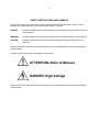
In addition, the following symbol may appear on the product:
ATTENTION–Refer to Manual
DANGER–High Voltage
Please read all safety instructions carefully and make sure you understand them fully before attempting to
use this product.
v
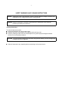
SAFETY WARNINGS AND CLEANING INSTRUCTIONS
DANGER
Opening the cover of this instrument is likely to expose dangerous voltages. Disconnect the
instrument from all voltage sources while it is being opened.
WARNING Using this instrument in a manner not specified by the manufacturer may impair the
protection provided by the instrument.
Cleaning Instructions
To clean the instrument exterior:
! Unplug the instrument from the ac power supply.
! Remove loose dust on the outside of the instrument with a lint-free cloth.
! Remove remaining dirt with a lint-free cloth dampened in a general-purpose detergent and water
solution. Do not use abrasive cleaners.
CAUTION To prevent moisture inside of the instrument during external cleaning, use only enough liquid
to dampen the cloth or applicator.
!
Allow the instrument to dry completely before reconnecting it to the power source.
vi
1
ORTEC MODEL 4002E
BLACK MAX™ POWER SUPPLY
1. DESCRIPTION
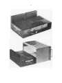
The ORTEC Model 4002E BLACK MAX™ Power
Supply is designed to supply dc power to a NIM Bin
when the application demands exceptionally high
power. The BLACK MAX Power Supply can be
purchased separately for use with existing NIM
Bins, or it can be ordered attached to a 4001C NIM
Bin. Mounting hardware is supplied to make the
Model 4002E compatible with all ORTEC NIM Bins.
With minor mounting modifications the 4002E can
be used with most standard NIM Bins. The ORTEC
4001C NIM Bin is recommended for use with the
4002E because the 4001C distributes the power
with copper bus bars to minimize the voltage drop
at each module's power plug. The BLACK MAX
Power Supply is designed to exceed recommended
power supply specifications for Type V-H supplies
as defined in DOE/ER-0457T.
Regulated dc power supplied to the attached bin by
the BLACK MAX is conservatively rated at +6 V @
12 A, !6V@12A, +12V@4A, !12V@4A, +24V@
2 A, and !24 V @2A, provided the total output dc
power does not exceed 300 W at ambient
temperatures up to 50°C. In addition, 115 V ac is
available up to 0.5 A.
Protection against overload is provided in several
ways. When the heat sink temperature exceeds
95°C, the red warning indicator is illuminated on the
attached bin control panel. When the heat sink
temperature exceeds 110°C, the power supply is
automatically shut down, causing both the power
and temperature indicator lights to turn off.
Recovery from thermal overload is automatic when
the thermal load is reduced. Output currents from
the dc supplies are internally limited to 120% of
their rated values by foldback circuits. This provides
overload and short-circuit protection. On the +6 V
and !6 V dc supplies, crowbar circuits limit the
output voltage to 7.5 V to protect integrated circuits.
Fuses protect the ac inputs to the power supply.
An external slide switch allows selection of either
115 or 220 V ac as the power input. By changing
pins on an internal connector, this selection can be
altered to 100 and 200 V ac. An international
standard IEC power connector permits power cords
and plugs that meet local electrical standards to be
used for the input power. Control of the primary
power is provided by the On/Off switch on the NIM
Bin control panel.
Connection of power and control lines to the NIM
Bin is provided by the standard interface connector
specified in DOE ER-0457T. Mechanical mounting
of the power supply to the bin is with brackets
utilizing the standard bolt pattern specified in
DOE/ER-0457T.
2. SPECIFICATIONS
INPUT 103–129 or 200–258 V ac, 47–63 Hz. An
external slide switch selects nominal input voltages
of 115 or 220 V ac. Changing pins on an internal
connector allows operation at 88-110 V or
191–239 V ac, 47–63 Hz, with the external slide
switch selecting nominal voltages of 100 or
200 V ac. Input current at 115 V ac is nominally 7 A
for a 300-W dc output simultaneous with a 0.5-A,
115-V ac output. Dual fuse input uses 8-A SB
U.S.A. standard fuses for 100 or 115 V ac, 60 Hz
and 5-A SB metric fuses for 200 and 220 V ac,
50 Hz operation.
DC OUTPUTS Maximum rated output currents are:
DC
Voltage
+6 V
!12 V
+24 V
Maximum
Current
12 A
4A
2A
DC
Voltage
!6 V
!12 V
!24 V
Maximum
Current
12 A
4A
2A
Maximum dc output power from 0 to 50°C is
300 W. Derate 3%/°C for 50 to 60°C.
2
115 V ac OUTPUT Unregulated voltage. Maximum
current limited only by the input fuses when
operated in the 100- or 115-V ac settings. Limited to
0.5 A on the 200- and 220-V ac settings when the
dc load is 300 W. Output voltage is nominally 115 V
ac in the 115-V and 220-V input modes. Output
voltage is nominally 100 V ac in the 100-V and
200-V input modes.
REGULATION <± 0.1%(typically±0.05%)for ±12 V
and ±24 V, and <±0.2% (typically ±0.1%) for ±6 V
over the combined range of zero to full load with
the specified input voltage range for measurements
made within a 1-minute period. Regulation <±0.3%
for ±12 V and ±24 V, and <±0.6% for ±6 V over any
24-hour period at constant ambient temperature for
the same load and input ranges after a 60-minute
warmup.
LONG TERM STABILITY DC output voltages
change <±0.5% (after a 60-minute warmup) over a
6-month period at constant load, line voltage, and
ambient temperature.
S
at any frequency
OUTPUT IMPEDANCE <0.3
up to 100 kHz for the dc outputs.
TEMPERATURE COEFFICIENT <0.02%/°C, 0 to
60°C.
NOISE AND RIPPLE <3 mV peak-to-peak for any
output as observed on a 50-MHZ bandwidth
oscilloscope.
:
RECOVERY TIME <100 s to return to within
±0.1% of the rated voltage for all dc outputs for any
input voltage change within the rated range or for a
change of load current from 10% to 100% of full
load.
CIRCUIT PROTECTION Both input power lines
include fuses. The power supply is automatically
turned off by an internal switch if the temperature of
the heat sink exceeds 110°C. Recovery is
automatic when the temperature decreases to a
safe value. Provision is made for activating a
temperature warning light on the NIM Bin control
panel to advise that the temperature limit is being
approached. This warning occurs at and above a
heat sink temperature of 95°C. All dc outputs
include a current foldback circuit to limit the output
current to nominally 120% of the rated value. This
feature provides short-circuit and overload
protection. Recovery is automatic after removal of
the overload condition. Over-voltage protection for
the ±6-V outputs prevents these outputs from
exceeding ±7.5 V, respectively, to protect the
integrated circuits that are commonly powered by
these supply voltages.
WEIGHT 13.6 kg (30 lb) net weight, 18.1 kg (40 lb)
shipping weight.
DIMENSIONS 43.2 cm (17.0 in.) wide, 26.9 cm
(10.6 in.) deep, and 8.9 cm (3.5 in.) high, except for
rear-mounted, 15.2-cm- (6.0-in.-) high heat sink.
VOLTAGE ADJUSTMENT ±2% minimum range.
Resettability <±0.05% of the supply voltage.
3. INSTALLATION
3.1. UNPACKING
Unpack the unit, being careful to retain all packing
materials until the unit has been checked for
possible concealed damage. The power cord is
packed with the unit and attaches to a three-pin
connector that is mounted on the rear of the 4002E
BLACK MAX Power Supply.
3.2. SELECTING THE MAINS VOLTAGE
The 4002E BLACK MAX Power Supply is designed
so that the transformer primary can be connected in
a configuration that is compatible with the available
mains voltage. Check the voltage level to be used
and select the appropriate range on the 4002E
BLACK MAX Power Supply. The normal selection
is either 115 V ac or 220 V ac, and the selection is
made using the slide switch on the side of the
power supply near the power cord. Alternatively, the
4002E BLACK MAX Power Supply can be wired so
that the selection can be either 100 V ac or
200 V ac. Modification of the 4002E BLACK MAX
Power Supply for 100/200 V ac operation requires
exchanging two wires on the primary of the
transformer. There are two sections of the
transformer; one section has two wires (black,
3
white) and the other section has three wires (black,
white, and black/white). Changes are made to the
transformer section that has the three wires.
The following steps are required to modify the
4002E Power Supply for 100/200 V ac operation:
DANGER
Opening the cover of this
instrument is likely to expose
dangerous voltages. Disconnect
the instrument from all voltage
sources before opening it.
1. Install crimp pin (Part No. 490590) to the
black/white wire on the section of the transformer
having three wires. (This is the only unused wire on
the primary section of the transformers.)
2. Using the proper tool (Part No. 635690), extract
the black wire from position 3 of the primary
connector wiring housing. NOTE: This black wire
must be connected to the same primary section as
the black/white wire.
3. Install the black/white wire into position 3 of the
primary connector wiring housing.
4. Cover exposed pin of the black wire removed
from the primary connector wiring housing with
shrink tubing for safety.
5. Install the 100/200 V ac operation label to the
chassis near the ac voltage select switch.
6. Install an 8-A (SB) (250V), size 3AG fuse for
100-V or 120-V operation. Install a 5-A (T) (250V),
size 5×20-mm fuse in the fuse holder supplied with
the power supply for 200-V or 220-V operation.
3.3. CONNECTION OF THE 4002E TO A
NIM BIN
The 4002E BLACK MAX Power Supply is normally
attached to an ORTEC 4001C Modular System Bin.
However, the 4002E is designed to DOE/ER-0457T
specifications and may be attached, in the space
provided, to any bin manufactured to those
specifications.
3.3.1. Requirements for Attached Bin
The 4002E BLACK MAX Power Supply is designed
to provide very high currents to NIM modules that
contain heavy loads. The NIM Bin used with this
power supply must be capable of handling the large
currents demanded by those loads. The power
On/Off switch mounted on the bin and its
associated primary circuit wiring must be rated to
handle 8 A. ORTEC bins that can handle the 8-A
primary current have a label inside the bin near the
On/Off switch that states “8 A Power Switch.” An
8-A Switch Conversion Kit can be ordered from
ORTEC as Part No. 735110.
The bin wiring distributing the dc voltages must also
have an impedance low enough to yield negligible
voltage drops at the rated currents for the supply.
Although the ORTEC Model 4001A NIM Bin will
function acceptably with the 4002E power supply,
the Model 4001C Bin is strongly recommended as
the more desirable choice. The ORTEC Model
4001C Bin employs copper bus bars for power
distribution. This typically results in more than a
factor of 10 lower voltage drop at maximum current.
3.3.2. Instructions for Attaching Bin
For attachment to a bin other than an ORTEC bin,
please refer to the appropriate instruction manual.
The On/Off switch and other controls necessary to
operate the Power Supply are part of the bin and
not furnished with the Power Supply.
For attachment to the ORTEC bin, the following
steps are advised:
WARNING Always disconnect the power cord at
the power supply chassis before
connecting or disconnecting the binpower supply connector (PG13PG14). Failure to do so will result in
a shock hazard at PG14 and can
also damage the power supply or the
contents of the bin.
1. The adapter blocks used to mount the Power
Supply to the bin are shipped attached to the Power
Supply. These adapter blocks are polarized and
mount in one orientation for ORTEC 4001A and
4001C Bins, and in another orientation for older
ORTEC and other manufacturers' bins. One
adapter block is marked on top with an "L", and the
other adapter block is marked on top with an "R".
2. First remove the adapter blocks from the Power
Supply. They will be mounted to the bin and then
the Power Supply will be mounted to the adapter
blocks.
4
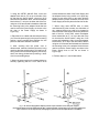
3. Using the ORTEC 4001A/C Bins, mount the
adapter block with an "R" on top to the side of the
bin that has the On/Off switch, using two 10-32
screws and lockwashers. Next, mount the adapter
block with an "L" on top to the other side of the bin,
using two 10-32 screws and lockwashers. Note that
the mounting holes in the adapter blocks that are
used to mount the Power Supply are closer to the
bin than to the Power Supply as shown in
Figure 1(A).
4. Place the bin on a table with the back part facing
you. Place the power supply in the proper mounting
position, leaving enough space between the two
pieces to attach the interface connector.
5. After ensuring that the power cord is
disconnected, mate the interface connector, being
careful to align the polarizing pins. Fold and form all
wiring close to the connector edges to prevent any
wires from being pinched and producing a short
circuit in succeeding steps.
screws between the sides of the Power Supply and
the adapter blocks, being careful not to pinch any
wires or to use undue force on any parts. With the
adapter blocks in proper orientation, the side of the
Power Supply will closely butt to the back of the bin.
7. When using older ORTEC bins, or those
manufactured by other vendors, the orientation of
the adapter blocks may need to be changed to
ensure that the Power Supply will closely butt to the
back of the bin. In this case, mount the adapter
block marked with an "L" on top to the side of the
bin that has the On/Off switch, using two 10-32
screws and lockwashers. Next, mount the adapter
block with an "R" on top to the other side of the bin
using two 10-32 screws and lockwashers. Note that
the mounting holes in the adapter blocks that are
used to mount the Power Supply are closer to the
Power Supply than to the bin as shown in
Figure 1(B).
8. Perform steps 4, 5, and 6 listed above.
6. Mount the power supply to the adapter blocks by
securely tightening the four 1/4-in. black 10-32
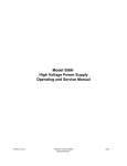
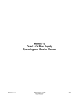
Fig. 1. Bin to Power Supply Block Adapter provides simple installation of bins and power supplies.
(A) Illustrates Adapter used with ORTEC 4001A/C Bins. (B) Shows Adapter repositioned for use with earlier ORTEC bins.
These conversions are accomplished by exchanging the positions of the two Adapter Blocks on the NIM bin.
5
4. OPERATING INSTRUCTIONS
The available current from the power supply is
specified in Section 2, "DC OUTPUTS." Care must
be used to ensure natural convection of heat
dissipation by the heat sinks and power transformer.
When used at maximum power loading on a bench
or tabletop, the bin and power supply should be in
an open space, placed upon blocks at least 1 in. off
the table mounting surface to allow maximum
ventilation. When used in a rack, attention should
be paid to placement of other heat-generating
equipment Adequate unobstructed space on all
sides is necessary for convection ventilation and
cooling. If the bin contains other heat-generating
equipment, a blower may be advisable to remove
the dissipated heat.
When it is necessary to rack mount several bins
and power supplies, especially when other
heat-generating equipment is located within the
rack, the term "ambient temperature" becomes less
clearly defined. A better guide to maximum power
loading capability is to monitor the heat sink
temperature. Never allow the heat sink temperature
to run continuously above 95 C. Although this is not
the maximum operating temperature, any additional
temperature rise due to other conditions of the
system may force the supply out of tolerance and
may cause it to automatically shut down operation.
Should your operation produce a heat sink
temperature of 85 C, a blower to remove the heat
is recommended.
5. MAINTENANCE
The 4002E BLACK MAX Power Supply needs no
routine maintenance or adjustment. If a problem
develops and troubleshooting becomes necessary,
the top and bottom screen covers should be
removed to provide access to the components.
WARNING While probing inside the 4002E
BLACK MAX Power Supply
chassis, use extreme caution.
There are two shock-hazard
locations to regard: the wiring
side of the input line cord
connector block and the four
thermal switches (S1, S2, S3,
and S4) mounted against the
heat sink. These two locations
contain exposed primary circuit
conductors.
Most of the components mounted on the heat sink
can be replaced fairly easily. If replacement is
required, remove power cord and then remove the
four mounting screws that hold the inner chassis.
Proceed by removing all wire connections
associated with the inner chassis components.
Once the inner chassis is removed and out of the
way, access to the heat sink components is
available. It may also be necessary to remove the
two large 10,000- F capacitors, C8 and C13,
located in the center of the board in order to gain
easy access to the diode bridges, D2 and D14, on
the heat sink. When replacing a component, be
sure to use the same hardware, which includes the
thermal pad insulators on the heat sink side of the
component, on the replaced components. All
replaced heat sink components need to be
tightened with a torque wrench to 5 in./lb.
:
5.1. FACTORY REPAIR
This instrument can be returned to the ORTEC
factory for service and repair at a nominal cost. Our
standard repair procedures ensure the same quality
control and checkout that are used for a new
instrument. Always contact the ORTEC Customer
Service Department at (865) 482-4411, before
returning an instrument for repair, to obtain shipping
instructions and the required Return Authorization
Number. Write this number on both the address
label and package to ensure proper handling when
the instrument reaches the factory.
6
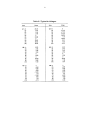
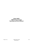
Table 5.1 Typical dc Voltages.
7
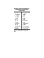
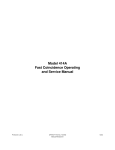
Bin/Module Connector Pin Assignments For
Standard Nuclear Instrument Modules
per DOE/ER-0457T.
Pin
1
2
3
4
5
6
7
8
9
*10
*11
12
13
14
15
*16
*17
18
19
20
21
22
Function
+3 V
-3V
Spare bus
Reserved bus
Coaxial
Coaxial
Coaxial
200 V dc
Spare
+6 V
-6V
Reserved bus
Spare
Spare
Reserved
+12 V
- 12 V
Spare bus
Reserved bus
Spare
Spare
Reserved
Pin
23
24
25
26
27
*28
*29
30
31
32
*33
*34
35
36
37
38
39
40
*41
*42
G
Function
Reserved
Reserved
Reserved
Spare
Spare
+24 V
- 24 V
Spare bus
Spare
Spare
117 V ac (hot)
Power return ground
Reset (Scaler)
Gate
Reset (Auxiliary)
Coaxial
Coaxial
Coaxial
117 V ac (neutral)
High-quality ground
Ground guide pin
Pins marked (*) are installed and wired in
ORTEC’s 4001A and 4001C Modular System
Bins.
8