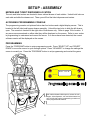
1
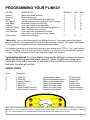
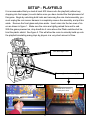
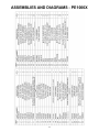
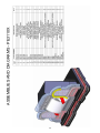
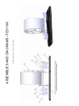
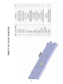
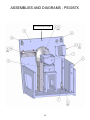
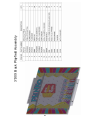
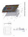
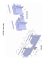
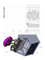
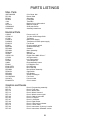
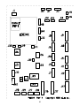
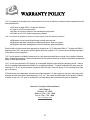
1
2
TABLE OF CONTENTS
Safety and Warnings
3
Setup
Game Play
Feature
Meters
Programming
Errors
Playfield
4
5
5&6
6
7
Trouble Shooting
Security Slam Switches
Power supply
8
9
Assembly Diagrams
Cabinet PE1000X
Big Bonus Wheel PE3110X
Skill Coin Chute PE1006X
Ticket Drawer PE3011X
Programming Console PE3011X
Coin Drawer PE1009X
Playfield Deck PE3130
Deck PE3076
Cabinet Layout PE1100X
Marquee PE3127X
10 - 11
12 - 14
15 - 16
17 - 18
19
20
21-23
24 - 25
26
27
Spares
29
Wiring Diagrams
See Insert
Main Logic Board Connector Layout
30
Warranty
31
REVISION F : PLINKO - ICE
2-11-2010
3
SAFETY AND WARNINGS
BEFORE YOU BEGIN
WARNING: WHEN INSTALLING THIS GAME, A GROUNDED A.C. RECEPTACLE MUST BE USED. FAILURE
TO DO SO COULD RESULT IN INJURY TO YOURSELF OR OTHERS. FAILURE TO USE A GROUNDED RECEPTACLE COULD ALSO CAUSE IMPROPER GAME OPERATION, OR DAMAGE TO THE ELECTRONICS.
DO NOT DEFEAT OR REMOVE THE GROUNDING PRONG ON THE POWER CORD FOR THE SAME REASON AS GIVEN ABOVE. USING AN IMPROPERLY GROUNDED GAME COULD VOID YOUR WARRANTY.
HAVE A QUALIFIED ELECTRICIAN CHECK YOUR A.C. RECEPTACLE TO BE SURE THE GROUND IS FUNCTIONING PROPERLY. DO NOT WASH YOUR GAME WITH A PRESSURE WASHER.
AVERTISSEMENT: lors de l'installation de ce jeu, la terre AC récipient doit être utilisé. Ne pas le faire pourrait entraîner un préjudice à vous ou à d'autres. Le non-recours à la terre récipient pourrait également causer une mauvaise opération de jeu, ou les dommages causés à l'électronique. NE PAS détériorer ou de retirer la broche de
terre sur le cordon d'alimentation pour la même raison, comme indiqué ci-dessus. Indûment l'aide d'un jeu de la
terre pourrait annuler votre garantie. Ont un électricien qualifié de vérifier votre récipient AC pour s'assurer que le
sol fonctionne correctement. Ne lavez pas votre jeu avec une laveuse à pression.
INSTALLATION
The game comes ready to play with just a few simple things to keep in mind.
1. Plug the game into the A.C. outlet and turn on power to the game. The switch for the game is located on a
power module on the outside rear of the game.
THIS GAME IS DESIGNED TO DISSIPATE STATIC ELECTRICITY THROUGH THE GROUNDING PLANE OF THE
GAME. IF THE A.C. GROUND DOES NOT WORK, THE GAME COULD DISCHARGE STATIC ELECTRICITY
THROUGH THE GAME CIRCUITRY, WHICH COULD CAUSE DAMAGE.
2. Make sure the game is level after installation. It is necessary to make sure the game is level for safety
concerns.
3. Check that the A.C. voltage rating on the back of the game matches the A.C. voltage of your location.
THE POWER SUPPLY IS NOT VOLTAGE ADJUSTABLE. TO OPERATE THE GAME AT VOLTAGES OTHER THAN
THOSE IT WAS DESIGNED FOR. PLEASE CONTACT OUR SERVICE DEPARTMENT FOR VOLTAGE CONVERSION
INFORMATION.
WARNING
DO NOT remove any of the components on the main board (e.g. compact flash and eproms) while
the game is powered on. This may cause permanent damage to the parts and the main board. Removing any main board component part while powered on will void the warranty.
Ne retirez pas l'un des composants sur la carte principale (par exemple Compact Flash et
EPROMs), tandis que le jeu est sous tension. Cette mai causer des dommages permanents aux
parties et la carte principale. Suppression de tout bord principal élément sous tension alors que annulera la garantie.
NOTE: THIS GAME IS INTENDED FOR INDOOR USE ONLY.
ON THE BACK PANEL OF THE GAME: WARNING: SHOCK HAZARD - DO NOT OPEN. REFER
SERVICING TO SERVICE PERSONNEL.
REMARQUE: CE JEU EST DESTINÉ POUR USAGE À L'INTÉRIEUR SEULEMENT.
SUR LE PANNEAU ARRIÈRE DU JEU: AVERTISSEMENT: RISQUE DE CHOC - NE PAS OUVRIR. RÉPARATION À UN PERSONNEL DE SERVICE.
4
SETUP - INTRODUCTION
Game play:
The player starts the game by moving the coin chute to skillfully drop their coin to light up the word
“PLINKO”. As the coin falls it is deflected off the pegs just like on the TV show. If the player is able
to light the word “PLINKO”, they are able to spin the big bonus wheel! Players receive tickets for
coins that fall over the edge and in some cases, just for playing!
• Bonus wheel emulates “The Price is Right Big Wheel Spin”.
• Playfield replicates the real “PLINKO!” board as seen on TV.
• Spell PLINKO! by lighting each letter for a chance to win the Big Bonus.
• Move coin chute back and fourth for skillful aiming.
• Win tickets for coins over the edge.
• Win tickets just for playing (Operator configurable).
Features:
• Ability to set pre-lit letters.
• Ability to turn on chasing lights.
• Ability to set mercy tickets and coin over edge.
• Adjustable bonus feature (how much to apply toward the bonus).
• Easy slide pull out ticket door to access.
• Ticket dispensers.
• Coin and ticket meters.
• Operator adjustments.
• Error codes.
• High reliable playfield motor with 1 year warranty.
• Easy to program.
• Self error/fault checking.
• Slam security switch on each station.
• Tilt protection.
• Made in the USA.
.
5
SETUP - ASSEMBLY
METERS AND TICKET DISPENSER LOCATION
The coin and ticket meters are located in lower cabinet drawer of each station. Unlock both locks on
each side and slide the drawers out. There you will find the ticket dispenser and meters.
ACCESSING PROGRAMMING CONSOLE
The programming console unit pictured below has four buttons and a digital display screen. This is
located in the left ticket and hopper drawer assembly. Unlock the two locks to slide the left drawer
open. The console is located on the right side of that drawer only. Refer to page 19 for location. If
any errors are encountered on either side they will be displayed on the screen. Refer to error codes
in programming to understand and correct the errors. If no errors have been detected, the current
software version will be displayed on the screen.
PROGRAMMING
Press the “PROGRAM” button to enter programming mode. Press “SELECT UP” and “SELECT
DOWN” to move the cursor to cycle through options. Press “ADVANCE” to change the settings the
cursor is currently on. Press the “PROGRAM” button to exit programming and re-start the game.
PROGRAM
SELECT UP
Plinko V1.00 1K
ADVANCE
SELECT
DOWN
Both cabinet drawers slide open to access the coin
hopper, ticket dispenser, coin and ticket meters but
only the left side has the programming console unit
which programs both stations.
6
PROGRAMMING YOUR PLINKO!
OPTION
Volume1
Volume2
Cylon
JFP (Mercy)
Over Edge
Feature
Power On Lights
Attract Time
Coin Dispense
Factory reset
DESCRIPTION
Game and attract Volumes
Music Volume only
If set to 1 red LED must be lit to light letter
Tickets given when coin goes in or just for playing
How many Tickets over the Edge
How many tickets to the wheel kitty
How many letters are lit when you turn power on
When it will say come on down.
How many coins to dispense per swipe
(This option only in the card swipe version)
Reset factory settings
DEFAULT
5
5
0
1
5
4
0
3
1
MIN
0
0
0
0
0
2
0
0
MAX
7
7
1
2
18
18
3
30
0
0
1
“Wheel kitty” refers to the bonus wheel’s two different bonuses. The mega bonus is the highest
amount of tickets on the wheel and the bonus is all the remaining numbers. This option is divided by
2, one goes to the mega bonus and the other to remaining numbers.
For Example: Assuming your tickets are valued at a cent, setting option “JFP” to 1 (or 1 cent), setting
option “Over Edge” to 5 (or 5 cents) and setting “feature” to 4 (or 4 cents) would equal total payout of
10 cents. Total 10 cents payout on 25 cent play would equal a 40 % payout.
Cylon option defined: The Cylon feature increases the difficulty to achieve the bonus
wheel spin by limiting when the letters can be lit. When the LED moves back and
fourth and a coin enters the chute for that letter, if the red LED is not correctly lit on
that letter, the letter will not light.
ERROR CODES
Error
Description
6
5
4
3
2
1
0
L Ticket Err
R Ticket Err
Compact Flash Err
L Wheel Err
R Wheel Err
L Switch Board Comm Err
R Switch Board Comm Err
Ticket dispenser empty
Right ticket dispenser empty\
Cannot read compact flash
Cannot find home sensor
Cannot find home sensor
Cannot find cylon board
Cannot find cylon board
PROGRAM
Fill with tickets
Fill with tickets
Replace CF
Check sensor
Check sensor
Check connection
Check connection
SELECT UP
Errors ...4…_
SELECT
DOWN
ADVANCE
Errors will be displayed whenever they are encountered. A dot is shown when no errors are detected. The dot is replaced by the error number encountered. Multiple errors can be shown at the same time on the display. A display
of ...45.. means that there is no response from the flash card and the right station is out of tickets.
7
SETUP - PLAYFIELD
It is recommended that you load at least 500 tokens onto the playfield (without any
dropping into the hopper) in each station once you have located the final placement of
this game. Begin by unlocking both locks and removing the coin chute assembly, you
must unplug the coin sensor harness to completely remove the assembly, and put this
aside. Remove the front glass and place aside. Insert coins into the two rows of risers as shown in figure 1. Make sure the coins are tightly packed from end to end.
With the game powered on, drop handfuls of coins above the Plinko switches but behind the plastic shield. See figure 2. This will allow the coins to naturally build up onto
the playfield simulating many plays by players in a very short amount of time.
Left and Right Coin
Remove glass to access playfield
FIGURE 2
FIGURE 1
Drop hand full of coins here
behind plastic shield.
Insert coins as shown across entire game.
8
TROUBLESHOOTING
Security Tilt Bob & Slam Switches
This game employs two different security features to prevent players from collecting extra tickets. If
the player slams the ticket drawer in a attempt to force coins to fall of the edge, the game will sound
an alarm and end any current game in progress on that station. If the player rocks the entire cabinet
a tilt Bob will trigger and it will immediately void any game in progress on both stations. The alarm
will sound for a period of time in both occurrences.
The tilt Bob is accessed through the back of the game. The anti slam switches are located in the
ticket access drawers. See diagrams below.
Disable safety switch by
pulling out switch.
AC Service switch
This game using a AC cutoff switch located in the back. When servicing the game if you remove the
back cabinet panels with the power on, the deck pusher will stop. This is normal. If service is required with AC applied, pull the AC switch out which will allow power to the deck pushers. There
one for each cabinet side.
*** WARNING *** This ac cut off switch is for your safety as serious injury could result if disabled.
*** ATTENTION *** Cette ac couper commutateur est pour votre sécurité aussi grave peut en
résulter des blessures si handicapés.
9
TROUBLESHOOTING
Troubleshooting
CAUTION
This game uses complex electronic components that are very sensitive to static electricity. Observe precautions below before handling these electronics. Failure to do so may void the warranty and damage electronic
assemblies.
Before servicing electronics, turn off AC power to the game. Wait for capacitors to discharge.
DO NOT remove any of the components on the main board (e.g. compact flash and eproms) while the game is
powered on. This may cause permanent damage to the parts and the main board.
Before touching or handling electronic assemblies, discharge static electricity on your body. To discharge this
static, begin by connecting the line cord to a grounded outlet. Don’t turn on the game. Next, touch the safety
ground stud of the power supply chassis.
Store electronic assemblies in an anti-static area. Use anti-static bags to store or transport the game circuit boards.
Don’t remove or connect electronic assemblies when cabinet power is on. Otherwise, you’ll damage electronic assemblies and void the game’s warranty.
After you complete maintenance or service, replace ground wires, shields, safety covers and install and tighten
ground and mounting screw.
Fuses - Main Power Supply
4 Amp/250V
F3
8 Amp/250V
F1&F2
10
ASSEMBLIES AND DIAGRAMS - PE1000X
11
ASSEMBLIES AND DIAGRAMS
12
13
ASSEMBLIES AND DIAGRAMS - PE3110X
14
NOTE: Adjust screw 24 to level wheel mech.
ASSEMBLIES AND DIAGRAMS - PE3110X
15
ASSEMBLIES AND DIAGRAMS - PE3110X
16
1006X Coin Chute Assembly
17
PE1006X Coin Chute Assembly
18
ASSEMBLIES AND DIAGRAMS - PE3057X
ASSEMBLIES AND DIAGRAMS - PE3057X
Slam switch location CR1050.
19
20
ASSEMBLIES AND DIAGRAMS - PE3011X
21
1009X Coin Drawer Assembly
22
3130X Back Playfield Assembly
23
3130X Back Playfield Assembly
3130X Back Playfield Assembly
24
25
3076X Assembly
26
3076X Assembly
27
1100X Assembly
28
3127X Assembly
PARTS LISTINGS
Misc. Parts
XBFP9062359
PE1050
PE3027
PE3028
1024
1026
PE3127X
CR060008S
SX2002AX
Coin Chute .984
Drawer Slide
Side glass
Front glass
Ticket Bin
Bracket for low ticket switch
Marquee 2 player
Slide pusher deck
Assembly transformer
Electrical Parts
CG2027
CR100110
CP1051
DA2001X
DA2002X
E02027G
E02970
MS2764X
PE2009A
PE2009X
PE2034X
AR2007
CR070113A
CR1050
E00211
HH5005
2289X
E00433
E00411PEX
E00414PEX
PE2008X
PE2035X
PE2036X
PE8520X
SX1026-P802
SX2007X
E00436PEX
Power cord 9’ 10”
12v 20w 36/38 Halogen Bulb
Tilt Sensor
Main Power Supply
Transformer for Main power supply
Fan Guard
Cherry push/pull switch
Small fan assembly
Gearbox
Motor Assembly
Main I/O
Speaker 6x9
Hopper Cube MKII .950 to 1”
Anti-slam switch
Low Ticket switch
Ticket Dispenser
Reset assembly button
LCD Module 16x2
Red LED strip
Blue LED strip
Bonus Wheel Assembly
Opto Switch
LED display
Socket for Halogen
Fan Coverl
Power module
Coin in sensor
Graphics and Decals
PE7158
PE7157
PE7110
PE7113
PE7114
PE7100
PE7102
PE7107
PE7109
PE7156
PE7116
PE7104
PE7105
Decal - Programming assembly
Decal - Front door
Decal - Wheel Reel
Decal - Wheel Surround
Decal - Wheel surround gold
Decal - Cabinet lower side
Decal - PC Board
Decal - Left Divider
Decal - Right Divider
Decal - Cash box front drawer
Decal - Corner Glass
Decal - Instructions ‘Cylon eye’ version
Decal - Instructions ‘Standard’ version
29
30
WARRANTY POLICY
I.C.E. Inc warrants all components in new machines to be free of defects in materials and workmanship for the
period listed below:
Ŷ 180 days on Main PCB’s, Computers & Motors
Ŷ 1 year on all LCD monitor panels
Ŷ 90 days on all other electronic and mechanical components
Ŷ 30 days on all I.C.E. repairs and parts purchases
I.C.E. Inc shall not be obligated to furnish a warranty request under the following conditions:
Ŷ Equipment or parts have failed through normal wear and tear
Ŷ Equipment has been subjected to unwarranted stress, abuse or neglect
Ŷ Equipment has been damaged as a result of arbitrary repair/modification
Products will only be covered under warranty by obtaining an I.C.E. authorized RMA #. To obtain an RMA #
please provide I.C.E. tech support with the game serial # or original I.C.E. invoice # and a detailed description
of the failure or fault symptoms.
I.C.E. Inc will assume no liability whatsoever for costs associated with labor or travel time to replace defective
parts. All defective warranty covered components will be replaced with new or factory refurbished components
equal to OEM specifications.
I.C.E. Inc will cover domestic UPS ground, or comparable shipping costs during the warranty period. International or expedited shipments are available for an additional charge. To obtain credit defective parts must be
returned to I.C.E. Inc, at the customer’s expense, within 30 days. After 30 days a 15% re-stocking fee will apply to all returns.
ICE distributors are independent, privately owned and operated. In their judgment, they may sell parts and/or
accessories other than those manufactured by I.C.E. Inc. We cannot be responsible for the quality, suitability
or safety of any non-I.C.E. part or modification (including labor) that is performed by such a distributor.
Innovative Concepts in Entertainment
10123 Main St.
Clarence, NY 14031
Phone #: (716) - 759 – 0360
Fax #: (716) – 759 – 0884
www.icegame.com
31