1
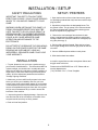
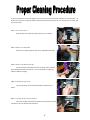
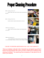
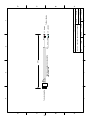
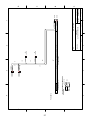
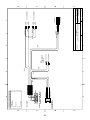
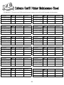
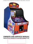
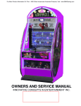
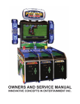
OWNERS AND SERVICE MANUAL
INNOVATIVE CONCEPTS IN ENTERTAINMENT INC.
10123 MAIN STREET, CLARENCE, NY 14031
SERVICE: 1-716-759-0360
FAX: 1-716-759-0884
E-MAIL: [email protected]
WEBSITE: www.icegame.com
TABLE OF CONTENTS
INTRODUCTION…………………………………………..PAGE3 3
INTRODUCTION………………………………………...PAGE
·
·
GAME
FEATURES
• FEATURES
PLAY
•GAME
OPERATION
•
MAINTENANCE / CLEANING
ASSEMBLY………………………………………………...PAGE 3
INSTALLATION
SET-UP…………….………………..PAGE 4 - 5
· BEFORE YOU /BEGIN
·
·
·
·
TOOLS
NEEDED
• SAFETY
PRECAUTIONS
INSTALLATION
• INSTALLATION
• SET-UP A.C.
/ PRINTERS
SETTING
LINE VOLTAGES
•A.C.
ECLINE
CARDVOLTAGE
LOADING ADJUSTMENTS
PRINTER
CLEANING PROCEDURE.………………..PAGE 6 - 7
SET-UP / TESTING
·
SAFETY PRECAUTIONS
·
·
OPTION
MODES
• INTRODUCTION
•TESTING
PROGRAMMING OPTIONS
PROGRAMMING………………………………………..PAGE
8 –16
· PROGRAMMING YOUR GAME
QUICK
TROUBLESHOOTING…………………………PAGE 17
QUICK TROUBLESHOOTING
·
PROBLEMS
• PROBLEMSAND
AND SOLUTIONS
SOLUTIONS
REPAIR…………………………………………..............PAGE
18 –22
REPAIR
·
·
·
·
OPERATIONAL
BACKGROUND
• TROUBLESHOOTING
PHILOSOPHY
REPAIR
•MECHANICAL
REPAIR
• COMPUTER /REPLACEMENT
ELECTRICAL
ELECTRONIC REPAIR
•MAINTENANCE
MONITOR REPLACEMENT
•
•
•
•
•
PRINTER REPLACEMENT
LIGHT REPLACEMENT
PARTSLARGE
LISTINGS
MONITOR REPLACEMENT
SMALL MONITOR REPLACEMENT
CAMERA REPLACEMENT / ADJUSTMENT
SCHEMATICS
PARTS LISTINGS……………………………………….PAGE 23
WARRANTY INFORMATION
SCHEMATICS / WIRING DIAGRAMS………………...PAGE 24 - 28
CLEANING WORKSHEET……………………………..PAGE 29
WARRANTY INFORMATION…………………………..PAGE 30 - 31
ICEDOC EC9001
REVISION E
10-12-07
2
INTRODUCTION
FEATURES
MAINTENANCE / CLEANING
Thank you for purchasing the new and innovative
Chuck E. Cheese Extreme Card Machine™.
This game has been designed to be as trouble and
maintenance free as possible.
This exciting game-style unit creates beautiful and
unique extreme action cards in a flash! Just like
when you get a photo ID, the child simply sits,
smiles. The child then gets to choose which Extreme
Card theme they wish to have. As they watch, the
Extreme Card of their choice is printed right before
their eyes. .
With this in mind the only basics are to keep the
game clean. Below are the main areas to take care
of with specific directions.
The Chuck E. Cheese Extreme Card Machine™ is
easy for customers to use and offers on-screen
instructions in several languages. An enticing
advertising loop and open-style seating encourages
kids to sit right down and try it out.
Warning **
This equipment is not to be used near a water jet. A
water jet should NOT be used to clean this equipment.
Use a soft lint free cloth to clean the plastic. Do
not use ammonia based glass cleaners on clear
plastic surfaces. Doing so will cause the plastic
to fog over a period of time. Any ammonia free
glass cleaner is recommended. Novus (cleaner
#1) makes a special plastic cleaner that reduces
static build up and restores a glass shine back
to the plastic.
OPERATION
Once credited, the voice of Chuck E. will begin
speaking to the child. The game will tell the kids to
choose a ‘boy’ or a ’girl’ card. Using the front panel
buttons the child must select before a card will print.
CABINET
Next, the child will follow Chuck E’s directions and
position his/her face within the circle on the screen.
After a brief countdown a snapshot will be taken for
printing on the card. The child’s image will be printed
on one of (9) gender specific cards. Cards are
ordered in groups of nine.
The cabinet plastic and decals can be cleaned with soapy
water or spray furniture polish. DO NOT use any alcohol
or petroleum based cleaners as they could damage the
plastic or printed parts.
The card will be delivered to the child in one of the
slots depending on gender selection. The boy and
girl card slots are coordinated with the selection
buttons.
COIN MECHANISMS
The coin mechanisms should be cleaned periodically, as
they will accumulate dirt which will cause the coins to
stick.
Remove the coin mech and clean them in a dish detergent solution and a stiff brush. Dry thoroughly and reinstall.
3
INSTALLATION / SETUP
SAFETY PRECAUTIONS
SETUP / PRINTERS
IMPORTANT: FAILURE TO FOLLOW THESE
DIRECTIONS CLOSELY COULD CAUSE SERIOUS
INJURY TO YOU AND/OR DAMAGE TO YOUR
GAME.
1. Open the front door of the unit and remove any protective packaging material that may have been used for shipping purposes.
2. Unpack the printers from the designated boxes. The
boy printer is blue. The girl printer is red. Printers should
be clean and loaded with cards. Proper cleaning procedures are explained on pages 6&7.
WARNING: WHEN INSTALLING THIS GAME, A 3
PRONG GROUNDED RECEPTACLE MUST BE
USED. FAILURE TO DO SO COULD RESULT IN
SERIOUS INJURY TO YOURSELF OR OTHERS.
FAILURE TO USE A GROUNDED RECEPTACLE
COULD ALSO CAUSE IMPROPER GAME
OPERATION AND/OR DAMAGE TO THE
ELECTRONICS.
3. Remove the card carriages from the back of each
printer. Load appropriate gender cards into each printer
carriage. Make sure cards are loaded into carriages properly (see picture pg. 5).
4. Pull the sliding shelves forward. Place the boy printer
on the upper sliding shelf. Place the girl printer on the bottom shelf.
DO NOT DEFEAT OR REMOVE THE GROUNDING
PRONG ON THE POWER CORD FOR THE SAME
REASONS AS GIVEN ABOVE. USING AN
IMPROPERLY GROUNDED GAME COULD VOID
YOUR WARRANTY.
5. Connect USB and power cables to each printer.
6. Slide shelves back into cabinet.
INSTALLATION
It would be a good idea to order extra printer ribbons and
boy/girl cards at this time.
1. To start, please be sure you have a good area to put
your Extreme Card Machine in. This area should NOT be
in direct sunlight, nor should it be in a totally dark area.
While the unit will work under either of these conditions, it
might make it a little more difficult to get the best picture
quality. All of the adjustment parameters are based on
"average" lighting conditions.
Please order all SUPPLIES from I.C.E. Please call our
service department at:
(716) 759-0360 Ext. 3, Parts / Supplies
2. Make sure you have sufficient floor space in the area
where you will do your installation. Be sure you have
enough room so the normal traffic pattern in your location
is not disrupted. Almost all of the maintenance of the unit
may be accomplished through the front door of the game.
Only in rare circumstances will you need to access the
back door of the machine.
3. Inspect the game for shipping damage. Open the rear
door and check all of the connectors on the back of the
computer and be sure they are firmly seated.
4. Push unit into final position.
4
INSTALLATION / SETUP
7. Plug the CEC Extreme Card Machine into an A.C. outlet.
MAINTENANCE & CLEANING
INSTRUCTIONS
8. If the unit does not start when plugged in, turn on the
switch now.
In order to ensure a very high quality of personalization of your plastic cards, every user of an Extreme
Cards’ printer must follow the following maintenance &
cleaning instructions.
9. At this point your Extreme Card Machine should go
through it's initialization routine, and should be ready to
operate in a couple of minutes.
The factory warranty is subject to strict compliance
with ordinary maintenance instructions, and specifically to compliance with the equipment cleaning cycle
intervals.
10. This machine default is set up for 1 coin play. If this is
acceptable, then your machine is ready to vend.
11. To set the game up differently from the factory settings, please refer to the PROGRAMMING section of the
manual.
Failure to comply with the procedures described in this document entails cancellation of the
warranty on your printer and its print head.
ICE will not be liable if the printer is used under non-approved maintenance conditions. A worksheet can be found at the end of the manual to provide
ICE with proof of maintenance.
EC CARD LOADING:
ICE provides you with the following maintenance items,
available under the following reference item:
Make sure proper card loading direction is the same as
below. Picture/ Face area up and out.
EC2010 - Ultra Clean cleaning kit:
- Five cleaning cards pre-saturated with 99% isopropyl
alcohol.
- Five 99% isopropyl-based cotton swabs.
- A dispenser box of 40 pre-saturated cleaning wipes.
Clean the card feed module
Cleaning cycle: every 1000 cards printed
Maximum interval between two cleaning cycles: 1200 printed cards
Maintenance accessory: pre-saturated cleaning cards
Service the cleaning roller
Cleaning cycle: on each ribbon change
Maintenance accessory: cleaning cloths
Clean the print head
Cleaning cycle: at each ribbon change
Maintenance accessory: cotton swab saturated with isopropyl alcohol
5
To keep your Extreme Card‘s print quality at its best you must clean each printer when they reach 1000 prints. To
do this you will need a cleaning kit which contains one print head cleaning swab, one clearing cloth for roller, and
five cleaner cards.
STEP 1: Access the printers
Slide the drawer forward of the printer that you are cleaning.
STEP 2: Remove the card holder
With your two finger pinch the side of the card holder and lift up.
STEP 3: Remove the Ribbon Cartridge
Lift the front left side and back left side of the ink rollers with the
gears attached first and lift up and out. You can discard this if replacing
with new Ribbon Cartridge.
STEP 4: Cleaning the print head
Open the package for the swab and bend the swab halfway as
shown.
STEP 5: Cleaning the print head continued
Move the cleaning swab back and forth across the print head. This
will dissolve any ink dried into the print head.
6
STEP 6: Cleaning the back roller
Open the roller cleaner remove the blue roller located in the back of
the printer.
STEP 7: Cleaning the back roller
Roll the roller back and forth until all debris are removed.
STEP 8: Insert Cleaning Card
Remove cards from stacker and replace with cleaning card. Replace stacker. .
STEP 9: Start Cleaning Cycle
Press and hold button on control panel for 2 seconds. Cleaning
starts when LED light is flashing. Card will eject when cleaning is complete
FAILURE TO PREFORM MAINTENANCE WILL VOID YOUR WARRANTY!
There is a worksheet in the back of the manual that you must photocopy and fill out
every time a cleaning procedure is done. In order to comply with the printers manufacture’s cleaning procedure, this work sheet can be used to prove maintenance was
preformed as directed. You should keep these worksheets in a safe place for the duration of your warranty.
7
PROGRAMMING
D: ACCT - Accounting - Cash Page - Prints the
system accounting picture. Running Totals of gross
and picture count are recorded as well as system
hardware profile and performance.
INTRODUCTION
Programming and making adjustments is simple and
straightforward. All adjustments will be made
through the BOOTH MENU shown below.
E: ACCT - Accounting - Cash Page - no print Same as above (D) only no printout is produced.
Allows user to view the accounting information on
the video monitor.
TO ENTER THE BOOTH MENU PRESS “Q” ON
THE KEYBOARD, WHICH IS LOCATED INSIDE
THE FRONT DOOR UNDER THE PRINTER. THE
UNIT MUST BE RUNNING IN ORDER TO ACCESS
THIS MENU.
F: SETTIME - Set Booth Time & Date.
G: HCS - Adjust Image Quality. Allows owner to
adjust the portrait clarity such as: contrast, hue,
saturation, sharpness, and brightness.
TO EXIT THE BOOTH MENU, PRESS “A” TO
REBOOT.
H: SYSLOG - View System Log. Allows owner to
view an historical record of system activity.
I: CPLOG - Copy System Log to removable media Allows the owner to copy the system log to a floppy
disk. This information will be divided into two files:
Infohut.log and Syslog.txt.
J: TNAILS - Copy Thumbnails - Allows the owner to
copy the system log to a floppy disk.
K: INSTALL - Run Install removable media. Used to
run the Installation Diskette for this program.
L: SHELL - Exit to Linux Bash Shell
M: AUMIX - Sound Utility - This will allow the owner
to make changes in the sound qualities, such as
volume levels, and balance levels.
N: NOOP - Option Not Available.
O: HALT - Shutdown System.
DETAILED DESCRIPTIONS
BOOTH
REBOOT
PROGRAMMING OPTIONS
Press “A” on the keyboard to save any changes and
reboot the system. You must press “A” in order to
exit from the BOOTH MENU.
BOOTH MENU
A. REBOOT - Returns user to the Portrait Mode of
operation by REBOOTING the computer. The
computer will go through its initialization routine
upon start-up.
Upon REBOOT, the computer will run through its
initialization tests. Once initialization is complete,
the unit will be ready for normal operation or other
programming through the BOOTH MENU.
B: SYSCFG - System Configuration Utility– Allows
owner to set up site and system specific parameters.
C: NOOP - Option Not Available.
8
PROGRAMMING
BOOTH
System Configuration Utility
(SYSCFG)
There are many user options available in this menu, however, only certain options will ever need to be
adjusted.
9
PROGRAMMING
SYSCFG MENU DETAILED DESCRIPTIONS
(FROM TOP OF MENU TO BOTTOM)
(SEE PHOTO OF SYSCFG MENU ON PREVIOUS PAGE)
In the following descriptions, objects in [brackets] are the factory default settings, set up for the type of
installations used on this unit. Objects in {parentheses} indicate the function key necessary for editing that
particular field.
Machine Number: This is the ID of the booth.
Country: TOKEN_D/M/Y
Location: Type in a location name. (Max 20 Characters.)
State: Enter the State Initials, if applicable.
Type of Vend: [$2-2] Use {F2} to highlight the correct vend price and hit {ENTER} to select.
Save Thumbnails: [No] DO NOT CHANGE THIS OPTION. IT SHOULD ALWAYS BE SET TO NO.
Setting this option to Yes may cause your Hard Drive to malfunction.
Bill Acceptor Model: None
Accept Scrip: No
Daily Service Hours: [24] Enter the number of hours the booth will be turned on over a 24 hour period.
Coin Acceptor: NRI
DIO Base: 0 X 300
Accept Credit Cards: [No] Applicable to installations utilizing a card swipe unit. Use the {spacebar} to toggle
Yes or No.
Accept Tokens: [No] Only used when applicable. Use the {spacebar} to toggle Yes or No.
Print Stickers: [No] How Many: 16
Courtesy Vend: [No] Applicable when installed with the courtesy vend button. Use the {spacebar} to toggle
Yes or No.
Used when applicable, in conjunction with an installed bill acceptor. It should be set to Yes if a bill acceptor is
installed, and set to No if no bill acceptor is not installed.
Processor Type: [NORMAL] DO NOT CHANGE THIS OPTION. Changing this option may cause your
booth to malfunction.
Printer Use: [Parallel] This option has been factory set for the type of printer port used.
other option available, parallel, is not used.
The
User Timeout: 360 Seconds
Camera Input: [Composite] Use the {spacebar} to toggle the camera input type. Options are: Composite, SVideo, & RGB.
10
PROGRAMMING
Control Panel Style: [MENU BUTTONS] Use the {spacebar} to toggle either PICTURE BUTTONS or MENU
BUTTONS for the style used on the control panel.
Extron Box: [No] NOT USED.
Lights: [UIB] Use {F2} to select the port used for the lights. Available Options are: 0x378, 0x278, 0x3BC,
UIB, DIO.
Number of Pictures: [2]
Premium Vend: [No] NOT USED.
Protection Block: [LPT1] Location of the Dongle on the PC. DO NOT CHANGE THIS OPTION. Changing
this option may cause your booth to malfunction.
Paper Size: [Letter] Use {F2} to choose the paper size used in the unit. Available Options are: Letter, A4,
Legal, A5.
Use Scanner: [No] Use the {spacebar} to toggle whether a scanner is installed. Options are Yes or No.
Email Enable: [No] Use the {spacebar} to toggle whether the email feature is enabled. Options are Yes or
No.
Generate Ads 7 & 8: [No] Use the {spacebar} to turn 22 graphic ads on or off. Options are Yes or No.
Video Overlay: [Overlay] Use {F2} to select the video overlay style. Options are: Overlay, Chromakey, or
Sandwich.
Improve Quality: Yes
Multiple Languages: [No] Use the {spacebar} to toggle whether or not to give customers multiple language
instructions. Options are Yes or No.
Primary Language: [English] Use {F2} key to choose from the list of available languages (as shown in the
previous option,) which one to use as the Primary Language.
Soundcard Installed: Yes
Sound-Only: Yes
Type: 0X2
Picture Path: [/vend/pics/] NOT USED
Vend Base Path: [/vend/] NOT USED
Out of Film Tele #1: 1-888-FOR-FOTO
Out of Film Tele #2: (1-888-367-3686)
Installed Printer: Evolis Pebble 3 badge
Standup Booth: [No] Use {spacebar} to toggle whether this is a standup booth. Options are Yes or No.
Zoom Buttons: [No] Use {spacebar} to toggle whether there are any Zoom buttons. Options are Yes or No.
Red Arrows: [No] Use the {spacebar} to toggle whether there are red arrows above the monitor. Options are
Yes or No.
11
PROGRAMMING
Freeze Countdown: [Yes] NOT USED.
CP710 Paper Size: [Large] NOT USED.
Number of Poses: [1] Press {F2} to select the number of poses a customer may have. Options are 2 or 3.
Video Standard: [NTSC] Press {F2} to bring up a list of Video Standard formats. Options are: Default,
NTSC, PAL. This setting should not be changed.
Mirror Image: [No]
Video Card: [FBSpectrim] Press {F2} to bring up other options for this setting: Flashbus, Flashpoint, Targa,
VIGA, XII, None. Has been factory set to the correct video card installed in this unit.
Up / Down Buttons: [No] Use {spacebar} to toggle whether the unit has Up and Down buttons installed.
Options are Yes or No.
Print Duration: 0
Wireless Pager: No
Has Freeze Button: [No] NOT USED.
Transfer Option: [No]
Shared Up & Down: [No] Use {spacebar} to toggle whether the unit has Up and Down buttons installed.
Options are Yes or No.
12
PROGRAMMING
OPTIONS D & E
ACCOUNTING-CASH PAGE
(ACCT)
From the BOOTH MENU, pressing either D or E will get you to the Accounting information. When you press
either D or E, you will first be required to enter your initials using the keyboard. This information will be stored
on the SYSTEM LOG for future reference.
If you would like a PRINT OUT, Press D, If you would like to view the information ON-SCREEN, with no print
out, Press E. A sample of the accounting information given is shown below:
Top area of the Accounting Screen:
Date= Current Date & Time
Last= Date the last accounting was taken
Sys= Manufacturer Kiosk Number
ICE= Location as entered in SYSCFG Menu.
The Number on the right is the Software version ID#.
Efficiency Graph:
(Designated by the
letter”E”)
The efficiency
number is indicated
by the left column
(0-100) number
scale.
The Daily Sales
are indicated by a
vertical bar graph,
with a total sales
number at the top
of each bar.
The gray vertical
bars represent the
weekend dates.
SW1: Number of people
who selected the Classic
Portrait after reviewing
available choices.
SW2: Number of people
who selected the Classic
Portrait after the Caricature
was finished.
Avg: shows the 14
day picture
average.
B: Number of people who
selected both a Caricature
and a Classic Portrait.
BIL = Bill Acceptor
FLM = Film
PRN = Printer
POW = Power
OTH = Other
D: Display Type– BTTV / TV
Tuner
P: Printer Type–LA=LASER
Prints= Number of pictures taken to date.
Shots Left= Number of Photo shots
(Used in color booths only)
available.
S: Sound Enabled Y/N
Cash= Total money count, (used for
ML: Multi Language Y/N
accounting.)
Free= Dollar value of free vends given.
L: Languages Enabled:
0= English
5= German P:= # of PLAYS
1= Spanish
6= Atlus
S: SINGLES= # of single vend sessions.
2= French
7= Dutch
D: DOUBLES= # of double vend sessions.
3= Japenese 8= Italian
EM:= Efficiency for the Month calculated as
4= Portuguese
follows: Time in rotation ÷ (# of days x daily
V: Type of Vend:
service hours), (per setting in SYSCFG
Available options are:
Menu.)
$1, $1-1, $1-3, $1-5, $2, $2-2-2, EY:= Efficiency Year to Date.
$2-2, $3, $3-3, $4, $4-2, $4-3,
$5, $5-3, $5-4, $5-5, $6, $1-2+, ON:= Number of hours the booth is set up for
in “Daily Service Hours” in SYSCFG Menu.
$1-3+, $1-4+, $2-3+, $2-4+.
DI: Digital I/O Board Y/N
13
Fault Report Profile:
A 14 day history of reported “down time”
and the responsible component.
The Right most column represents the
previous day’s date.
The Left most column represents 14
days prior.
Each time the booth is down a number
will increment in the appropriate column.
In the power column, a “1” will be
displayed each day to reflect the on/off
timer.
NOTE: If an error occurs more than 9
times in a 24 hour period, a * will be
displayed.
PROGRAMMING
Using the CONTROL PANEL on the front of the
booth, press the SELECT button to DECREASE the
intensity level for each setting above. Press the OK
button to INCREASE the intensity level for each
setting above.
OPTION G
ADJUST IMAGE QUALITY
(HCS)
Proper adjustment of Image Quality settings on the
Sketch Express™ is essential to guarantee that the
product delivered is pleasing and consistent for the
customers. Sometimes Ambient lighting conditions
(brighter or dimmer than normal) can have an effect
on image quality This option will fine-tune that
quality.
When you are satisfied with your selections, press
“3” to SAVE your settings. If you are not satisfied,
and wish to discard your settings, press “4” to QUIT
WITHOUT SAVING.
OPTION H
VIEW SYSTEM LOG
(SYSLOG)
It is important to run several tests after adjusting any
of the image qualities to make certain that any
changes corrected the image qualities without
causing any harm.
This option allows you to view an historical record of
system activity. It gives information such as: how
many times the computer has been rebooted, how
many times the file check has been run, what are
the dates of the last file check, etc. Press “Q” to exit
SYSLOG.
Pressing G from the BOOTH MENU will bring you to
the menu screen shown below. This menu only
displays the proper key you will use when adjusting
the Image Quality for each item listed. You may
wish to write down this information or refer to this
manual when adjusting the Image Qualities.
OPTION I
COPY SYSTEM LOG TO FLOPPY
(CPLOG)
This option is used to copy the System Log
Information (Option H) to a floppy disk. It will divide
the information into two files: Infohut.log and
Syslog.txt.
If you enter this option in error or do not have a
floppy disk, you will get an error message, and
should press enter to return to the BOOTH MENU.
h - HUE: = Shade of Color or Tint
s - SATURATION: = Strength of Color or Tint
t - CONTRAST: = Variation of Lightness &
Darkness of image
l - BRIGHTNESS: = Distribution of Light
u - SHARPNESS: = Focus
OPTION J
COPY THUMBNAILS TO FLOPPY
(TNAILS)
SINCE “SAVE THUMBNAILS” SHOULD BE SET TO
“NO” IN THE SYSCFG MENU, DUE TO POSSIBLE
MALFUNCTION, THIS OPTION IS NOT USED.
NOTE: The recommended order for the above
adjustments is: Contrast, Saturation, Hue, and
Brightness. Sharpness or Focus should be adjusted
last, as needed.
OPTION K
RUN INSTALL FLOPPY
(INSTALL)
After the above menu appears, you are prompted to
press any key to continue, at the bottom of the
menu.
This option is only used for the program’s initial
installation into the computer. It has been factory
installed, therefore this OPTION is NOT USED.
Press any key, (the spacebar will do,) and you will
see what the camera sees, on the screen in front of
you.
14
PROGRAMMING
OPTION L
Audio Mix Adjustments
EXIT TO LINUX BASH SHELL
(SHELL)
BE VERY CAREFUL IN THIS MODE TO PREVENT
UNDESIRED RESULTS. Although there is nothing
you can hurt, you might change an adjustment that
will cause unexpected results.
CAUTION: THIS OPTION SHOULD ONLY BE
USED WHEN DIRECTED BY AN ICE
TECHNICIAN.
On the left side of the Audio Mix Menu, you will find
the words Quit, Load, Save, Keys, Mute, Only, &
Undo. (The first letters are highlighted in Pink.)
Linux is the Operating System used by the unit to
run its program. You are required to provide a user
name and password to enter the Linux Bash Shell.
Use the keyboard and the highlighted letters to
perform tasks in this menu, such as: “Q” to Quit the
menu, “L” to Load default Volume Levels &
Balances, “S” to Save new settings, “K” to show
action Keys used to change settings in this menu,
“M” to Mute the sound, “O” to Only change one
particular setting, and “U” to Undo any changes you
wish to abandon.
You should have a working knowledge of a Linux
system before accessing this file.
Linux is a case sensitive system. If a file or directory
has any capital letters, you must use the exact case
to access that file or directory. (Example: “myfile” is
not the same as “Myfile” or “MYFILE”.)
These center items are the options you may change:
Vol=Volume, Synth=Synthesizer, Pcm= PC Music,
Spkr=Speaker, Line = Line.
All commands are lower case.
Username: vend
Password: fotofant
Center Items that are NOT USED and cannot be
adjusted at all: Mic, CD, Rec & Line 2.
Type “EXIT” to exit the Linux Bash Shell.
(Also, see “FSCK ERROR MESSAGE” at the end of
the PROGRAMMING section of this manual.)
The only parameter you may need to change in this
menu is the Volume levels. (Top Center). Use the
Left / Right Arrow Keys to make changes to the
Volume Levels (on Left Side) and Balance Levels, if
necessary, (on Right side).
OPTION M
SOUND UTILITIES
(AUMIX)
Once you are satisfied with the changes you have
made use “S” to save the changes or “U” to undo
changes. Press the “Q” key to quit this menu.
Pressing “M” from the booth menu will allow you to
adjust the sound qualities of the system, (FROM
THE SOUND CARD OF THE COMPUTER), such as
volume levels and balance levels.
If you find that you have made an incorrect
adjustment, simply go back into the Aumix Menu
and press “L” to Load the factory default settings for
all options in this menu.
NOTE: You can make additional changes to the
SKETCH EXPRESS™ Master Volume by adjusting
the “output level” dial on the audio amplifier, which is
located under the printer.
The AUDIO MIX Menu appears below:
15
PROGRAMMING
OPTION O
FSCK ERROR
SHUTDOWN SYSTEM
(HALT)
(File System Check Error)
If an error occurs during the file system check or
initialization routine, you will most likely be dropped
into the Linux Bash Shell to repair it.
Use this option to take this unit out of service for any
length of time. This option will shut down the
computer system properly for moving, storage, etc.
Be sure to shut off the main power switch, as
described in the set-up section of this manual.
In this case, the system will give a message that
says: Give root password for maintenance, (or
type CONTROL D for normal startup.)
When the unit is ready to put into service again,
simply plug the unit into a grounded outlet, and turn
the main power switch on and let the computer run
through its initialization routine. If no errors occur
during initialization, the unit is ready for normal
operation or programming optional settings from the
BOOTH MENU.
These types of errors are quite common in Linux
based computers. The computer is having trouble
putting files where they need to be for startup.
By following the instructions below, you can tell the
operating system to decide on its own the best place
for files. The instructions are case sensitive and the
commands must be entered exactly as instructed.
Every space counts. If one space is wrong, the
operation will fail.
1. The first step is to reboot the computer and let it
freeze back up at the fsck error screen.
2. Next, you need to enter the password in lower
case letters. Type: fotofant.
3. Then hit enter.
4. Now you should be at a c:vend type of command
prompt. From here, you need to type exactly:
5. fsck –y /dev/hda1. (Make certain to include the
space between the “k” and “-”, and between the
“y” and the “/”. Also, that’s a 1 not an L at the
end.)
6. Then hit enter.
7. You may get a message that says “running fsck
on a mounted file system, may cause severe
damage.” And, “Do you want to continue? (y/n).”
If so, press y to continue the file system check.
8. Type the word reboot at the command prompt
and the booth should come up into the vending
mode.
9. If the system does not come back into the
vending mode, retry the steps again, making
sure that you are typing exactly what is shown,
including all spaces.
16
QUICK TROUBLESHOOTING
MACHINE WILL NOT ACCEPT MONEY
• Bad or sticky coin mech - Clean and adjust mech as necessary.
• Bad Harnessing - Check with meter and repair if necessary.
• Bad or Dirty Dollar Bill Validator - Clean unit then test. Replace if necessary.
• Bad Computer - Replace.
NO PICTURE OR BAD PICTURE ON MONITORS
• Bad Monitor - Replace Monitor.
• Bad Harnessing - Test and Repair or Replace Monitor.
• Bad Computer - Replace Computer.
• Monitor Adjusted Improperly - Readjust Monitor.
MACHINE WILL NOT PRINT CARD
• Printer OUT OF CARDS - Add cards, and restart Computer.
• Printer tray not seated properly. Re-seat tray and restart computer to initialize.
• Printer Jammed - Clear Jam and reinitialize as shown in the repair section of this manual.
• Printer off line - Reinitialize as shown in the repair section of this manual.
• No power to printer or printer turned off - Check power or turn printer on, reboot computer.
• Printer Cable bad or loose - Check cable and reseat or replace as necessary.
• Computer bad - Repair or replace as necessary.
NO SOUND FROM MACHINE
• Sound Volume turned down - Enter programming mode and check volume level (see programming).
• Speaker bad or disconnected - Check for proper connection and replace if necessary.
• Audio amplifier disconnected or bad - Check amp and connections and replace if necessary.
• Audio amplifier output level set too low - Check output level adjusting pot on amp.
• Computer program trashed or frozen - Restart computer to initialize.
MACHINE WILL NOT RUN PROGRAM PROPERLY
• Check settings in sysefg.
• Computer bad - Check and repair or replace as necessary.
• Harnessing bad or disconnected - Check and repair or replace as necessary.
PRINT QUALITY POOR - PICTURE EITHER TOO DARK OR TOO LIGHT
• Machine set up in an area that is either too dark or too light (by a window). Move if possible or adjust
settings in HCS screen.
• Camera settings improper - reset according to set up directions in programming section of manual.
• Built in Florescent lighting burned out - Replace burned out light bulbs.
• Harnessing or power to bulbs not working - check and repair as necessary.
TRIPLE IMAGE IS SHOWN AND PRINTED WHEN COMPUTER OR MONITOR IS REPLACED
• From the shell, type “chmonitor” without the quotes and then select option B. Reboot computer.
17
REPAIR PROCEDURES
NOTE: THE CEC EXTREME CARD MACHINE
MONITOR WILL SHOW “ PLEASE CALL
ATTENDANT” IF THE PRINTERS ARE OUT OF
CARDS, OR IF THE GAME HAS SOME OTHER
TYPE OF ERROR. THIS IS DONE SO THAT THE
OPERATOR IS MADE AWARE OF A POSSIBLE
PROBLEM, BUT THE CUSTOMER WILL NOT GET
A SENSE OF UNRELIABILITY.
REPAIR
Repairs will be pretty much straight forward, with
most being limited to the actual replacement of bad
components.
WARNING: ALWAYS REMOVE POWER TO THE
GAME BEFORE ATTEMPTING ANY SERVICE,
UNLESS NEEDED FOR SPECIFIC TESTING.
FAILURE TO OBSERVE THIS PRECAUTION
COULD RESULT IN SERIOUS INJURY TO
YOURSELF OR OTHERS.
TROUBLESHOOTING
PHILOSOPHY
To find problems with your CEC Extreme Card
Machine always first check what should be obvious.
See that the machine is plugged in, and that all of
the fuses in the game are good.
Next, check to see that all of the connectors are
firmly seated and that none of the wires have been
pulled out of them.
When trying to find out if specific components are
bad or not, try swapping them with components from
another CEC Extreme Card Machine (If you have
one), to see if the problem moves with the machine,
or stays where it was. This will help you to know if
you have a problem with a specific component, or
maybe a problem with either the wiring or the
computer.
Use extreme caution when using probes or
voltmeters if the game is powered up. If doing
continuity checks, it is important to disconnect the
harnessing at both ends, as attached they may yield
erroneous results.
If a Computer is suspected as the cause of a
problem, check to see that all of the components
and boards are firmly attached to the Main Board.
Pay special attention to any socketed devices.
If light bulbs are suspected, swap them with one that
is known to work to narrow the problem down to
either a bulb or P.C. Board.
18
REPAIR PROCEDURES
COMPUTER REPLACEMENT
1. To replace the computer, first, shut off and
unplug the machine.
2. Pull the machine away from the wall and unlock
and open the back access door.
3. Remove all of the connectors to the back of the
computer CAREFULLY noting the locations of all
of the connectors. You may wish to mark each
wire for replacement later.
NOTE: ONE OF THE MOST COMMON FAILURES
IN PC COMPUTERS IS INTERNAL COMPONENTS
AND CONNECTORS BECOMING LOOSE.
CAREFULLY CHECK THAT ALL CONNECTORS
AND BOARDS ARE FIRMLY SEATED.
THE SECOND BIGGEST FAILURE IS COOLING
FAN FAILURES LEADING TO OVERHEATING OF
THE PROCESSOR, ETC. CHECK THAT ALL FANS
ARE WORKING PROPERLY. IF NOT, REPLACE
IMMEDIATELY AND SEE IF THE MACHINE WILL
THEN WORK PROPERLY.
4. Loosen and remove the 2 straps that retain the
computer to the cabinet. One strap is locater
across the top rear of the computer and the
other over the top front of the computer.
6. Replace in the reverse order.
7. If the computer is replaced, check to see that the
new one is programmed properly. Please refer to
the programming section of the manual.
5. Open the front door and pull the lower door
open. It will be much easier to remove the
computer from the front of the cabinet.
19
REPAIR PROCEDURES
FLUORESCENT DOOR LIGHT
REPLACEMENT
1. Open the front door of the game.
2. Remove the (4) retaining nuts from the light
cover.
3. Remove the bulb, and replace with new bulb of
same wattage and style.
4. Re-assemble in the reverse order.
LARGE MONITOR
REPLACEMENT
1. Remove (8) monitor cover screws and (2)
camera cover screws from the rear of the
monitor cabinet.
2. Remove the front cover and bezel and set in a
safe location. Be careful not to scratch the
monitor cover.
3. Remove the (4) side screws that attach the
monitor to the monitor cabinet.
4. Remove the monitor from the cabinet.
OVERHEAD MARQUEE LIGHT
REPLACEMENT
5. Remove all power and signal cables from the
underside of the monitor.
6. Re-assemble in reverse order.
1. Unplug CEC Extreme Card Machine and
disconnect power cord.
7. Adjust the new monitor as necessary.
2. Remove (6) screws on right side of marquee
case.
3. Remove bottom (2) screws on support side of
marquee case in order to remove bottom casing
piece.
4. Slide acrylic decal cover down and out of slot in
order to expose light bulbs.
5. Make sure bulbs have cooled before removing.
6. Remove bad bulb, and replace with new bulb. It
is highly recommended that same model bulb is
used for replacement
7. Reassemble in reverse order.
20
REPAIR PROCEDURES
PRINTER REPLACEMENT
1.
Open front door of the game.
2.
Slide shelf of printer to be replaced out towards
CAMERA REPLACEMENT /
ADJUSTMENT
1. Remove (2) back camera housing cover screws
in order to expose camera connections.
the front of the game.
3.
2. Unplug video and power cables in order to free
the camera housing from the monitor cabinet.
Unplug the power and USB cables from the side
of printer.
4.
Lift straight up on printer, as the legs of printer
sit down in fitted holes.
5.
Replace in reverse order.
IFTHE PRINTER DOESN'T WORK, REVIEW THE
INSTALLATION PROCEDURE.
DOUBLE CHECK TO BE SURE THAT YOU HAVE
CARDS IN THE PRINTERS AND THAT THE CARD
CARRIAGE IS FULLY SEATED IN THE PRINTER.
TURN THE GAME OFF AND ON AGAIN AND
RETRY. IF THE PRINTER STILL DOESN'T WORK
CALL OUR SERVICE DEPARTMENT FOR
ASSISTANCE.
21
REPAIR PROCEDURES
3. Remove the (6) nuts that hold the camera
housing in place.
NOTE: PLEASE NOTE THE ANGLE THAT THE
CAMERA IS POSITIONED AT. RE-INSTALL THE
NEW CAMERA TO THIS POSITION.
4. Remove screws that holds camera to housing.
5. Remove camera from housing.
6. Replace camera if necessary.
7. Re-install in reverse order.
NOTE: THE CAMERA CAN BE ANGLED UP OR
DOWN TO ACCOMMODATE YOUR AVERAGE
CUSTOMERS’ HEIGHT MORE CLOSELY.
LOOSEN THE NUTS AND ADJUST AS
NECESSARY.
For all other questions about the CEC Extreme Card
Machine you have purchased, kindly contact us:
I.C.E. SERVICE DEPARTMENT
716-759-0360
NORMAL BUSINESS HOURS ARE:
MONDAY – FRIDAY 9:00 AM TO 6:00 PM
22
PARTS LISTING
MECHANICAL PARTS
5014
CG5014
EC1051
EC3026
EC3028
SE1013
GRAPHICS
LOCK (7/8” CAMLOCK)
T HANDLE (LOCK)
MAGNETIC CATCH
LARGE MONITOR COVER GLASS
MARQUEE GLASS
LOCK CAM
EC7003
EC7004
EC7005
EC7006
EC7014
EC7015
BOTTOM
EC7016
EC701EC7025
EC7026
EC7027
HARDWARE & MISC.
EC2009
EC2010
EC9001
EVOLIS BLACK INK CARTRIDGE
ULTRACLEAN CLEANING KIT
SERVICE MANUAL
ELECTRICAL / ELECTRONIC
PARTS
8453
8545
8730
8690
CL2005
CS8449X
E00049
E02258
E02970
EC2000
EC2001
EC2003
EC2004
EC2005
EV2009
FP2007
MON19LCDV
SH2130X
TS2033X
BULB PL-L 18W/30
BULB COMPACT FLOURESCENT
CAMERA SONY FCB-IX45C
FLUORESCENT BULB
BUTTON (LARGE SQUARE)
BALLAST ASSEMBLY
LED WEDGE BASE
FUSE 5 AMP SLO BLO
SWITCH PUSH/PULL
EC COMPUTER
EVOLIS PEB3LE PRINTER (BLUE)
EVOLIS PEB3LE PRINTER (RED)
EVOLIS CARD HOLDER (BLUE)
EVOLIS CARD HOLDER (RED)
AUDIO POWER AMP
SPEAKER 4” ROUND
MONITOR 19”LCD VGA
BULB SOCKET MARQUEE
PCBA (TRANSISTOR) FOR COIN
COUNTER
23
DECAL - INSET TOKEN HERE
DECAL - DOOR
DECAL - BOY BUTTON
DECAL - GIRL BUTTON
DECAL - LEFT SIDE PANEL TOP
DECAL - LEFT SIDE PANEL
DECAL - RIGHT SIDE PANEL
DECAL - SEAT BACK
DECAL - CABINET TOP
DECAL - MARQUEE SIDE
EC - MARQUEE
4
3
8545
BROWN
G/Y
BLUE
1
2
3
1
2
3
2
1
8545
BROWN
G/Y
BLUE
BROWN
G/Y
BLUE
SH2130X
BALLAST
#CS8449X
BLACK
GREEN
WHITE
1
2
3
1
2
3
BROWN x 2
G/Y x 2
BLUE x 2
SH2130X
CAMERA
#EC1014X
D
1
2
3
1
2
3
EC2051X
E02109
BROWN
G/Y
BLUE
D
EC2056X
19"
LCD MONITOR
#MON19LCDV
PP250X
8453
VGA CABLE
LCD POWER CORD
BROWN x 2
G/Y x 2
BLUE x 2
EC2058X
1
2
3
1
2
3
BROWN
G/Y
BLUE
CHERRY SWITCH #E02970
N.C.
BROWN
G/Y
BLUE
1
2
3
1
2
3
BROWN
G/Y
BLUE
COMM
N.O.
EC2058X
8545
1
2
3
1
2
3
BLACK
GREEN
WHITE
EC2054X
BROWN x 2
G/Y x 2
BLUE x 2
SH2130X
BOY
BUTTON & LIGHT
#EC2001
PRINTER
1
2
3
black
POWER CABLE
USB CABLE
0000000000
RED
BLACK
1
2
3
POWER CABLE
USB CABLE
B
1
2
3
LED BULB
#E00049
black x 2
BLACK x 2
GREEN x 2
WHITE x 2
orange
yellow/red
COIN
SWITCH 1
EC2054X
EC2050X
EC2050X
B
#EC2006
STACKER
black/white
white/brown x 2
BLACK
GREEN
WHITE
GIRL
BUTTON & LIGHT
black
1
2
3
#EC2003
PRINTER
white/brown
COIN
SWITCH 2
EC2051X
orange
yellow/black
CL2005
BLACK x 2
GREEN x 2
WHITE x 2
12V COUNTER
#PC20224
violet/blue
VGA CABLE
orange x 2
yellow/blue
LED BULB
#E00049
EC2050X
black
EC2054X
orange
BLACK
GREEN
WHITE
#EC2004
STACKER
black x 2
COIN LAMP
#161 BULB
E02109
orange x 2
1
2
3
COIN LAMP
#161 BULB
C
BLACK x 2
GREEN x 2
WHITE x 2
C
1
2
3
violet/red
BROWN
G/Y
BLUE
CL2005
E02109
VGA CABLE
EC2051X
EC2051X
FUSE
EC2053X
SX2036X
#XFE02.003075
COMPUTER
1
2
3
4
5
6
7
8
9
15 PIN D-SUB
15 PIN D-SUB
VGA PLUG
gray/red
gray/blue
black x 2
white/brown
5
black x 2
9
gray/black
GROUND
SX2055X
1
2
3
1
2
3
4
3
2
24
1
2
3
1
2
3
BROWN
G/Y
BLUE
BLUE
EC2057X
BROWN x 2
G/Y x 2
BLUE x 2
POWER ENTRY MODULE
NB2007X
USB CABLE
BLACK
GREEN
WHITE
BROWN
AC (L)
AC (N)
USB CABLE
EC2059X
GREEN/YELLOW
FG
1
2
3
EC2050X
orange x 3 & red
- 5 VOLTS (NOT USED)
3A MDQ
E02109
black x 4
GROUND
+ 12 VOLTS
BROWN x 2
G/Y x 2
BLUE x 2
BROWN x 2
G/Y x 2
BLUE x 2
black
E08463
brown/gray
violet/blue
violet/red
black/white
red/gray
AUDIO
JACK
GIRL
USB
1
2
3
4
5
6
7
FP2007
CAMERA
VIDEO
yellow/black
yellow/red
yellow/blue
gray/red
gray/blue
gray/black
black x 2
A
BOY
USB
7
1
2
9 PIN D-SUB
AUDIO AMP
#EV2009
5
+ 5 VOLTS
POWER SUPPLY
#UC2010
1
2
3
1
2
3
4
25 PIN D-SUB
orange
black
red
black
black/white
EC2050X
EC2050X
POWER CORD
#CG2027
1
I
O
A
25
A
B
C
D
8
15
7
14
6
5
4
13
4
4
11
3
10
2
#2407
#2407
12
9
1
green
white
red
black
#2850 - 4 COND
3
#2698 - 15 PIN D SUB PLUG SOLDER CUP
#2690 - CABLE CLAMP
#2407 - RES 100 OHM 5% 1/4W CF
STRIP 1"
82 "
3
DATE
2
DESCRIPTION
TITLE
STRIP 7 "
CUT 2-1/4 " OFF
WHITE AND GREEN
2
#653T
.250
green
7/9/01
REVISED
3/14/02
#SE2061X - BUTTON INPUT HARNESS
black
no
nc
green
PAGE
DRAWN BY
1
red
10 OF 17
MMARTIN
SE.VSD
white
(TWO PEOPLE)
(ONE PERSON)
no
nc
FILENAME
com
BUTTON
COMMON
N.O.
N.O.
COMMON
Sketch Express
#653T
.250
#653T
.250
red
white
#653T
.250
black
com
BUTTON
1
A
B
C
D
26
A
B
4
To Audio Amplifier
RED
BLACK
YELLOW
TITLE
BLACK
#653
Ground
3
* EXISTING HARNESS PROVIDED WITH
AUDIO AMPLIFIER
DATE
2
DESCRIPTION
+ 12 VDC
7/9/01
REVISED
3/14/02
1
PAGE
DRAWN BY
FILENAME
To Power Supply
Sketch Express
#2700
#SE2066X - AMP POWER HARNESS
RED + YELLOW
SE.VSD
13 OF 17
MMARTIN
A
B
C
26 "
1
C
2
D
3
D
4
27
A
B
C
D
4
#E08627 - PLUG COAXIAL
DC POWER PLUG
.110 #E00650
.110 #E00650
.110 #E00650
.110 #E00650
black
* ALL PLUGS ARE SOLDERED TIP
POSITIVE
orange or red
To Camera
4
3
3
6"
88"
60"
.250
#E00653T
.250
#E00653T
DATE
2
DESCRIPTION
TITLE
3 conductor 22 AWG
orange x 2
17"
orange x 2
16"
6"
CUT GREEN OFF
E02056
77"
orange x 2
black x 2
orange
black
2
1/15/07
REVISED
2/21/07
EC2051X
DC POWER HARNESS
MINI STUFFER
1
PAGE
DRAWN BY
2 OF 2
NBRANCATO
EC1000X.VSD
#E00653
#E00653
FILENAME
black x 2
orange & red
1
A
B
C
D
28
A
B
C
D
5
9
4
8
3
7
2"
2
6
1
DB9
To: Transistor
PCB #TS2033X
1
2
3
4
3 PIN CAP #2288
FEMALE #2102
white/black
black x 2
white/red
#E02614 - 9-PIN D SUB MALE
#E02878 - CLAMP KIT
To Computer
9-PIN D-SUB CONNECTOR KEY
1: black x 2
2: white/brown
3:
4:
5: black x 2
6:
7:
8:
9: white/black
4
15 "
3
11 "
36 "
82 "
3
black
red
#E00653
#E00653
GND
+5V
To:
Power Supply
#UC2010
DATE
2
DESCRIPTION
TITLE
37"
2
1/15/07
5v COUNTER
0000000000
REVISED
2/21/07
1
PAGE
DRAWN BY
FILENAME
EXTREME MACHINE
#EC2053X
COIN DOOR/COUNTER HARNESS
1 OF 2
NBRANCATO
EC1000X.VSD
To Coin Switch
To Coin Switch
#HD20224
.250
#E00653T
black
black
red
.250
#E00653T
white/brown
#E02558
.250
#E00653T
black x 2
white/red
red
6"
.250
#E00653T
white/brown x 2
1
A
B
C
D
**WARNING ** Do not exceed 1200 prints between cleaning or you will void all warranties for the printer.
Description
√ OK
Date completed
Total Prints
Description
Print Head Cleaning
Print Head Cleaning
Back Roller Cleaning
Back Roller Cleaning
Automatic Cleaning
Automatic Cleaning
Description
√ OK
Date completed
Total Prints
Description
Print Head Cleaning
Print Head Cleaning
Back Roller Cleaning
Back Roller Cleaning
Automatic Cleaning
Automatic Cleaning
Description
√ OK
Date completed
Total Prints
Description
Print Head Cleaning
Print Head Cleaning
Back Roller Cleaning
Back Roller Cleaning
Automatic Cleaning
Automatic Cleaning
Description
√ OK
Date completed
Total Prints
Description
Print Head Cleaning
Print Head Cleaning
Back Roller Cleaning
Back Roller Cleaning
Automatic Cleaning
Automatic Cleaning
Description
√ OK
Date completed
Total Prints
Description
Print Head Cleaning
Print Head Cleaning
Back Roller Cleaning
Back Roller Cleaning
Automatic Cleaning
Automatic Cleaning
Description
√ OK
Date completed
Total Prints
Description
Print Head Cleaning
Print Head Cleaning
Back Roller Cleaning
Back Roller Cleaning
Automatic Cleaning
Automatic Cleaning
29
√ OK
Date completed
Total Prints
√ OK
Date completed
Total Prints
√ OK
Date completed
Total Prints
√ OK
Date completed
Total Prints
√ OK
Date completed
Total Prints
√ OK
Date completed
Total Prints
Warranty
I.C.E warrants all components in the CEC Extreme Card Machine game to be free
of defects in materials and workmanship for a period of ninety days from the date of
purchase.
This warranty does not cover items damaged due to normal wear and tear,
subjected to abuse, improperly assembled by the end user, modified, repaired, or
operated in a fashion other than that described in the service manual.
If your CEC Extreme Card Machine game fails to conform to the above-mentioned
warranty, I.C.E.'s sole responsibility shall be at its option to repair or replace any
defective component with a new or remanufactured component of equal to or
greater O.E.M. specification.
I.C.E. will assume no liability whatsoever, for costs associated with labor to replace
defective parts, or travel time associated therein.
I.C.E.'s obligation will be to ship free of charge, replacement parts by U.P.S.
Ground, U.S. mail, or other comparable shipping means. Any express mail or
overnight shipping expense is at the cost of the purchaser.
Products will be covered under warranty only when:
·
The serial number of the game with the defective parts is given.
·
The serial number of the defective part, if applicable, is given.
·
Defective parts are returned to I.C.E., shipping pre-paid, in a timely fashion, if
requested by I.C.E.
·
A copy of the sales receipt is available as proof of purchase upon request of
I.C.E.
I.C.E. distributors are independent, privately owned and operated. In their
judgment, they may sell parts or accessories other than those manufactured by
I.C.E. We cannot be responsible for the quality, suitability, or safety of any nonI.C.E. part, or any modification, including labor, which is performed by such a
distributor.
30
WARRANTY
ICE Inc warrants that all of its products will be free from defects in material and workmanship.
When placing a warranty request, please be prepared to provide the following information:
·
·
·
Serial Number of Game or Bill of Sale
Machine Type
A Detailed Description of the Equipment Fault Symptoms
ICE product, including Cromptons, Sam’s Billiards, Uniana and Bell Fruit is warranted as follows:
·
·
·
·
·
·
180 days on the Main PCB and Computers
180 days on Motors
90 days on all other components (i.e. DBV’s, Ticket Dispensers, etc)
30 days on repaired items
3 years on all Crane Harnessing
6 Months on Printers
ICE Inc shall not be obligated to furnish a warranty request under the following conditions:
·
·
·
Equipment has been subjected to unwarranted stress through abuse or neglect
Equipment has been damaged as a result of arbitrary repair/modification attempts
Equipment that has failed through normal wear and tear
ICE Inc will assume no liability whatsoever for costs associated with labor to replace defective parts or
travel time associated therein.
All defective warranty covered components will be replaced with new or factory refurbished components
equal to OEM specifications. ICE Inc will cover all UPS ground, or comparable shipping means, freight
costs during the warranty period. Expedited shipments are available for an additional charge.
Defective parts are returned to ICE Inc, at the customer’s expense, in a timely fashion.
ICE distributors are independent, privately owned and operated. In their judgment, they may sell parts
and/or accessories other than those manufactured by ICE Inc. We cannot be responsible for the quality,
suitability or safety of any non-ICE part, modification (including labor) that is performed by such a
distributor.
I.C.E. Parts/Service Dept.
Innovative Concepts in Entertainment
10123 Main St.
Clarence, NY 14031
Phone #: (716) - 759 – 0360
Fax #: (716) – 759 – 0884
31